Article

Identifying the Layout of Retrofitted Rainwater Harvesting Systems with Passive Release for the Dual Purposes of Water Supply and Stormwater Management in Northern Taiwan

by
Hsin-Yuan Tsai
*,
Chia-Ming Fan
and
Chao-Hsien Liaw
Department of Harbor and River Engineering, National Taiwan Ocean University, Keelung 202301, Taiwan
*
Author to whom correspondence should be addressed.
Water 2024, 16(20), 2894; https://doi.org/10.3390/w16202894
Submission received: 15 September 2024 / Revised: 8 October 2024 / Accepted: 9 October 2024 / Published: 11 October 2024
(This article belongs to the Special Issue Watershed Hydrology and Management under Changing Climate)

Abstract

:
Due to its unique climate and geography, Taiwan experiences abundant rainfall but still faces significant water scarcity. As a result, rainwater harvesting systems (RWHSs) have been recognized as potential water resources within both water legal and green building policies. However, the effects of climate change—manifested in more frequent extreme rainfall events and uneven rainfall distribution—have heightened the risks of both droughts and floods. This underscores the need to retrofit existing RWHSs to function as stormwater management tools and water supply sources. In Taiwan, the use of simple and cost-effective passive release systems is particularly suitable for such retrofits. Four key considerations are central to designing passive release RWHSs: the type of discharge outlet, the size of the outlet, the location of the outlet, and the system’s operational strategy. This study analyzes three commonly used outlet types—namely, the orifice, short stub fitting, and drainage pipe. Their respective discharge flow formulas and design charts have been developed and compared. To determine the appropriate outlet size, design storms with 2-, 5-, and 10-year return periods in the Taipei area were utilized to examine three different representative buildings. Selected combinations of outlet diameters and five different outlet locations were assessed. Additionally, probably hazardous rainfall events between 2014 and 2023 were used to verify the results obtained from the design storm analysis. Based on these analyses, the short stub fitting outlet type with a 15 mm outlet diameter was selected and verified. For determining the suitable discharge outlet location, a three-step process is recommended. First, the average annual water supply reliability for different scenarios and outlet locations in each representative building is calculated. Using this information, the maximum allowable decline in water supply reliability and the corresponding outlet location can be identified for each scenario. Second, break-even points between average annual water supply and regulated stormwater release curves, as well as the corresponding outlet locations, are identified. Finally, incremental analyses of average annual water supply and regulated stormwater release curves are conducted to determine the suitable outlet location for each scenario and representative building. For the representative detached house (DH), scenario 2, which designates 50% of the tank’s volume as detention space (i.e., the discharge outlet located halfway up the tank), and scenario 3, which designates 75% (i.e., the discharge outlet at one-quarter of the tank height), are the most suitable options. For the four-story building (FSB), the outlet located at one-quarter of the tank’s height is suitable for both scenarios 2 and 3. For the eight-story building (ESB), scenario 2, with the outlet at one-quarter of the tank’s height, and scenario 3, with the outlet at the lowest point on the tank’s side, are preferred. The framework developed in this study provides drainage designers with a systematic method for determining the key parameters in passive-release RWHS design at the household scale.

1. Introduction

Taiwan, located off the southeastern coast of China, receives an average annual rainfall of 2457 mm—2.6 times the global average. However, the average annual water availability per capita is only 4074 m3, about one-fifth of the global average [1]. In 2009, Taiwan’s Water Resources Agency, under the Ministry of Economic Affairs, introduced new regulations that recognized rainwater harvesting (RWH) as an alternative domestic water source. At the same time, the agency officially announced national rooftop rainwater quality standards, aligning them with the Green Building Policy initiated in 2003. This policy included rooftop RWH as a water resource indicator, requiring it to supply at least 5% of a building’s total water use [2]. To further promote RWHSs, the Rainwater Harvesting Systems Design Manual for Green Buildings was published in 2021, followed by the Rainwater Harvesting Systems Design and Construction Guideline—School Campus in 2022. These guidelines were developed by the Architecture and Building Research Institute under the Ministry of the Interior and the Water Resources Agency [3,4].
However, Taiwan’s current design manual primarily views RWHSs as a means of conserving potable water, overlooking their additional benefits. In recent years, climate change and urban development have led to more frequent extreme rainfall events, placing significant strain on urban flood control and drainage systems. Between 1980 and 1989, Taiwan averaged 177 hourly rainfall events exceeding 50 mm/h annually, increasing to 214 events in the 1990s, and 277 in the 2000s. Similarly, the average number of days with daily rainfall over 200 mm rose from 2.1 days per year in the 1980s to 3.8 days in the 1990s and 5.7 days in the 2000s [1]. Consequently, the need for source control measures in stormwater management has become increasingly urgent at both central and local government levels.
In 2018, Taiwan’s Water Resources Agency approved the Regulation of Runoff Allocation and Outflow Control, followed by a design manual in 2020 [5]. The regulation mandates that all new or renovated buildings over 300 m2 install detention facilities with a storage capacity of 0.045 m3 per m2 of construction area. This standard has been incorporated into building regulations by the National Land Management Agency. In response to flood risk, local governments have adopted stricter requirements, with Taipei and New Taipei City mandating storage capacities of 0.078 and 0.08 m3 per m2, respectively. These policies have led to a reevaluation of the role of RWHSs in stormwater management.
Rainwater harvesting has recently gained recognition as an urban flood management strategy due to its ability to retain water during high-intensity precipitation events [6]. It is promoted within key concepts like Low-Impact Development (LID), Water Sensitive Urban Design (WSUD), Sustainable Urban Drainage Systems (SUDSs), and Green Infrastructure (GI), which are possible methods for controlling urban flooding [7]. LID focuses on preserving natural hydrological processes and emphasizes rainwater harvesting as a complementary method for managing urban surface runoff [8]. WSUD is an urban planning approach that integrates water resource management into urban environments, including rainwater collection, recycling, reuse systems, and design strategies [9]. SUDSs are design approaches aimed at managing urban stormwater runoff to reduce flooding and pollution by combining natural and engineered drainage techniques to improve rainwater management [10]. GI refers to the use of natural systems and processes, such as urban trees, green spaces, green roofs, and stormwater management systems, to enhance environmental, social, and economic benefits in communities [11].
Most studies have focused on the potential of conventional RWHSs (abbreviated as conv. RWHSs) to reduce water consumption at different scales, including building, community, urban, and regional/national levels [12,13,14,15,16,17,18], leading to a predominant emphasis on sizing RWHS tanks for water supply purposes in both the literature and design standards [19,20,21]. However, there is growing interest in using RWHSs to manage stormwater quantity and quality at both site and community scales [22,23]. Several studies have examined their efficiency in retaining stormwater in flood-prone residential areas, demonstrating the effectiveness of RWHSs in mitigating urban flood risks at the watershed scale [23,24,25,26]. DeBusk et al. [27] concluded that stormwater management should be integrated with RWHS implementation in humid regions. Many studies also highlight RWHSs’ potential to simultaneously augment potable water supplies and reduce stormwater flows into downstream drainage systems.
Campisano and Modica [28] evaluated the potential of tank-based RWHSs in single-family homes to mitigate peak roof runoff in urban areas, finding peak reductions of between 30% and 68% for typical tank sizes. Quinn et al. [29] proposed a practical approach to balancing tank size with event-based stormwater retention metrics, showing that tank sizes and costs could be reduced while still offering significant stormwater management benefits. Cahyono [30] developed simulation and cost-benefit models to optimize RWHS design parameters, minimizing capital and water purchase costs while maintaining the runoff coefficient at pre-development levels. Abas et al. [31] formulated an RWH model incorporating system and economic measures to assess the feasibility of a rainwater harvesting system that uses mains water to complement the system. Freni and Liuzzo [25] used the FLO-2D model to analyze RWHS impacts on flood volumes in an area with over 400 single-family homes, highlighting RWHSs’ crucial roles in urban water management and their effectiveness in reducing flood volumes.
Xu et al. [32] categorized allotment-scale RWHS configurations into three types: (1) conventional systems, (2) passive release systems, and (3) active release systems with Real-Time Control (RTC). Gerolin et al. [33] identified four simplified design typologies for integrating RWH into stormwater management (SWM) source control measures: no adaptation, RWH and SWM in parallel, RWH and SWM in series, and RWHSs with real-time control. Case 1 corresponds to conventional systems, Cases 2 and 3 represent passive release systems, and Case 4 is an active release system.
In conventional systems, RWHSs collect roof runoff and connect to various household uses, with an overflow pipe at the top leading to a conventional drainage system. The passive release system operates similarly but includes an elevated outlet that divides the tank into detention and retention volumes. The active release system builds on the conventional design, incorporating RTC technology [34].
Gee and Hunt [35] and Xu et al. [32] explored two innovative approaches to enhancing the stormwater management benefits of RWHSs: passive and active release mechanisms. Gee and Hunt [35] concluded that both mechanisms have strong potential to align RWHSs with water conservation and stormwater management goals. The passive release mechanism, due to its simplicity and low cost, is ideal for smaller systems and retrofits, while the active release mechanism is more suitable for larger systems, particularly those reliant on harvested rainwater or subject to stormwater regulations. However, the active system’s cost and complexity can limit the scale of its adoption. Xu et al. [32] found that RWHSs with RTC technology generally outperformed other systems in terms of water supply, stormwater retention, and baseflow restoration, though careful design is essential.
Considering cost-effectiveness, the need to retrofit many conv. RWHSs, homeowner preferences, and system reliability, simple and inexpensive passive release mechanisms may be more suitable for Taiwan. However, there is no universally accepted standard for designing retrofitted RWHSs with passive release mechanisms, and few studies have provided guidelines for assessing their stormwater management benefits.
In designing retrofitted RWHSs with passive release mechanisms, key factors include the type, size, and location of the discharge outlet. The literature shows that orifice outlets are the most common type [29,35,36,37], though their sizes are often determined subjectively [29,35,36,37]. Typically, the outlet is positioned to allow for a storage capacity that corresponds to a selected percentage of the effective volume [29,32]. Abi Aad et al. [36] developed outflow equations for overflow barrels based on pipe length and total head for different diameters. Gee and Hunt [34] used a 3.1 mm orifice outlet for detention storage over a three-day period, complying with local regulations. The outlet was located 1.35 m above the tank’s invert to match the detention volume from a 12 mm rainfall event. Although designed to handle pre-development runoff for a 1-in-30-year storm event, such small diameters often face practical limitations [29].
Xu et al. [32] compared RWHSs with RTCs to conventional and passive release systems, simulating orifice outlets with 10 mm diameters and tanks with 25% and 75% detention volumes across six configurations. Quinn et al. [37] sized orifice outlets to match the greenfield runoff rate, using tanks with 25% of the effective volume for storage. They found passive systems most effective at reducing outflow to greenfield runoff levels over extended periods. Despite this, RWHSs often remain underutilized during wet seasons, causing full tanks and limiting stormwater detention benefits [27,38]. Quinn et al. [37] noted that increasing the demand for stormwater management is the most effective way to enhance retention capacity.
In Taiwan, the wet season (May to October) accounts for about 65% of rainfall in the northern region and up to 90% in the southern region [1]. This seasonal variation affects both the design and operation of RWHSs.
This paper presents a systematic framework for retrofitting conv. RWHSs to serve as both stormwater management and water conservation solutions. Key design factors include the type, size, and location of the passive discharge outlet, and the selection of a long-term operational strategy. These factors are crucial for optimizing the design and effectiveness of retrofitted conv. RWHSs. The objectives of this paper are to evaluate the factors influencing the effectiveness of retrofitted conv. RWHSs with passive release mechanisms. To achieve these objectives, the following research questions have been identified:
  • What type of passive discharge outlet is most suitable for retrofitted conv. RWHSs?
  • What size of passive discharge outlet is required to handle the designed storm and ensure consistency in selecting design events [39]?
  • Where should the passive discharge outlet be located to accommodate the detention volume, and what operational strategy should be adopted to maintain long-term efficiency in both water supply and stormwater management?
Based on the three research questions mentioned above, the required theory, analytical methods and simulation model will be proposed and developed in Section 2. In Section 3, analytical solutions and simulation results for selected alternatives will be discussed and compared. The optimal solutions will be recommended. Finally, the conclusions drawn from the study and recommendations for future research will be outlined in Section 4.

2. Methodology

2.1. System Configurations of RWHSs with Passive Release Mechanisms

The passive release RWHS is similar to a conv. RWHS but features an additional passive discharge outlet. This outlet divides the tank into two sections: the stormwater detention volume and the retention storage volume. The retention storage volume, located in the lower portion of the tank, is used for the water supply, while the upper portion serves as the detention volume. Stormwater runoff above the passive discharge orifice is gradually released into the drainage system for stormwater management [37]. A retrofitted RWHS with this passive release mechanism, termed PR-RWHS (Passive Release RWHS), is illustrated in Figure 1.
Different types, sizes, and locations of passive discharge outlets significantly affect both water supply and stormwater management efficiency. The following sections will explore these factors in detail.

2.2. Types of Discharge Outlet

Three common types of gravity-based passive discharge outlets are used in RWHS: orifice, short stub fitting, and drainage pipe, as illustrated in Figure 2.
  • Orifice: Shown in Figure 2a, this type is simple and cost-effective but can suffer from pressure losses due to fluid contraction at the orifice.
  • Short Stub Fitting: Depicted in Figure 2b, this type involves drilling an orifice in the wall and adding a short discharge fitting. This design extends the drainage distance, L c (approximately 3 to 4 times the orifice diameter), reducing the impact of flow area contraction and thus improving drainage efficiency.
  • Drainage Pipe: As illustrated in Figure 2c, this type connects a pipe to the short stub fitting, allowing for greater flexibility in the final discharge location. However, this configuration may result in additional head losses due to the pipe length and friction.
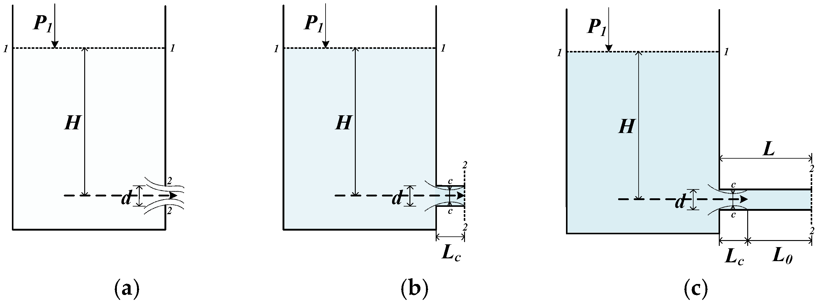
Figure 2. Diagram of three different types of discharge outlet: (a) orifice; (b) short stub fitting; and (c) drainage pipe.
Water 16 02894 g002
The discharge flow rates for the three types of outlets are calculated using Bernoulli’s equation, as shown below.
p 1 γ + v 1 2 2 g + z 1 = p 2 γ + v 2 2 2 g + z 2
The parameters are shown in Figure 2. Here p 1 and p 2 represent the pressures at points 1 and 2, including contributions from atmospheric pressure (N/m2), and γ is the specific weight of the fluid (N/m3). The terms p 1 γ and p 2 γ denote the pressure head. v 1 and v 2 are fluid velocity at point 1 and point 2 (m/s), and g is the acceleration due to gravity (approximately 9.81 m/s2 on Earth). The terms v 1 2 2 g and v 2 2 2 g represent the velocity head. z 1 and z 2 are the elevation head at points 1 and 2 (m). In Figure 2, the ‘c’ labels at both ends of the flow contraction indicate the distance between the two points where the fluid constricts. This distance can be used to calculate the contraction coefficient, which is typically employed to evaluate the efficiency of fluid flow and its impact on pressure loss.
  • Orifice
Referring to Equation (1), since p 1 and p 2 are exposed to atmospheric pressure, p 1 = p 2 , v 1 = 0, and the difference in water head, z 1 z 2 , equals H. The orifice resistance coefficient ξ o = 0.05 , and the orifice discharge contraction coefficient Cc = 0.61 [40], the discharge velocity v 2 o at the orifice and orifice discharge rate Q o   can be derived as Equations (2) and (3), respectively.
v 2 o = 1 1 + ξ o 2 g H
Q o = 0.60   A o 2 g H
where A o = orifice cross section area (m2) and g = gravitational acceleration (m/s2).
2.
Short Stub Fitting
The discharge velocity v 2 s p for the type of short stub fitting can be derived and shown in Equation (4). With resistance coefficient ξ p = 0.5 [40], the short stub fitting discharge rate Q s p is shown in Equation (5).
v 2 s p = 1 1 + ξ p 2 g H
Q s p = 0.82 A s p 2 g H
where A s p = short stub fitting cross section area (m2).
3.
Drainage Pipe
The discharge velocity v 2 p and discharge rate Q p for the drainage pipe outlet can be calculated and derived as Equations (6) and (7), respectively.
v 2 p = 1 1 + ξ p + f L d 2 g H
Q p = 1 1.5 + f L d A p 2 g H
where f = friction factor of pipe wall; L = pipe length (m); d = drainage pipe diameter (m); and A p = drainage pipe cross section area (m2).
In the equations, the friction factor f needs to be calculated iteratively considering both the Reynolds number (Re) and the drainage pipe discharge velocity v 2 p . When R e 2100 , it indicates laminar flow condition, and the friction factor f of the pipe can be expressed as Equation (8). When R e ≥ 4000, it indicates turbulent flow conditions, and the friction factor f is calculated using the Swamee–Jain Formula [41] as shown in Equation (9). When 2100 < R e < 4000 it indicates a transitional flow condition and f needs to be estimated using interpolation methods. The Reynolds number can be obtained by Equation (10).
f = 64 R e
f = 0.25 l o g ε d 3.7 + 5.74 R e 0.9 2
R e = ρ × v 2 p × d μ
where ε = the roughness coefficient of the pipe (10−3 m). Drainage pipes are commonly made of rigid polyvinyl chloride (PVC-U), for which ε = 0.0015, ρ = fluid density (kg/m3), and μ = is fluid dynamic viscosity ( P a · s ).

2.3. Location of the Discharge Outlet

The location of the discharge outlet impacts on both the retention and detention capacities of the RWHS tank. Most studies typically use between 25% and 75% of the tank volume for detention space [29,32,37]. This study will explore five different percentages of tank volume designated as detention space for stormwater management: 0%, 25%, 50%, 75%, and 100%. These configurations are referred to as CSFD-0 (i.e., conv. RWHS), CSFD-25, CSFD-50, CSFD-75, and CSFD-100, as shown in Figure 3. Since the 0% detention volume allocation (CSFD-0) aligns with the way tank volume is typically allocated in conv. RWHS, we refer to it as “PR-RWHS with CSFD-0” when discussing differences in detention volume allocation. For comparisons of pre- and post-retrofit effects, we use “conv. RWHS” to provide a clearer, more consistent interpretation in both practical and physical terms.

2.4. Model Description

Figure 4 illustrates the typical domestic RWHS in Taiwan. In this system, runoff from rooftops is directed to a ground-level storage tank, from which rainwater is pumped to rooftop tanks for storage. The stored rainwater is then distributed via gravity for toilet flushing or irrigation. If the rainwater supply is insufficient to meet demand, the municipal water system automatically supplements it. The PR-RWHS is similar to this existing system but includes an additional elevated passive outlet.
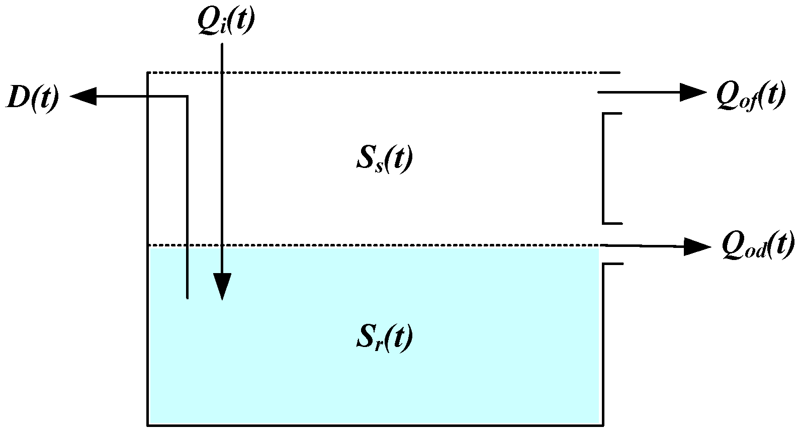
A model was developed to continuously simulate the behavior of different discharge outlet types, outlet sizes, and outlet locations. The volume stored in the PR-RWHS tank is influenced by factors such as the inflow rate, water demand, overflow, and discharge from the outlet, with evaporation losses ignored [42]. The water budget for the tank is illustrated in Figure 5 and can be represented by Equation (11).
Sr(t) = Sr(t − 1) + Qi(t) − D(t) − Qof(t) − Qod(t), 0 ≤ Sr(t), Sr(t) ≤ Smax
where Sr(t) = volume in store at time t (m3); and Sr(t1) = volume in store at time t − 1 (m3): Qi(t) = inflow volume at time t (m3); D(t) = water demand at time t (m3), with the maximum rainwater usage set at 100 L/day per person [2]; Qof(t) = overflow volume at time t (m3); Qod(t) = passive release volume at time t (m3); and Smax = the tank’s maximum storage volume (m3).
The inflow rate Qi(t) can be calculated by the Rational Formula [43]:
Qi(t) = c × i(t) × Ac
where c = runoff coefficient, taken as 0.82 for concrete flat roofs, and i(t) = rainfall depth at time t (m).
The regulated stormwater release Qo(t) of a PR-RWHS included the passive release from the outlet and overflow:
Qo(t) = Qof(t) + Qod(t)
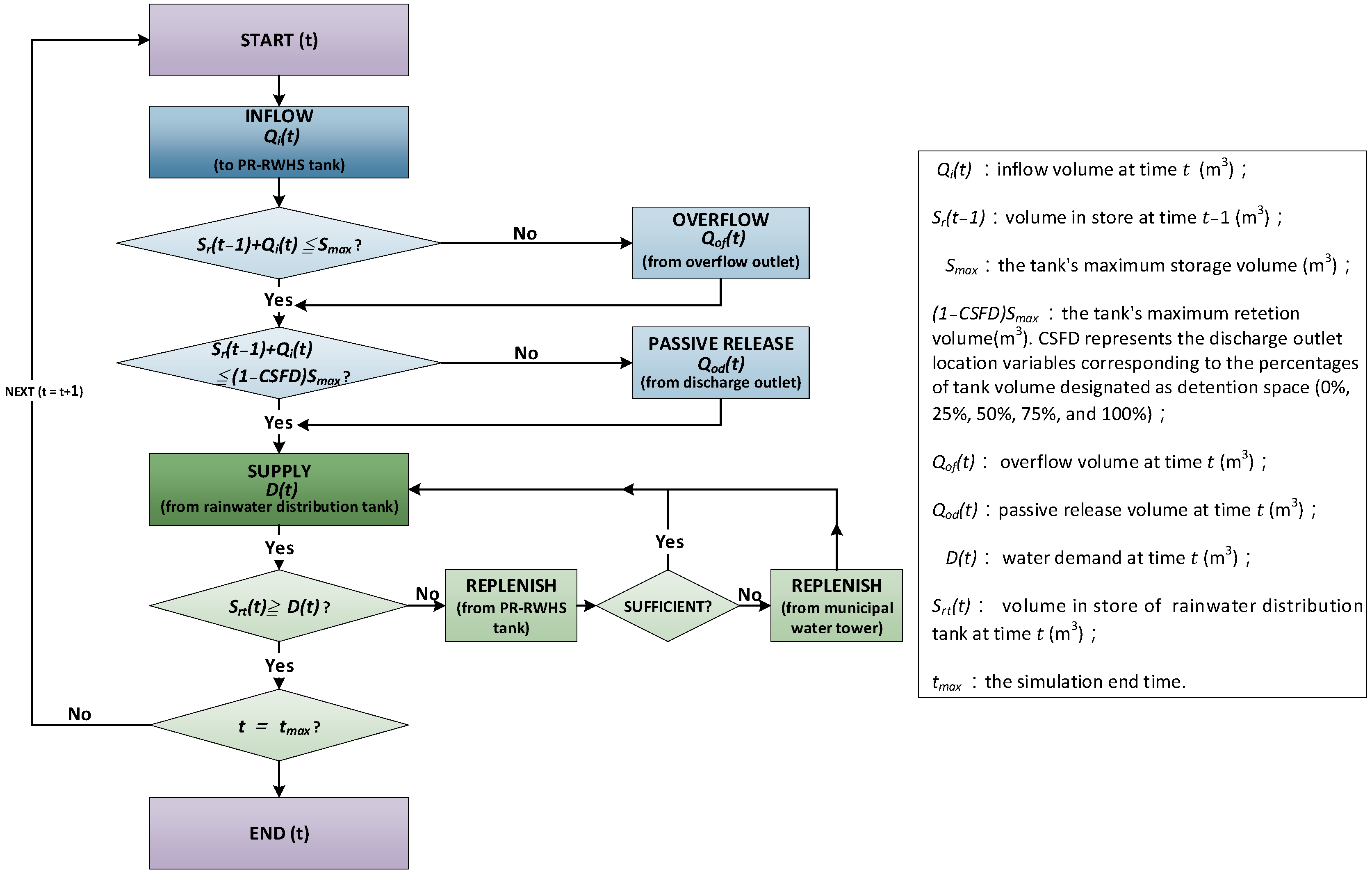
A Yield-After-Spillage (YAS) approach was employed for its conservative method of simulating RWHS behavior [44]. Consequently, the PR-RWHS Simulation Model was developed based on the operational process described earlier, as illustrated in Figure 6. The model was created using Microsoft Office Excel with Visual Basic for Applications (VBA) programming to facilitate various decision analyses.
The performance of the PR-RWHS was evaluated using indicators that characterize both water supply and stormwater management. Each objective is assessed through two parameters, focusing on volumetric efficiency and frequency characteristics. While many studies emphasize long-term retention, this study highlights event-based retention and peak runoff statistics, which are crucial for flood mitigation. Therefore, all three assessment indicators are expressed as proportions of total volume or total time steps to ensure comparability across different configurations and scenarios.
  • Peak Flow Mitigation Rate ( M Q p )
M Q p was an indicator used to assess the effectiveness of PR-RWHS in reducing peak flow compared to the peak flow from the inflow of a tank during a rainfall event. A higher M Q p value reflects a greater capacity of the PR-RWHS to mitigate peak flow, and this serves as a key factor in the discharge outlet design.
M Q p = Q p i Q p , P R R W H S Q p i × 100 %
where Q p i = peak inflow during a rainfall event and Q p , P R R W H S = peak flow of regulated stormwater release (Qof + Qod) during a rainfall event.
2.
Peak Flow Lag Time ( T l a g )
T l a g referred to the delay in the occurrence of peak flow compared to the peak inflow during a rainfall event. A larger value of T l a g indicates that the PR-RWHS is more effective in mitigating intense rainfall and serves as a reference for the design of discharge outlets.
T l a g = t Q p , P R R W H S t Q p i
where t Q p i = time of peak inflow during a rainfall event and t Q p ,   P R R W H S = time of peak regulated stormwater release during a rainfall event.
3.
Water Supply Reliability ( R v )
The RWHS performance was generally described in terms of reliability [21]. Volumetric reliability ( R v ) was defined as total actual water supply over water demand and was available under all circumstances [45]. It could be mathematically expressed as
R v = a c t u a l   r a i n w a t e r   s u p p l y w a t e r   d e m a n d = Σ Y t Σ D t × 100 %

2.5. Representative Buildings for Analysis

2.5.1. Classification of Building Types

National statistical data categorized residential buildings by the number of floors into four groups: one to three floors, four to five floors, six to ten floors, and higher floors [46]. The proportions for these categories were 44.06%, 22.02%, 11.23%, and 22.69%, respectively [47]. More than two-thirds of residents lived in apartments, most of which had between two and five stories, built by both public and private sectors. For high-rise buildings, raft foundations were commonly used for RWHS storage tanks, equipped with pumping systems. This study primarily focuses on the first three categories, using ground-level storage tanks. For comparisons, the study selected a detached house (DH) as a representative for Category I; a four-story building (FSB) with two households per floor for Category II; and an eight-story building (ESB) with four households per floor for Category III.

2.5.2. RWHS Tank Volume Design

According to the Green Building Evaluation Manual—Basic Type (GBEM-BC), the volume required for an RWHS tank is estimated as follows [2]:
V s R 1000 × A c × N s
where V s = the tank volume (m3), and its maximum storage volume is Smax; A c = the effective roof area (m2); R = the average daily precipitation for the selected region (mm/day); and N s = the number of storage days (days) for the selected region.
Taiwan is divided into five regions—North, Central, South, East, and Offshore—based on variations in rainfall amounts. Each region has distinct values for R (rainfall) and N s (storm frequency). This study focuses on Taipei in the northern region, where R and N s are 6.31 and 8.12, respectively [2].
In Taiwan, the number of people per household ranges from 2.8 to 3.4, with an average of 3.0 people [47]. The floor area of a housing unit varies depending on structural material and location, ranging from 111.4 to 137.6 m2, with an average of 125 m2 per unit [2]. The daily potable water demand per person is 0.25 m3. In the residential sector, up to 40% of this demand can be replaced by rainwater, mainly for toilet flushing and irrigation, corresponding to a maximum rainwater usage of 100 L/day per person [2]. Based on this information, tank volumes for different representative buildings were calculated, as shown in Table 1. To align with available market options, practical tank volumes were selected. The basic information for the selected representative buildings is summarized in Table 1.

2.6. Climate Data

Rainfall data for this investigation were provided by the Central Weather Agency’s Ministry of Transportation and Communications. The data series include precipitation records from the rainfall gauging station in Taipei, located in the northern part of the city at an elevation of approximately 5.3 m above sea level. The station measures rainfall with a time resolution of one hour and an accuracy of 0.2 mm. For the long-term simulation of water supply and stormwater management effectiveness, ten years of data (2014–2023) were used.
To determine the size of the passive discharge outlet, design storms used for stormwater drainage system design in the Taipei area were applied. Consistency in selecting design events is crucial to ensure risk levels are maintained throughout the watershed [39]. Additionally, historical rainfall data for potentially hazardous events were used to validate the results obtained from the design storms.

2.6.1. Design Storms

In the Taipei area, the design return periods for storm sewer systems are set as follows: 1–2 years for townships, 2–3 years for counties, and 5 years for cities [3]. Considering the impacts of climate change and the increasing frequency of extreme rainfall events, it is anticipated that the return period will gradually increase to 10 years over the next decade [48,49,50].
Therefore, for the simulation, design storms with return periods of 2, 5, and 10 years were used. Each storm had a rainfall duration of 120 min and a time resolution of 5 min intervals. The design storm profiles were based on the Horner rainfall intensity formula [50]:
I t = a ( t d + b ) c
where I t is the rainfall depth at time t d (mm/5 min) and t d is the rainfall duration (min). The parameters a, b, and c for different return periods are as follows:
  • 2-year return period: a = 2339.700, b = 25.905, c = 0.798;
  • 5-year return period: a = 2250.161, b = 28.309, c = 0.731;
  • 10-year return period: a = 1942.806, b = 28.556, c = 0.674.
The sizes of the passive discharge outlets for the selected types and representative buildings were evaluated using various outlet diameters (5 mm, 10 mm, 15 mm, 20 mm, 25 mm, 30 mm, 35 mm, 40 mm, 45 mm, and 50 mm) and different location configurations. Using the PR-RWHS model established in Section 2.4, parameters for three representative buildings were simulated, as shown in Table 2. This process involves comparing the peak inflow rates during rainfall events with the regulated peak flow release to analyze the peak flow mitigation rates and peak flow lag times, with the optimal outlet diameter selected based on the best results.

2.6.2. Probably Hazardous Rainfall Events

In 2020, the Central Weather Agency conducted a comprehensive review of historical rainfall and flooding caused by heavy rain. Based on recent short-duration intense rainfall events, four categories of rainfall intensity were recommended: Heavy Rain (HR), Torrential Rain (TR), Severe Torrential Rain (STR), and Extreme Torrential Rain (ETR) [51]. These categories can be further classified into short-duration and long-duration events, as summarized in Table 3. These classifications are now used as design standards in the Runoff Allocation and Outflow Control projects.
To assess the suitability of the discharge outlet sizes determined by design storms, potentially hazardous rainfall events from historical data will be used for verification. A summary of the parameters associated with these potentially hazardous rainfall events for the three representative buildings is provided in Table 4.

2.7. Determination of Location of Discharge Outlet

Once the type and size of the discharge outlet have been determined, the next step is to establish the outlet’s location, which affects the volumes of retention and detention. Continuous rainfall data from 2014 to 2023 [52] were used in the simulation model to evaluate the long-term effectiveness of water supply and stormwater management.
In Taiwan, rainfall is unevenly distributed and predominantly occurs during the wet season from May to October. The wet season accounts for approximately 65% of rainfall in the north and up to 90% in the south [1]. The average monthly rainfall distribution for the Taipei rain gauge station is shown in Figure 7 [53]. Considering the uneven distribution of rainfall, three operational scenarios are recommended and described below.
  • Scenario 1: The conv. RWHS operated year-round.
  • Scenario 2: The discharge outlet of the PR-RWHS was open year-round.
  • Scenario 3: The discharge outlet of the PR-RWHS was open during the wet season and closed during the dry season, provided the discharge outlet was equipped with valves.
Figure 7. Average monthly rainfall distribution in Taipei rain gauge station.
Water 16 02894 g007
A summary of the simulated parameters for the three representative buildings is provided in Table 5.
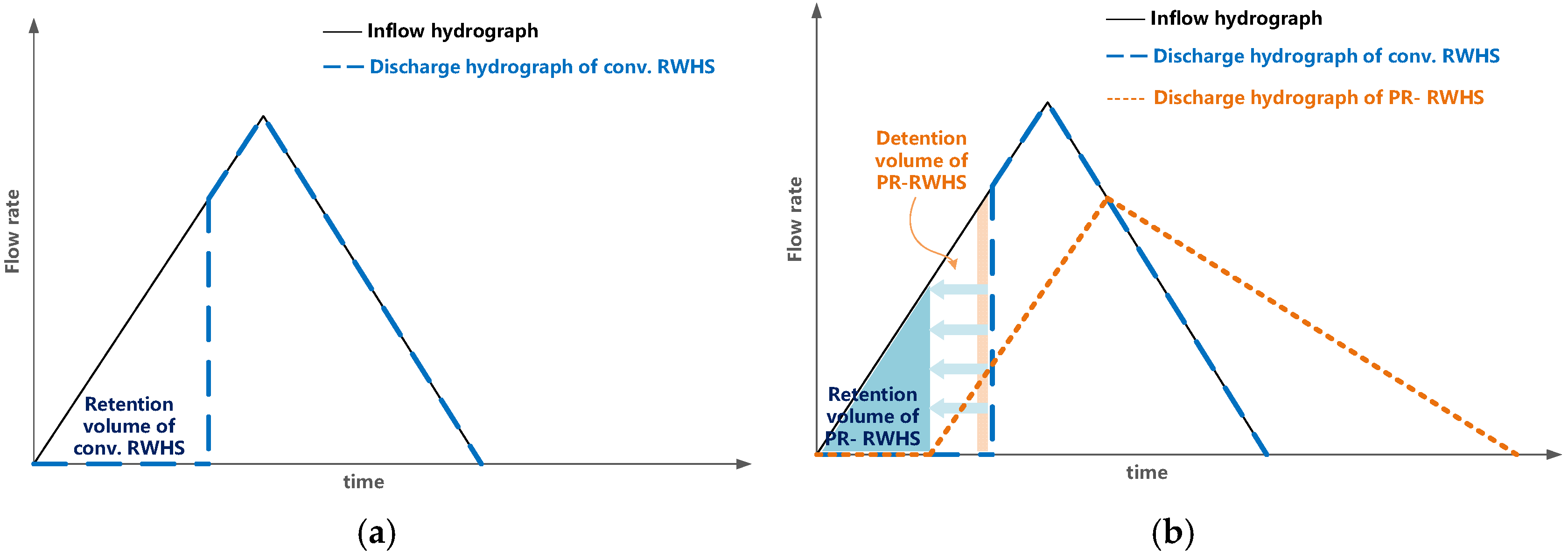
To evaluate the dual purposes of PR-RWHSs, both water supply and release volume are commonly assessed. For a given rainfall event, a conv. RWHS retains a portion of the rainwater, as illustrated by its discharge hydrograph and inflow hydrograph in Figure 8a. This figure shows that the conv. RWHS can reduce the inflow volume to some extent. In contrast, with the PR-RWHS design, a portion of the retention volume is converted into detention volume for stormwater management. The discharge hydrograph for the PR-RWHS, shown in Figure 8b, demonstrates that rainwater is gradually released and regulated by the discharge outlet, leading to an earlier onset on the hydrograph. The release volume of the PR-RWHS is greater than that of the conv. RWHS, but it features a lower peak flow and a longer base time. With a larger detention volume, the discharge hydrograph for the PR-RWHS shifts to the left, resulting in a higher release volume, lower peak flow, and an extended base time. Thus, in the long-term simulation using continuous rainfall events, the regulated stormwater release of PR-RWHS will be assessed to evaluate its stormwater management benefits. This assessment will help to determine the optimal location for the discharge outlet under the three different scenarios.
The location of discharge outlets in PR-RWHSs influences the proportion of detention volume in the storage tank. Increasing the detention volume enhances stormwater release but reduces the volume available for the water supply. Since conv. RWHSs primarily serve water supply needs, retrofitting for dual purposes must still ensure an adequate water supply. To identify the optimal discharge outlet location for various buildings and scenarios, consider the following three steps:
Step 1: Perform a water supply reliability analysis using continuous rainfall data for various buildings, scenarios, and discharge outlet locations. Evaluate how different scenarios and outlet locations impact water supply reliability. Determine the maximum acceptable decrease in reliability to define feasible outlet locations.
Step 2. Develop average annual water supply and regulated stormwater release curves. Identify the break-even point where these curves intersect and establish the feasible range of discharge outlet locations.
Step 3. Conduct an incremental analysis to assess the benefits of water supply and regulated stormwater release. Focus on selecting outlet locations that offer the largest increases in stormwater release with the smallest decreases in water supply. Compare these feasible solutions with those identified in Steps 1 and 2 to determine the optimal discharge outlet location.

3. Results and Discussion

3.1. Selection of Discharge Outlet Type

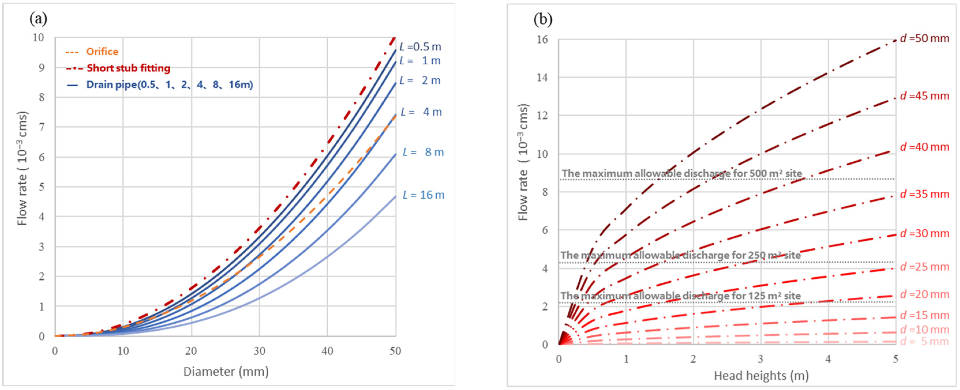
Three types of discharge outlets—an orifice, a short stub fitting, and a drainage pipe—were selected for analysis. For comparison, a water head of 2 m and discharge outlet diameters ranging from 5 mm to 50 mm were considered. For the drainage pipe outlet, pipe lengths of 0.5 m, 1 m, 2 m, 4 m, 8 m, and 16 m were evaluated. The discharge rates for various diameters and pipe lengths are calculated and plotted using the flow equations established in Section 2.2, as shown in Figure 9a. Across all outlet diameters, the short stub fitting outlet demonstrated superior discharge rates, followed by the drainage pipe outlet with pipe lengths shorter than 4 m. However, the discharge rate of the drainage pipe decreased as the pipe length increased. The discharge rate of the orifice was lower than the short stub fitting but higher than the drainage pipe for lengths longer than 4 m. Similar trends were observed for other water head conditions. Overall, the short stub fitting outlet exhibited superior discharge performance, requiring only three parameters (diameter, water head, and resistance coefficient) to calculate the discharge rate. Additionally, it offered advantages in terms of discharge performance, installation cost, operability, and maintenance. Based on this analysis, the short stub fitting outlet was selected for further study. Therefore, the discharge rates for various water heads and outlet diameters for the short stub fitting outlet are shown in Figure 9b, providing valuable information for the subsequent simulation analysis.

3.2. Determination of Discharge Outlet Size Using Design Storm

To comply with discharge regulations set by the Taipei and New Taipei City governments, the maximum allowable discharge rate from detention facilities is limited to 0.0000173 m3 per second per m2. Therefore, the required outlet diameters of the short stub fitting, based on different water heads for construction areas of 125 m2, 250 m2, and 500 m2, ranged from 15 to 50 mm, 25 to 50 mm, and 35 to 50 mm, respectively. These values are also presented in Figure 9b.
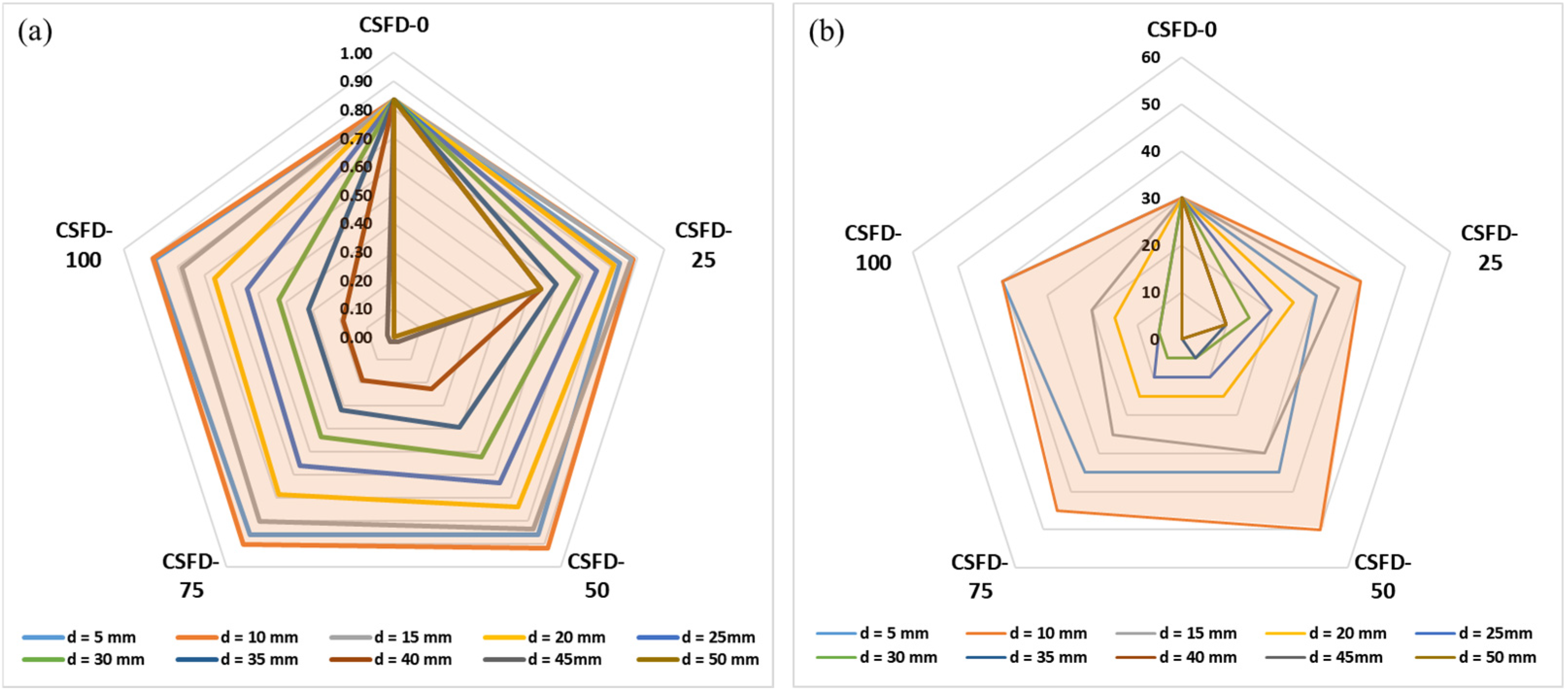
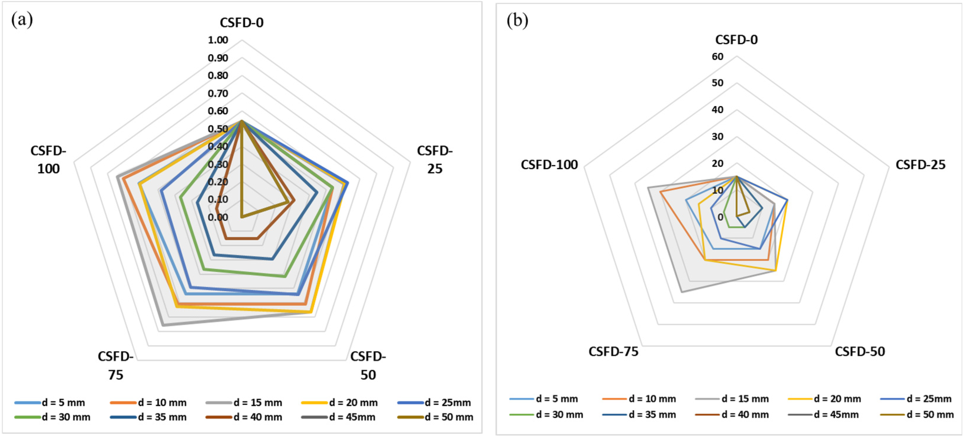
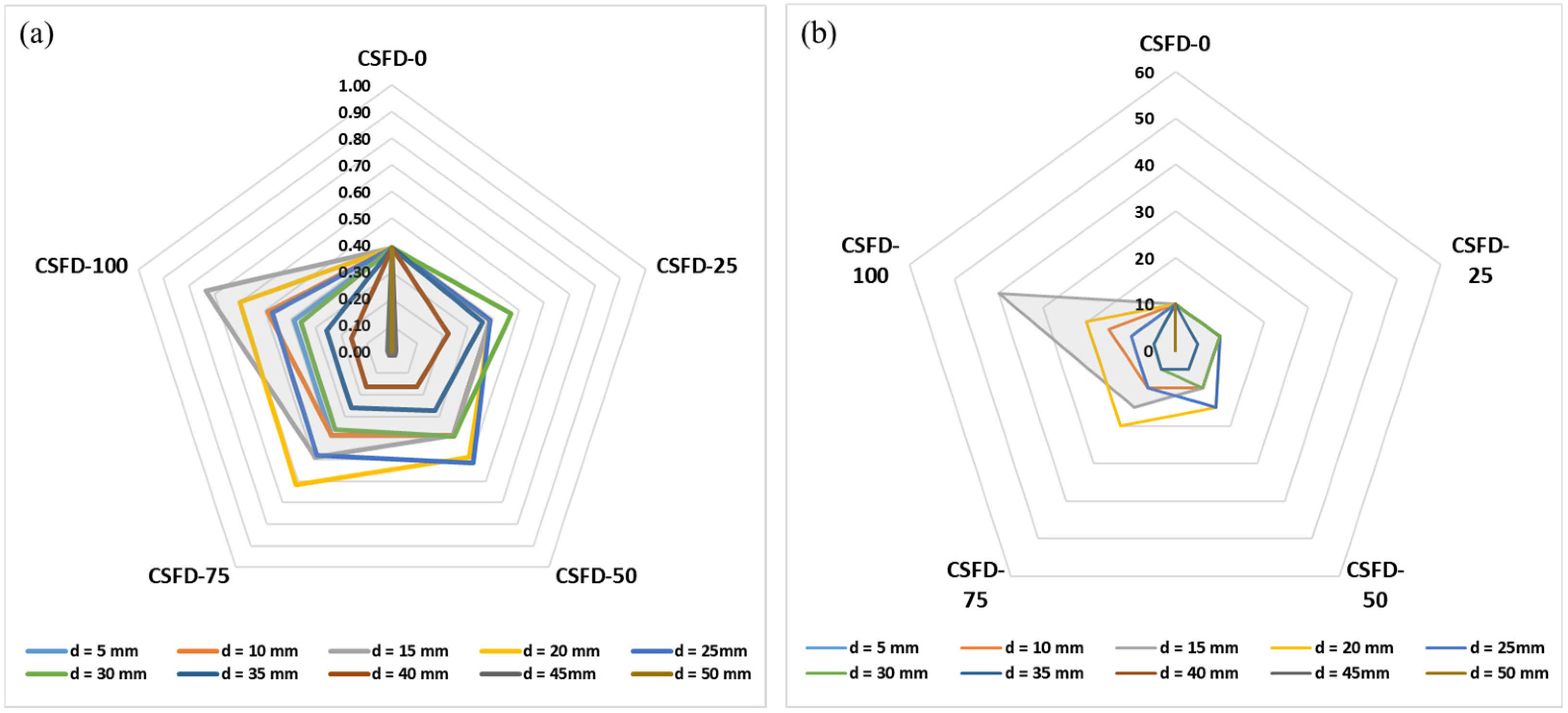
To provide a more detailed analysis, ten different outlet diameters (5 mm, 10 mm, 15 mm, 20 mm, 25 mm, 30 mm, 35 mm, 40 mm, 45 mm, and 50 mm) were evaluated, along with five outlet locations (CSFD-0, CSFD-25, CSFD-50, CSFD-75, CSFD-100). The peak flow mitigation rate and peak flow lag times for these diameters and locations were analyzed using 2-year, 5-year, and 10-year return period design storms, with results displayed in radar plots.
For a detailed illustration of the relationships between these variables, the results for the DH representative building under different return periods are shown in Figure 10, Figure 11 and Figure 12.
Figure 10 shows that, for each outlet location, a range of outlet diameters yields higher peak flow mitigation rates and longer peak flow lag times, facilitating the selection of optimal diameters. As the diameter increases, the impact of the outlet location becomes more pronounced, influencing both indicators. The figure also shows that the most effective combination of the two indicators is with an outlet diameter of 10 mm and a location at CSFD-50. The changes in Figure 11 and Figure 12 are similar to those in Figure 10, but they highlight the differences among all combinations more clearly. For the 5-year return period design storm, Figure 11 indicates that the most effective combination is an outlet diameter of 15 mm and a location at CSFD-75. For the 10-year return period design storm, Figure 12 shows the most effective case is an outlet diameter of 15 mm at CSFD-100.
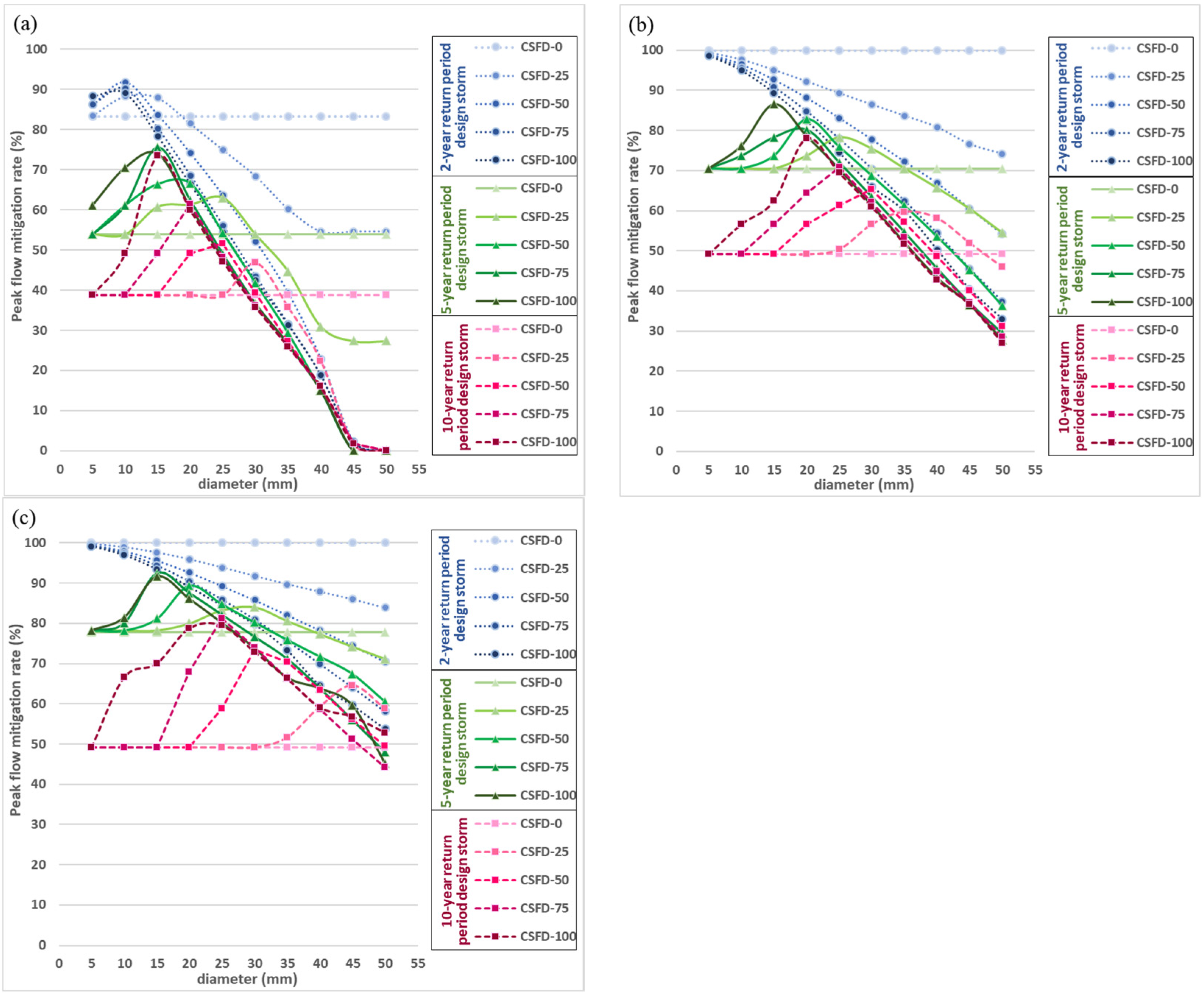
Based on these results, the trends in the most effective combinations of outlet diameters and locations in the radar plots of peak flow lag time and peak flow mitigation rate remain consistent across different design storm return periods. The radar plots for the other two buildings (the FSB and ESB) show similar trends. Therefore, in discussing the stormwater management performance of the PR-RWHS in relation to the numerous variable parameters, the focus will be on one evaluation indicator—peak flow mitigation rate—for further analysis of the representative buildings. For practical engineering applications, a fixed discharge outlet size is preferred across different return periods for each building type. The data from the radar plots for the three representative buildings have been rearranged and plotted in Figure 13a–c for comparison.
From Figure 13a, for the 2-year return period design storm, the highest peak flow mitigation rate was 91.84%, occurring with a 10 mm discharge outlet at the CSFD-50 location. For the 5-year return period, the highest peak flow mitigation rate was 75.64% with a 15 mm outlet at CSFD-75, while for the 10-year return period, the highest was 73.45% with a 15 mm outlet at CSFD-100. If a 15 mm diameter outlet were used for the 2-year return period storm, the reduction in peak flow mitigation across all locations would remain acceptable, with a peak rate of 87.93% at CSFD-25.
Figure 13b,c show that for the 2-year return period design storm, there was no outflow at CSFD-0 because the larger tank volumes of the two buildings could retain most of the rainfall. Peak flow mitigation rates at the other locations were lower than at CSFD-0. In Figure 13b, the highest mitigation rate for the 5-year return period was 86.55% with a 15 mm outlet at CSFD-100. For the 10-year return period, the highest rate was 77.99% with a 20 mm outlet at CSFD-100. If a 15 mm outlet was used, the mitigation rate would reduce to 62.40%, which remains within an acceptable range. In Figure 13c, the highest peak flow mitigation rate for the 5-year return period was 92.38% with a 15 mm outlet at CSFD-75. For the 10-year return period, the highest rate was 81.13% with a 25 mm outlet at CSFD-75. Using a 15 mm outlet reduced the rate to 70.04% at CSFD-100, still within acceptable limits.
Ignoring the outlet location, the feasible discharge outlet diameters for the highest peak flow mitigation rates across the three representative buildings and different return period storms are summarized in Table 6. For the 5-year return period, all buildings had the same recommended discharge diameter, while for the 10-year return period, diameters varied between 15 mm and 25 mm depending on the building. Considering the current design standards in Taipei (discussed in Section 2.6.1), this study recommends a 15 mm outlet diameter for PR-RWHS designs across different representative buildings based on the 5-year return period design storm.
To further assess the suitability of selecting a 15 mm discharge outlet diameter, the maximum peak flow mitigation rates for three return period design storms, three representative buildings, and various discharge outlet locations were calculated and compared. These results are presented in Table 7. The differences in maximum peak flow mitigation rates between the PR-RWHS and conv. RWHS designs are displayed in the “Difference” column. In most cases, the PR-RWHS designs exhibited higher peak flow mitigation rates than the conv. RWHS configurations. For the FSB and ESB, which have larger tank volumes capable of capturing most rainfall under the CSFD-0 design, the maximum peak flow mitigation rates reached 100% for the 2-year return period storm event. As a result, the differences in peak flow mitigation rates between the PR-RWHS and conv. RWHS designs were negative in these cases. Overall, the results indicate that selecting a 15 mm discharge outlet diameter yields higher peak flow mitigation rates than the conv. RWHS design and is considered acceptable.

3.3. Validation of Discharge Outlet Diameter Using Probably Hazardous Rainfall Events

To validate the discharge outlet diameter determined in the previous section based on the design storms, historical rainfall data was used to test this value. From the 2014–2023 historical rainfall data, 47 potentially hazardous rainfall events were identified: 10 S-HR events, 27 L-HR events, 6 S-TR events, 3 L-TR events, and 1 L-STR event. Detailed information on these events, including rainfall timing, duration, and accumulated rainfall (AR), is provided in Table 8. Since only one L-STR event occurred, it has been excluded from the statistical analysis.
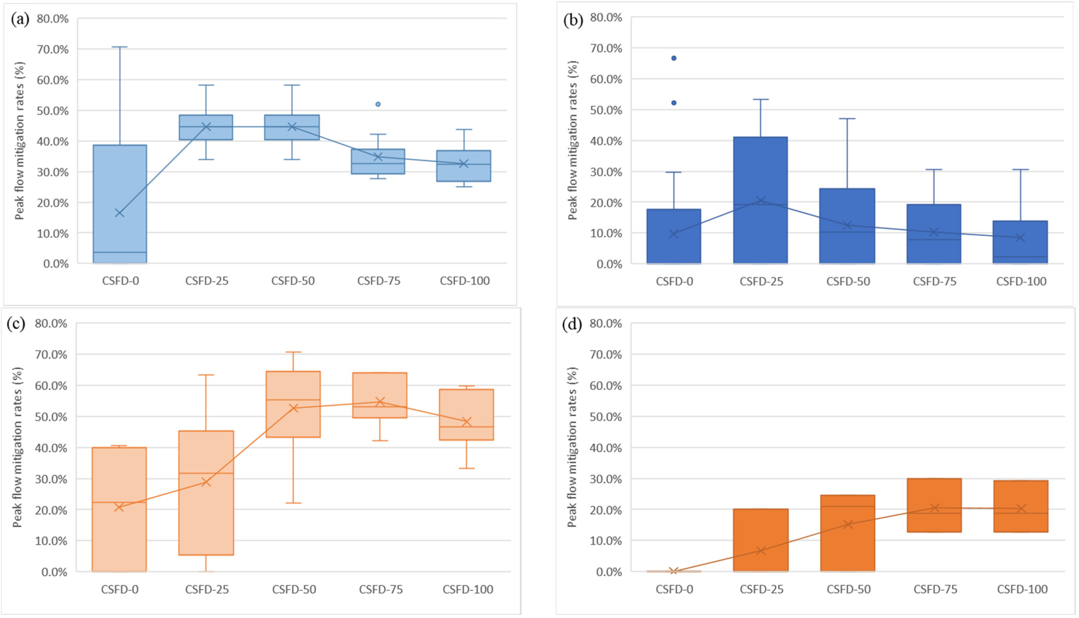
Continuous rainfall data from 2014 to 2023, with one hour time intervals and 15 mm discharge outlet diameters, were used in the simulation model. The peak flow mitigation rates were analyzed for four potentially hazardous rainfall events, considering different discharge outlet locations. Figure 14 presents the distribution of peak flow mitigation rates using a box-and-whisker plot (boxplot) for the DH across various locations, categorized by event types: S-HR, L-HR, S-TR, and L-TR. The boxplot displays the minimum value, lower quartile, median, upper quartile, maximum value, and any outliers.
The results indicated that the median peak flow mitigation rates for the PR-RWHS were consistently higher than those at the CSFD-0. The impact was particularly pronounced for short-duration events (S-HR and S-TR). Figure 14a,c demonstrated that the CSFD-50 location had the highest median value compared to the other locations. For long-duration events (L-HR and L-TR), while the median peak flow mitigation rates for the PR-RWHS remained higher than those for the conv. RWHS, the differences were less significant. In Figure 14b, the median value at the CSFD-0 location was zero because the storage tank was full before the flood peak arrived, resulting in zero peak flow mitigation for most rainfall events. Figure 14b also showed that the CSFD-25 location had the highest median value compared to other locations. Similarly, in Figure 14d, all rainfall events showed no peak flow mitigation capability at CSFD-0 for the same reason.
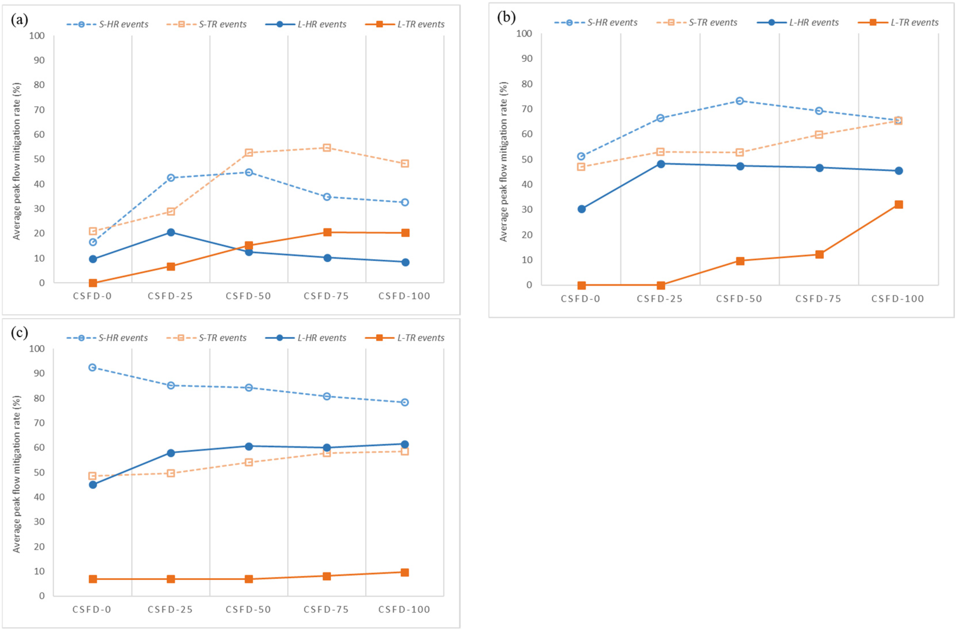
To enhance clarity, we replotted the results (Figure 15). This figure presents the average peak flow mitigation rates for different locations, rainfall events, and representative buildings (DH, FSB, and ESB).
Figure 15 illustrates the relationships between the average peak flow mitigation rate, discharge outlet locations, and various probably hazardous rainfall events for the three representative buildings. It was observed that, overall, the average peak flow mitigation rates for short-duration rainfall events (S-HR and S-TR), shown with dashed lines, were higher than those for long-duration events (L-HR and L-TR), depicted with solid lines. In most cases, the PR-RWHS designs had higher average peak flow mitigation rates than the conv. RWHSs, with the exception of the ESB for S-HR rainfall events. The reason for this exception lies in the ESB’s relatively large storage tank, which meant that most S-HR rainfall events in the conv. RWHS were intercepted, resulting in no outflow for most events and yielding an average peak flow mitigation rate of over 90%. In contrast, for other discharge outlet locations in the PR-RWHS design, flows still discharged through the outlets, which led to lower average peak flow mitigation rates compared to the conv. RWHS for S-HR events, as shown in Figure 15c.
For further comparison, the numerical data and ranges of change in the average peak flow mitigation rates for different outlet locations, probably hazardous rainfall events, and representative buildings are summarized in Table 9.
In the table, the range of average peak flow mitigation rates for PR-RWHS designs was generally higher than that for the conv. RWHS cases. For the ESBs, with their larger tank volumes, most of the rainfall was captured with the conv. RWHS, resulting in an average peak flow mitigation rate of 92.4% for S-HR rainfall events. Consequently, the differences in average peak flow mitigation rates between the PR-RWHS and conv. RWHS designs were negative.
Both Table 7 (from Section 3.2) and Table 9 aim to assess the simulation results of peak flow mitigation rates under varying levels of potentially hazardous rainfall events and different return periods of design storms. Both tables show significant improvements in peak flow mitigation rates for the PR-RWHS designs (with various discharge outlet locations) compared to the conv. RWHS. Moreover, even with more severe potentially hazardous rainfall events, the PR-RWHS consistently demonstrated superior performance across all representative buildings compared to the design storm cases.
Based on the above analysis and results, a 15 mm discharge outlet diameter provides higher peak flow mitigation rates than the conv. RWHS and is deemed reasonable and effective for enhancing stormwater management.

3.4. Determination of the Location of Discharge Outlets Using Continuous Rainfall Data

In the previous section, the PR-RWHS with a 15 mm discharge outlet and various outlet locations effectively reduced peak flow. However, different discharge outlet locations resulted in varying increases in detention volume, leading to different levels of decreased water supply capacity. Since the primary purpose of existing RWHSs is water supply, any retrofitting for dual purposes must prioritize maintaining an acceptable level of water supply.
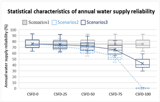
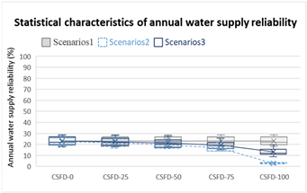
To evaluate this, ten years of continuous rainfall data were used in a simulation model to calculate the change in average annual water supply reliability across different discharge outlet locations and scenarios for three representative buildings (refer to the Section 2.7). Boxplots depicting the annual variation in water supply reliability and the average annual reliability for each scenario and location are shown in Table 10, Table 11 and Table 12. From the perspective of declining average annual water supply reliability, Scenario 3 performed better than Scenario 2 across all discharge outlet locations. For instance, at the CSFD-100 location in Scenario 2, the average annual water supply reliability fell below 5% for the ESB and approached zero for the FSB, indicating nearly nonexistent water supply capability, which is unacceptable. In contrast, Scenario 3 maintained acceptable levels of average annual water supply reliability, even at CSFD-100.
Considering Green Building requirements, which stipulate that rainwater should constitute 5% of total water use and noting that the maximum average annual water supply reliability for the ESB is 25.4%, it is recommended that the maximum allowable decrease (MAD) in average annual water supply reliability should not exceed 20% (MAD-20). Additionally, 10% (MAD-10) and 15% (MAD-15) decreases were also analyzed. For the DH (Table 10), the corresponding outlet locations are CSFD-50 for Scenario 2 and CSFD-75 for Scenario 3, which meet the requirements for MAD-10, MAD-15, and MAD-20. For the FSB (Table 11), CSFD-50 for Scenario 2 meets MAD-10 and MAD-15, and CSFD-75 meets MAD-20; CSFD-50 for Scenario 3 meets MAD-10, and CSFD-75 meets both MAD-15 and MAD-20. For the ESB (Table 12), CSFD-75 for Scenario 2 meets MAD-10, MAD-15, and MAD-20; CSFD-75 for Scenario 3 meets MAD-10, and CSFD-100 meets both MAD-15 and MAD-20.
In the previous analysis, appropriate discharge outlet locations were determined based on acceptable decreases in average annual water supply reliability across different representative buildings and scenarios. To verify these appropriate discharge outlet locations, their performance in terms of discharge volume change needs to be assessed. The stormwater release performance for different scenarios, representative buildings, and discharge outlet locations will be explored and compared using ten years of continuous rainfall data in the simulation model. The results will be discussed in detail for each representative building.
  • Representative DH Building
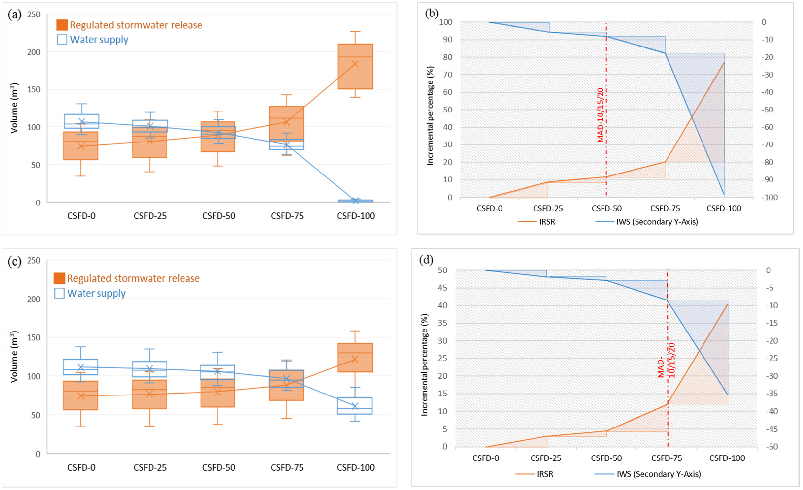
Figure 16a,c display the annual variation in water supply and regulated stormwater release at different discharge outlet locations for scenarios 2 and 3. The curves in these figures represent the linked average values. The figures show that as detention volume increased, the average annual regulated stormwater release also increased, while the average annual water supply decreased. Additionally, scenario 2 resulted in a higher percentage reduction in average annual water supply compared to scenario 3 but achieved a greater increase in average annual regulated stormwater release. Figure 16c,d provide an incremental analysis of average annual water supply and regulated stormwater release across different discharge outlet locations for scenarios 2 and 3.
In Figure 16a, the break-even point of the two curves is around CSFD-50, which aligns with the results obtained from the MAD-10, -15, and -20 analyses. Figure 16b shows that the incremental values of the regulated stormwater release (IRSR) exceeded those of the water supply (IWS) between CSFD-0 and CSFD-50, indicating that increased tank space for detention is more effective for IRSR than for IWS. Conversely, the absolute values of the IRSR were less than those of the IWS between CSFD-50 and CSFD-100, suggesting that increased tank space becomes less effective for IRSR compared to IWS. This analysis suggests that CSFD-50 balances water supply and stormwater management effectively. Therefore, for scenario 2 in the DH, the discharge outlet should be positioned at CSFD-50.
In Figure 16c, the break-even point of the two curves is around CSFD-75, consistent with the results from the MAD-10, -15, and -20 analyses. Figure 16d demonstrates that the IRSR values exceeded the IWS values for all discharge outlet locations (CSFD-0 to CSFD-100), indicating that increased detention volume enhances the IRSR more than the IWS. However, beyond CSFD-75, the incremental values of the IRSR and IWS became almost similar, suggesting that increasing the detention volume further offers diminishing returns. Therefore, for scenario 3 in the DH, CSFD-75 is recommended.
2.
Representative FSB
Figure 17a–d present the same plots as Figure 16a–d but use the FSB dataset.
In Figure 17a, the break-even point of the two curves is located around CSFD-75. This aligns with the previous analysis, which selected CSFD-50 based on the MAD-10/15 analyses and CSFD-75 for the MAD-20 analysis. Figure 17b shows that between CSFD-50 and CSFD-75, the absolute values of the Incremental Regulated Stormwater Release (IRSR) exceeded those of the Incremental Water Supply (IWS), indicating that moving from CSFD-50 to CSFD-75 improves IRSR more than IWS. However, beyond CSFD-75, the water supply drops significantly, making further increases in detention volume less effective. Therefore, for scenario 2 in the FSB, CSFD-75 is recommended.
In Figure 17c, the break-even point falls between CSFD-75 and CSFD-100. Previous analysis had selected CSFD-50 for MAD-10 and CSFD-75 for MAD-15/20. Figure 17d reveals that the IRSR exceeded the IWS across all discharge outlet locations (CSFD-0 to CSFD-100). This suggests that increasing detention volume is more effective for IRSR than for IWS. However, given the limitations on water supply reliability, further increases in detention volume are less justified. Thus, for scenario 3 in the FSB, CSFD-75 is recommended.
3.
Representative ESB
Figure 18a–d present the same plots as Figure 16a–d but use the ESB dataset.
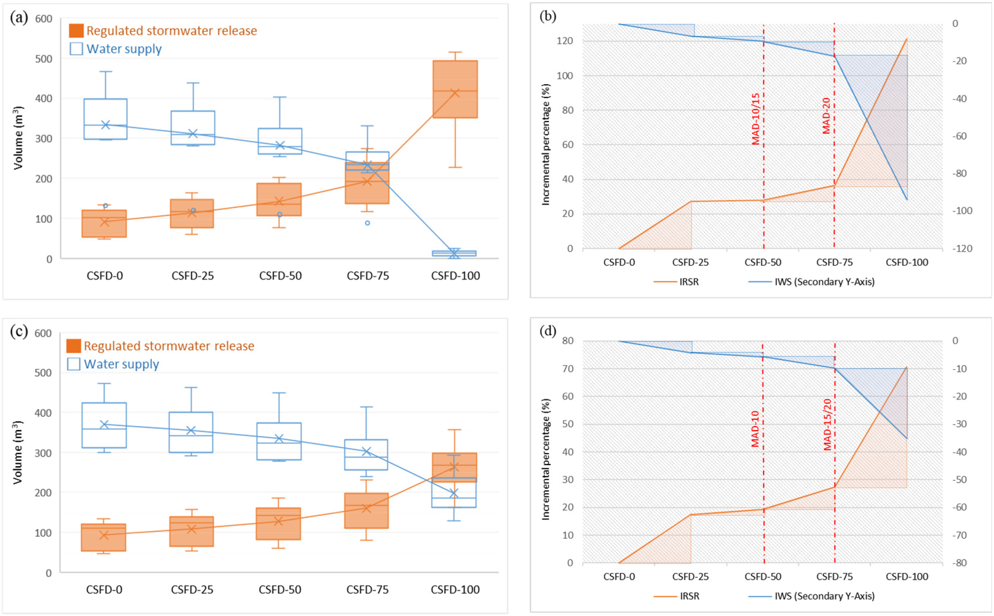
In Figure 18a, the break-even point of the two curves is near CSFD-75, closely aligning with results from the MAD-10, -15, and -20 analyses. Figure 18b shows that the incremental regulated stormwater release (IRSR) consistently exceeded the incremental water supply (IWS) across all discharge outlet locations (CSFD-0 to CSFD-100). This indicates that increased detention volume is more effective for IRSR than for IWS. From a stormwater management perspective, CSFD-100 would be the optimal choice. However, since the water supply fell significantly from CSFD-75 to CSFD-100, increasing the detention volume beyond CSFD-75 does not make much sense. Thus, for scenario 2 in the ESB, CSFD-75 is recommended.
In Figure 18c, the break-even point of the two curves is at CSFD-100, which also aligns with the results from the MAD-10, -15, and -20 analyses. Figure 18d shows that the IRSR exceeded the IWS for all of the discharge outlet locations (CSFD-0 to CSFD-100). This suggests that larger detention volumes are more effective for IRSR than for IWS. From a stormwater management perspective, CSFD-100 is the best choice. Therefore, for scenario 3 in the ESB, CSFD-100 is recommended.

4. Conclusions and Recommendations

Taiwan is currently facing, and will continue to face, significant challenges related to water shortages and extreme rainfall events due to climate change and urban development. Rainwater harvesting systems (RWHSs) have been recognized not only as a new alternative water resource but also as an effective urban stormwater management strategy. Retrofitting existing RWHSs for dual purposes requires a simple and cost-effective passive release system, particularly suited to Taiwan’s context. Therefore, assessing methodologies for designing passive RWHSs at the household level is crucial. This study presents a systematic framework for designing passively operated RWHSs.
When designing passively operated RWHSs with the dual functions of water supply and stormwater management, four key aspects must be considered: the type of discharge outlet, the size of the discharge outlet, the location of the passive discharge outlet, and the long-term operation strategy.
Three types of passive discharge outlets—orifices, short stub fittings, and drainage pipes—were evaluated and compared. The discharge flow formulas for these outlet types were developed, and their performance curves for selected diameters and drainage pipe lengths at constant water heads were plotted. Results indicate that short stub fittings outperform the other types in discharge flow performance across all selected diameters.
The discharge outlet must be sized to accommodate the design storm to ensure consistency throughout the watershed. This study evaluated the appropriate discharge outlet diameter by comparing the peak flow mitigation across the selected diameters and three different representative buildings using design storms with 2-, 5-, and 10-year return periods in the Taipei area. For a 5-year return period design storm, all representative buildings used a discharge outlet diameter of 15 mm. However, for a 10-year return period design storm, the diameter varied from 15 to 25 mm among different buildings. To align with the current design standards in Taipei, the 5-year return period design storm was selected, and a 15 mm diameter for the discharge outlets in the PR-RWHS design was recommended. The results showed that a 15 mm discharge outlet diameter provided higher peak flow mitigation rates compared to conv. RWHSs. Additionally, verification using 47 potentially hazardous rainfall events—both short- and long-duration events from 2014 to 2023—confirmed that the 15 mm diameter effectively mitigated peak flows, especially for short-duration events.
To determine the feasible location of the discharge outlet and its operation strategy, continuous rainfall data from 2014 to 2023 were analyzed. The study adopted three operational strategy scenarios. Scenario 1 simulated a conv. RWHS throughout the year, primarily focusing on water supply performance. Scenario 2 employed a PR-RWHS year-round for the dual purposes of water supply and stormwater management, emphasizing the management of all rainfall events throughout the year. Scenario 3 incorporated seasonal operational strategies based on the local dry and wet seasons into scenario 2. In this scenario, a control valve was installed to close the outlet during the dry season for concentrated water supply and to open it during the wet season, thereby enhancing the effectiveness of both of the intended purposes according to the climatic characteristics.
The average annual water supply reliability for various scenarios and outlet locations was calculated and compared. The maximum allowable decrease in average annual water supply reliability was set at 20%, with additional analyses for 10% and 15% decreases. The appropriate discharge outlet locations were then verified using the average annual supply and regulated stormwater release curves. The break-even points of these curves for scenarios 2 and 3 and different representative buildings were identified. While some values matched those from the previous step, others did not. Finally, an incremental analysis, combined with the results from the earlier steps, was used to determine the suitable discharge outlet locations for scenarios 2 and 3 across the representative buildings. This methodology facilitates the identification of suitable solutions. The results indicated that the long-term operation strategy in scenario 1 (conv. RWHS) offers the best water supply performance but the poorest performance in regulated stormwater release. In contrast, scenario 2 provides the best regulated stormwater release performance but has the worst water supply reliability. Scenario 3 strikes the best balance between water supply and regulated stormwater release but requires the installation of a valve for operational control. Based on the results from the three evaluation steps, the suitable discharge outlet locations are as follows: For the DH, scenario 2 at CSFD-50 and scenario 3 at CSFD-75 are the most acceptable solutions. For the FSB, CSFD-75 is the most suitable location in both scenarios 2 and 3. For the ESB, scenario 2 at CSFD-75 and scenario 3 at CSFD-100 are the preferred options. In summary, the passive release design is suitable for the three representative buildings in Taipei under various scenarios, providing an effective balance between water supply and stormwater management. However, for buildings larger than the ESB scale, more precise management of retention and discharge timing is necessary. Therefore, an active release design should be adopted to enhance water supply and accommodate a wider range of rainfall events.
The methodology developed in this research provides valuable guidelines for retrofitting existing or conv. RWHSs located above ground and online to serve dual purposes: water supply and stormwater management. By integrating those small-scale, distributed RWHSs with existing large-scale and centralized systems, urban areas can alleviate pressure on potable water supplies and drainage systems while mitigating flooding from frequent short-duration rainfall events in flood-prone areas. However, successful adoption requires active participation from households, which may depend on the perceived benefits and the available information about RWHS effectiveness. To address these challenges, future policies must incorporate climate change considerations and promote public engagement through incentives or regulations. Ultimately, the findings of this study can guide water authorities and urban designers in crafting comprehensive policies that enhance urban stormwater management efficiency while reducing operational costs and fostering sustainable water practices.

Author Contributions

The contents of this article are part of H.-Y.T. research results in his PhD dissertation. C.-M.F. and C.-H.L. are the advisers of H.-Y.T. The research topic and theoretical framework of this article were discussed and decided on by all of the authors. Most technical content, including tables and figures, were completed by H.-Y.T. The paper was mostly prepared by C.-M.F. and C.-H.L. All authors have read and agreed to the published version of the manuscript.

Funding

This research received no external funding.

Data Availability Statement

Data is unavailable due to privacy.

Acknowledgments

The authors would like to thank the Architecture and Building Research Institute, Ministry of Interior, for providing professional consultation on this research.

Conflicts of Interest

The authors declare no conflicts of interest.

References

  1. Water Resources Bureau. Current Status and Future Development of Water Resources in Taiwan; Ministry of Economic Affairs: Taipei, Taiwan, 2020. (In Chinese)
  2. Architecture and Building Research Institute. Green Buildings Evaluation Manual (GBEM)-Basic Version; Ministry of Interior: Taipei, Taiwan, 2023. (In Chinese)
  3. Architecture and Building Research Institute. Rainwater Harvesting Systems Design Manual for Green Buildings; Ministry of Interior: Taipei, Taiwan, 2021. (In Chinese)
  4. Water Resources Bureau. Rainwater Harvesting Systems Design and Construction Guideline–School Campus; Ministry of Economic Affairs: Taipei, Taiwan, 2022. (In Chinese)
  5. Water Resources Bureau. Runoff Allocation and Outflow Control Technical Design Manual; Ministry of Economic Affairs: Taipei, Taiwan, 2021. (In Chinese)
  6. Campisano, A.; Butler, D.; Ward, S.; Burns, M.J.; Friedler, E.; DeBusk, K.; Fisher-Jeffes, L.N.; Ghisi, E.; Rahman, A.; Furumai, H.; et al. Urban rainwater harvesting systems: Research, implementation and future perspectives. Water Res. 2017, 115, 195–209. [Google Scholar] [CrossRef] [PubMed]
  7. Moorw, T.L.; Rodak, C.M.; Vogel, J.R.; Ahmed, F. Urban stormwater characterization, control and treatment. Water Environ. Res. 2018, 90, 1821–1871. [Google Scholar] [CrossRef] [PubMed]
  8. Alex Forasté, P.E.J.; Hirschman, D. A methodology for using rainwater harvesting as a stormwater management BMP. In Proceedings of the Low Impact Development International Conference (LID), San Francisco, CA, USA, 11–14 April 2010. [Google Scholar]
  9. Wong, T.H.F. An Overview of Water Sensitive Urban Design Practices in Australia. Water Pract. Technol. 2006, 1, wpt2006018. [Google Scholar] [CrossRef]
  10. Andrés-Doménech, I.; Anta, J.; Perales-Momparler, S.; Rodriguez-Hernandez, J. Sustainable Urban Drainage Systems in Spain: A Diagnosis. Sustainability 2021, 13, 2791. [Google Scholar] [CrossRef]
  11. Fang, X.N.; Li, J.W.; Ma, Q. Integrating green infrastructure, ecosystem services and nature-basedsolutions for urban sustainability: A comprehensive literature review. Sustain. Cities Soc. 2023, 98, 104843. [Google Scholar] [CrossRef]
  12. Liaw, C.H.; Chiang, Y.C. Framework for assessing the rainwater harvesting potential of residential buildings at a national level as an alternative water resource for domestic water supply in Taiwan. Water 2014, 6, 3224–3246. [Google Scholar] [CrossRef]
  13. Słyś, D.; Stec, A. Centralized or decentralized rainwater harvesting systems: A case study. Resources 2020, 9, 5. [Google Scholar] [CrossRef]
  14. Monjaiang, P.; Limphitakphong, N.; Kanchanapiya, P.; Tantisattayakul, T.; Chavalparit, O. Assessing potential of rainwater harvesting: Case study building in Bangkok. Int. J. Environ. Sci. Dev. 2018, 9, 222–225. [Google Scholar] [CrossRef]
  15. Alkan, M.O.; Hepcan, S. Determination of rainwater harvesting potential: A case study from Ege University. Adü Ziraat Derg. 2022, 19, 259–266. [Google Scholar] [CrossRef]
  16. Hari, D. Estimation of rooftop rainwater harvesting potential using applications of Google Earth Pro and GIS. Int. J. Innov. Technol. Explor. Eng. (IJITEE) 2019, 8, 1122–1127. [Google Scholar] [CrossRef]
  17. Adugna, D.; Jensen, M.B.; Lemma, B.; Gebrie, G.S. Assessing the potential for rooftop rainwater harvesting from large public institutions. Int. J. Environ. Res. Public Health 2018, 15, 336. [Google Scholar] [CrossRef] [PubMed]
  18. Maqsoom, A.; Aslam, B.; Ismail, S.; Thaheem, M.J.; Ullah, F.; Zahoor, H.; Musarat, M.A.; Vatin, N.I. Assessing rainwater harvesting potential in urban areas: A building information modelling (BIM) approach. Sustainability 2021, 13, 12583. [Google Scholar] [CrossRef]
  19. Umapathi, S.; Pezzaniti, D.; Beecham, S.; Whaley, D.; Sharma, A. Sizing of domestic rainwater harvesting systems using economic performance indicators to support water supply systems. Water 2019, 11, 783. [Google Scholar] [CrossRef]
  20. Okoye, C.O.; Solyalı, O.; Akıntŭg, B. Optimal sizing of storage tanks in domestic rainwater harvesting systems: A linear programming approach. Resour. Conserv. Recycl. 2015, 104, 131–140. [Google Scholar] [CrossRef]
  21. Liaw, C.H.; Chiang, Y.C. Dimensionless analysis for designing domestic rainwater harvesting systems at the regional level in northern Taiwan. Water 2014, 6, 3913–3933. [Google Scholar] [CrossRef]
  22. Kim, J.; Furumai, H. Assessment of rainwater availability by building type and water use through GIS-based scenario analysis. Water Resour. Manag. 2012, 26, 1499–1511. [Google Scholar] [CrossRef]
  23. Burns, M.J.; Fletcher, T.D.; Duncan, H.P.; Hatt, B.E.; Ladson, A.R.; Walsh, C.J. The performance of rainwater tanks for stormwater retention and water supply at the household scale: An empirical study. Hydrol. Process. 2015, 29, 152–160. [Google Scholar] [CrossRef]
  24. Abenayake, C.C.; De Silva, K.I.U.T.; Mahanama, P.K.S. Rainwater harvesting innovations for flood-resilient cities. Int. J. Innov. Technol. Explor. Eng. 2020, 9, 13–18. [Google Scholar]
  25. Gerolin, A.; Kellagher, R.B.; Faram, M.G. Rainwater harvesting systems for stormwater management: Feasibility and sizing considerations for the UK. In Proceedings of the 7th International Conference on Sustainable Techniques and Strategies in Urban Water Management, Lyon, France, 27 June–1 July 2010. [Google Scholar]
  26. Freni, G.; Liuzzo, L. Effectiveness of rainwater harvesting systems for flood reduction in residential urban areas. Water 2019, 11, 1389. [Google Scholar] [CrossRef]
  27. DeBusk, K.M.; Hunt, W.F.; Wright, J.D. Characterization of rainwater harvesting utilization in humid regions of the United States. J. Am. Water Resour. Assoc. 2013, 49, 1398–1411. [Google Scholar] [CrossRef]
  28. Campisano, A.; Modica, C. Rainwater harvesting as source control option to reduce roof runoff peaks to downstream drainage systems. J. Hydroinformatics 2016, 18, 23–32. [Google Scholar] [CrossRef]
  29. Quinn, R.; Rouge, C.; Stovin, V. Quantifying the performance of dual-use rainwater harvesting systems. Water Res. X 2021, 10, 100081. [Google Scholar] [CrossRef] [PubMed]
  30. Cahyono, M. Optimizing rainwater harvesting systems for the dual purposes of water supply and runoff capture with study case in Bandung area, West Java. IOP Conf. Ser. Earth Environ. Sci. 2022, 1065, 012050. [Google Scholar] [CrossRef]
  31. Abas, P.E.; Mahlia, T. Techno-economic and sensitivity analysis of rainwater harvesting system as alternative water source. Sustainability 2019, 11, 2365. [Google Scholar] [CrossRef]
  32. Xu, W.D.; Fletcher, T.D.; Duncan, H.P.; Bergmann, D.J.; Breman, J.; Burns, M.J. Improving the multi-objective performance of rainwater harvesting systems using real-time. Water 2018, 10, 147. [Google Scholar] [CrossRef]
  33. Gerolin, A.; Le Nouveau, N.; de Gouvello, B. Rainwater harvesting for stormwater management: Example-based typology and current approaches for evaluation to question French practices. In Proceedings of the 8th International Conference on Planning and Technologies for Sustainable Management of Water in the City, Lyon, France, 23–27 June 2013; p. 9P. [Google Scholar]
  34. Mogano, M.M.; Okedi, J. Assessing the benefits of real-time control to enhance rainwater harvesting at a building in Cape Town, South Africa. Water SA 2023, 49, 273–281. [Google Scholar]
  35. Gee, K.D.; Hunt, W.F. Enhancing stormwater management benefits of rainwater harvesting via innovative technologies. J. Environ. Eng. 2016, 142, 04016039. [Google Scholar] [CrossRef]
  36. Abi Aad, M.P.; Suidan, M.T.; Shuster, W.D. Modeling techniques of best management practices: Rain barrels and rain gardens using EPA SWMM-5. J. Hydrol. Eng. 2010, 15, 434–443. [Google Scholar] [CrossRef]
  37. Quinn, R.; Melville-Shreeve, P.; Butler, D.; Stovin, V. A Critical evaluation of the water supply and stormwater management performance of retrofittable domestic rainwater harvesting systems. Water 2020, 12, 1184. [Google Scholar] [CrossRef]
  38. Jones, M.P.; Hunt, W.F. Performance of rainwater harvesting systems in the southeastern United States. Resour. Conserv. Recycl. 2010, 54, 623–629. [Google Scholar] [CrossRef]
  39. Guo, J.C.Y. Urban Hydrology and Hydraulic Design; Water Resources Publications, LLC.: Lone Tree, CO, USA, 2006. [Google Scholar]
  40. Water Resources Planning Branch, Water Resources Agency, Ministry of Economic Affairs (WRA, MOEA). Flow Control Technical Manual; Water Resources Planning Branch, Water Resources Agency, Ministry of Economic Affairs (WRA, MOEA): Taiwan, China, 2020.
  41. Swamee, P.K.; Jain, A.K. Explicit equations for pipe-flow problems. J. Hydraul. Division ASCE 1976, 102, 657–664. [Google Scholar] [CrossRef]
  42. McMahon, T.A.; Mein, R.G. River and Reservoir Yield; Water Resources Publications: Highlands Ranch, CO, USA, 1986. [Google Scholar]
  43. Eagleson, P.S. Dynamic Hydrology; McGraw-Hill: New York, NY, USA, 1970. [Google Scholar]
  44. Jenkins, D.; Pearson, F.; Moore, E.; Sun, J.K.; Valentine, R. Feasibility of Rainwater Collection Systems in California. Contribution No. 173; Californian Water Resources Centre, University of California: Los Angeles, CA, USA, 1978. [Google Scholar]
  45. Liaw, C.H.; Tsai, Y.L. Optimum storage volume of rooftop rain water harvesting systems for domestic use. J. Am. Water Resour. Assoc. 2004, 40, 901–912. [Google Scholar] [CrossRef]
  46. James, L.D.; Lee, R.R. Economics of Water Resources Planning; McGraw-Hill Book Company: New York, NY, USA, 1971. [Google Scholar]
  47. Department of Statistics, First Quarter of 2024 National Statistical Data, Ministry of Interior, Taipei, Taiwan, 2024. Available online: https://pip.moi.gov.tw/V3/E/SCRE0301.aspx (accessed on 28 June 2024). (In Chinese)
  48. Hydraulic Engineering Office. Works Bureau, Planning and Design Specifications for Stormwater Sewer System in Taipei City; Taipei City Government: Taipei, Taiwan, 2010. (In Chinese)
  49. Taiwan Climate Change Projection Information and Adaptation Knowledge Platform (TCCIP), Application of Rainfall Frequency Analysis in Assessing the Impacts of Climate Change, Newsletter Issue No. 62. Available online: https://tccip.ncdr.nat.gov.tw/index.aspx (accessed on 3 July 2024). (In Chinese)
  50. Water Resources Planning Branch Office, Water Resources Agency. Derivation of Rainfall-Intensity-Duration Formula in Taiwan; Ministry of Economic Affair: Taiwan, China, 2024. (In Chinese)
  51. Central Weather Bureau. New Rainfall Classification Definitions and Warning Precautions Description Document; Ministry of Transportation and Communications: Taiwan, China, 2020. (In Chinese)
  52. Central Weather Bureau. Climate Observation Data Inquire Service (CODIS); Ministry of Transportation and Communications: Taipei, Taiwan, 2024. Available online: https://codis.cwa.gov.tw/StationData (accessed on 16 January 2024). (In Chinese)
  53. Central Weather Bureau. Monthly Average Rainfall Statistics from 1991 to 2020; Ministry of Transportation and Communications: Taipei, Taiwan, 2024. Available online: https://www.cwa.gov.tw/V8/C/C/Statistics/monthlymean.html (accessed on 13 August 2024). (In Chinese)
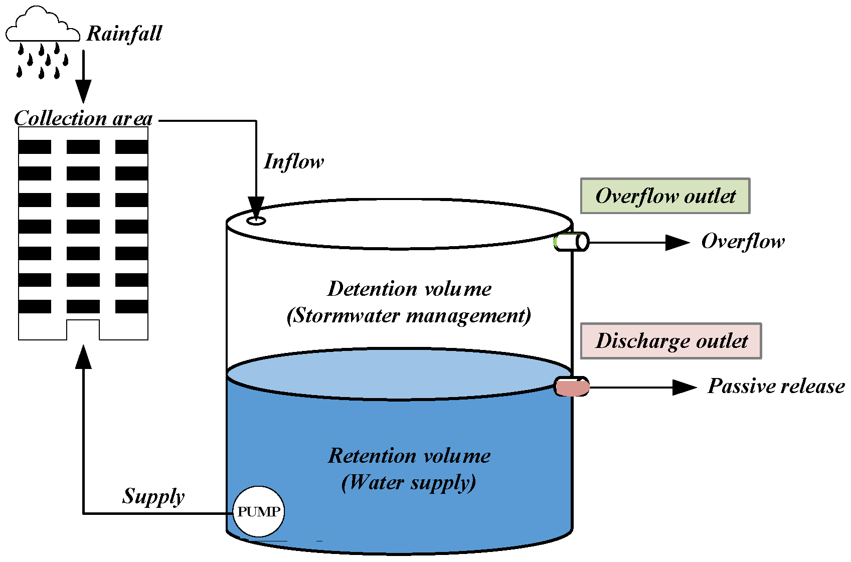
Figure 1. Schematic diagram of the PR-RWHS.
Water 16 02894 g001
Figure 3. Diagram of the discharge outlet locations for PR-RWHS.
Water 16 02894 g003
Figure 4. Illustration of an existing domestic RWHS.
Water 16 02894 g004
Figure 5. Illustration of water budget in the tank of a PR-RWHS.
Water 16 02894 g005
Figure 6. Flow chart of simulation model for PR-RWHS.
Water 16 02894 g006
Figure 8. Illustrative diagram of hydrographs for the conv. RWHS and PR-RWHS. (a) Inflow hydrograph and discharge hydrograph of the conv. RWHS; and (b) inflow hydrograph and discharge hydrographs of both the conv. RWHS and PR-RWHS.
Water 16 02894 g008
Figure 9. Discharge flow analysis for PR-RWHS discharge outlets. (a) Flow rate variations of discharge outlet types and diameters, and (b) flow rate variations of short stub fitting.
Water 16 02894 g009
Figure 10. Radar plot of design storm analysis for the DH with 2-year return period design storm. (a) Peak flow mitigation rate, and (b) peak flow lag time.
Water 16 02894 g010
Figure 11. Radar plot of design storm analysis for the DH with 5-year return period design storm. (a) Peak flow mitigation rate, and (b) peak flow lag time.
Water 16 02894 g011
Figure 12. Radar plot of design storm analysis for the DH with 10-year return period design storm. (a) peak flow mitigation rate, and (b) peak flow lag time.
Water 16 02894 g012
Figure 13. Analysis of peak flow mitigation rate using 2-year, 5-year and 10-year return period design storm for (a) the DH, (b) the FSB, and (c) the ESB.
Water 16 02894 g013
Figure 14. Peak flow mitigation rate of the DH at different locations for potentially hazardous rainfall events. (a) S-HR, (b) L-HR, (c) S-TR, and (d) L-TR.
Water 16 02894 g014
Figure 15. Average peak flow mitigation rate at different locations for probably hazardous rainfall events. (a) DH, (b) FSB, and (c) ESB.
Water 16 02894 g015
Figure 16. Boxplots and incremental analysis of average annual water supply and regulated stormwater release for the DH. (a) Boxplot of scenario 2; (b) incremental analysis of scenario 2; (c) boxplot of scenario 3; and (d) incremental analysis of scenario 3.
Water 16 02894 g016
Figure 17. Boxplots and incremental analyses of average annual water supply and regulated stormwater release for the FSB. (a) Boxplot of scenario 2; (b) incremental analysis of scenario 2; (c) boxplot of scenario 3; and (d) incremental analysis of scenario 3.
Water 16 02894 g017
Figure 18. Boxplots and incremental analysis of average annual water supply and regulated stormwater release for the ESB. (a) Boxplot of scenario 2; (b) incremental analysis of scenario 2; (c) boxplot of scenario 3; and (d) incremental analysis of scenario 3.
Water 16 02894 g018aWater 16 02894 g018b
Table 1. Basic information for selected representative buildings.
Representative Buildings Roof Area (m2)Tank VolumeNumber of FloorsHouseholds on Each FloorNumber of ResidentsWater Demand (m3/Day)
Calculated (m3)Practical (m3)
Detached house (DH)1255.5361130.3
Four-story building (FSB)25013.831542242.4
Eight-story building (ESB)50027.673084969.6
Table 2. Attributes of selected case study scenarios for design storms.
VariablesDHFSBESB
Roof area (m2)125250500
Tank size (m3)61530
Demand (m3/day)0.32.49.6
Rainfall dataThe 2, 5, and 10 year return periods design storm with rainfall duration of 120 min and time resolution of 5 min intervals.
Discharge outlet locationCSFD-0, CSFD-25, CSFD-50, CSFD-75, and CSFD-100
Discharge outlet diameters (mm)5, 10, 15, 20, 25, 30, 35, 40, 45, and 50
Assessment indicatorPeak flow mitigation rate and peak flow lag times
Table 3. Classification of probably hazardous rainfall events.
ClassificationHeavy Rain
(HR)
Torrential Rain
(TR)
Severe Torrential Rain
(STR)
Extreme Torrential Rain
(ETR)
Short-durationAbove 40 mm/h
(S-HR)
Above 100 mm/3 h
(S-TR)
Above 200 mm/3 h
(S-STR)
-
Long-durationAbove 80 mm/24 h
(L-HR)
Above 200 mm/24 h
(L-TR)
Above 350 mm/24 h
(L-STR)
Above 500 mm/24 h
(ETR)
Table 4. Attributes of selected case study scenarios for probably hazardous rainfall events.
VariablesDHFSBESB
Roof area (m2)125250500
Tank size (m3)61530
Demand (m3/day)0.32.49.6
Rainfall dataS-HR, L-HR, S-TR, L-TR, S-STR, L-STR, and ETR events
(1 h interval)
Discharge outlet locationCSFD-0, CSFD-25, CSFD-50, CSFD-75, and CSFD-100
Discharge outlet diameters (mm)The optimal diameter determined by design storms analysis
Assessment indicatorPeak flow mitigation rate
Table 5. Attributes of selected case study scenarios for continuous rainfall simulations.
VariablesDHFSBESB
Roof area (m2)125250500
Tank size (m3)61530
Demand (m3/day)0.32.49.6
Rainfall dataContinuous rainfall data from years 2014–2023 (1 h intervals)
Discharge outlet locationScenario 1CSFD-0 throughout the year
Scenario 2CSFD-0, CSFD-25, CSFD-50, CSFD-75, and CSFD-100 throughout the year
Scenario 3CSFD-0 in dry season and CSFD-0, CSFD-25, CSFD-50, CSFD-75, and CSFD-100 in wet season
Discharge outlet diameters (mm)The optimal diameter determined by design storms and probably hazardous rainfall events verification
IndicatorsWater supply reliability, annual water supply and regulated stormwater release with incremental analysis
Table 6. Feasible discharge outlet diameters for different representative buildings using 2-year, 5-year, and 10-year return period rainfalls.
Representative BuildingFeasible Discharge Outlet Diameter
2-Year
Return Period
5-Year
Return Period
10-Year
Return Period
DH10 mm15 mm 15 mm
FSB-15 mm 20 mm
ESB-15 mm 25 mm
Table 7. The max. peak flow mitigation rates for different combinations of design storm, representative building, and location of discharge outlet for selected outlet diameter = 15 mm.
Design StormRepresentative Buildings
DHFSBESB
conv. RWHSPR-RWHS (1)Difference (2)conv. RWHSPR-RWHSDifferenceconv. RWHSPR-RWHSDifference
2-year83.4%78.4~87.9%−5.0~+4.5%100%89.4~95.0% −5.0~−10.6%100%93.5~97.6%−2.4~−6.5%
5-year53.9%60.8~75.6%+6.9~+21.7%70.5%70.5~86.6%0.0~+16.1%77.8%78.3~92.4%+0.5~+14.6%
10-year38.8%38.8~73.5%0.0~+34.7%49.1%49.1~62.4% 0.0~+13.3%49.1%49.1~70.0%0.0~+20.9%
Note: (1): The numbers are the min. and max. values of average peak flow mitigation rates for different locations of discharge outlet (which excludes CSFD-0) in DH building for the specific design storm. (2): The numbers are min. and max. difference values of average peak flow mitigation rates between the PR-RWHS and conv. RWHS.
Table 8. Data regarding probably hazardous rainfall events from 2014 to 2023.
No.Rainfall TimingDuration (h)AR
(mm)
No.Rainfall TimingDuration (h)AR
(mm)
S-HR events
118 August 2015, 3–6 p.m.491.5613 August 2021, 12–2 p.m.371.5
215 May 2016, 3–7 a.m.567.474 August 2022, 1–3 p.m.346.5
320 May 2019, 6–11 a.m.677.4822–23 May 2023, 5 p.m. (22 May)–12 a.m. (23 May)882.5
426 July 2019, 1–3 p.m.377.0930 June 2023, 1–4 p.m.489.0
521 August 2019, 1–2 p.m.270.51020 August 2023, 12–4 p.m.569.5
L-HR events
18–10 February 2014, 9 p.m. (8 February)–1 a.m. (10 February)2996.01528 September 2019, 1 a.m.–6 p.m.1894.5
228–29 May 2014, 8 p.m. (28 May)–6 p.m. (29 May)2380.51622–24 May 2020, 3 p.m. (22 May)–12 p.m. (24 May)46145.4
35–6 June 2014, 9 p.m. (5 June)–4 p.m. (6 June)21107.01729 May 2020, 12 a.m.–3 p.m.16120
421–22 September 2014, 4 p.m. (21 September)–9 a.m. (22 September)18165.0184 August 2020, 5 a.m.–7 p.m.1390.0
518–19 June 2016, 2 p.m. (18 June)–12 a.m. (19 June)11103.81928 August 2020, 11 a.m.–10 p.m.1295.5
618–19 September 2016, 5 a.m. (18 September)–7 a.m. (19 September)2785.22023–24 July 2021, 10 a.m. (23 July)–12 p.m. (24 July)27138.0
728 September 2016, 2 a.m.–11 p.m.22181.8216–7 August 2021, 8 a.m. (6 August)–7 p.m. (7 August)36147.0
83 June 2017, 7 a.m.–7 p.m.13159.52212 September 2021, 8 a.m.–7 p.m.1286.5
912 October 2017, 5 a.m.–9 p.m.17115.22311–12 October 2021, 12 a.m. (11 October)–10 p.m. (12 October)35119.5
1013–15 October 2017, 7 a.m. (13 October)–12 a.m. (15 October)42163.52428–29 Mar 2202, 1 a.m. (28 Mar)–3 a.m. (29 Mar)2786.5
118–9 January 2018, 1 a.m. (8 January)–5 a.m. (9 January)2994.52525–26 May 2022, 5 a.m. (25 May)–1 a.m. (26 May)21130.5
1210–11 July 2018, 3 p.m. (11 July)–9 a.m. (11 July)19106.02626–27 May 2022, 12 p.m. (26 May)–12 p.m. (27 May)2590.0
1311 June 2019, 1 a.m.–7 p.m.19111.5274 June 2023, 1–7 p.m.7137.0
142–3 July 2019, 1 p.m. (2 July)–4 a.m. (3 July)16138.5
S-TR events
17 January 2017, 3–11 a.m.9149.0422 July 2019, 2–4 p.m.3118.5
22 August 2017, 12–2 p.m.3100.5523 June 2023, 1–4 p.m.4123.0
38 September 2018, 3–9 p.m.7144.5610 August 2023, 2–5 p.m.4114.5
L-TR events
17–9 August 2015, 8 p.m. (7 August)–12 a.m. (9 August)17318.9315–17 October 2022, 8 p.m. (15 October)–4 a.m. (17 October)33269.0
227–29 September 2015, 4 p.m. (27 September)–2 a.m. (29 September)35224.9
L-STR events
120–21 May 2014, 9 a.m. (20 May)–8 p.m. (21 May)36411.5
Table 9. The average peak flow mitigation rates for different potentially hazardous rainfall events, representative buildings, and locations of discharge outlet for the selected outlet diameter = 15 mm.
Rainfall Event LevelsRepresentative Buildings
DHFSBESB
conv. RWHSPR-RWHS (1)Difference (2)conv. RWHSPR-RWHSDifferenceconv. RWHSPR-RWHSDifference
S-HR16.6%32.6~44.6%+16~+28.0%51.1%65.5~73.3%+14.4~+22.2%92.4%78.4~85.2%−7.2~−14.0%
S-TR20.8%28.9~54.7%+8.1~+33.9%47.0%52.9~65.4%+5.9~+18.4%48.6%49.7~58.4%+1.1~+9.5%
L-HR9.8%8.6~20.6%−1.2~+10.8%30.4%45.5~48.3%+15.1~+17.9%45.1%58.0~61.5%+12.9~+16.4%
L-TR0.0%6.7~20.5%+6.7~+20.5%0.0%0.0~32.1%0.0~+32.1%7.0%7.0~9.7%0.0~+2.7%
Note: (1): The numbers are the min. and max. values of average peak flow mitigation rates for the different locations of discharge outlets (which excludes CSFD-0) in the DH building for the specific rainfall even level. (2): The numbers are min. and max. difference values of average peak flow mitigation rates between the PR-RWHS and conv. RWHS.
Table 10. Statistical characteristics of annual water supply reliability and average annual water supply reliability of the DH for different scenarios and locations of discharge outlets.
Water 16 02894 i001LocationsAverage Annual Water Supply Reliability
Scenario 1
(A)
Scenario 2
(B)
Difference
(A − B)
Scenario 3
(C)
Difference
(A − C)
CSFD-074.8%74.8%-74.8%-
CSFD-2574.8%71.6%−3.2%74.4%0.4%
CSFD-5074.8%67.7%7.1%73.3%1.5%
CSFD-7574.8%53.4%21.4%66.1%8.7%
CSFD-10074.8%2.0%72.8%41.8%33.0%
Table 11. Statistical characteristics of annual water supply reliability and average annual water supply reliability of the FSB for different scenarios and locations of discharge outlets.
Water 16 02894 i002LocationsAverage Annual Water Supply Reliability
Scenario 1
(A)
Scenario 2
(B)
Difference
(A − B)
Scenario 3
(C)
Difference
(A − C)
CSFD-045.5%45.5%-45.5%-
CSFD-2545.5%41.8%3.7%43.3%2.2%
CSFD-5045.5%36.2%9.3%39.9%5.6%
CSFD-7545.5%28.9%16.6%35.0%10.5%
CSFD-10045.5%0.03%45.47%22.3%23.2%
Table 12. Statistical characteristics of annual water supply reliability and average annual water supply reliability of the ESB for different scenarios and locations of discharge outlets.
Water 16 02894 i003LocationsAverage Annual Water Supply Reliability
Scenario 1
(A)
Scenario 2
(B)
Difference
(A − B)
Scenario 3
(C)
Difference
(A − C)
CSFD-025.4%25.4%-25.4%-
CSFD-2525.4%24.0%1.4%24.3%1.1%
CSFD-5025.4%21.6%3.8%22.5%2.9%
CSFD-7525.4%18.1%7.3%20.1%5.3%
CSFD-10025.4%4.0%21.4%13.4%12.0%
Disclaimer/Publisher’s Note: The statements, opinions and data contained in all publications are solely those of the individual author(s) and contributor(s) and not of MDPI and/or the editor(s). MDPI and/or the editor(s) disclaim responsibility for any injury to people or property resulting from any ideas, methods, instructions or products referred to in the content.