1. Introduction
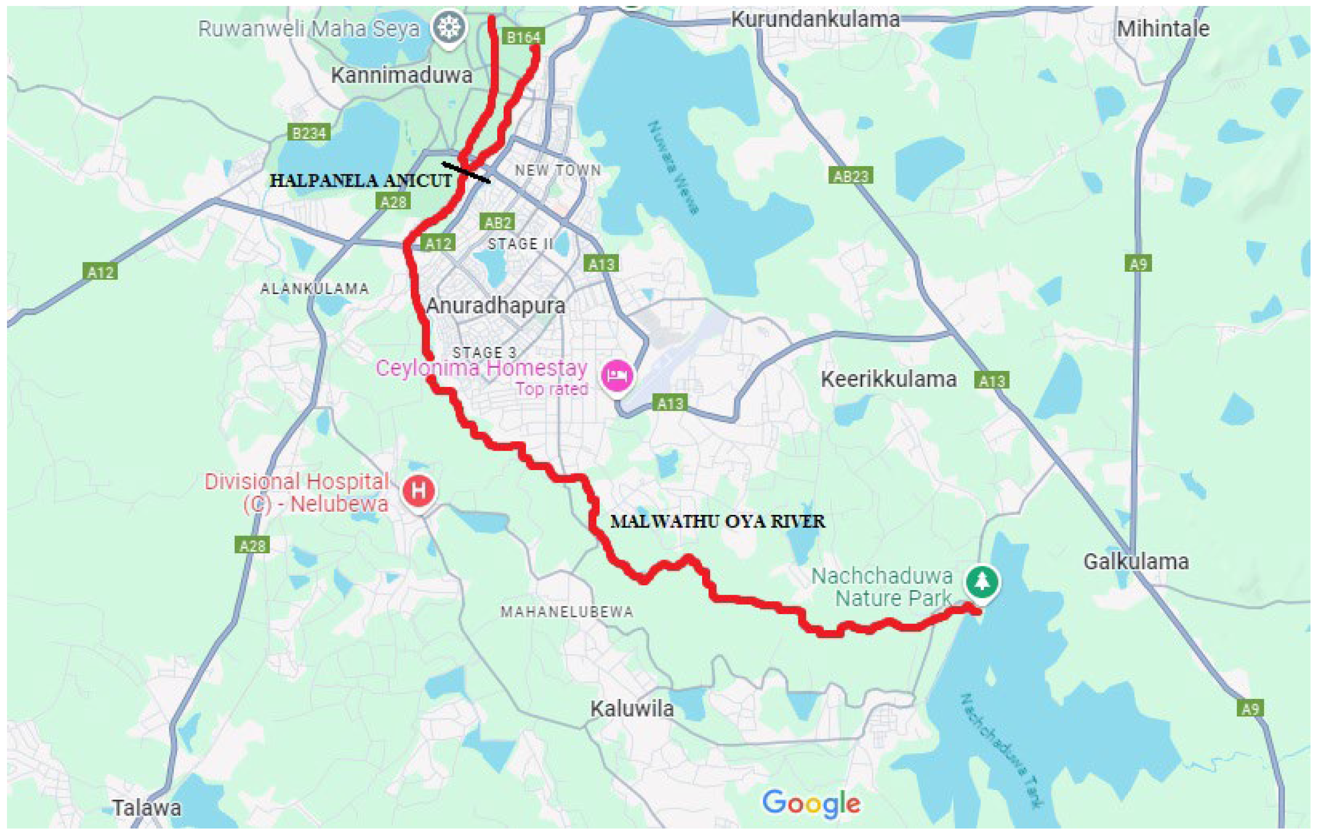
The Malwathu Oya River, depicted in
Figure 1, is the second longest river in Sri Lanka, stretching approximately 164 km from its source in the Ritigala Mountain range in the North Central Province to its mouth at the Gulf of Mannar near Vankalai [
1]. This seasonal river, which winds through paddy fields and forests, plays a critical role in providing water resources essential for the agricultural and daily needs of local communities [
2,
3]. The river basin covers an extensive area of 3284 square kilometers, with a length of 125 km, a width reaching up to 40 km, and an average elevation of 85.5 m above sea level [
4,
5]. Annual rainfall in the basin averages 1223 mm, which is crucial for sustaining the river’s flow throughout the year [
6]. The Ritigala Mountain range, featuring four prominent peaks, including one exceeding 900 m in height, is the primary source area, facilitating the continuous replenishment of this vital waterway [
7].
Malwathu Oya plays a crucial role in irrigation, sustaining the livelihoods of local farmers by providing essential water resources for cultivating a variety of crops, including rice and vegetables. This river is vital to the region’s agricultural economy and also supports fishing activities, which contribute significantly to food security and income generation for surrounding communities.
Table 1 presents further details about the Malwathu Oya River.
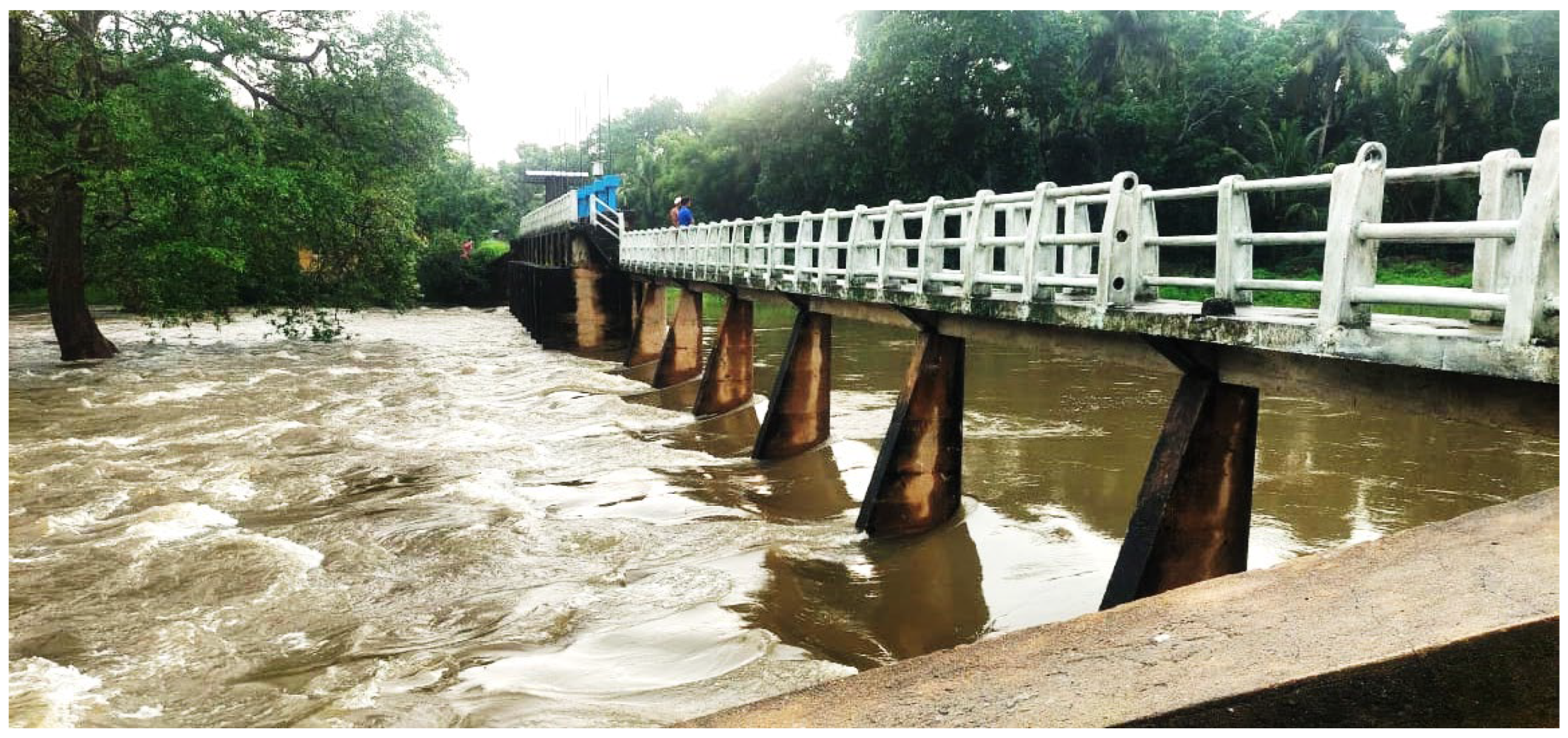
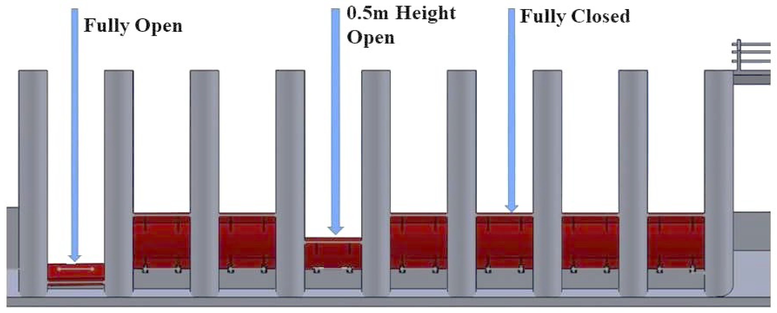
In 2002, the Irrigation Department initiated the design and construction of the Halpan Ela Anicut across the Malwathu Oya River, as illustrated in
Figure 2. This structure was designed to divert water to the surrounding paddy fields, thereby supporting local agriculture [
8]. The Halpan Ela Anicut, which includes eight regulator gates, has been instrumental in distributing water to both smaller tanks and a significant area of approximately 4.05 square kilometers of paddy fields [
9,
10]. For local farmers, this hydraulic infrastructure is vital, providing a reliable water source necessary for year-round farming and supporting the region’s agrarian economy [
11]. The anicut has eight mild steel spindle gates, each measuring 1676 mm by 1981 mm, which are operated by a worm gear hoisting system for precise water flow control. The structure is 104 feet long and supported by strong concrete piers that measure 3 feet by 11 feet, providing stability and durability. The design includes key elevation points: the Full Supply Level (FSL) is at 244.5 feet, the High Flood Level (HFL) at 253 feet, and the Gate Sill Level at 239 feet. The trench bottom is at 257 feet, the piers rise to 260.5 feet, and the bridge level is at 258 feet. This design shows the Irrigation Department’s commitment to improving water management for both agriculture and flood control. The Halpan Ela Anicut is vital for the local irrigation system and boosting farm productivity. Despite its benefits, the Malwathu Oya River is prone to frequent flooding. Records from the past 12 years indicate that the river has experienced an average of 14 minor floods annually, causing considerable crop damage and disruption to local communities [
8,
12].
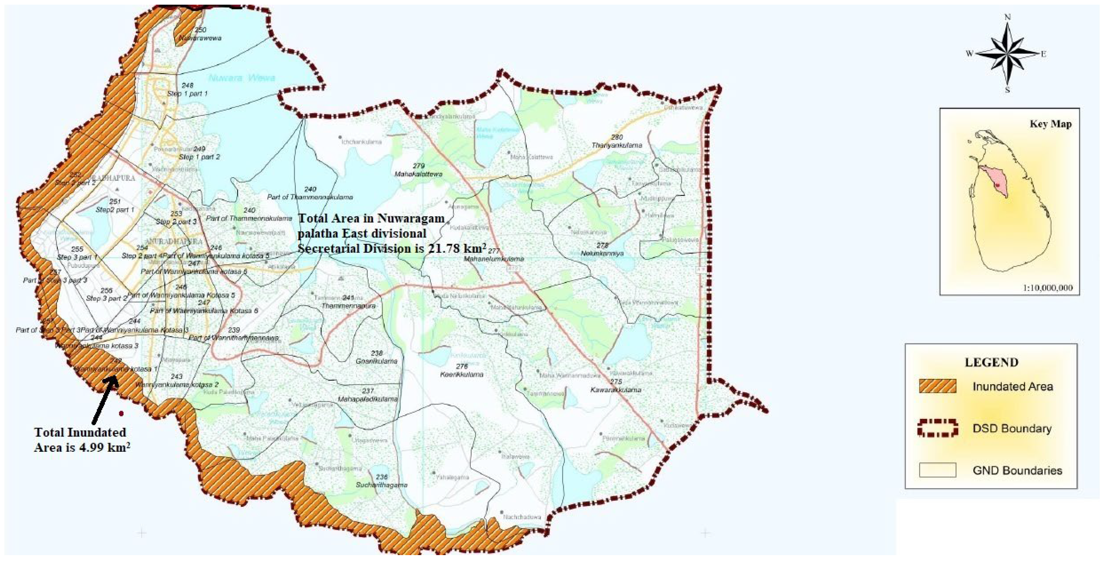
Persistent flooding has notably affected Anuradhapura City, home to significant Buddhist religious sites, and the residential areas upstream from the anicut. In response, the Irrigation Department has conducted detailed field inspections and analyzed historical data to develop proactive measures aimed at mitigating flooding in the upper catchment area of the Halpan Ela Anicut, as depicted in
Figure 3 [
1,
13].
Recent advancements in gate technology and flood management strategies offer new ways to address these problems. One notable development is the flap gate, which operates automatically. Flap gates open when water pressure rises and close when the pressure decreases. This feature makes them effective for flood control, allowing smooth water flow during high water levels while preventing backflow. They are also low-maintenance and durable, making them ideal for managing the Malwathu Oya River’s flow. Nature-based flood management solutions (NBSs) are also gaining interest. Strategies such as constructed wetlands, vegetated buffer zones, and floodplain restoration can help slow down and absorb floodwaters, reducing pressure on gate systems [
14]. These approaches offer a sustainable method for managing floods, particularly in flood-prone areas such as the Malwathu Oya River basin.
Smart gate systems that use sensor technology and predictive flood models are another advancement in flood control. These systems monitor water levels in real-time and automatically adjust the gates to improve water flow management (Lee & Kim, 2023). When combined with predictive models such as HEC-RAS and SWMM, smart gates can forecast potential flood events and adjust accordingly to minimize damage [
15]. Lastly, integrating Flood Early Warning Systems (FEWSs) enhances flood preparedness. These systems utilize satellite data and remote sensing to monitor weather patterns and predict flood risks [
16]. When linked with smart gate systems, FEWSs can trigger timely gate adjustments to reduce flood damage and improve overall flood management. By adopting these modern gate technologies and flood management strategies, the Halpan Ela Anicut can enhance its flood handling capacity, reduce maintenance costs, and improve overall water management. These advancements will help the region manage recurring flood challenges while ensuring sustainable water use for agriculture
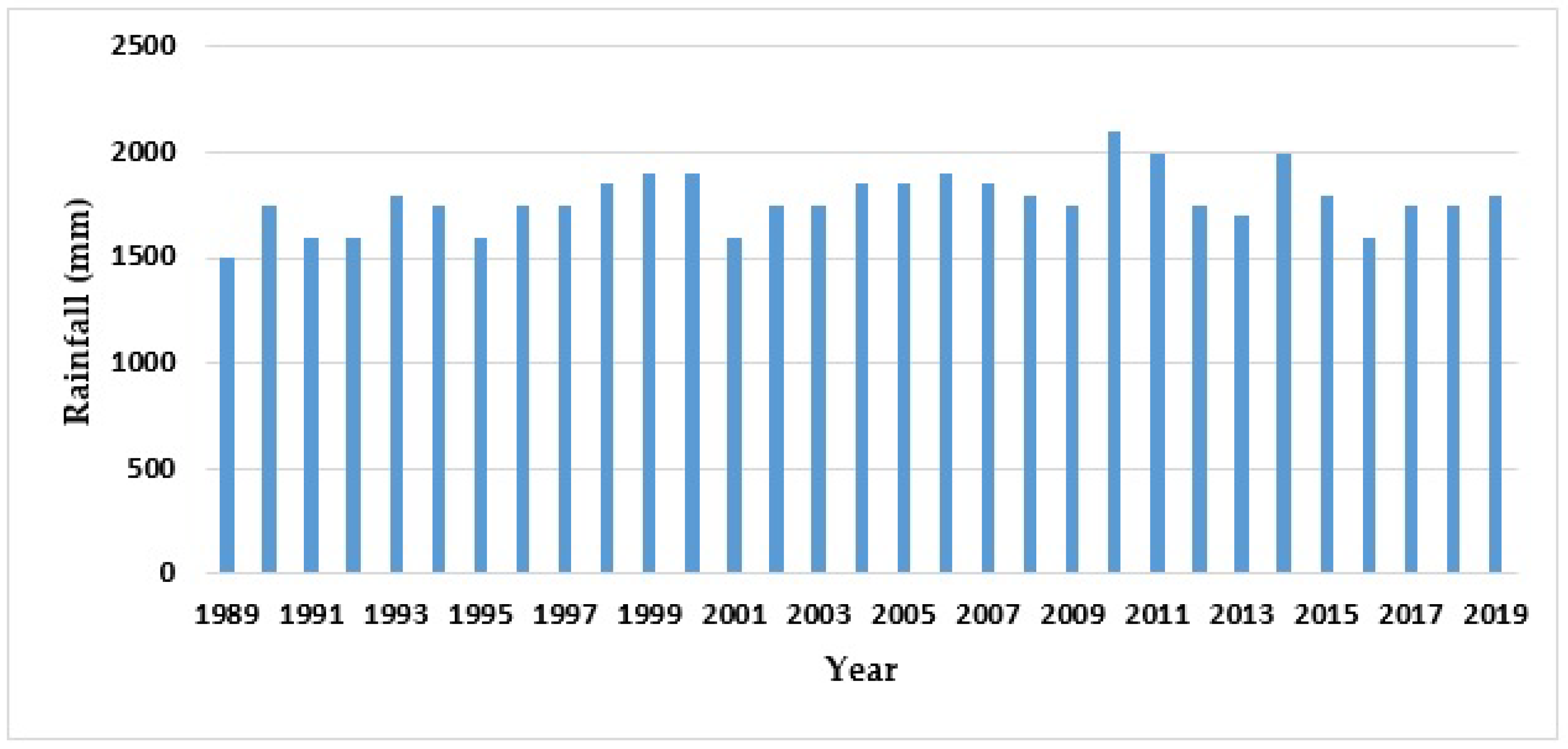
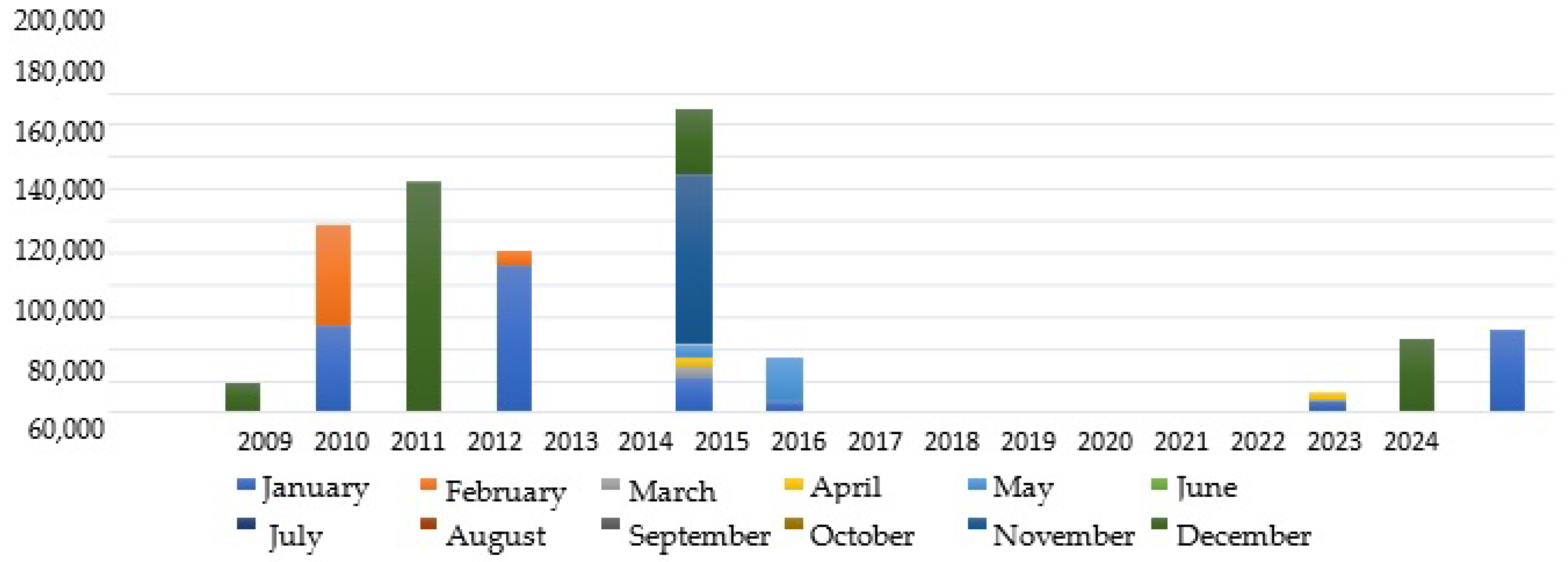
Figure 4 shows the changes in the annual rainfall of Sri Lanka from 1989 to 2019. Furthermore, the spatial and temporal variability of rainfall can be identified, all of which usually show a variety of variance patterns, but overall, there is a tendency for rainfall to increase [
4]. The climate has undergone significant changes since the design of the Anicut in 2002 by the Irrigation Department. During its initial planning phase, the department considered the climate from that period. However, the effects of climate change have altered these conditions. Presently, heavy rainfall has intensified, leading to a higher river water quantity compared to previous years. Consequently, it is imperative to modify the gate types of the Anicut to prevent inundation of the upper reach area.
The global climate system has undergone unprecedented changes due to global warming since the 1950s [
17], and continuous climate change will affect many countries, increasing the risk of flood and drought and other natural disasters, which will ultimately adversely affect the agricultural economy.
Due to climate change, river water levels have increased significantly, surpassing the levels of the past 20 years. This is evident from the data depicted in the graph as shown in
Figure 5, which illustrates the spillage data of the Nachchaduwa tank over the past decade. As the volume of water spilling from the upper catchment tanks increases, so does the water volume of the Malwathu Oya River.
The specific objectives of this research are to design and enhance a water level control gate system for the Malwathu Oya River to mitigate the risk of flooding in Anuradhapura City, particularly in the frequently affected Nanupa Divisional Secretariat Division. The study will address the limitations of the existing gate system at the Halpan Ela Anicut, including flow disturbances caused by the gate skin barrier even when fully opened, the slow operational response, and obstructions from debris and aquatic vegetation, all of which hinder effective flood management. Additionally, the study will examine factors such as rainfall patterns and river flow rates to better understand the causes of flooding. A new gate system will be designed to improve water level control and maintain water flow, and its effectiveness will be evaluated [
18]. This research involves reviewing the current system’s limitations, analyzing environmental factors, and designing an optimized gate system that offers a more efficient solution for flood control in Anuradhapura.
This research is limited to designing an effective gate system for Halpan Ela Anicut, without addressing all aspects of flood management in Malwathu Oya River. The proposed gate system’s effectiveness may vary due to external factors such as climate change, land-use changes, and socio-economic dynamics, which are not fully accounted for in the study. This research does not comprehensively address all possible flood scenarios and their impacts on Anuradhapura City and its surroundings. Additionally, this study relies on assumptions and simplifications in modeling and analysis, which could affect the accuracy and reliability of the findings.
2. Methodology
Currently, the existing hydraulic structure relies on regulator gates for managing water levels. During heavy rainfall, particularly when precipitation exceeds 150 mm, the Malwathu Oya River encounters significant challenges, leading to flooding in its upper reach area [
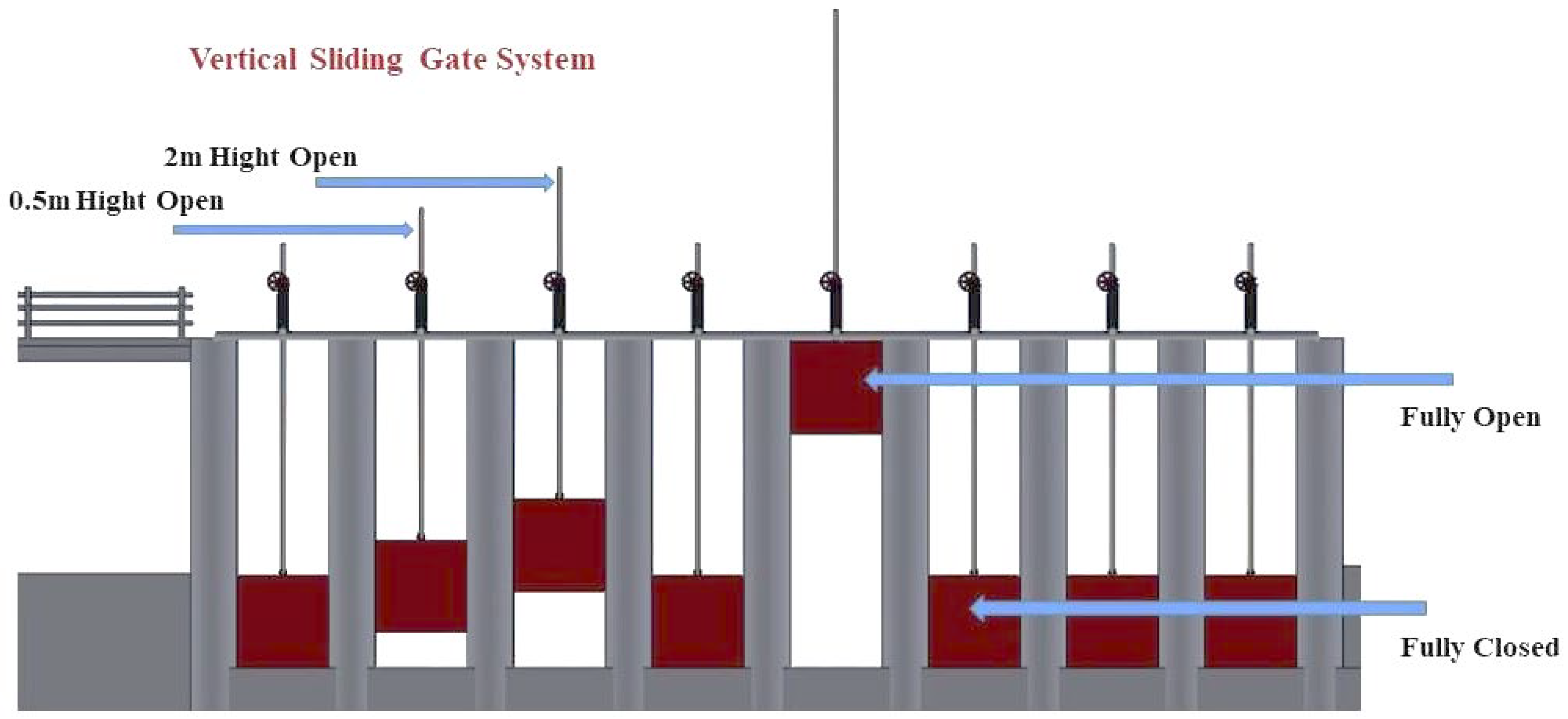
19]. The current gate system, which comprises eight gates each measuring 4 m² and a combined surface area of 32 square meters, struggles to effectively release floodwaters. This inefficiency causes blockages and disruptions in the downstream water flow from the anicut [
20,
21]. The slow operation of these gates exacerbates the situation, underscoring the urgent need for a more responsive system to address sudden increases in water levels [
22].
The remote and challenging terrain further complicates access to and operation of these gates during emergencies, potentially delaying flood control efforts [
23]. To enhance flood management, it is essential to develop a more efficient gate system capable of rapid operation, reducing reliance on specialized personnel, and equipped with alternative power sources to mitigate the impact of potential power outages [
24]. When selecting a gate for a hydraulic structure, it is crucial to align the gate’s features with the specific operational needs [
25]. Factors to consider include the discharge capacity, ability to handle floating debris, and hydraulic regulation [
26]. For large discharge spillways, underflow gates such as segment and fixed-wheel gates are optimal. Gates without lateral slots or projections such as segment, flap, sector, and drum gates offer greater efficiency [
27,
28]. Overflow gates, including flap, drum, and sector types, are effective for precise water level regulation and managing debris or ice with minimal flow disruptions [
29]. Additionally, double-leaf fixed-wheel gates or composite gates (e.g., segment or fixed-wheel gate combined with a flap) provide effective solutions. Gates such as segment, sector, drum, bear-trap, and flap can be hydraulically regulated using floats and counterweights, eliminating the need for mechanical hoists and maintaining constant pool levels for flood protection, especially in harsh climates or difficult access areas [
30].
Given these considerations, flap gates are identified as the most suitable option for the Malwathu Oya River. Flap gates efficiently manage floating debris by lowering the upper leaf or flap for smaller flows and fully raising both parts for larger discharges, ensuring effective flow management [
18,
27].
Weirs represent a crucial category of hydraulic structures for managing open watercourses. Various weir designs exist, depending on the main regulation gate structure intended for water storage. A hinged-leaf main regulation gate, with one end suspended and anchored at two points, has been designed for the 2 m wide dike opening at the Halpan Ela anicut section of the Malwathu Oya River [
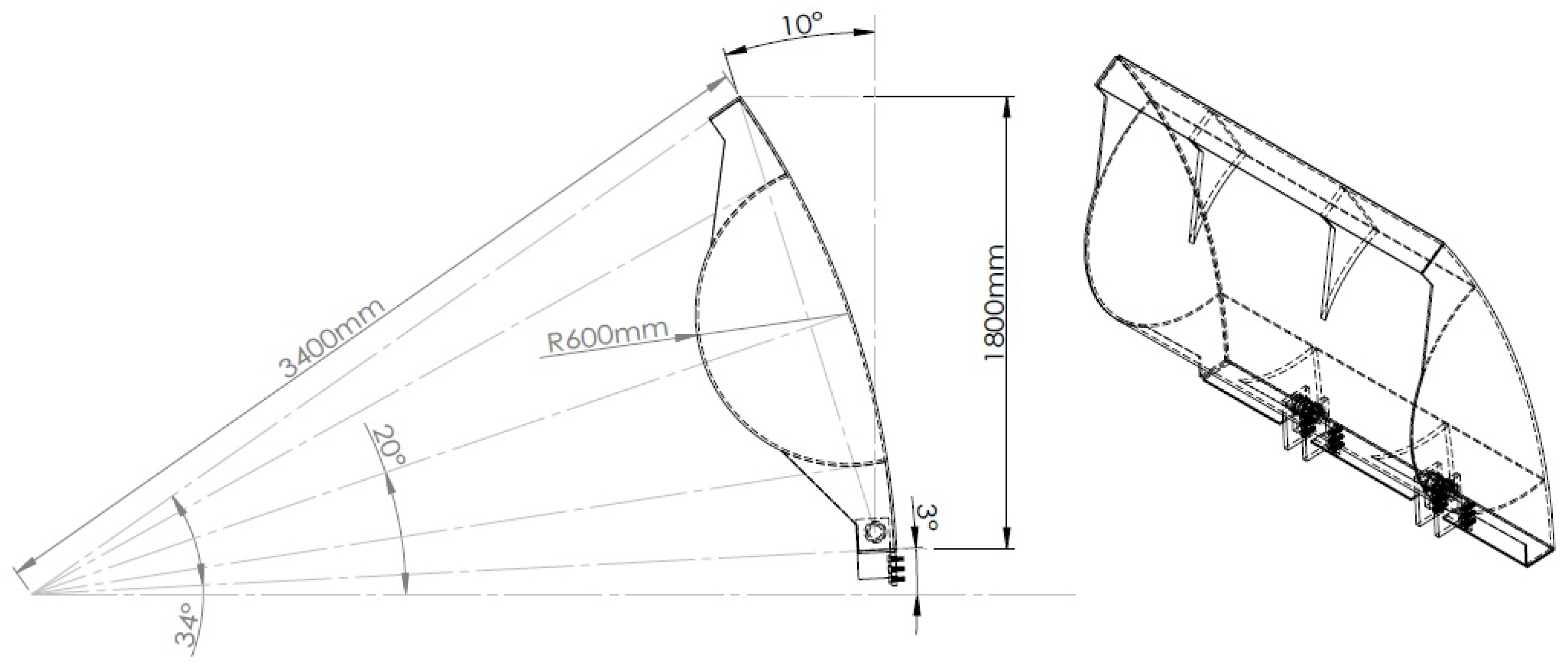
31]. This paper includes an analysis of the gate frame, the specialized fish-belly beam, and the gate leaf, as depicted in the perspective drawing in
Figure 6. The gate, which is suspended at one end, is operated by a hydraulic cylinder, an oil pressure-operated device, for efficient regulation of water levels.
The principal dimensions of the gate leaf are as follows: height in the extreme position (inclined at 10°) is 1.8 m, length is 2 m, and the spacing of the anchors is 0.46 m. The general layout of the main flap gate, including anchoring and other accessories, is shown in
Figure 7. The loads and effects have been considered for various gate leaf positions.
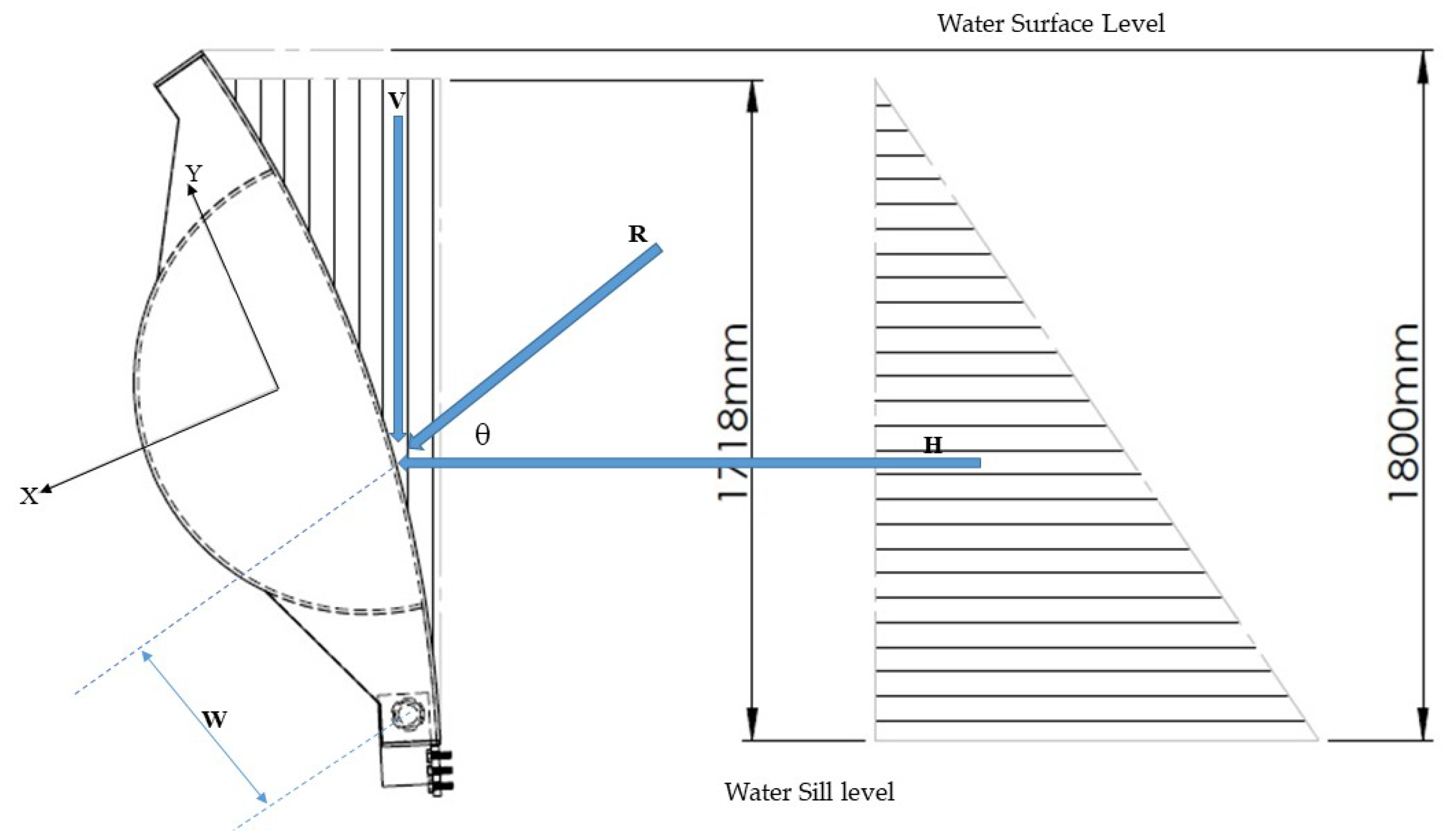
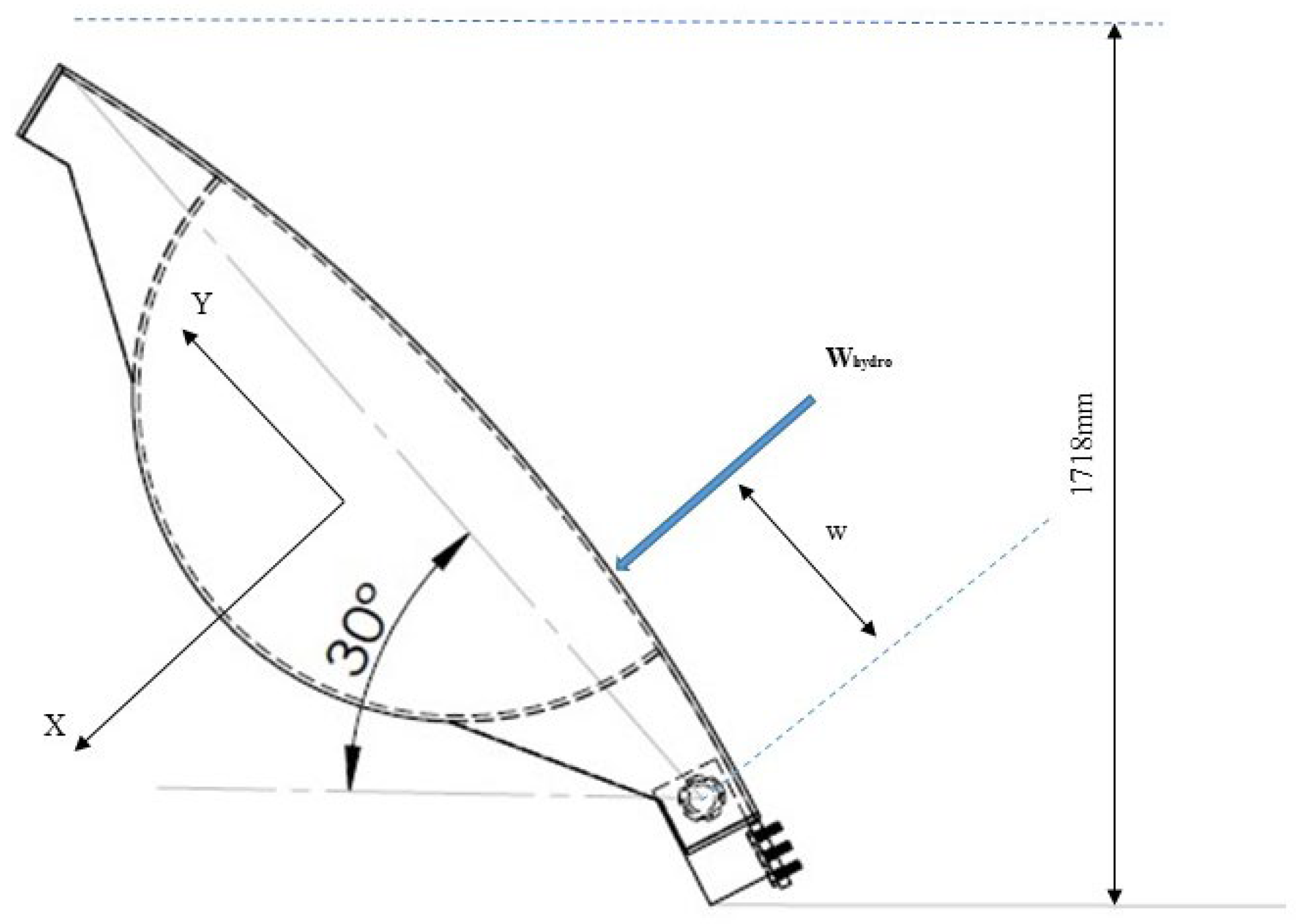
Figure 8 illustrates the hydrostatic water load on the flap gate, while
Figure 9 shows the direction of the resultant force.
The permanent load includes the dead load of the gate and the weight of the silt deposited on the underwater fish-bellied part of the gate [
32]. The weight of the hinged gate leaf is Gt = 7.28 kN. The silt deposited is assumed to be 3 kg in the fish-bellied and frame part of the leaf. Then, the total weight of the gate leaf (G) can be evaluated by using Equation (1) [
33].
The dead load of the gate leaf is “g” and can be found as mentioned in Equation (2), and the dead load will be assumed to be concentrated at the actual cross section centroid.
The water thrust on radial-type gates passes through the center of the skin plate’s curvature. To simplify the calculations, the water thrust is broken down into the horizontal and vertical components. The provided formulas are generic and can be used for different types of gates, such as weir gates, submerged segment gates, sector gates, and flap gates with radial skin plates [
26]. The horizontal component and vertical component of the water thrust can be evaluated by using Equations (3) and (4).
The vertical component is:
where γ = specific weight of water = 9.81 kN/m
3, B = side seal span, R = skin plate radius (measured on the wet surface), H = maximum headwater on sill, h = gate sealing height, D
m = difference between the elevations of the water level and the center of curvature of the skin plate.
The dead load will be assumed to be concentrated at the centroid of the actual cross section. The effect of the dead load will be expressed by the moment about the hinge Mg = gk (kN/m), where k is the lever of the weight for different positions of the leaf. The hydrostatic water load and direction of the resultant thrust during gate operation can be evaluated using Equations (5) and (6). The magnitude (
W) and direction (β) of the resultant water thrust are calculated as follows,
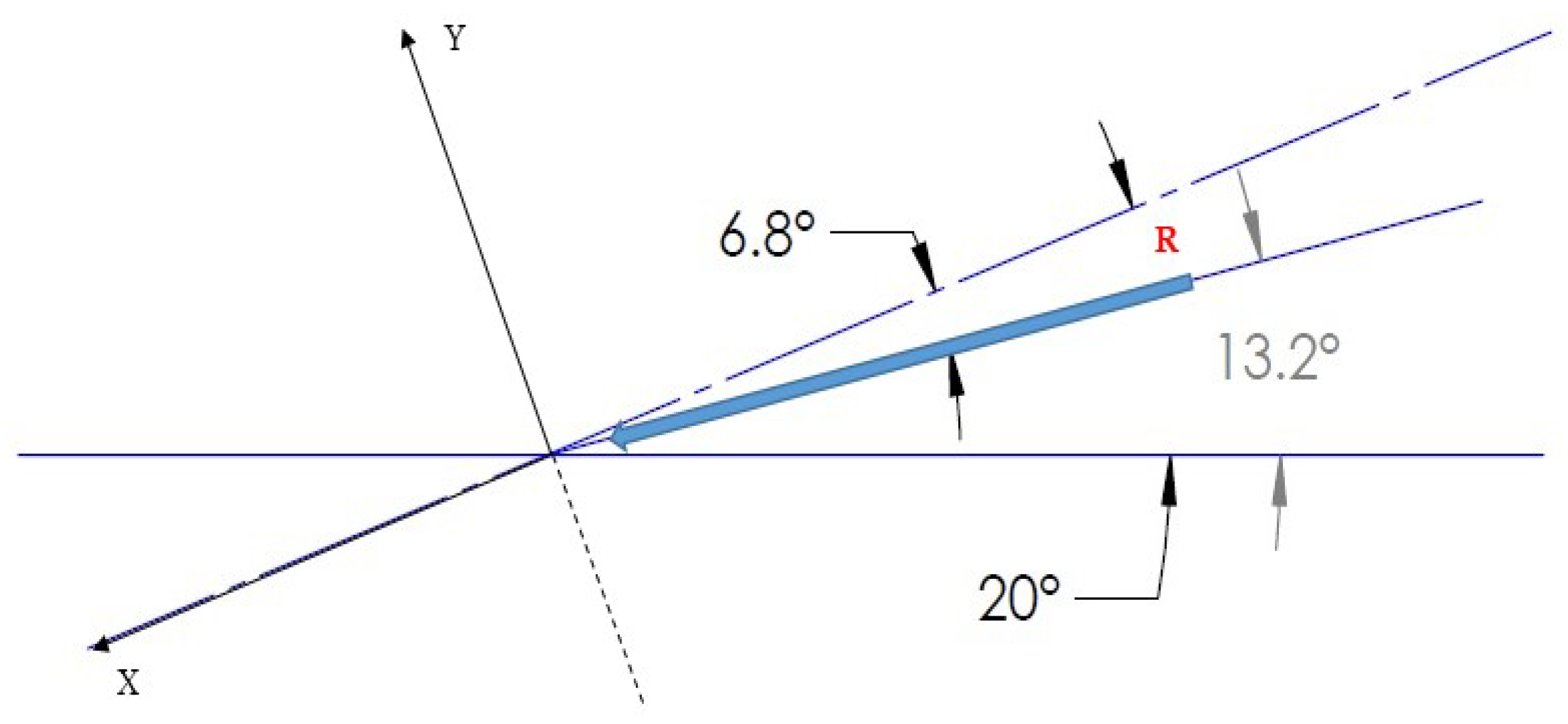
α = 80°, impounding head = 1718 mm, tail water level = 0 (assumed), H = 14.5 kN/M, V = 3.4 kN/m, resultant water thrust = 14.89 kN/m, and direction = 13.2°.
The distance of the influence line (
w) of the resultant force from the line of hinges can be found using Equation (7) [
26].
The resultant force (R) and the dead weight components along the X and Y axes can be determined using Equations (8)–(11) as follows,
After evaluating the above equations, it was determined that € = 6.8°, α = 80°, Rx = 14.8 kN/m, Ry = 1.8 kN/m, Gx = 1.76 kN/m, and Gy = 4.8 kN/m.
The moment about the line through the hinges is,
where w = distance of the influence line of the resultant force from the line of hinges. The hydrodynamic water load acting on the hinged gate leaves is produced by the effect of the water flow. The maximum hydrodynamic water load on one meter of leaf can be calculated by using Equations (13) and (14) as follows,
where s = width of the gate leaf (m), hmax = hydrostatic head in the case of maximum storage (m), the hydrodynamic water load for different load positions is expressed by the resultant force W
hydr, and the moment about the hinged line M
hydr can be evaluated using Equation (15) as follows,
where w represents the distance of the influence line, as shown in
Figure 10, from the resultant to the hinge line. Using Equations (12) through (15), we calculated the hydrodynamic water load at a leaf position of α = 30°. The results are shown in
Table 2.
In the case of an upright (extreme) leaf position (α = 80°), the hydrostatic water load can be evaluated using Equations (16)–(19) as mentioned above, in operating conditions without an ice load (safety factor 1.2)
In the case of the critical (α = 30°) hydrodynamic load
Using Equations (16) through (19), we calculated the hydrodynamic water load at a leaf position of α = 80° and α = 30°. The results are shown in
Table 3.
The hoist force can be calculated from the hinge line moment using Equation (20). Its variation with the gate leaf position is conveniently represented in
Figure 11 and as follows,
where ∑ W = resultant water load (kN), G = dead load (kN),
F = hoist force (kN), α = angle of inclination of the gate leaf, ranging from 80° to 0°. Based on the design condition mentioned in
Table 4, different parameters related to the gate were calculated.
Based on the previous calculations, a detailed 3D model of the gate has been created using SolidWorks software 2020, as shown in
Figure 12. This model includes components such as pivots, horizontal beams, and skin plates. Using SolidWorks 2020 allows for precise detailing and structural analysis, ensuring the gate’s design is strong and optimized. This approach helps thoroughly evaluate the gate’s performance and make necessary adjustments to meet specifications.
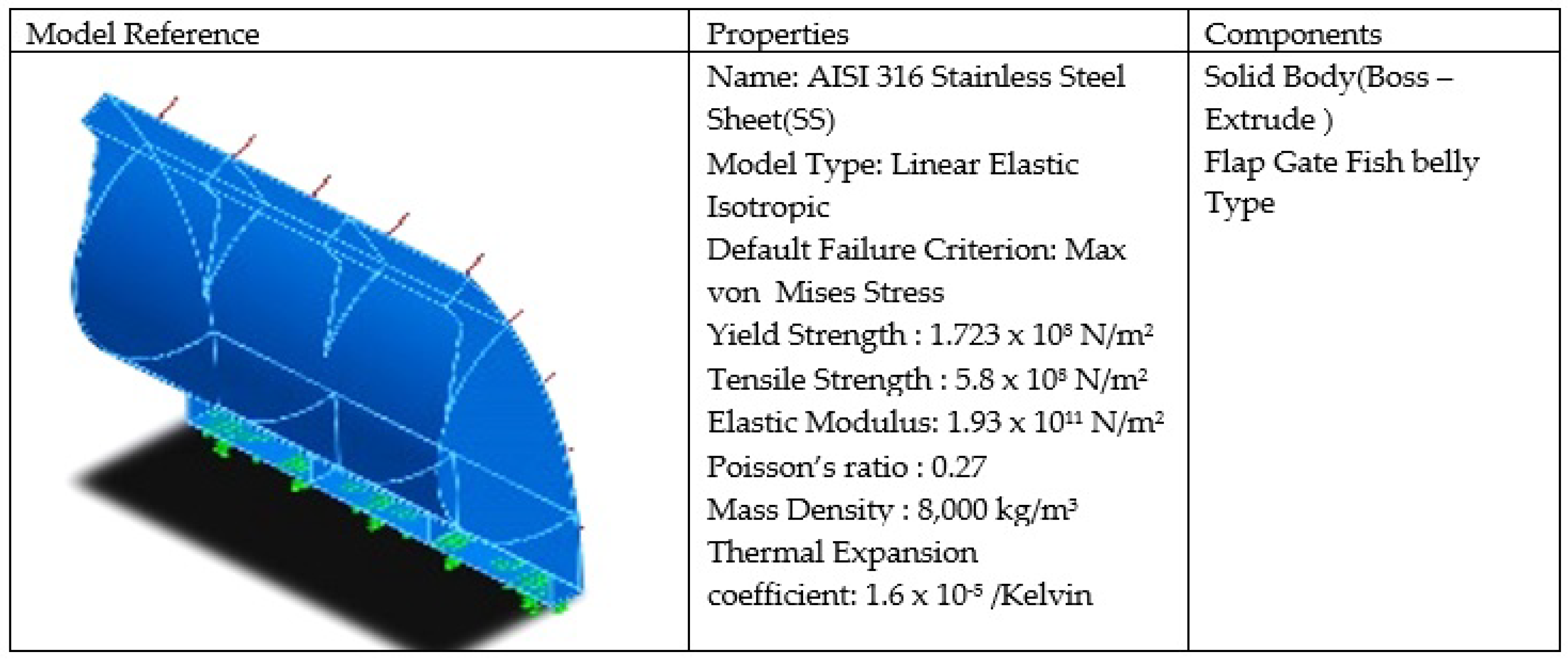
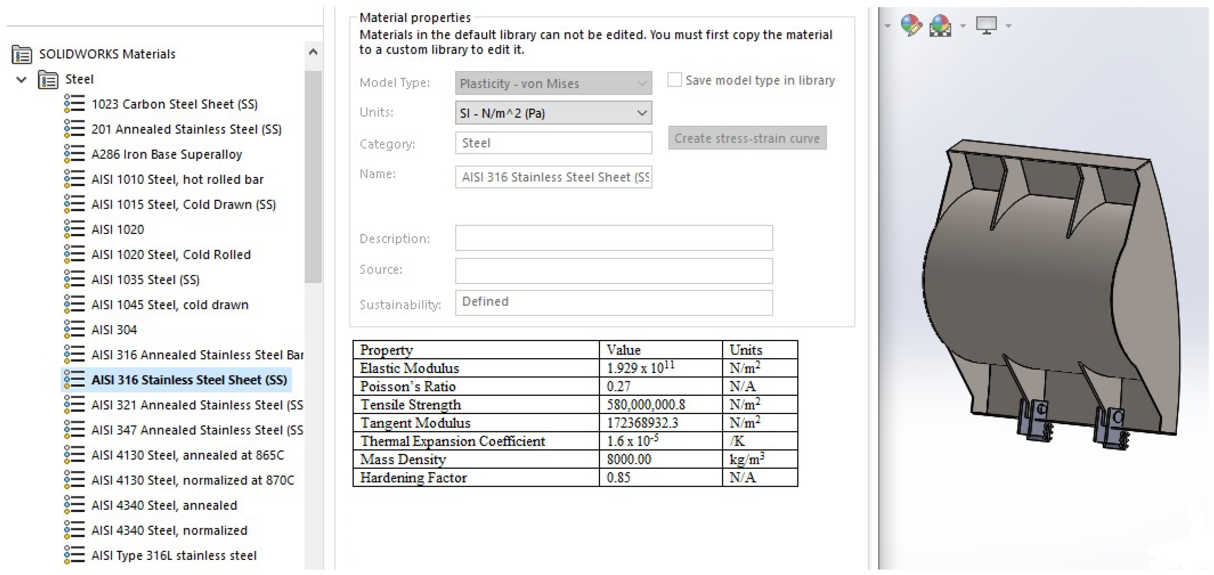
The materials were chosen for each part of the flap gate. For example, steel or composite materials were used for the gate, and rubber or polymers were selected for the seals. The material properties such as the strength, density, and elasticity were considered to make the simulations realistic as shown in
Figure 13.
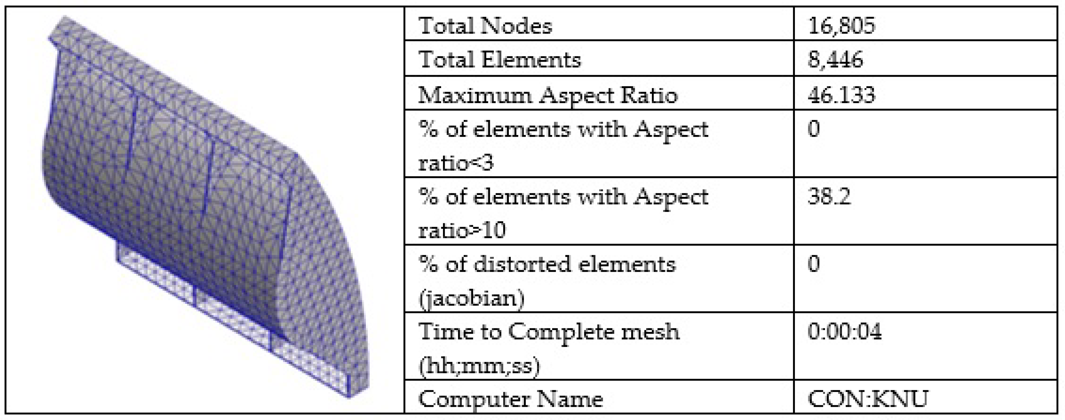
The structural analysis of the gate was performed using Finite Element Analysis (FEA) in SolidWorks 2020. The gate and its parts were meshed, with smaller elements in areas such as hinges to capture more detail. Mesh generation is an important step before simulation of the design [
34]. A mesh is the division of a body or design into smaller elements as shown in
Figure 14 to make the analysis accurate and efficient. The finer the mesh is, the better the results. The simulations were performed on fine mesh. Fatigue analysis was also performed to predict how long the gate would last under repeated use.
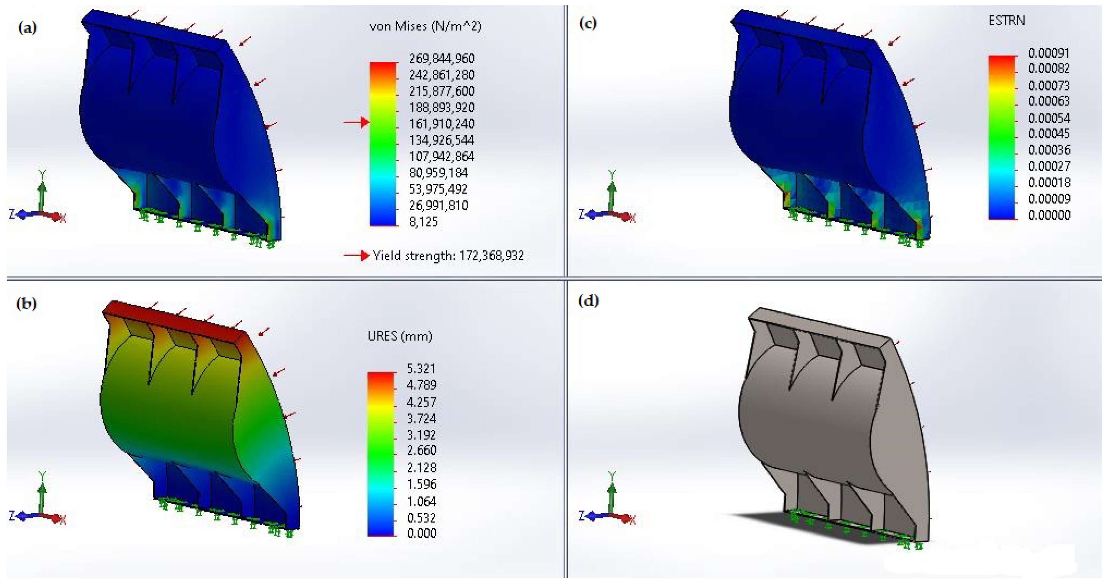
Based on the calculated data provided above, we can conduct simulations to evaluate the structural integrity of the gate using SolidWorks 2020 software. This powerful tool allows for precise analysis, ensuring the gate’s design can withstand various conditions and stresses it may encounter during operation. Through simulation, we can identify potential weaknesses or areas for improvement as shown in
Figure 15, ultimately enhancing the gate’s performance and reliability.
Figure 15a shows the von Mises stress distribution in the gate structure, which helps predict where the material might fail under complex loads. Higher stress areas are highlighted, indicating potential weak points. The color gradient helps visualize these stress concentrations, allowing for targeted design improvements.
Figure 15b shows the equivalent strain (ESTRN) in the gate structure, indicating how much the material has been stretched or compressed. The simulation results display the strain distribution, with higher strain areas highlighting significant deformation. This information is essential for assessing the flap gate’s ductility and performance under load. The deformation scale is 37.6596.
Figure 15c presents the resultant displacement (URES) of the gate structure.
Figure 15d illustrates the initial 3D model developed using Solid Works software prior to any simulation processes. The resultant displacement measures the total movement of points within the structure due to applied loads.
Figure 15a–c highlight the areas experiencing the most significant displacements, which is essential for evaluating the stability and rigidity of the gate. Understanding these displacement patterns helps ensure that the gate can maintain its integrity under operational conditions.
After conducting a comprehensive structural analysis using SolidWorks 2020 software on the entire flap gate, encompassing all its components, we observed no displacement and ensured that the stress–strain factor did not exceed permissible limits. Based on these findings, we can confidently conclude that this structure is suitable.
SolidWorks’ parametric modeling capabilities were utilized to explore a wide range of design alternatives for the gate system. This allows for the rapid iteration and optimization of key design parameters such as the gate dimensions, shape, and materials. Structural analysis was conducted within SolidWorks 2020 to validate the integrity and stability of the optimized gate system designs under various loading conditions, including hydrostatic pressure from floodwaters. This ensures that the selected design meets safety standards and performance requirements. Optimization algorithms were implemented within Solid Works 2020 to systematically explore the design space and identify optimal configurations based on predefined objectives and constraints. This could involve maximizing flood control effectiveness while minimizing material usage or construction costs.
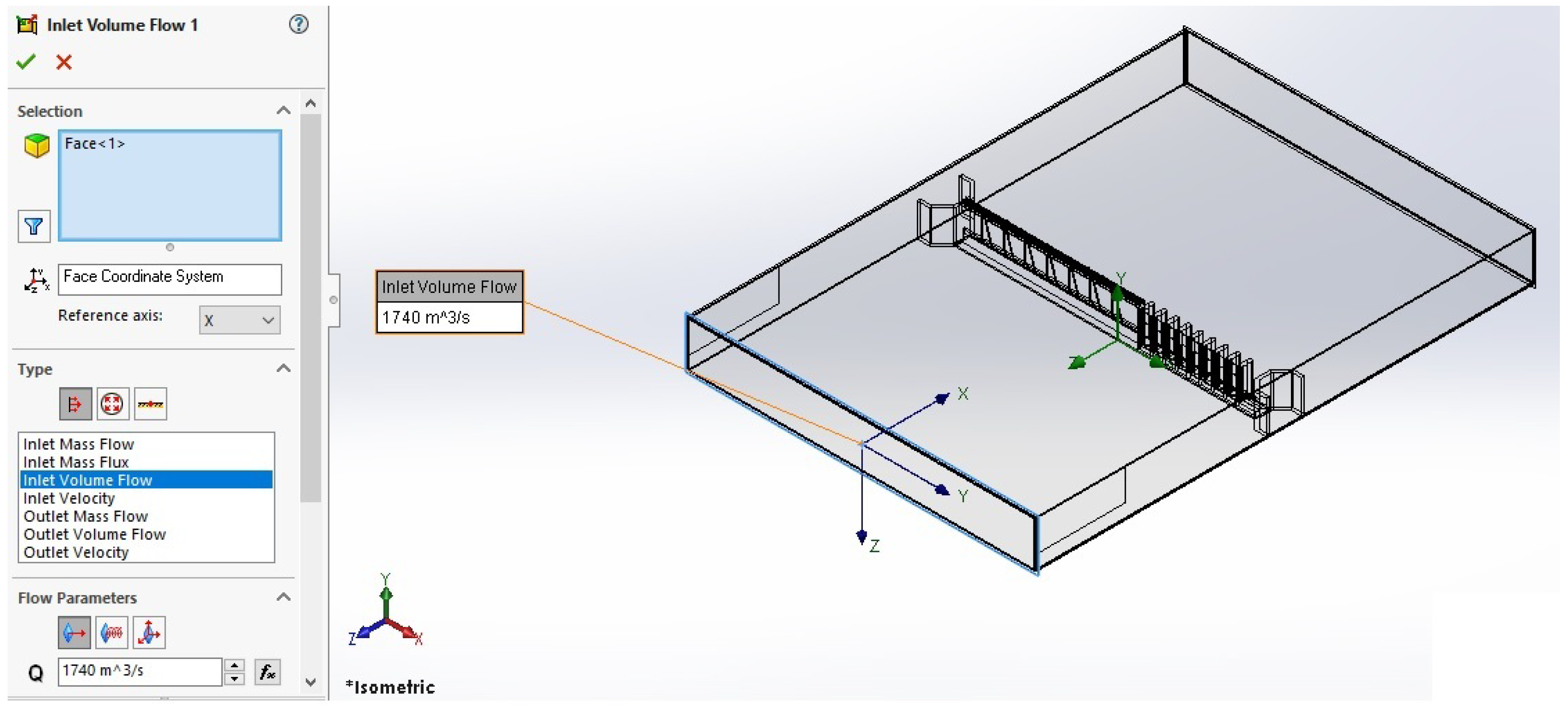
In the simulation, the interaction between the gate and water (Fluid–Structure Interaction) was important. Water flow entering and exiting the gate was defined, including details such as the speed and pressure. Environmental factors such as the water level and pressure changes were also included. The flow simulation add-in in SolidWorks 2020 was used to measure fluid flows through the model. The gate was designed according to relevant standards and codes. This method helps find the best gate for the hydraulic structure based on the current flow rate. The flow simulation focuses on fluid behavior within a fully enclosed space, as shown in
Figure 16.
The add-in for flow simulation uses at least one inlet and one outlet, which is exactly what was used for this simulation concept. The lids were designed to seal the hydraulic structure and channel to perform a simulation. With the basics of the extrusion feature with suitable parameters or boundary conditions, SolidWorks 2020 Flow Simulation was able to simulate the gated structure performance with various fluid properties.
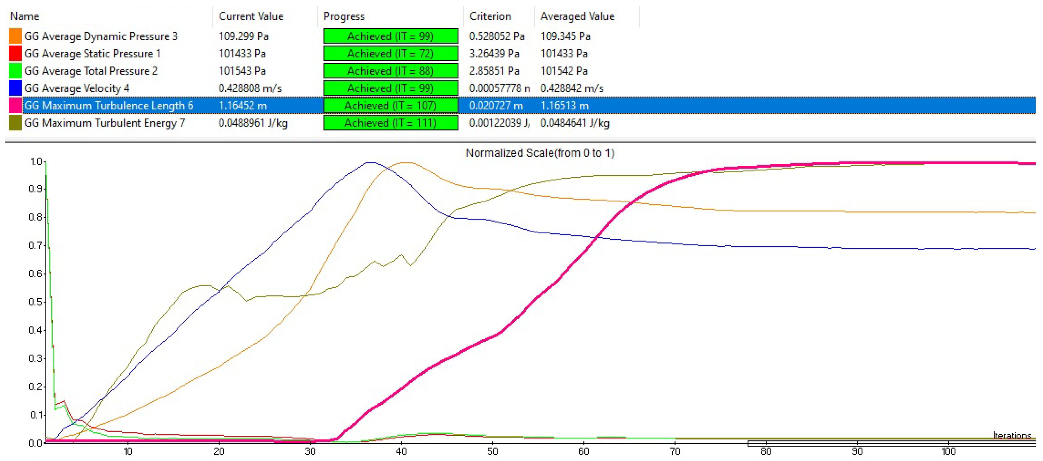
Figure 17a is the boundary conditions such as the inlet pressure, outlet pressure, and operating temperature along with the fluid velocity that need to be set to run the flow simulations, while
Figure 17b is the various results approaches that could be used to analyze the data. In
Figure 17c, it could be seen that the Solid Works 2020 Flow simulation provides various inlet substances from its directory, and it shows that a custom substance could be keyed in if the fluid properties are known.
SolidWorks 2020 Flow Simulation was used to model the water flow around the flap gate. Water properties such as the density, viscosity, and temperature were included, and a mesh was created to accurately capture the fluid behavior. The mesh was refined in critical areas, such as around the edges and hinges. A turbulence model (k-ε) was used to capture the complex flow behavior around the gate. The fluid simulation showed how water moved around the gate, highlighting areas of high pressure or turbulence that might cause problems as shown in
Figure 18.
Solid Works 2020 Flow Simulation module was utilized to conduct CFD analysis of fluid flow patterns around and through the gate system. This allows for the visualization and quantification of flow velocities, pressures, and turbulence, providing insights into the hydraulic performance of the gates. Sensitivity analysis within Solid Works Flow Simulation was performed to assess the impact of design variations and operating conditions on flow behavior. This helps identify critical factors influencing the effectiveness of the gate system and informs design optimization efforts. The flow simulation results were integrated with optimization algorithms to optimize the operation of the gate system in response to changing flood conditions. This could involve determining the optimal gate opening angles or scheduling gate operations to maximize flood control efficiency while minimizing adverse impacts downstream. By integrating design optimization, structural analysis, and flow simulation capabilities within Solid Works 2020, the proposed gate system for Halpan Ela Anicut can be optimized to enhance flood management in Anuradhapura City, Sri Lanka. This comprehensive approach ensures that the final design is not only structurally sound but also hydraulically efficient and responsive to dynamic flood conditions.
3. Result and Discussion
For the flow simulation of the above-created 3D model, we need to determine the river’s minimum and maximum flow rates [
35]. In the case of the Malwathu Oya River, it is an open-channel-type flow [
36], and we can calculate these flow rates using Equation (21) as follows [
31]:
This equation is used to determine the flow rate Q of a rectangular contracted weir, where
Q = flow rate in cfs, B = bottom width of the weir in feet, H = height of the upstream water above the weir crest in feet. Using the above equation and the collected data, we determined the minimum and maximum flow rates of the river to be 273 m
3/s and 1740 m
3/s, respectively. We then created a 3D model of the existing Sluice Gate system, as shown in
Figure 19, using SolidWorks software.
This model, based on detailed data from the Irrigation Department, incorporated the hydraulic structure of the gate. After modeling, we conducted a flow simulation for the Sluice Gate system, applying both the maximum and minimum flow rates to evaluate its performance under varying conditions. A key part of this analysis was examining the pressure difference on the upstream side as the gate opening varied.
After 3D modeling the existing gated structure, simulations were conducted using both the minimum and maximum flow rates.
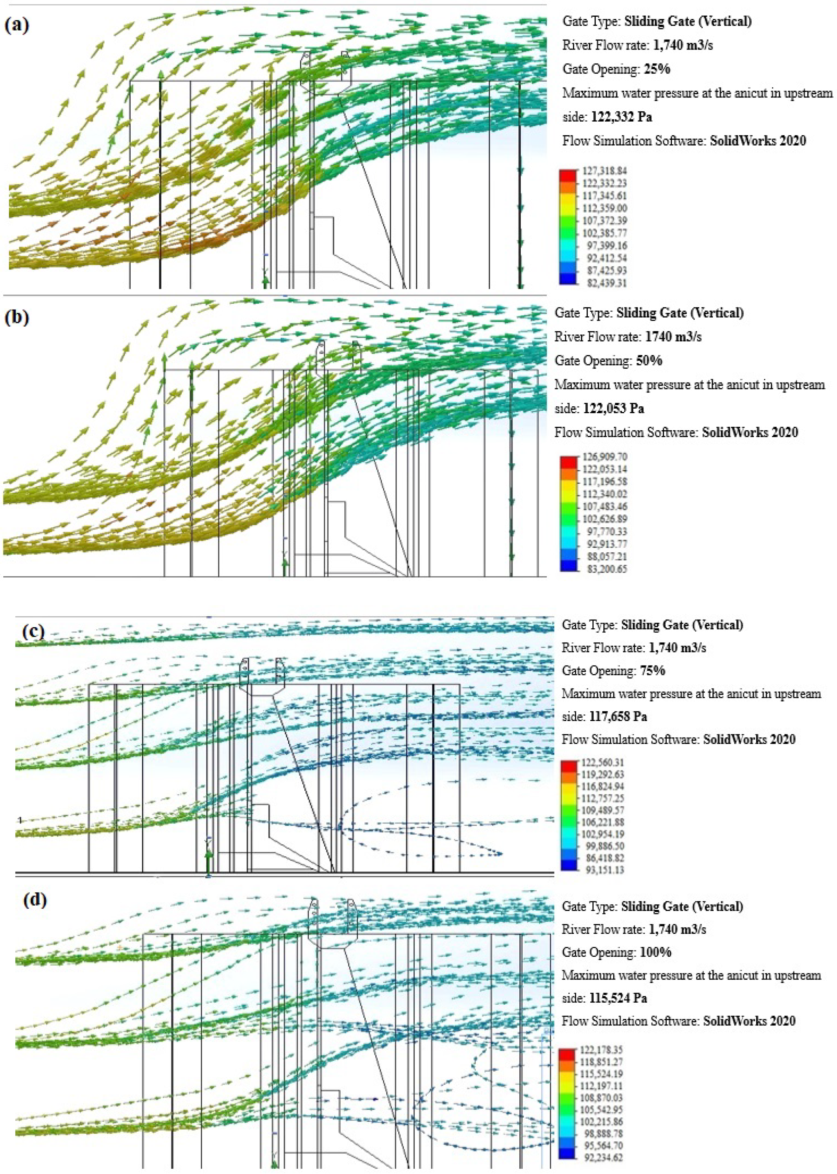
Figure 20a–d displays the results for the maximum flow rate of 1740 m
3/s with gate openings of 25%, 50%, 75%, and 100%, respectively. These results highlight several key points: the upstream pressure is highest at a 0.5 m gate opening, indicating restricted flow and increased water accumulation. As the gate opening increases to 2 m (100%), the upstream pressure decreases, allowing more water to flow through and reducing accumulation. The simulations also show that the upper catchment area of the river is inundated at gate openings of 25% (0.5 m) and 2 m under the maximum flow rate of 1740 m
3/s. This suggests that these gate positions are insufficient to prevent flooding in the upper catchment area, which has important implications for flood management and river infrastructure.
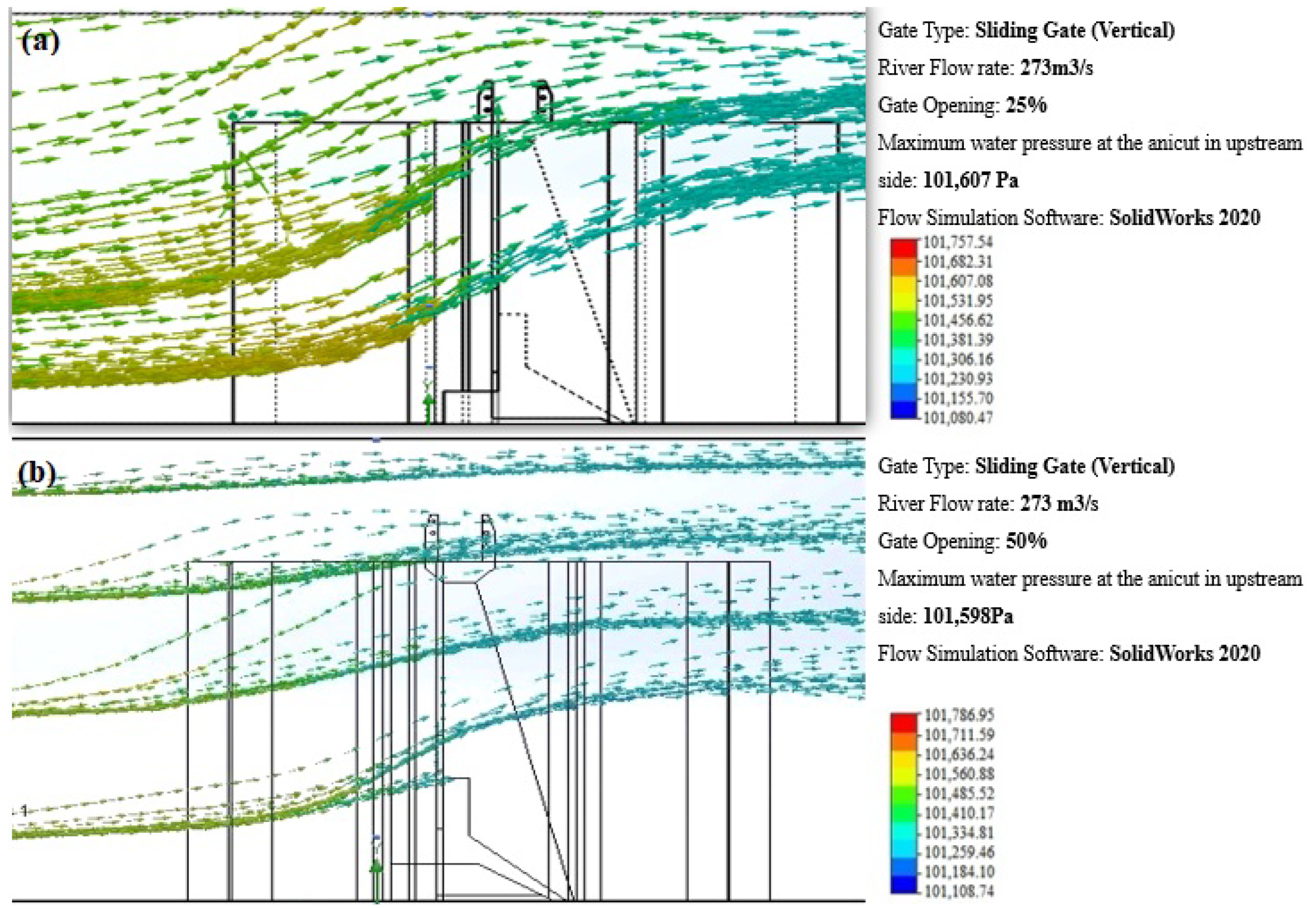
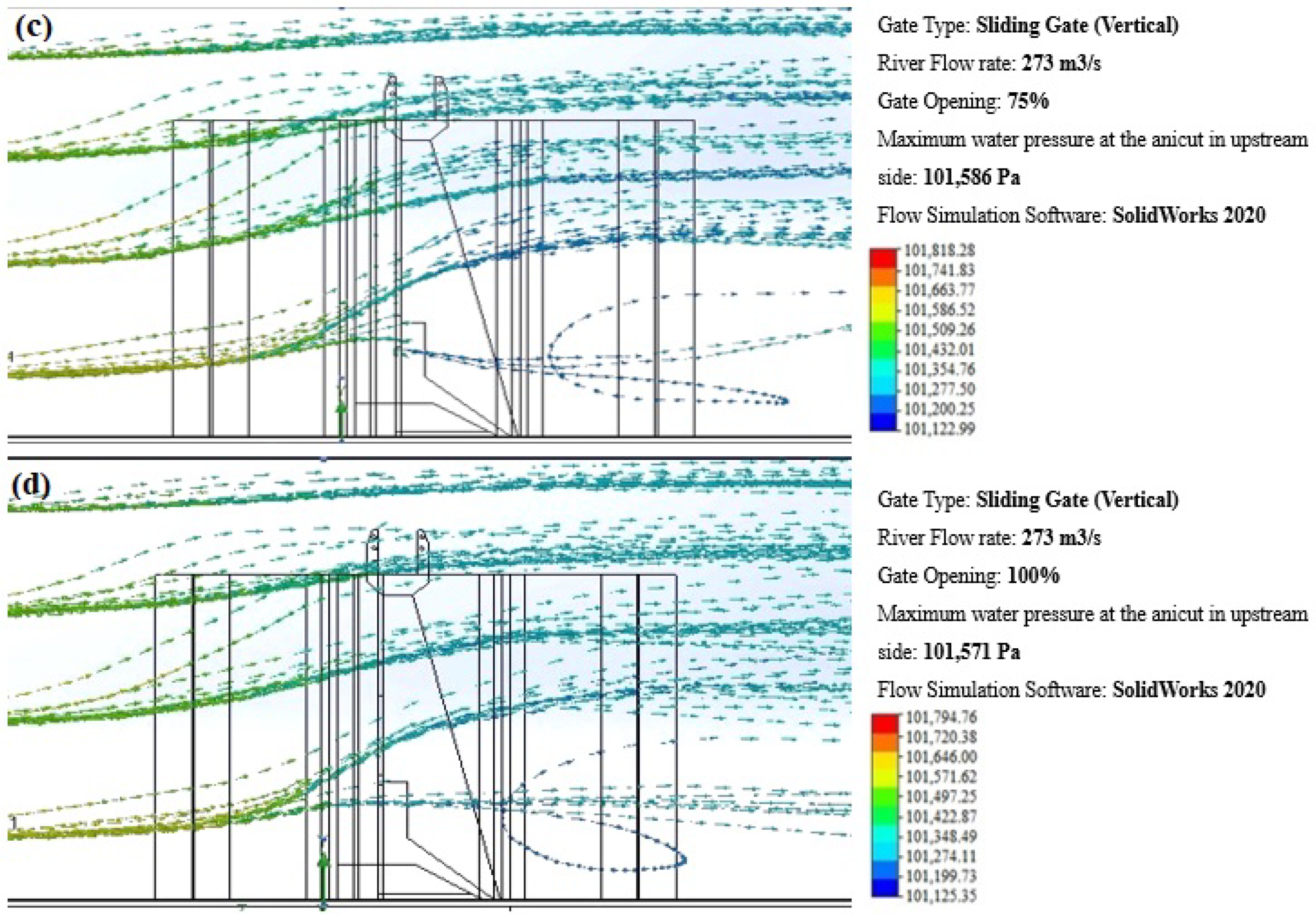
Simulations using the minimum flow rate of 225 m
3/s were also conducted.
Figure 21a–d presents the simulation results for gate openings of 25%, 50%, 75%, and 100%, respectively. Several key observations emerged from these results. First, the upstream pressure varies with different gate openings: at a 0.5 m (25%) gate opening, the upstream pressure is significantly higher, indicating restricted flow and increased water accumulation. As the gate opening increases to 2 m (100%), the upstream pressure decreases, allowing more water to flow through and reducing upstream accumulation. Second, the simulations show that the upper catchment area is inundated only at a 0.5 m (25%) gate opening under the minimum flow rate, indicating insufficient flow to prevent flooding. However, at gate openings of 2 m (100%), the water level in the upper catchment area does not increase, suggesting better flow management and reduced flood risk. These findings highlight the importance of adjusting gate openings to manage upstream pressure and prevent inundation. For the minimum flow rate, larger gate openings effectively manage the flow, preventing flooding in the upper catchment area. This has significant implications for flood management, suggesting that gate operations need to be carefully calibrated based on flow rates to ensure optimal performance and safety.
The flow simulation results in this study indicate that upstream water pressure varies with different gate opening configurations. When comparing various gate types such as non-rising spindle gates, fixed wheel gates, barrage gates, and caterpillar gates, all of these operate similarly to the spindle gate due to their vertical, upward opening mechanism, classifying them as underflow gates. Underflow gates have been shown to be less effective in efficiently releasing floodwater, as their vertical opening mechanism does not adequately reduce upstream water pressure [
37]. Consequently, the upstream water pressure remains relatively consistent across these gate types, including the spindle gate [
38].
In the case of radial gates, although they are also classified as underflow gates, their upward radial opening creates blockages and disturbances in the downstream flow, much like the spindle gate. This disruption contributes to their inefficiency in managing floodwater and in reducing upstream water pressure. Studies have shown that the design of radial gates can cause flow interruptions that exacerbate flood risks, particularly in high-pressure scenarios.
Valve-type gates, including butterfly and other axial designs, while useful for controlled, low-flow situations, are not well-suited for floodwater management. Their operational design, which often involves vertical or axial opening, does not offer significant advantages for handling high-flow floodwater. Research has shown that these gates lack the capacity for rapid discharge, making them inadequate for emergency flood control scenarios [
39].
In contrast, the flap gate operates as an upper-flow-type gate, opening downward in a radial direction. When fully opened, the flap gate allows smooth, unobstructed downstream flow with minimal disruptions or blockages, a characteristic that underflow gates lack [
40]. However, during the initial stages of gate opening, minor flow blockages may occur. As such, it is critical to perform flow simulations at various gate opening levels to assess the performance of the flap gate under different conditions [
41]. The following analysis presents the simulation results for flap gate performance across varying gate openings, offering a more comprehensive evaluation of its flood management capabilities.
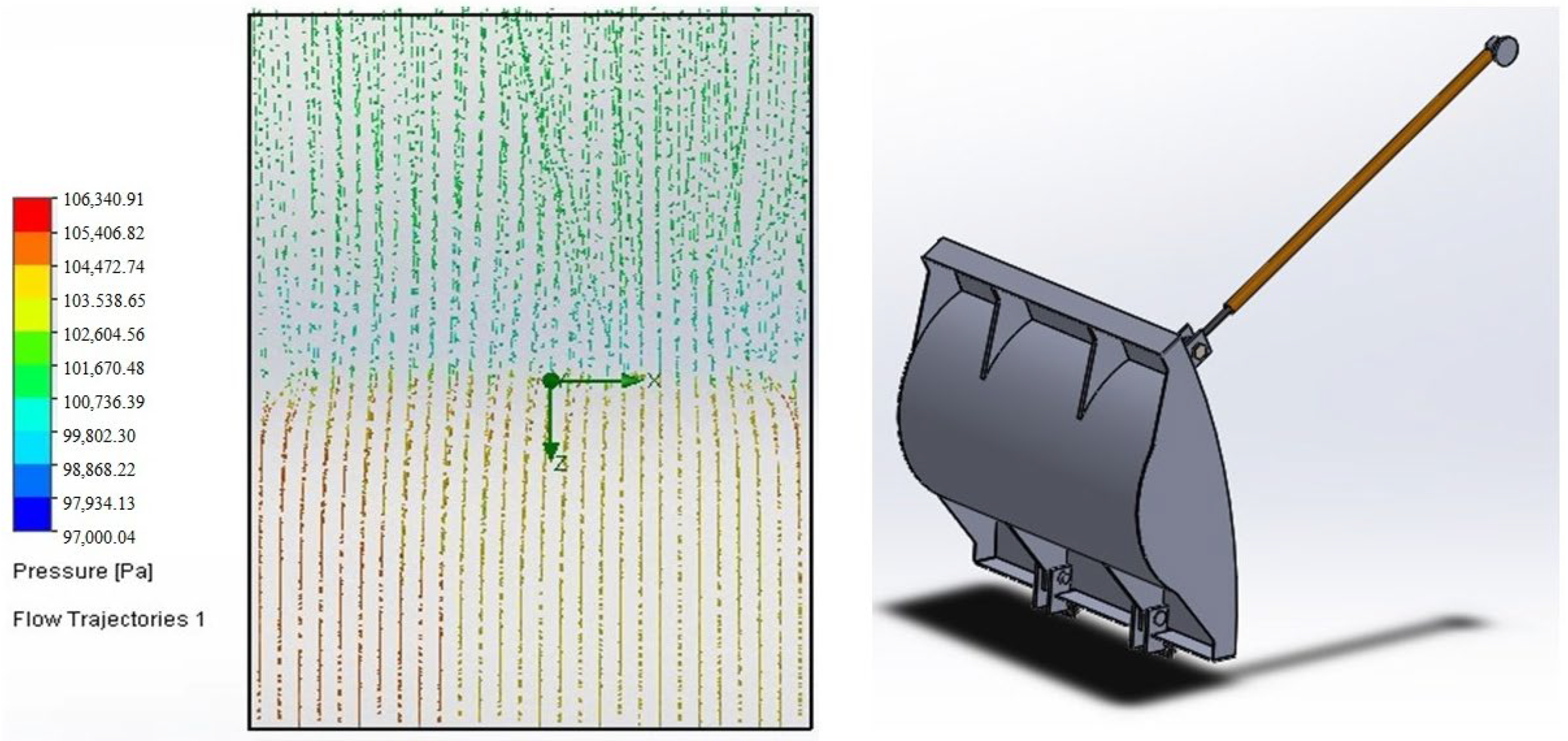
SolidWorks 2020 software was employed to develop a detailed 3D model of the flap gate system, utilizing data provided by the Irrigation Department, as illustrated in
Figure 22. The process involved creating an accurate and comprehensive model that facilitated subsequent flow simulations to assess the system’s performance under varying conditions [
42]. A flow simulation was conducted to evaluate the system’s behavior at both maximum and minimum flow rates, with a specific focus on the upstream pressure difference relative to the gate opening space from the bottom [
43,
44].
This simulation approach was designed to provide critical insights into the hydraulic performance and operational efficiency of the flap gate system. It enabled the identification of potential design flaws and areas for improvement by analyzing the gate’s interaction with different flow conditions [
45]. Such detailed simulations are essential for optimizing the design and functionality of hydraulic structures, ensuring they meet performance expectations and operational requirements in practical applications [
46]. The results obtained from this simulation are instrumental in refining the flap gate system, thereby enhancing its effectiveness and reliability in real-world scenarios.
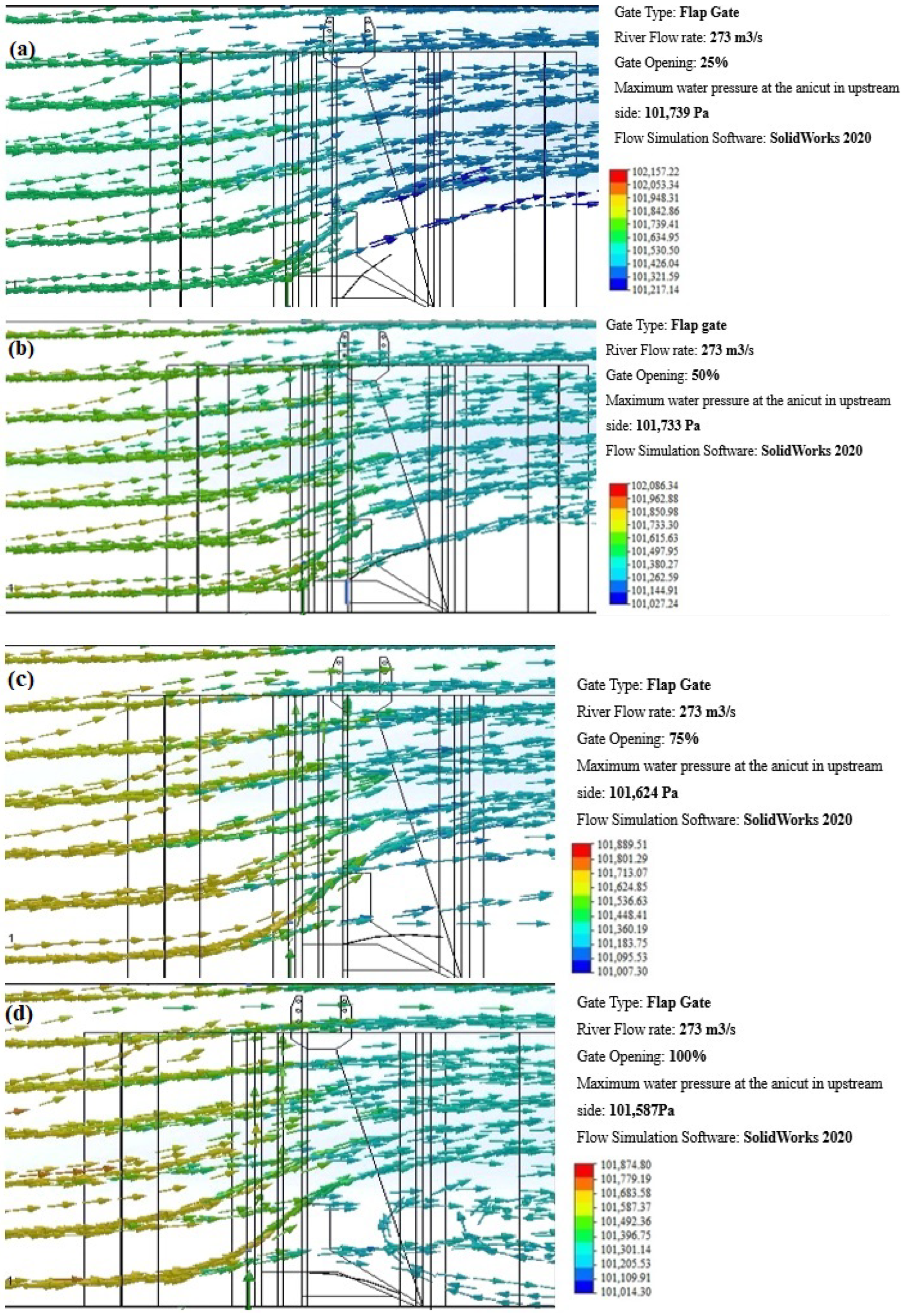
The newly designed flap gate system was simulated using both minimum and maximum flow rates of 225 m
3/s and 1740 m
3/s, respectively.
Figure 23a–d presents the simulation results for gate openings of 25%, 50%, 75%, and 100%. The simulations indicate effective management of upstream pressure for all gate openings. At a 0.5 m (25%) opening, the gate controls the flow adequately, maintaining stable upstream conditions. When fully opened at 2 m (100%), the gate efficiently handles the increased water volume, demonstrating the system’s capacity to manage varying flow rates without excessive pressure buildup. The results show that the upper catchment area is not inundated at any gate position or flow rate.
This is a significant improvement, indicating that the newly designed flap gate system can effectively prevent flooding in the upper catchment area, even under maximum flow conditions. The simulation results demonstrate that the newly designed flap gate system performs exceptionally well under both minimum and maximum flow conditions. It effectively manages upstream pressure, prevents the inundation of the upper catchment area, and maintains stable flow dynamics. These findings confirm the robustness and reliability of the new gate system, making it a valuable asset for effective water management and flood prevention.
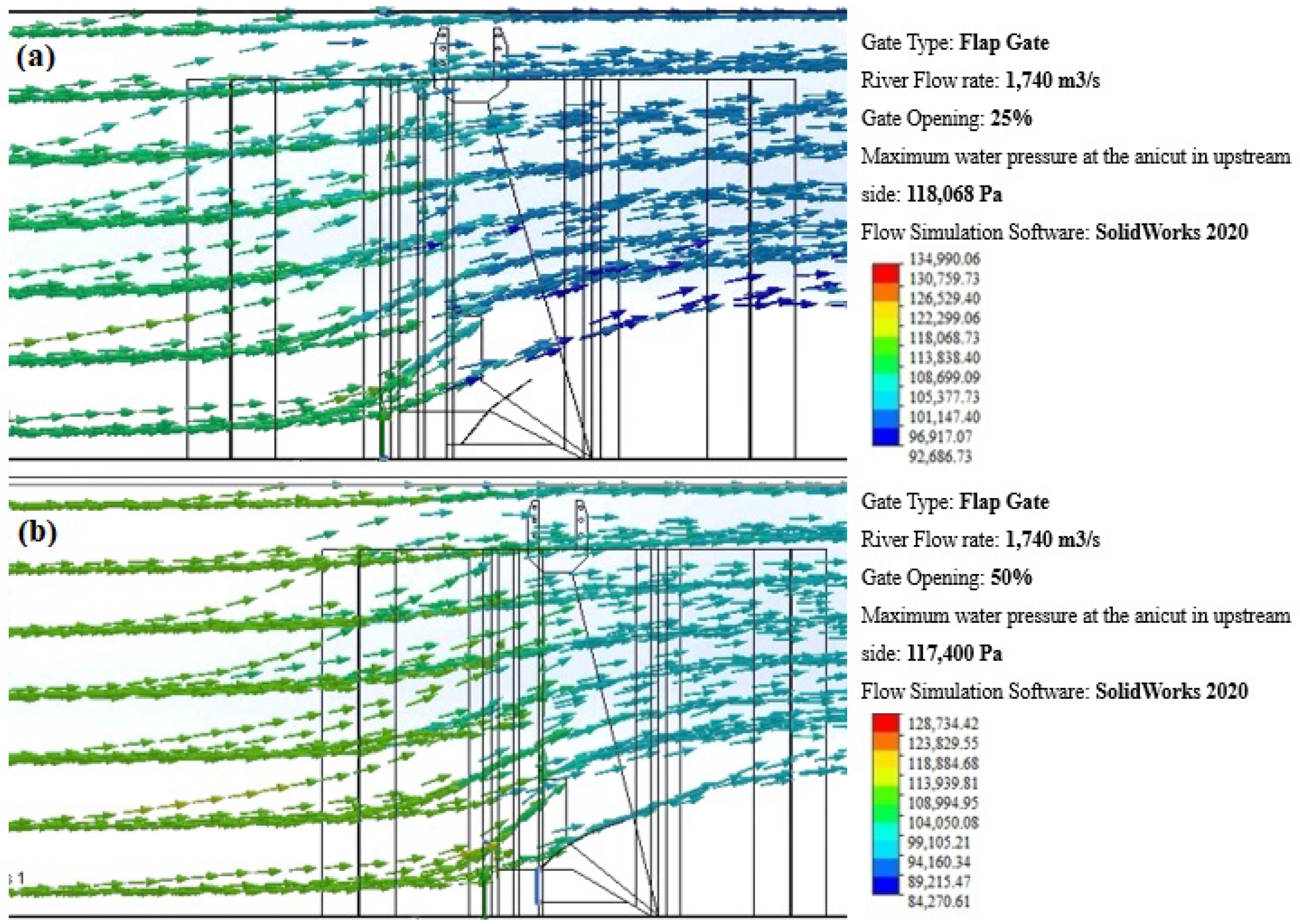
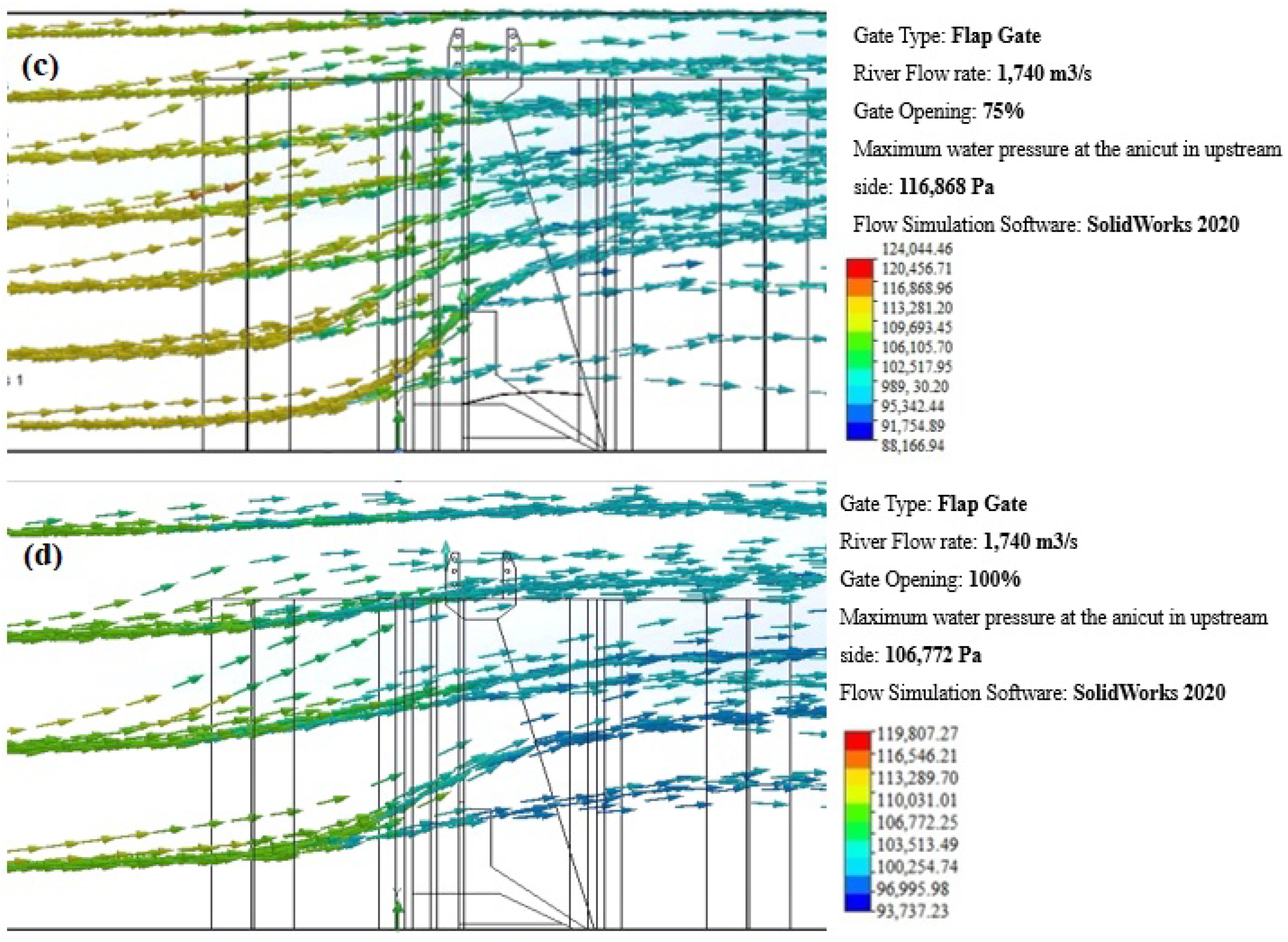
Simulations using the maximum flow rate of 1740 m
3/s were also conducted.
Figure 24a–d presents the simulation results for gate openings of 25%, 50%, 75%, and 100%, respectively. Several key observations emerged from these. First, the upstream pressure varies with different gate openings: at a 0.5 m (25%) gate opening, the upstream pressure is significantly higher, indicating restricted flow and increased water accumulation. As the gate opening increases to 2 m (100%), the upstream pressure decreases, allowing more water to flow through and reducing upstream accumulation. Second, the simulations show that the upper catchment area is inundated only at a 0.5 m (25%) gate opening under the maximum flow rate, indicating insufficient flow to prevent flooding. However, at gate openings of 2 m (100%), the water level in the upper catchment area does not increase, suggesting better flow management and reduced flood risk. These findings highlight the importance of the flap gate system in managing upstream pressure and preventing inundation.
The analysis of the flow simulation results reveals a distinct advantage of flap gates over vertical lifting sliding gates in terms of water pressure management. As illustrated in
Figure 24, the use of flap gates in the current anicut configuration results in lower upstream water pressure compared to vertical lifting sliding gates. This discrepancy in pressure is closely related to the height of the water level and the associated hydraulic dynamics [
47,
48]. Higher water pressure at the anicut generally indicates significant upstream inundation, which can exacerbate flooding conditions [
49].
Flap gates offer a notable improvement by reducing hydraulic barriers and enabling more efficient management of emergency flooding scenarios [
50]. The simulation results indicate that flap gates facilitate smoother water flow and better pressure regulation, addressing key issues associated with upstream inundation and pressure buildup [
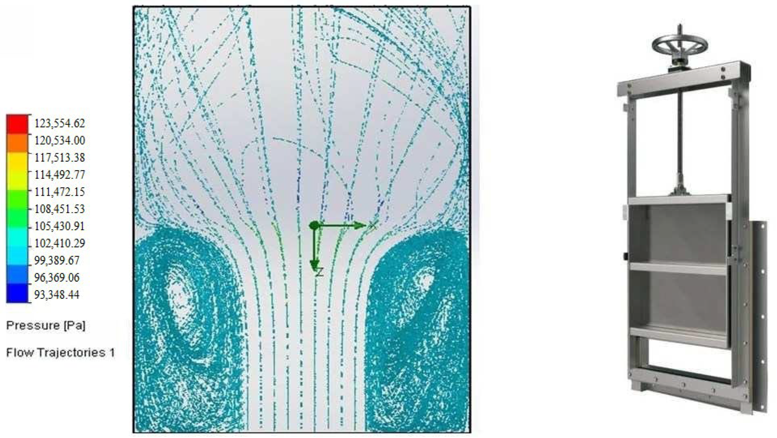
51]. The data presented in
Figure 25 demonstrate that the existing regulator gate system exhibits inefficient water distribution, characterized by turbulent flows and uneven pressure zones. This highlights the need for improvements to enhance flow management and overall system efficiency [
52].
The comparative analysis underscores that flap gates are more effective in mitigating upstream pressure and improving hydraulic performance in this specific anicut setup. By minimizing flow obstructions and optimizing the pressure distribution, flap gates provide a more robust solution for managing high-flow conditions and reducing the risk of flooding [
53]. These findings support the recommendation to adopt flap gates for more effective flood management and enhanced operational efficiency in the given context.
Figure 26 illustrates the water flow patterns observed after the installation of the flap gate. The simulation highlights the changes in water dynamics, showing how the flap gate effectively manages water flow, reducing turbulence and ensuring a more controlled and efficient distribution. Key areas of interest include the altered velocity profiles and pressure distributions, which demonstrate the improved performance and functionality of the system post-installation [
54,
55].
