1. Introduction
Debris flow is a common mountain disaster, widely distributed around the world. The casualties and economic losses caused by debris flow every year are staggering [
1,
2]. In the United States, they cause in excess of USD 1 billion in damages and from about 25 to 50 deaths each year (USGS, 2023). Globally, landslides cause many billions in damages and thousands of deaths each year [
3,
4]. Some of the most vulnerable groups to debris flows are those who are economically restricted to living in relatively inexpensive and more dangerous locations, are often forced to live in topographically cramped areas due to expansion and development, and have limited influence and power needed to bring about mitigative efforts [
5]. However, debris flow disasters often have a greater impact on these people; so, it is very necessary to study the movement law of debris flow disasters in cities to provide a basis for debris flow warning and forecasting.
Debris flow is a complex multiphase flow, and its movement is significantly affected by flume slope, barrier height, particle size distribution, among other factors [
6,
7]. Most scholars concentrate on the movement of debris flow along a single channel [
8]. When debris flows move into a city, they often encounter complex terrains and road network, such as cross channels or branches that affect their movement and impact. These terrains can cause debris flows to diverge or mix at the cross channels, resulting in changes in their movement parameters, such as speed, pressure, and concentration. These changes can also influence the impact force and damage degree of debris flows on the downstream river bed and the control project [
9]. However, the mechanism and effect of debris flow shunting at cross channels are not well understood. Therefore, studying how debris flow splits at cross channels is very important and useful for understanding how debris flow moves, evaluating the danger of debris flow, and improving ways to prevent and reduce debris flow.
Debris flow behaves under different conditions, such as slope, terrain, particle size, and fluid viscosity [
10]. The movement law of debris flow is important for understanding the mechanism, impact, and risk of debris flow disasters, as well as for designing effective prevention and mitigation measures. However, the movement law of debris flow is complex and influenced by many factors, such as the interaction between solid and fluid phases, the resistance of the channel and the obstacles, and the effect of the cross channels and branches. Therefore, the movement law of debris flow is still an active research topic that requires further investigation. Various methods have been used to study the movement law of debris flow, such as laboratory experiments, field observations, numerical simulations, and theoretical models. These methods have provided some insights into the movement characteristics, parameters, and impact performance of debris flow under different scenarios. Many debris flow models were proposed, such as Savage–Hutter theory, [
11,
12,
13], a finite volume formulation model [
14], a thermo-pore-mechanical model [
15], and the velocity-dependent friction law [
16].
Cross channels are a type of branching structure that can be used to divert or mix two-phase flow in pipelines [
17]. The diverting effect of two-phase flow in cross channels refers to how the flow distribution and pressure drop of two-phase flow are affected by the geometry and configuration of the cross channels. The diverting effect of two-phase flow in cross channels is an important issue for the design and operation of pipeline transportation systems, especially for oil and gas pipelines [
18,
19,
20]. The diverting effect can influence the performance, safety, and efficiency of the pipeline systems. For example, it can affect the flow rate, pressure drop, heat transfer, phase separation, corrosion, erosion, and vibration of the pipelines [
21,
22,
23]. However, it receives little attention in debris flow. Several methods have been used to study the diverting effect of two-phase flow in cross channels, such as experimental investigations, numerical simulations, and theoretical models. These methods have provided some insights into the flow patterns, pressure drop, mass transfer, and phase separation of two-phase flow in cross channels under different conditions [
24]. However, there are still some challenges and limitations in these methods, such as the scale effect, the boundary condition, the parameter calibration, and the validation [
25,
26]. These studies offer some experimental evidence and practical insights for the shunt effect of debris flow at cross channels. However, they cannot fully capture the complex flow phenomenon of debris flow at cross channels because the media and environment in the laboratory and field are very different [
27].
Debris flow is a type of solid–liquid two-phase flow that can cause severe damage to life and property. The flow characteristics of debris flow, such as speed, pressure, and concentration, are influenced by the complex interactions between solid particles and liquid water, such as friction, collision, suspension, and settlement [
28,
29]. To study the diversion effect of debris flow at cross channels, which is a common branching structure in natural and engineering environments, a mathematical model based on the conservation of mass, momentum, and energy is needed. Based on the two-phase flow theory and the energy conservation theory, the equation of solid–liquid two-phase motion of debris flow is derived. On this basis, considering the physical properties of the debris flow, the geometry of the cross-channel and the boundary conditions, a mathematical model of the diversion effect of the cross-channel debris flow was established. In this paper, a numerical method for solving the solid–liquid two-phase equation of motion for debris flow is also introduced, and it is applied to typical engineering examples. The variation law of flow, flow velocity, pressure and other parameters of debris flow channel was analyzed, and the influencing factors and mechanisms are discussed. We compare and validate our results with existing experimental data or theoretical results. A series of numerical simulations are carried out by changing the physical properties of the debris flow, the geometry of the cross-channel and the boundary conditions. These simulations analyze changes in parameters such as flow, velocity, and pressure at the cross-channel of the debris flow. Finally, the factors and mechanisms influencing the diversion effect of debris flow are discussed.
2. Equation of Solid–Liquid Two-Phase Motion of Debris Flow
To model the flow diversion effect of debris flow in the cross channel, we consider the motion equation and interaction force of the solid–liquid phase of debris flow, and apply the conservation of mass, momentum and energy. We treat debris flow as a continuous medium of solid particles and liquid water, with friction, collision, suspension, settlement and other forces between the phases. In this paper, the Euler coordinate system is used to describe the debris flow motion, ignoring gravity, inertia and viscosity. The equation of motion of solid–liquid two-phase in debris flow is as follows:
Mass conservation equation in solid phase:
Mass conservation equation in liquid phase:
Momentum conservation equation in solid phase:
Momentum conservation equation in liquid phase:
Energy conservation equation in solid phase:
Energy conservation equation in liquid phase:
where
,
are the density of solid and liquid in debris flow, respectively.
,
are the velocity of solid and liquid.
,
are the pressure of solid and liquid.
is the specific internal energy.
is the force between solid and liquid.
represents the heat exchange between solid and liquid phase, which can be divided into four parts: friction, collision, suspension and settling forces.
where
is the convective heat transfer coefficient.
is the collision coefficient.
is the suspension coefficient.
is the settling coefficient.
is the number of colliding particles.
is the number of suspension particles.
is the number of settling particles.
is the mass of colliding particles.
is the mass of suspension particles.
is the mass of the settling particles.
is the velocity of the colliding particles.
is the gravity.
The heat exchange
between solid and liquid phases can be expressed by Newton’s law of cooling:
where
is the convective heat transfer coefficient;
is the contact area of solid–liquid two phases;
and
are the temperatures of the solid and liquid phases, respectively.
To simplify the problem, this paper assumes (1) the debris flow is isothermal and incompressible, and neglect the volume change between the phases. Then, , so . (2) The densities of liquid and solid are constant, so , . Then, the equation of solid–liquid two-phase motion of debris flow can be simplified as follows:
Mass conservation equation in solid phase:
Mass conservation equation in liquid phase:
Momentum conservation equation in solid phase:
Momentum conservation equation in liquid phase:
Energy conservation equation in solid phase:
Energy conservation equation in liquid phase:
This is a nonlinear system of partial differential equations, which requires initial and boundary conditions for solving. A numerical method that combines finite difference and finite volume methods is used to solve the debris flow two-phase motion equation.
3. Numerical Solution Method
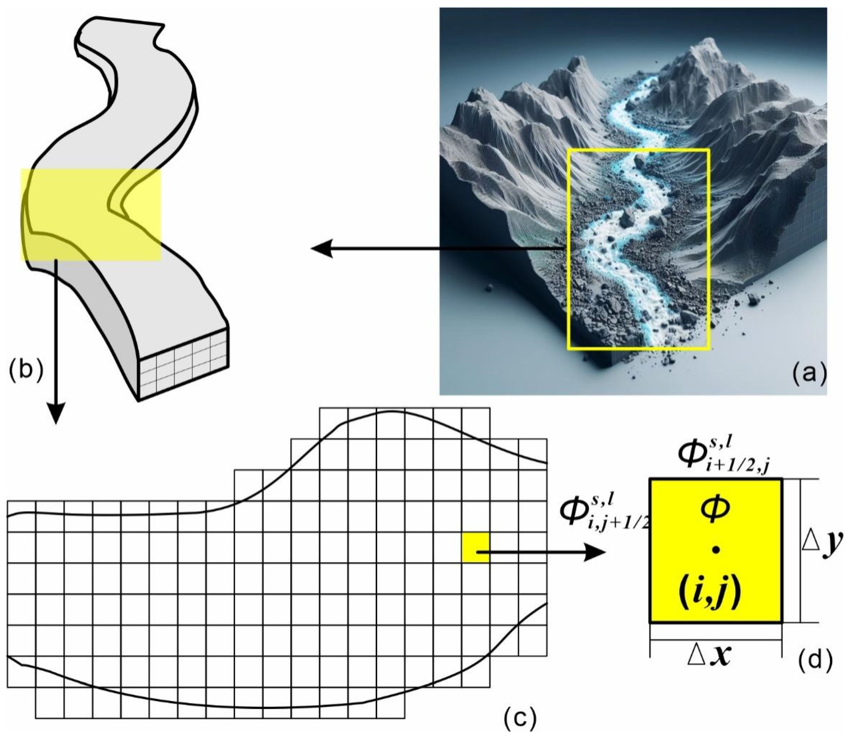
To solve the debris flow two-phase motion equation numerically, we discretize the equation and provide initial and boundary conditions. A hybrid method of finite difference and finite volume is used to split the debris flow trench into structured grids (
Figure 1). We represent the grid cell position, volume and face center by the coordinates of the cell center, the cell area and the boundary midpoint, respectively.
and are used to indicate the number of grid cells in the x and y directions, and superscripts and to indicate the solid and liquid phases. and are used to represent the lengths of grid cells in the x and y directions. We use to represent the time step. We use and to indicate any physical quantities in the at center (,) cell values.
We use the explicit finite difference method to discretize the mass conservation equation, and obtain the following:
In this paper, the implicit finite volume method is used to discretize the momentum conservation equation and obtain the following:
where
and
are the components of the force between solid and liquid phases in the x and y directions, respectively, and they can be calculated using the expression
.
The central difference method is used to discretize the convection term in the momentum conservation equation, and obtain the following:
The linear interpolation method is used to discretize the pressure term in the momentum conservation equation, and obtain the following:
We apply the iterative method to obtain the numerical solutions of velocity and pressure from the momentum conservation equation, subject to the convergence criteria. Then, we use the updated values of velocity and pressure to calculate the density from the mass conservation equation.
We assume the following initial and boundary conditions.
4. Numerical Simulation Results and Analysis
4.1. Diversion Effect of Debris Flow in Cross Channel
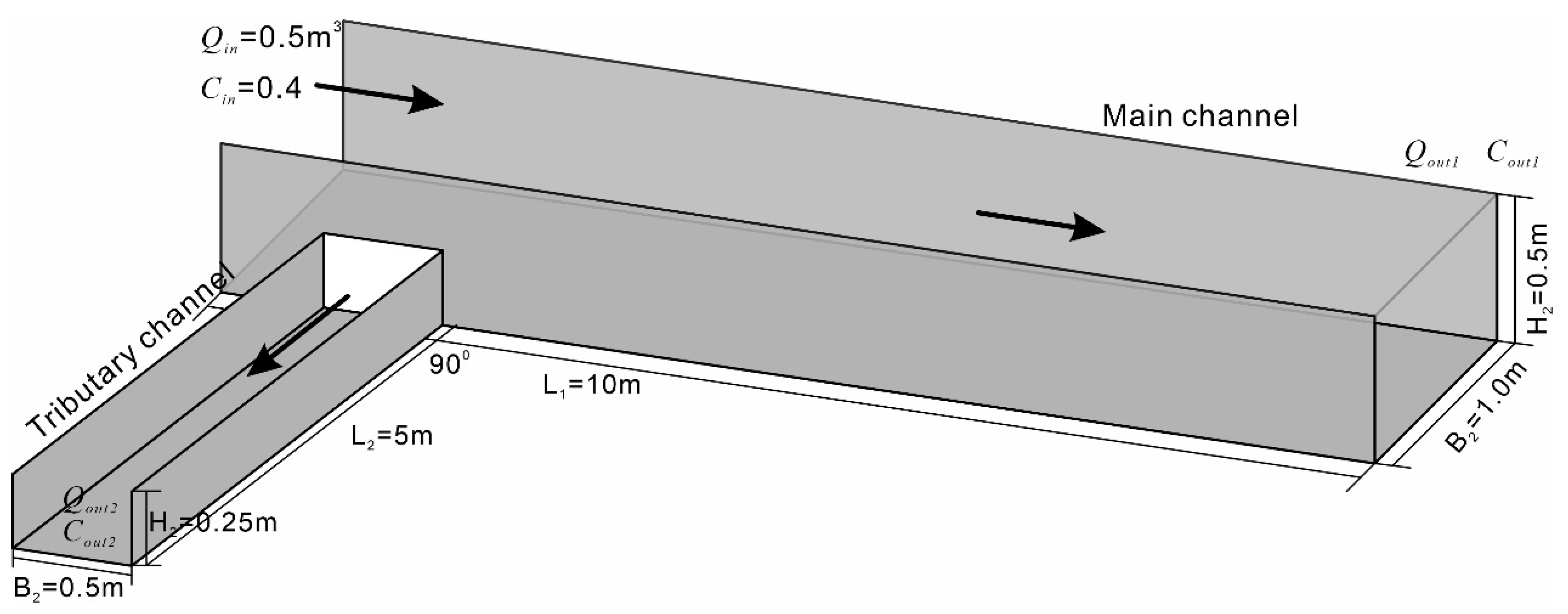
To validate the mathematical model and numerical solution method for the shunt effect of debris flow at cross channels, we conducted a numerical simulation based on a typical engineering case. The simulation results with the available experimental data or theoretical results were compared and analyzed. The engineering case involved a cross channel formed by two intersecting rectangular channels, as illustrated in
Figure 2. The parameters of the cross channel are as follows: The length of the main channel is
= 10 m, the width is
= 1 m, and the height is
= 0.5 m. The length of the tributary channel is
= 5 m, the width is
= 0.5 m, and the height is
= 0.25 m. The crossing angle is α = 90°. A debris flow inlet at the upstream end of the main channel has a flow of
= 0.5 m
3 and solid–liquid ratio of
= 0.4. There is a debris flow outlet at the downstream end of the main and tributary channels, respectively: its flow solid–liquid ratios are
,
and
,
, respectively. We assume that the density of debris flow is
=
= 1000 kg/m
3, friction coefficient is
= 1000 N·s/m
2. The collision coefficient is
= 1000 N·s/m, the suspension coefficient is
= 1000 N/m
3 and the settling coefficient is
= 1000 N/m
3.
The cross channel was divided into 200 × 100 × 50 grid cells, and the numerical solution method described above was used to solve the two-phase motion equation of debris flow. We took the time step
= 0.01 s based on the stability condition of the numerical scheme. We iterate to steady state using the following convergence criteria to determine whether the iteration converges:
where
represents any physical quantity such as speed, pressure, density, etc. n is the number of iteration steps.
is the allowable error, which is 10⁻⁶ in this paper.
We calculated the flow and the solid–liquid ratio of the debris flow at the exit of both channels. The results were as follows For the branch channel:
= 0.32 m3/s
= 0.38
For the main channel, and
= 0.18 m3/s
= 0.42
Therefore, we defined the diversion rate of the debris flow at the crossing channel as follows:
That is, 36% of debris flow is transferred to the branch channel, and 64% continues to flow along the main channel.
We compared the diversion rate obtained by numerical simulation with the existing experimental data or theoretical results, as shown in
Table 1. The table shows that the numerical simulation results are in good agreement with the experimental data or theoretical results. This indicates that the mathematical model and numerical solution method of the diversion effect of debris flow at the cross channel are correct and effective.
To explore the factors and mechanisms affecting the shunt effect of debris flow in the cross channel, we varied the physical properties of debris flow, the geometric shape of cross channel, and the boundary conditions. We then performed a series of numerical calculations to analyze how the flow rate, velocity, pressure and other parameters of debris flow changed in the cross channel.
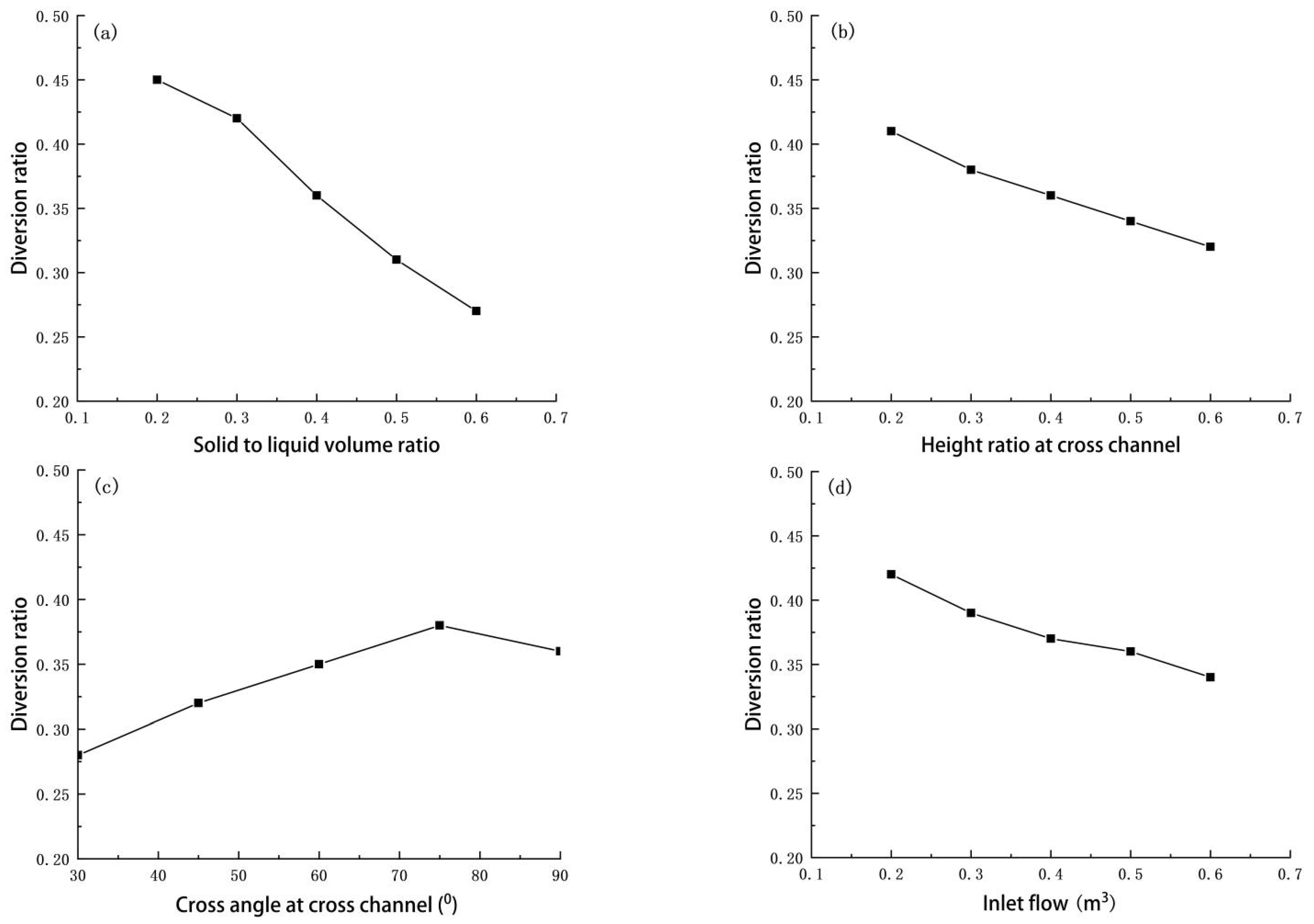
The shunt effect of debris flow in the cross channel depends on the solid–liquid ratio.
Figure 3a shows how the flow diversion rate of debris flow varies with the solid–liquid ratio at cross channels. A higher solid–liquid ratio increases the viscosity, friction, collision force, and sedimentation force of debris flow, but decreases the suspension force. This makes debris flow harder to turn at the cross channel and more likely to continue along the main channel, thus lowering the diversion rate. A lower solid–liquid ratio has the opposite effect. It makes debris flow easier to turn at the cross channel and enter the branch channel, thus increasing the diversion rate.
The shunt effect of debris flow in the cross channel depends on the height ratio of the branch channel to the main channel.
Figure 3b shows how the flow diversion rate of debris flow varies with the height ratio at cross channels. A higher height ratio means that the branch channel is higher than the main channel. This makes debris flow harder to turn at the cross channel and more likely to continue along the main channel, thus lowering the diversion rate. A lower height ratio means that the branch channel is lower than the main channel. This makes debris flow easier to turn at the cross channel and enter the branch channel, thus increasing the diversion rate.
The shunt effect of debris flow in the cross channel depends on the angle of the branch channel to the main channel.
Figure 3c shows how the flow diversion rate of debris flow changes with the angle at cross channels. A larger angle means that the branch channel is more perpendicular to the main channel. This makes debris flow easier to turn at the cross channel and enter the branch channel, thus increasing the diversion rate. A smaller angle means that the branch channel is more parallel to the main channel. This makes debris flow harder to turn at the cross channel and more likely to continue along the main channel, thus decreasing the diversion rate.
The diversion effect of debris flow in the cross channel depends on the inlet flow.
Figure 3d shows how the flow diversion rate of debris flow changes with the inlet flow at cross channels. A higher inlet flow means that the debris flow has greater inertia force and kinetic energy at the cross channel. This makes debris flow harder to turn and more likely to continue along the main channel, thus lowering the diversion rate. A lower inlet flow means that the debris flow has less inertia force and kinetic energy at the cross channel. This makes debris flow easier to turn and enter the branch channel, thus increasing the diversion rate.
The shunt effect of debris flow in the cross channel is influenced by many factors, but the solid–liquid ratio of debris flow and the geometry of cross channel are the most important ones. By modifying these factors, we can effectively control the diversion rate of debris flow and prevent its disaster. Moreover, we can use the generalized urban road network model and the debris flow movement model to calculate the flow and velocity of debris flow at different locations and times, which can provide data support for early warning and forecasting.
4.2. Diversion Effect of Debris Flow in Three-Way Cross Channels with Different Crossing Angle
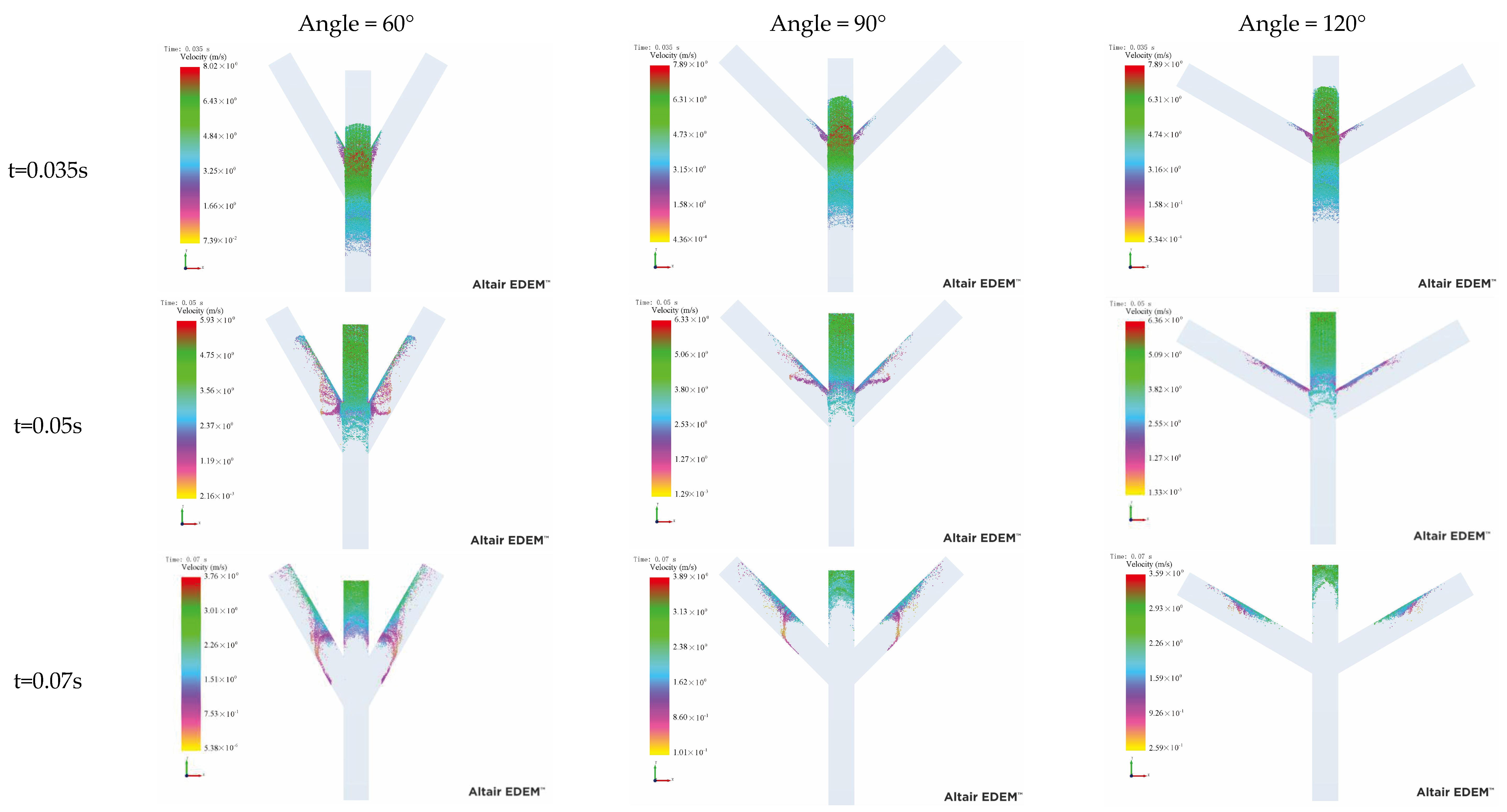
In order to consider the diversion effect of debris flow by three forks, a generalized model was established, in which the solid phase density was 2600 kg/m
3, the particle size was 0.6 mm, the fluid phase density was 1000 kg/m
3, and the viscosity coefficient was 0.001. The angles between the branches were 60°, 90° and 120°, respectively.
Figure 4 shows the movement process of debris flow in the three-way channels. When the debris flow moves to the cross channel, it is divided into three parts, but most of the debris flow still moves along the main channel because the velocity direction of debris flow is parallel to the main channel. Moreover, the velocity of the debris flows rapidly increases when it passes through the cross, but that within tributaries rapidly decrease. The debris flow within the tributaries exhibits turbulence, resulting in a rapid decrease in velocity. Notably, the greater the cross-angle, the more pronounced the turbulence phenomenon becomes, leading to an accelerated drop in velocity.
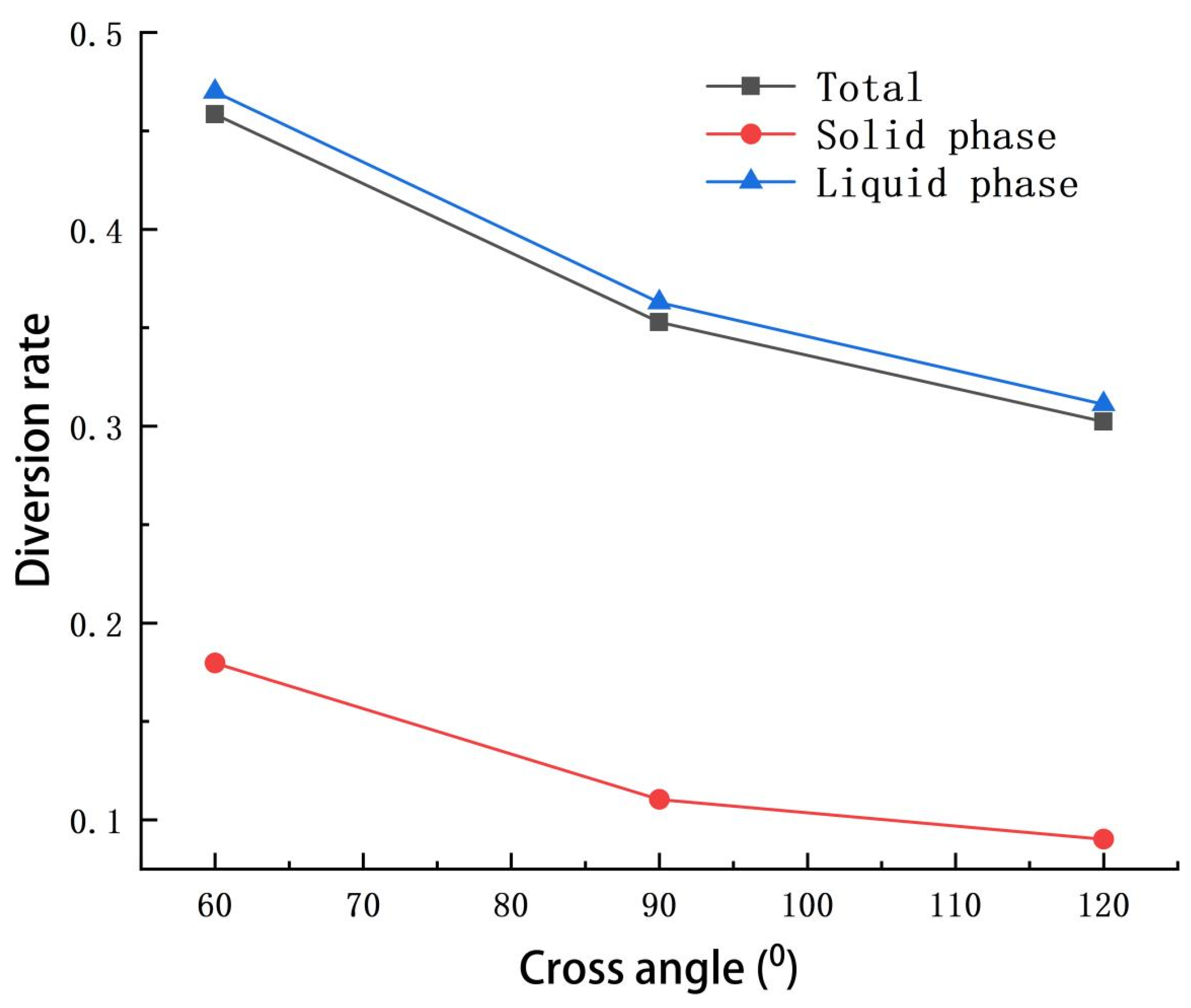
When the cross angle between tow tributaries was 60°, the diversion rate of the liquid phase was 0.47, but of the solid phase was 0.18. After the cross angle increased to 120°, the diversion rate of the liquid phase decreased to 0.31, and the solid phase reached 0.09 (
Figure 5). The diversion rate of total debris flow also decreased from 0.45 to 0.3 when the cross angle decreased to 120°. Thus, the diversion rate in the three-way channel decreased with the increase in cross angles. Moreover, the diversion rate of the liquid phase was obviously larger than that of the solid phase. Therefore, for the prevention and control of the main channel, more attention needs to be paid to the prevention and control of the solid phase, while for the prevention and control of the branch channel, the liquid phase needs to be targeted. It is worth noting that in the two-channel model, the larger the angle, the larger the diversion rate, but in the three-channel model, the larger the angle, the smaller the diversion rate. This is because in the two-channel model, the height and width of the main channel and the branch channel are different, while in the three-channel model, the width of the main channel and the branch channel are the same, assuming that the height is infinitely high, and the influence of the channel height on the debris flow movement is not considered. In addition, it can be seen from the results of the two-channel model that when the angle between the main channel and the branch channel is greater than 70°, the diversion rate begins to show a downward trend, which is consistent with the results obtained by the three-channel model, and the diversion rate decreases with the decrease in the angle between the main channel and the branch channel.
4.3. Limitations and Further Research
This paper presents a mathematical model and numerical method for studying the diversion effect of debris flow in cross channels. It offers a theoretical foundation and technical resources for the design of debris flow control engineering and disaster prediction. However, this study has certain limitations, such as neglecting the complex characteristics of debris flow, including its non-Newtonian, non-steady, and non-uniform nature, as well as the interaction between debris flow and the channel walls and bottom.
Future research should aim to enhance the solid–liquid two-phase motion equation of debris flow by incorporating more physical mechanisms and influencing factors. This would improve the accuracy and efficiency of the numerical method, thereby broadening its applicability and practical value. Additionally, by integrating it with the urban road network, we can calculate the migration process of debris flow in the city, which will then allow us to predict the disaster effects of urban debris flow. In addition, this paper lacks the comparison of experimental results with the results of other people’s papers, and lacks the necessary computing knowledge for corresponding calculations, which is difficult to compare with other methods.
5. Conclusions
This paper investigates the diversion effect of debris flow in cross channels and establishes a solid–liquid two-phase motion equation for debris flow. A numerical solution method, which combines the finite difference method and finite volume method, is employed to discretize and solve the equation. The validity and effectiveness of the mathematical model and numerical method are confirmed through a numerical simulation of a typical engineering case, and by comparing and analyzing with existing experimental data or theoretical results. The main conclusions are as follows:
Debris flow at the cross channel exhibits a diversion phenomenon. This means that a portion of the debris flow continues downstream along the main channel, while another portion diverts into the branch channel to flow downstream. The diversion rate, defined as the ratio of outlet flow to inlet flow of the branch channel, indicates the magnitude of the diversion effect.
The solid–liquid ratio and inflow significantly impact the diversion effect. A larger solid–liquid ratio makes it more challenging for debris flow to divert and more likely for it to continue flowing along the main channel, resulting in a smaller diversion rate. Conversely, a smaller solid–liquid ratio facilitates debris flow diversion, increasing the likelihood of it moving into the branch channel to flow downstream, thus leading to a higher diversion rate. A larger inflow makes it more difficult for debris flow to divert and more likely to continue flowing along the main channel, resulting in a smaller diversion rate.
The width ratio, height ratio, and angle of the cross channel also significantly influence the diversion effect. A larger width ratio makes it easier for debris flow to divert and increases its likelihood of flowing downstream into the branch channel, resulting in a higher diversion rate. A higher height ratio makes it more difficult for debris flow to divert and more likely to continue flowing along the main channel, resulting in a smaller diversion rate. A larger angle facilitates debris flow diversion and increases its likelihood of moving into the branch channel to flow downstream, thus leading to a higher diversion rate.
