Abstract
The high-resolution 3D groundwater flow and transport simulation problem requires massive discrete linear systems to be solved, leading to significant computational time and memory requirements. The domain decomposition method is a promising technique that facilitates the parallelization of problems with minimal communication overhead by dividing the computation domain into multiple subdomains. However, directly utilizing a domain decomposition scheme to solve massive linear systems becomes impractical due to the bottleneck in algebraic operations required to coordinate the results of subdomains. In this paper, we propose a two-level domain decomposition method, named dual-domain decomposition, to efficiently solve the massive discrete linear systems in high-resolution 3D groundwater simulations. The first level of domain decomposition partitions the linear system problem into independent linear sub-problems across multiple subdomains, enabling parallel solutions with significantly reduced complexity. The second level introduces a domain decomposition preconditioner to solve the linear system, known as the Schur system, used to coordinate results from subdomains across their boundaries. This additional level of decomposition parallelizes the preconditioning of the Schur system, addressing the bottleneck of the Schur system solution while improving its convergence rates. The dual-domain decomposition method facilitates the partition and distribution of the computation to be solved into independent finely grained computational subdomains, substantially reducing both computational and memory complexity. We demonstrate the scalability of our proposed method through its application to a high-resolution 3D simulation of chromium contaminant transport in groundwater. Our results indicate that our method outperforms both the vanilla domain decomposition method and the algebraic multigrid preconditioned method in terms of runtime, achieving up to 8.617× and 5.515× speedups, respectively, in solving massive problems with approximately 108 million degrees of freedom. Therefore, we recommend its effectiveness and reliability for high-resolution 3D simulations of groundwater flow and transport.
1. Introduction
Groundwater, as a vital natural resource, plays a crucial role in sustaining ecosystems and meeting human needs for drinking water, agriculture, and industry. For many years, the numeric modeling of groundwater flow and solute transport has been essential for gaining a deep understanding of complex groundwater systems and making informed decisions in groundwater resource protection [1,2,3,4,5,6,7,8]. Due to the three-dimensional (3D) spatial extent, high level of spatial variability, and high level of heterogeneity of groundwater systems, a groundwater simulation necessitates a large-scale, high-resolution numeric model over 3D space. This numeric model’s discretized solution leads to the solution of massive discretized linear systems that require a lot of computational time and space.
Scalable algorithms are necessary for efficiently solving massive groundwater flow and transport problems [9,10,11,12,13]. Generally, the Krylov space methods, such as the conjugated gradient (CG) and BiCGSTAB [14] methods, just to name a few, are used to solve the large linear system for groundwater flow and transport simulations [15,16]. However, as the linear system increases in scale, the convergence of these methods tends to decelerate [17]. To mitigate this issue with Krylov subspace methods, multigrid methods have been introduced to enhance solution efficiency, either as standalone solvers or as preconditioners in Krylov subspace methods. Multigrid methods [18] offer the advantage of convergence rates that are less dependent on the problem size, thereby enabling the number of iterations to be nearly constant. Hence, by using multigrid methods, the scalability of groundwater flow and transport simulations is greatly improved. Nevertheless, these multigrid methods tend to be algorithmically complex and are often tailored to specific problems, making them less robust compared with Krylov space methods.
Another effective approach to achieving algorithmic scalability in groundwater simulations is through parallelism. If the algorithm can be parallelized, the increased computational burden can be distributed across multiple processing units, resulting in runtimes that are less sensitive to the number of unknowns [19,20,21,22,23,24,25]. Parallelization computation has been developed in several hydrological software programs, such as tough2-MP V2.0 [26], PFLOTRAN V3.0.0 [27], RT3D V2.5 [28], PGREM3D V1.0 [29], and SWMS V1.00 [30], among others. To achieve parallelization for groundwater simulations, the multigrid method offers a solution for the parallelization of the linear system [31,32,33,34]. With the increasing computing power of graphics hardware, GPUs have demonstrated efficiency in the parallelization of groundwater simulations [24,35,36,37,38,39].
One of the most important techniques for parallelizing the computation associated with large linear system problems for groundwater simulations is the domain decomposition method, which was originally proposed by Herman Schwarz [40] and was used to solve elliptic partial differential equations [41]. Given a numeric problem associated with a large-scale spatial domain, the fundamental principle of the domain decomposition method is to employ a “divide and conquer” strategy that partitions the domain into multiple subdomains which are associated with a subsystem of the original numeric problem. Every subsystem is allowed to be solved independently and thus can be processed in parallel. The subsystems associated with subdomains are connected by their boundary nodes and constraints that combine the sublinear systems, which ensures that the solution of the subsystems is equivalent to that of the original problem. Because of the promising nature of the domain decomposition method, it has been exploited for the parallelization of groundwater simulations [42,43,44,45,46,47,48,49,50].
Developing an efficient domain decomposition approach for large-scale groundwater simulations is challenging. Directly applying a domain decomposition strategy for solving a large linear system proves impractical. Partitioning a large domain into a regular number of subdomains may result in a domain size that is prohibitively large for an efficient solution. However, an increased number of subdomains leads to exponentially increased computational overheads for algebraic operations that combine the results obtained from subdomains. Therefore, it is crucial to efficiently combine the solutions of subsystems to ensure the scalability of the domain decomposition algorithm.
In this paper, we present a novel two-level domain decomposition approach aimed at efficiently solving large-scale discrete linear systems for 3D groundwater flow and transport simulations. Our method leverages the principle of divide and conquer that is inherent in domain decomposition. We partition the large domain into appropriately sized subdomains to enhance the efficiency of solving linear systems within each subdomain. To integrate the solutions from each subdomain, we introduce an additional level of domain decomposition over the boundaries of the subdomains. This approach allows us to distribute the high computational burden of combining independent subdomains across multiple threads, thereby addressing the performance bottleneck inherent in the standard domain decomposition scheme. These speedup schemes constitute a novel dual-domain decomposition solver for large groundwater flow and transport problems, which permits the following:
- Finely grained subdomain sizes, enabling a low-cost and parallel solution for linear subsystems decoupled from the large domain;
- An efficient combination of subsystem solutions, enabling the seamless integration of subsystem solvers into a global solver for scalable groundwater simulations.
We demonstrate the efficacy of our proposed method through its application in a high-resolution 3D numerical model of chrome contaminant transport in groundwater. Our results highlight a significant performance boost for large-scale groundwater numerical systems with hundreds of millions of unknowns.
2. Methods
2.1. Governing Equations and Discrete Solution Methods
Groundwater flow through a porous medium, involving the movement of contaminant solutes, can be represented as the transient process of hydraulic heads. In this context, the groundwater flow can be represented by the continuity equation and Darcy’s law. Applying Darcy’s equation alongside the mass continuity equation, a comprehensive 3D model for groundwater flow across a confined aquifer, characterized by the hydraulic head , can be formulated as follows:
where is the tensor of hydraulic conductivity of porous medium in 3D space, respectively, is the rate of volume flow of unit volume fluid source/sink, and is the specific storage of the aquifer.
On the other hand, solute transport in transient groundwater flow can be modelled as the Fickian advection–dispersion model with retardation, first introduced by Taylor [51] and Bear [52] among others.
where is the solute concentration, is the time, is the retardation factor, is the porosity, is the dispersion coefficient tensor, is the Darcy velocity, is the rate of volume flow of unit volume fluid source/sink, and is the solute concentration of the fluid sink/source.
Given Equations (1) and (2), we can use the finite difference method or finite element method to spatially discretize them on a mesh [53]. This leads to a large linear system as follows:
where and are vectors of hydraulic heads and solute concentration. Matrix and , encoding the coefficients related to groundwater flow and transport, respectively, have the order of . For finite difference over a uniform mesh, for instance, is , where , , and are the number of finite definite grids in , , and dimensions, respectively. In high-resolution 3D groundwater transport simulations, wherein the detailed representation of both the simulated site’s size and spatial heterogeneities is crucial, the order can be several million, reaching up to in our specific case study. Therefore, the solution of the massive linear system in Equation (3) can be highly computationally expensive and even prohibitive.
In this regard, we devise a domain decomposition method to parallelize the solution of groundwater flow and solute transport equations. Domain decomposition offers an effective approach for parallelism, facilitating accelerated computation while maintaining solution accuracy.
2.2. Domain Decomposition Framework: Substructuring of Groundwater Flow and Transport Systems
In this section, we present our domain decomposition framework that substructures the discrete linear systems for groundwater flow and transport. Our domain decomposition is grounded in the principles of the Schur complement method [54], which is integral to certain domain decomposition approaches, especially for the computational domain, and is divided into non-overlapping subdomains. In domain decomposition, the coupling between subdomains occurs at the interface boundaries. The Schur complement method is used to form a reduced system (Schur complement system) that only involves the degrees of freedom at the subdomain boundaries. This reduced system over subdomain boundaries connects the solutions of each subdomain, ensuring that the combined solutions of all subdomains are equal to the solution of the original problem over the entire computational domain. Due to its effectiveness and efficiency, the Schur complement method has been widely applied to solve numerical problems within the domain decomposition framework [55,56,57,58]. In the following, we derive the domain decomposition framework based on the Schur complement method.
Given a large matrix in Equation (3) due to massive nodes within the mesh, we first partition the nodes into several regular subdomains. As illustrated in Figure 1, nodes in the mesh are categorized based on their spatial relation to subdomains, specifically into interior nodes and boundary nodes. Interior nodes are located inside a subdomain and do not directly connect to nodes in other subdomains, while boundary nodes reside on the interface between subdomains. Herein, boundary nodes can further be categorized into face nodes and edge nodes. The face nodes are located at the interface between two adjacent subdomains, while the edge nodes, as the remaining boundary nodes, are located at the interfaces connected to more than two subdomains.
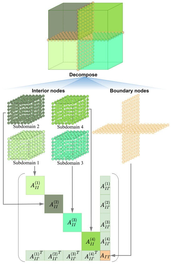
Figure 1.
An example of domain decomposition.
Based on this categorization, we reorder the matrix to generate block-wise substructures. By reordering the matrix , we let interior columns of interior nodes be prioritized in the ordered matrix, followed by those of boundary nodes. Therefore, the linear system in Equation (3) can be reformulated as follows:
where and are the blocks associated with only interior nodes and boundary nodes, respectively, is the block of coefficients connecting interior and boundary nodes, and are the variables of interior and boundary nodes, respectively, and and are the associated blocks on the right-hand side for these two categories of nodes. By further rearranging the columns of interior nodes based on their respective subdomains, the blocks in Equation (4) can be further refined and formulated as follows:
where the superscript indicates the block is associated with -th subdomain. Figure 1 illustrates an instance of for four subdomains. It is noted that each subdomain is linked to a diagonal block, labeled as . Additionally, each boundary corresponds to a boundary block, labeled as . Solution of interior nodes in Equation (5) yields the following:
Equation (6) indicates the variables for each subdomain can be solved independently, without knowing the values of degrees of freedom within other subdomains. Especially, since the order of is substantially reduced compared with that of , the solution of Equation (6) has much less complexity compared with that of Equation (3). For example, in a sparse solver with () time complexity for -ordered linear system, the overall time complexity for the solution of sublinear systems over subdomains is , where is the order of -th sublinear systems, satisfying . Thus, the overall complexity of these sublinear systems is much smaller than that of the original problem.
Inserting Equation (6) into Equation (5), we can derive a linear system, referred to as the Schur complement system or Schur system for brevity, as follows:
where
Equations (7) and (8) are related to the boundary nodes, representing the connection between subdomains. Thus, even though the solutions of the sublinear systems are independent of each other, the Schur system can “merge” the subdomains as a whole. This ensures that the independent solutions of the subsystems in Equation (6) collectively solve the original system in Equation (3).
While this domain decomposition technique significantly reduces complexity and enables parallelism by dividing the original problem into sub-problems across subdomains, it requires high computational overhead associated with the Schur complement system in Equation (7). Firstly, direct estimation of in Equation (8) involves a series of calculations of . This issue could be avoided by using the Krylov space method, such as CG or BiCGSTAB algorithm, which estimates the form, like in the algorithm, thus avoiding the explicit computation of . Secondly, the size of the Schur complement system depends on the number of boundary nodes. Thus, there exists a trade-off between partition granularity and solution complexity for Equation (7). Although a finely grained partition achieves low level of computation complexity over subdomains, a large linear system would be derived for increased boundary nodes between these subdomains. In the discrete solution of the solute transport equation, the preconditioned BiCGSTAB solver calls the preconditioner three times (see Appendix A). Especially in high-resolution 3D simulations, the approximated complexity for the solution of Equation (7) might result in unacceptable computational overhead.
2.3. Domain Decomposition Preconditioner: Another Level of Substructuring
To address the efficiency issue for Schur system solution, we observe that while the boundary nodes are massive, their subset, face nodes, and edge nodes are well organized in terms of their geometry and topology, with edge nodes forming the boundary of face nodes. Hence, we could explore an additional level of domain decomposition scheme for solving groundwater flow and solute transport systems. This approach creates a domain decomposition preconditioner in the CG and BiCGSTAB algorithms.
To derive the domain decomposition preconditioner for Equation (7), in which the boundary nodes are partitioned into substructures consisting of individual faces and edges, Equation (5) is rewritten to indicate the relation between each level of substructures as follows:
where and its transpose, , correspond to coefficients connecting -th face and -th subdomain, and denotes block associated with the face nodes over -th face. Figure 2 illustrates Equation (9) using the example from Figure 1, generated by substructuring the boundary nodes into face nodes and edge nodes.
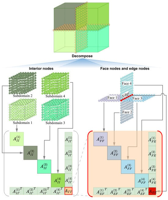
Figure 2.
A dual-domain decomposition scheme for the example illustrated in Figure 1.
With this formulation, the Schur system in Equation (7) can be formulated as follows:
where
Note that are non-zero blocks only when -th face is on the boundary of -th subdomain. and can be reformulated as follows:
where and are the indices of two subdomains adjacent to -th face.
Given the formulation in Equation (9), at first glance, we can use a preconditioner such as a block Jacobi preconditioner for solving the system.
In this preconditioner, however, each face between two subdomains requires the calculation of twice for estimation of or the solution of the Neumann–Neumann preconditioner [59] twice for the approximation of as shown below:
For either of the above schemes, the complexity is dependent on the size of subdomains, with a complexity of at least , where and are the numbers of interior nodes and face nodes, respectively. For faces within the boundary, the overall computation would be highly expensive.
Observing the form of in Equation (11), we ignore the term involving the calculation of the inverse in preconditioning Equation (10). Moreover, we observe that the subdomain is box-shaped. When employing a seven-point stencil in the finite element discretization of Equations (1) and (2), we obtain , [60]. This means , . In summary, our preconditioner for Equation (10) is as follows:
Given the upper-left diagonal block in Equation (15), we employ its special pattern for the solution of the preconditioner, which solves with respect to each face in parallel:
After eliminating , Schur system for Equation (15) is obtained as follows:
where
It is worth noting that the order of the linear system in Equation (18) is the number of edge nodes, with only a small proportion of boundary nodes. Therefore, the complexity for solving Equation (17) is significantly lower than that of Equation (7). It can be solved directly using preconditioned CG or BiCGSTAB. To avoid the estimation of the inverse , is used as a preconditioner for Equation (17), following the approach in Equation (15).
By combining Equations (16)–(18), we establish domain decomposition conditioner for Equation (7). This preconditioner avoids the expensive computation in block Jacobi preconditioner, such as the times estimation of or times solution of Neumann–Neumann preconditioner, as in Equation (13), in which the complexity is for each face. By fully exploiting the disconnected topology of faces over the boundary, the preconditioner can parallelize the solution of sublinear systems associated with faces, with the complexity of for each face. Thereby, the preconditioner reduces complexity substantially, improving the efficiency of the solution of the Schur system as in Equation (7). We will demonstrate in our case study that, due to the speedup in solution of Equation (7), we do not need to be too sensitive to the size of boundary nodes, thereby allowing for finely grained domain decomposition for low levels of complexity and efficiency in the groundwater simulation.
2.4. Solution of Subdomain Linear Systems
When the above domain decomposition method is applied to groundwater simulation, the linear system in Equation (3) will be solved multiple times in the numeric modeling process. In a solution of the linear system, the sublinear system with respect to , , and in each subdomain will be invoked many times. In particular, the order of is generally large. Thus, the selection of an appropriate linear solver for these linear systems is essential for the efficiency of the proposed method.
It is observed that the linear system (Equation (3a)) discretized from the groundwater flow equation is fixed in the time step of numeric modeling if the model parameters, such as hydraulic conductivity and specific storage, are independent of time. In such a case, we can precompute the Cholesky or LU factorizations for these linear systems before the iterations of numeric modeling. The Cholesky f and LU factorizations have time and space complexities of and , respectively, where is the number of interior nodes for a subdomain. In the solution of these linear systems, the precomputed matrix decomposition can be reused, and only back-substitute with the time complexity of is needed, thereby enhancing the performance of the domain decomposition method. This positive attribute is due to the fact that the dual-domain decomposition method allows for smaller subdomain sizes, thereby reducing the time and memory complexity of matrix factorization.
The linear system (Equation (3b)) derived from solute transport equations undergoes changes during iterations due to variable groundwater flow. In this scenario, we propose using preconditioned BiCGSTAB to solve these linear systems within each subdomain. Preconditioners such as incomplete LU decomposition can be utilized. It is noteworthy that BiCGSTAB invokes the preconditioner three times (see Algorithm A1 in Appendix A). Thus, the efficiency of solving the preconditioning system is crucial for optimizing the performance of the Schur system solution. The precomputation of incomplete LU decomposition is performed in the initialization of each iteration step. Although the linear the linear system is different in each iteration, the structures of their nonzero entries can remain fixed if parameters such as dispersion coefficient tensor, porosity, and retardation factor in the solute transport equation are time-independent. Therefore, in computing the incomplete LU decomposition, we optimize efficiency by reusing fill-reducing reordering and symbolic factorization, updating only values of the factorization.
2.5. Algorithm and Implementation
According to Section 2.2, Section 2.3 and Section 2.4, the workflow for the dual-domain decomposition can be summarized. For a time-sequential simulation, initially, the mesh is discretized into non-overlapping subdomains , generating matrix blocks corresponding with the interior, boundary, faces, and edges of subdomains. The matrix factorization for blocks associated with subdomains is precomputed. The dual-domain decomposition algorithm, outlined in Algorithm 1, receives blocks and their matrix factorizations, and solves the linear system discretized from groundwater flow and solute transport equations (Equation (3)) using two levels of domain decomposition. In the first level of domain decomposition, the subsystems for each subdomain are solved in parallel through efficient back-substitution based on the precomputed matrix factorization. The CG or BiCGSTAB method (see BiCGSTAB version in Appendix A) is utilized to solve the Schur system resulting from the domain decomposition. In particular, another domain decomposition preconditioner, which is summarized in the pseudo-code in Algorithm 2, is used for preconditioning the Schur system. Figure 3 illustrates a schematic diagram of the dual-domain decomposition process for the solution of Equation (3).
| Algorithm 1. Dual-domain decomposition for the solution of linear system discretized from groundwater flow and solute transport equations |
| Input: Sets of blocks , , , , , , , , , and ; Sets of matrix factorization for blocks of interior and face nodes , , and . Ouput: // Equation (8b) parallel for do ← LinearSolver() ← end parallel for ← // Equation (7) Preconditioner ← DomainDecompositionPreconditioner PrecondParam ← ,,,, ← SchurSystemSolver(,,, , , Preconditioner, PrecondParam) // Equation (6) parallel for do ← ← LinearSolver() end parallel for ← Reorder() |
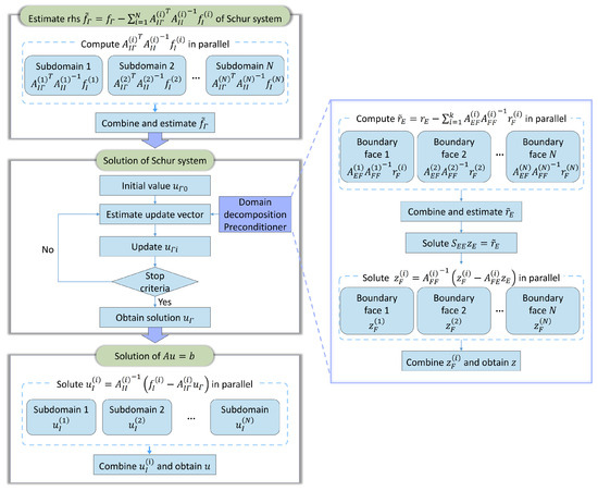
Figure 3.
Workflow of dual-domain decomposition process.
| Algorithm 2. Domain decomposition preconditioner |
| function DomainDecompositionPreconditioner (PrecondParam ← ,, }, ,}) // Equation (18b) parallel for do ← LinearSolver() ← end parallel for ← // Equation (17) Preconditioner ← IncompleteCGPreconditioner PrecondParam ← ← SchurSystemSolver(, ,, , , Preconditioner) // Equation (16) parallel for do ← ← LinearSolver( ) end parallel for return ← Reorder() end |
The proposed algorithm parallelizes major computations over multiple threads across subdomains and boundary faces. There are a total of four parallel blocks in the algorithm. Each thread corresponds to independent computations over subdomains and boundary faces, with no communication between threads, thereby requiring only one synchronization point when the parallel branches are completed. Additionally, each thread’s memory is independent and only related to its associated subdomains. The subdomain-related variables, , , , and , and the vectors, and , remain fixed during the solution process. In a shared memory parallel system, these data can be organized independently, thus avoiding additional communication costs between threads. In a distributed-memory parallel system, the total memory communication across all threads is equivalent to the size of matrix , which also introduces no additional communication cost. For each thread in a shared-memory system, the required communication cost during the solution process includes only a single instance of communication of vector , which depends on the problem size, and multiple instances of communication of , which are related to the size of boundary nodes and are kept small in practice. Therefore, the proposed algorithm maintains low communication cost and minimal synchronization cost in the parallel solution of massive linear systems.
3. Study Area and Data Preparation
The study area is located in a chromium slag legacy site of a former ferroalloy factory in Hunan Province, China. It is bordered by Baituo village to the west and Alunan village and the Lianshui River to the southeast. We evaluated the performance of the proposed method by modeling the transport of Cr(VI) in confined aquifers. The study area (Figure 4) is a chromium slag-contaminated site located in Hunan Province, China, with the Lianshui River roughly 1.0 km southeast of the site, which is in a humid subtropical climate region. The site was an abandoned ferroalloy plant covering 0.5901 km2, which produced chromium metals. Chromium was produced for nearly 50 years at this site until it was closed in 2006. It is estimated that approximately 200,000 tons of chromium-bearing slags and tailings were produced and disposed of on the ground during this period. This extensive production and accumulation of slag at the site are believed to have caused the leakage of chromium into the soil and groundwater, resulting in severe Cr(VI) contamination. Therefore, a high-resolution 3D simulation of Cr(VI) transport in the groundwater is essential for understanding its migration and guiding post-remediation efforts at the site.
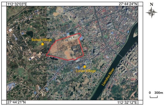
Figure 4.
Remote sensing imagery of the study area.
Based on the 3D model in Figure 5, the site of the study area is discretized into 3D grids of different sizes. Table 1 summarizes different settings of finite difference grids and the number of degrees of freedom in the simulation. The spatial resolutions of the 3D grids range from 10 m to 1 m, corresponding to a number of nodes with 1.08 million to 108 million degrees of freedom. Thus, our simulations cover high-resolution 3D simulation cases.
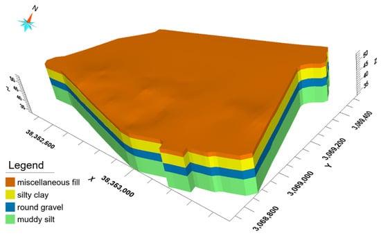
Figure 5.
3D model of the study area.

Table 1.
Summary of different settings of finite difference grids and the numbers of degrees of freedom.
Figure 6 illustrates the northwest boundary condition, which specifies the flux along the northwest boundaries, representing the lateral flow recharge northwest of the site. The southeast boundary condition is a specified-head boundary set uniformly to a constant. A uniform recharge rate of m/s is applied to the northwest boundary, and a water head of 48 m is used for the outflow boundary (southeast boundary) based on the river stage of the Lianshui River. The top boundary condition is defined as a flux-specific boundary representing the rainfall recharge at a rate of 1400 mm/yr based on the region’s annual precipitation. The bottom boundary condition is a no-flow boundary since the silty mudstone layer at the bottom of the aquifer is considered impermeable. In the solute transport model, all boundaries except the southeast (outflow) boundary are set to zero-mass flux. The mass flux for the southeast boundary is set to the outflow rate through the boundary. Besides the above boundary condition, the other model parameters are set according to our previous work [61].
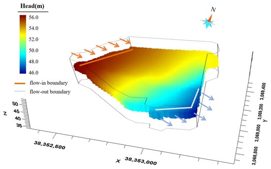
Figure 6.
Boundary condition for water head.
Given the above 3D grid models, boundary conditions, and model parameters, we use the finite difference method to discretize the models of groundwater flow and solute transport (Equations (1) and (2)). This discretization generates linear systems (Equation (3)) for the groundwater flow and transport simulations. The size of these linear systems is massive, corresponding to the number of nodes in the 3D grid models. We employ the dual-domain decomposition method to solve these extensive linear systems.
4. Results and Discussion
Our dual-domain decomposition method was implemented with C++. To validate the performance of our method, we conducted a comparative study on a PC equipped with an Intel i7 12700KF CPU with 12 cores and 20 threads and 32 GB RAM. The PC runs under the Windows 10 operating system. The numeric problems of groundwater flow and transport were tested. Various scenarios were designed with different degrees of freedom, ranging from 13.5 to 108 million. By default, the CG and CG-BISTAB algorithms are used to solve the sublinear systems over subdomains for the groundwater flow equation and the solute transport equation, respectively.
4.1. Performance of the Dual-Domain Decomposition Method
The efficiency of the dual-domain decomposition method is evidently dependent on the grain sizes of subdomains. To assess this dependency, we evaluated the performance of the proposed method with varying numbers of subdomains. Table 2 summarizes the number of iterations and solution times obtained with twenty threads in total employed in the proposed method. The results indicate that, for both groundwater flow and groundwater transport problems, both the timing and number of iterations of the proposed method generally decrease as the number of subdomains increases. This demonstrates that parallelizing the computation across more subdomains enables an improvement in solution performance. The performance continues to improve as the number of subdomains increases, surpassing the available number of threads. This is attributed to the finely grained partitioning of subdomains, resulting in smaller linear systems for each domain. While increasing the number of subdomains may lead to a large Schur system, our observations indicate that the solution remains efficient. This efficiency is maintained through the utilization of second-level domain decomposition methods during the solution process.

Table 2.
Performance statistics of the dual-domain decomposition method for groundwater flow and groundwater flow problems, including the number of degrees of freedom (#.dofs), number of subdomains (#.subdomains), number of iterations (#.iterations), time to obtain the solution of Schur system (Schur), and total solution time (total). The thresholds of the subdomains with the best performance in each scenario are highlighted in bold.
It is noteworthy that the performance begins to decline when the number of subdomains exceeds a certain threshold. This deterioration is attributed to the limited number of threads in our experiment, which are insufficient to efficiently process the increased number of subdomains. When the size of the subdomains is refined sufficiently, the solution time for sublinear problems associated with subdomains cannot be significantly reduced. Thus, the computations required to handle the increased number of subdomains and the larger Schur system outweigh the efficiency gains from smaller subdomain sizes. Conducting a grid test of the runtime, as shown in Table 2, to find the optimal number of subdomains is impractical. However, since the runtime for subproblems across different subdomains is generally similar, we can test the runtime of a single subdomain (using one thread) to estimate the overall runtime for different numbers of subdomains, thereby approximating the optimal number of subdomains. Anyway, the dual-domain decomposition method enables a fast solution of the Schur system over subdomain boundaries. This performance boost helps mitigate the impact of the increased size of the Schur system and allows us to focus more on the variation in runtime over subdomains when tuning the number of subdomains.
The number of subdomains in different grid resolutions can influence the convergence rates in solving the Schur system. Table 2 includes the number of iterations required to solve the Schur system. It is observed that the number of iterations progressively decreases as the number of subdomains increases. This indicates that our dual-domain decomposition preconditioner attains higher convergence rates for large Schur systems due to the finely grained partitioning of the domain, which includes more face and edge nodes. This is reasonable because finely grained subdomains result in a greater number of smaller boundary faces. Since we use approximations for the face nodes and no approximation for the boundary nodes in the preconditioning system in Equation (15), a smaller size for the boundary faces and more boundary edges between them facilitate a better preconditioning of the Schur system, thereby improving the convergence rates in solving the Schur system. A larger number of grids tends to generate more efficient solutions, and in such cases, the number of iterations is less sensitive to the grid resolution (Table 2). This characteristic enables the dual-domain decomposition method to scale effectively for high-resolution groundwater simulation problems.
4.2. Comparision with Dual-Domain Decomposition Method
To assess the efficiency gains of the proposed dual-domain decomposition method, specifically focusing on the impact of second-level domain decomposition on the Schur system, we conducted a comparative analysis with the vanilla domain decomposition method. Firstly, we evaluated the performance of the vanilla domain decomposition method across different numbers of subdomains. In the first evaluations, all 20 threads were employed for the solution of the vanilla domain decomposition method. Similar to the dual-domain decomposition method, the efficiency of the vanilla domain decomposition method increases with the number of subdomains (see Table 3). However, its efficiency peaks at a much smaller number of subdomains compared with that of the dual-domain decomposition method. Consequently, the efficiency of the vanilla method is significantly lower compared to that of the dual-domain decomposition method, particularly with larger numbers of subdomains. This difference is further magnified by speedup ratios of 8.617× (groundwater flow) and 4.541× (groundwater transport) when handling large linear systems with 108 million degrees of freedom.

Table 3.
Performance statistics of the vanilla domain decomposition method for groundwater flow and groundwater flow problems, including the number of degrees of freedom (#.dofs), number of subdomains (#.subdomains), number of iterations (#.iterations), time to obtain the solution of Schur system (Schur), and total solution time (total). The thresholds of the subdomains with the best performance in each scenario are highlighted in bold.
We further compared the performance of the vanilla algorithm using the same number of subdomains, as detailed in Table 4 and Table 5 and illustrated in Figure 7. All twenty threads were utilized to evaluate the efficiency of the vanilla domain decomposition method. The vanilla decomposition method exhibits a significant performance deterioration in timing compared with that of the dual-domain decomposition approach. This deterioration in performance becomes particularly noticeable with the larger sublinear systems and increased solution times for the Schur system. For linear systems with 108 million degrees of freedom, the dual-domain decomposition method achieves a 9.348× improvement in groundwater flow and a 6.788× improvement in groundwater transport.

Table 4.
Solution time, iterations, and acceleration ratio for groundwater flow problem at different scales.

Table 5.
Solution time, iterations, and acceleration ratio for groundwater transport problem at different scales.
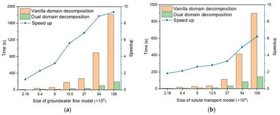
Figure 7.
Comparison of solution time and speedup ratio between dual-domain decomposition and vanilla domain decomposition methods at different model sizes. (a) Groundwater flow model; (b) Solute transport model.
When the vanilla domain decomposition method is used to solve the linear systems of the same size over subdomains in parallel, the performance deterioration is mainly due to bottlenecks in the solution of large Schur systems for the boundary nodes. Figure 8 illustrates a comparison of the convergence process in the solution of the Schur systems. Clearly, a fast convergence is observed in the dual decomposition method, highlighting the effectiveness of the second level domain decomposition method as a preconditioner for solving Schur systems.
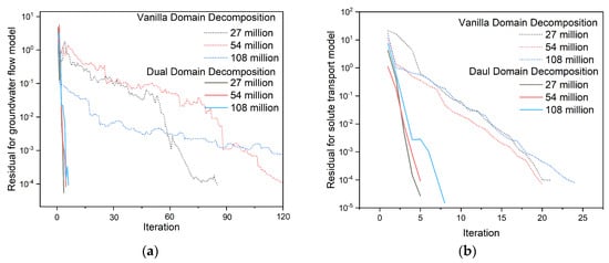
Figure 8.
Convergence comparison between dual-domain decomposition and vanilla domain decomposition methods at different model sizes: (a) Groundwater flow model; (b) Solute transport model.
In groundwater simulations over a time sequence, precomputed matrix factorization techniques as explained in Section 2.4 and Section 2.5 can accelerate the simulation of groundwater flow and transport processes. We compared the performance between the dual-domain decomposition and vanilla domain decomposition methods when employing the precomputation trick in time-sequential simulations. The groundwater flow and transport were simulated over 280 days (Figure 9), with a time differential step of 1 day. Table 6 and Figure 10 present the runtime and speedup values achieved in the time-sequential simulation. Our results demonstrate that the dual-domain decomposition method maintains a superior time efficiency compared to that of the vanilla domain decomposition approach, achieving a speedup of 8.46× with 108 million degrees of freedom.
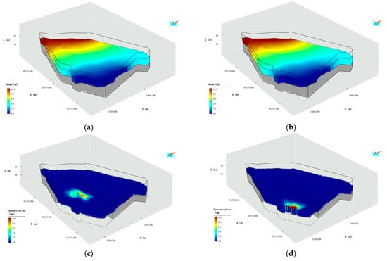
Figure 9.
Simulated hydraulic heads’ Cr(VI) concentrations at time steps of 100 days and 280 days ahead. (a) Head after 100 days; (b) Head after 280 days; (c) Concentration after 100 days; (d) Concentration after 280 days.

Table 6.
Performance comparisons of the dual-domain decomposition (DDD), the vanilla domain decomposition (VDD) with the optimal number of subdomains (Opt.), and the vanilla domain decomposition with same number of subdomains (Same) in time-sequential groundwater simulation.
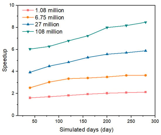
Figure 10.
Speedup of the ratio of the simulation process.
Figure 11 illustrates the memory consumption data. The groundwater flow and the groundwater transport problems are solved concurrently in the time sequence simulation, which requires a rather high memory overhead. Notably, the memory usage of the vanilla method with the optimal number of subdomains is significantly higher than that of the proposed method. Its memory requirements exceed the capacity of our testing PC in the case studied with 108 million degrees of freedom. This limitation prohibits the vanilla method from reaching its optimal timing, as shown in Table 6. The pre-computed matrix factorization requires of memory complexity for N-ordered linear systems. Therefore, a more finely grained partition of subdomains would improve the scalability of the domain decomposition method. However, this would also increase the size of the Schur system, adding computational burden for solutions. Thanks to the second level of domain decomposition, the proposed method enables a finely grained partition of subdomains while maintaining efficiency in the solution of the Schur system, with only a small compromise in memory overheads.
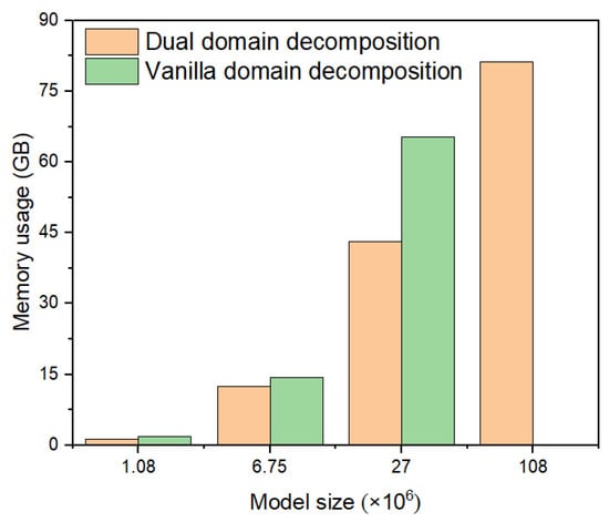
Figure 11.
Memory usage comparison for groundwater simulation at different model sizes.
4.3. Comparision with Algebraic Multigrid Preconditioned Method
Algebraic multigrid (AMG) methods represent a significant advancement in groundwater simulations. The AMG method has been widely recognized for its remarkable efficiency improvements in comparison to other Krylov subspace methods, such as CG and BiCGSTAB [34]. Many industrial groundwater simulation software packages integrate the AMG method as an advanced solver and/or preconditioner [62], often acknowledged as the fastest solver option in their toolkit.
In this context, we conducted a comparative analysis between the proposed method and an efficient parallel AMG preconditioner [63] implemented in PETSC [64]. Firstly, we assessed the runtime performance of the AMG method for solving groundwater flow and transport problems. Following a setup similar to that used for testing the proposed method, we tested problem sizes ranging from 2.16 to 108 million degrees of freedom. Table 7 presents the solution times achieved by the AMG method for the groundwater flow and transport problems. Additionally, Figure 12 provides a comparison of the runtime performance between the AMG method and the proposed method. The results demonstrate that the dual-domain decomposition method consistently outperforms the AMG preconditioned method across both groundwater flow and transport simulations, regardless of the problem size. The speedup ratios achieved by the dual-domain decomposition method are particularly noteworthy, reaching up to approximately 5× for the simulation with 108 million degrees of freedom.

Table 7.
Performance comparison between the algebraic multigrid (AMG) preconditioned method and dual-domain decomposition (DDD) method for groundwater flow and transport problems with different numbers of degree of freedom (#.dof).
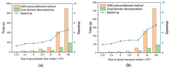
Figure 12.
Runtime and speedup comparison between dual-domain decomposition method and algebraic multigrid preconditioned method: (a) Groundwater flow model; (b) Solute transport model.
We further evaluated the performance of the AMG preconditioned method in time-sequential simulations, as outlined in Table 8. In this evaluation, groundwater flow and transport over 280 days are simulated. The results presented in Table 8 and Figure 13 illustrate a comparison between the AMG preconditioned method and the proposed method. It is evident that the proposed method significantly outperforms the AMG preconditioned method in time-sequential simulations. Particularly noteworthy is the substantial increase in speedup ratios compared to those reported in Table 8 and Figure 13. This improvement is attributed to the dual-domain decomposition scheme, which enables the reuse of matrix factorization to expedite the solution process.

Table 8.
Performance comparison between the algebraic multigrid (AMG) preconditioned method and the dual-domain decomposition (DDD) method in time-sequential groundwater simulation.
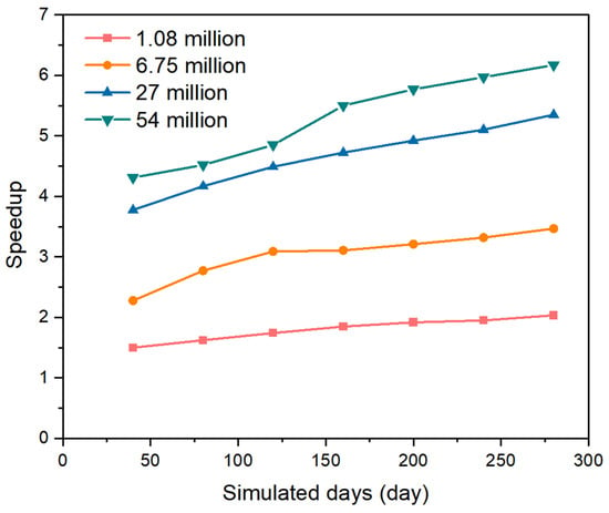
Figure 13.
Speedup ratios of the dual-domain decomposition (DDD) method compared with the algebraic multigrid (AMG) preconditioned method in time-sequential groundwater simulation.
Please note that the runtime of the AMG preconditioned method for the problem with 108 million degrees of freedom is not available (Table 8). This is due to the high level of memory usage for the AMG preconditioned method. For the problem with 108 million degrees of freedom, the memory usage exceeds the maximum system memory capacity. Therefore, besides its superior time efficiency, the proposed method also outperforms the AMG preconditioned method in terms of memory usage.
While the AMG preconditioned method [63] offers superior convergence rates compared to those of the vanilla Krylov subspace methods, the proposed method presents several advantages over the AMG method. Firstly, the proposed method is inherently parallel and incurs low communication and synchronization costs. Although the MG method can be parallelized, it often requires careful designing to maintain its efficiency, especially considering the high cost of inter-grid transfers. Consequently, the proposed method scales well in parallel systems, as each subdomain can be handled independently, making it efficient for extremely large groundwater simulation problems. Secondly, the nature of independent subdomains results in minimal memory requirements. Even with a second level of domain decomposition, the memory needed is related only to the scale of boundary nodes. In contrast, when addressing extremely large problems, the MG method requires a significant amount of memory due to managing multiple grid levels and ensuring efficient transfers between them. Overall, the proposed method achieves both time and memory efficiency in comparison to the AMG method.
5. Conclusions
In this paper, we propose a novel dual-domain decomposition method designed for groundwater flow and transport simulations. In summary, our method achieves the following contributions and key findings:
- (1)
- An additional level of domain decomposition is strategically devised to address the efficiency problem associated with solving the Schur system, a common bottleneck in vanilla domain decomposition methods. The tailored domain decomposition preconditioner enables the parallelization of the preconditioning process, ensuring a faster convergence rate compared with that of traditional Neumann–Neumann preconditioners when solving the Schur system;
- (2)
- The enhanced efficiency afforded by the proposed method allows for the partitioning of large-scale groundwater simulation problems into finely grained subdomains. This significantly reduces the computational overhead required for solving subdomains, resulting in notable speedups and memory savings during the solution process;
- (3)
- Compared to the vanilla domain decomposition method, our approach achieves efficient performance boosts in solving the Schur system and thus enables finely grained subdomains. For an extremely large groundwater flow and transport problem with 108 million degrees of freedom, these characteristics lead to 8.617× and 4.541× speedups for groundwater flow and transport scenarios, respectively, and enable the use of a precomputed matrix factorization trick with an optimal number of subdomains to enhance its performance in time-sequential simulations;
- (4)
- Compared to the AMG preconditioned method, our approach offers a well-established parallelization mechanism and lower memory costs. When solving a problem with 108 million degrees of freedom, these characteristics result in 4.643× and 5.515× speedups for groundwater flow and transport scenarios, respectively. Moreover, our method supports efficient time-sequential simulations, which are not feasible with the AMG preconditioned method due to memory overload.
The limitation of the proposed method is the difficulty in specifying the optimal number of subdomains, a challenge inherited from the vanilla domain decomposition method. While we propose a low-cost heuristic approach to determine the number of subdomains, fine-tuning this number still requires grid testing. In the future, we will incorporate the machine learning techniques, such as Bayesian optimization, into the heuristic to infer the optimal number of subdomains. Since the relationship between the number of subdomains and the solution time can be regarded as a convex function, machine learning techniques can be promising in finding a well-tuned number of subdomains in only a few low-cost attempts. This would result in sufficiently finely grained subdomains, thus unlocking the full potential of the domain decomposition scheme for efficiently simulating large-scale, high-resolution, and long-term 3D groundwater simulations.
Author Contributions
Conceptualization, H.D.; methodology, H.D. and J.L.; software, J.L.; validation, J.L., Y.L. and H.D.; formal analysis, J.L., J.H. and Y.Z. (Yang Zheng); investigation, Y.Z. (Yanhong Zou); resources, J.H. and Y.Z. (Yanhong Zou); data curation, J.H. and Y.Z. (Yanhong Zou); writing—original draft preparation, H.D.; writing—review and editing, H.D.; visualization, Y.C.; supervision, X.M.; project administration, X.M.; funding acquisition, Y.Z. (Yanhong Zou). All authors have read and agreed to the published version of the manuscript.
Funding
This study was supported by grants from the National Key Research and Development Program of China (Grant No. 2019YFC1805905), Water Conservancy Science and Technology Project of Guizhou Province (No. KT202410), Open Research Fund Program of Key Laboratory of Metallogenic Prediction of Nonferrous Metals and Geological Environment Monitoring (Central South University), Ministry of Education (2022YSJS14), the National Natural Science Foundation of China (Grant Nos. 42272344, 42172328 and 72088101), and the Science and Technology Innovation Program of Hunan Province (2021RC4055).
Data Availability Statement
Data are contained within the article.
Acknowledgments
We would like to thank Xi Wang and Xinyue Li for their assistance with the experimental data.
Conflicts of Interest
The authors declare no conflicts of interest.
Appendix A. Algorithm for Solution of Schur Complement System
We use CG or BiCGSTAB to solve Schur systems derived from the dual-domain decomposition method. Algorithm A1 provides the pseudo-code of the BiCGSTAB solver of Schur system, where the subscripts , , and represent , , and or , , and in Algorithms 1 and 2. The function SchurSystemSolver implements the BiCGSTAB solver, while the function ComputeSchurComplementSystem computes the or in BiCGSTAB according to Equations (8a) and (18a), respectively.
| Algorithm A1. BiCGSTAB Solver of Schur system |
| >// Compute of according to Equations (8a) and (18a) function ComputeSchurComplementSystem(, , , , ) parallel for do ← ← LinearSolver() ← end parallel for ← return end // BiCGSTAB for Solution of Equations (7) and (16) function SchurSystemSolver(, , , , , Precondioner, PrecondParam) ← InitialGuess() ← ComputeSchurComplementSystem // ← ← ← ← ← ← ← for = 1, 2, 3, … ← ← ← ← Precondioner(PrecondParam, ) // ← ComputeSchurComplementSystem // ← ← ← Precondioner(PrecondParam, ) // ← ← Precondioner(PrecondParam, ) // ← ← if converges then break ← end for return end |
References
- Herbert, A.; Jackson, C.; Lever, D. Coupled groundwater flow and solute transport with fluid density strongly dependent upon concentration. Water Resour. Res. 1988, 24, 1781–1795. [Google Scholar] [CrossRef]
- Tompson, A.F.; Gelhar, L.W. Numerical simulation of solute transport in three-dimensional, randomly heterogeneous porous media. Water Resour. Res. 1990, 26, 2541–2562. [Google Scholar] [CrossRef]
- Scheibe, T.; Yabusaki, S. Scaling of flow and transport behavior in heterogeneous groundwater systems. Adv. Water Resour. 1998, 22, 223–238. [Google Scholar] [CrossRef]
- Voss, C.I.; Provost, A.M. SUTRA: A Model for 2D or 3D Saturated-Unsaturated, Variable-Density Ground-Water Flow with Solute or Energy Transport; US Geological Survey: Reston, VA, USA, 2002.
- Haws, N.W.; Rao, P.S.C.; Simunek, J.; Poyer, I.C. Single-porosity and dual-porosity modeling of water flow and solute transport in subsurface-drained fields using effective field-scale parameters. J. Hydrol. 2005, 313, 257–273. [Google Scholar] [CrossRef]
- Neven, K.; Sorab, P. Modeling of groundwater flow and transport in coastal karst aquifers. Hydrogeol. J. 2021, 29, 249–258. [Google Scholar]
- Konikow, L.F. The secret to successful solute-transport modeling. Groundwater 2011, 49, 144–159. [Google Scholar] [CrossRef] [PubMed]
- Deng, H.; Zhou, S.; He, Y.; Lan, Z.; Zou, Y.; Mao, X. Efficient calibration of groundwater contaminant transport models using bayesian optimization. Toxics 2023, 11, 438. [Google Scholar] [CrossRef] [PubMed]
- Esposito, J.M.; Kumar, V.; Pappas, G.J. Accurate event detection for simulating hybrid systems. In Proceedings of the Hybrid Systems: Computation and Control: 4th International Workshop, HSCC 2001, Rome, Italy, 28–30 March 2001; Proceedings 4. pp. 204–217. [Google Scholar]
- Maxwell, R.; Condon, L.; Kollet, S. A high-resolution simulation of groundwater and surface water over most of the continental US with the integrated hydrologic model ParFlow v3. Geosci. Model Dev. 2015, 8, 923–937. [Google Scholar] [CrossRef]
- Park, Y.-J.; Sudicky, E.; Panday, S.; Sykes, J.; Guvanasen, V. Application of implicit sub-time stepping to simulate flow and transport in fractured porous media. Adv. Water Resour. 2008, 31, 995–1003. [Google Scholar] [CrossRef]
- Sreekanth, J.; Moore, C. Novel patch modelling method for efficient simulation and prediction uncertainty analysis of multi-scale groundwater flow and transport processes. J. Hydrol. 2018, 559, 122–135. [Google Scholar] [CrossRef]
- Wang, H.; Fu, X.; Wang, G.; Li, T.; Gao, J. A common parallel computing framework for modeling hydrological processes of river basins. Parallel Comput. 2011, 37, 302–315. [Google Scholar] [CrossRef]
- Van der Vorst, H.A. Bi-CGSTAB: A fast and smoothly converging variant of Bi-CG for the solution of nonsymmetric linear systems. SIAM J. Sci. Stat. Comput. 1992, 13, 631–644. [Google Scholar] [CrossRef]
- Meyer, P.D.; Valocchi, A.J.; Ashby, S.F.; Saylor, P.E. A numerical investigation of the conjugate gradient method as applied to three-dimensional groundwater flow problems in randomly heterogeneous porous media. Water Resour. Res. 1989, 25, 1440–1446. [Google Scholar] [CrossRef]
- Mahinthakumar, G.; Valocchi, A.J. Application of the connection machine to flow and transport problems in three-dimensional heterogeneous aquifers. Adv. Water Resour. 1992, 15, 289–302. [Google Scholar] [CrossRef]
- Saad, Y. Iterative Methods for Sparse Linear Systems; SIAM: Philadelphia, PA, USA, 2003. [Google Scholar]
- Trottenberg, U.; Oosterlee, C.W.; Schuller, A. Multigrid; Elsevier: Amsterdam, The Netherlands, 2000. [Google Scholar]
- Ashby, S.F.; Falgout, R.D. A parallel multigrid preconditioned conjugate gradient algorithm for groundwater flow simulations. Nucl. Sci. Eng. 1996, 124, 145–159. [Google Scholar] [CrossRef]
- Watson, I.; Crouch, R.; Bastian, P.; Oswald, S. Advantages of using adaptive remeshing and parallel processing for modelling biodegradation in groundwater. Adv. Water Resour. 2005, 28, 1143–1158. [Google Scholar] [CrossRef]
- Sinha, E.; Minsker, B.S. Multiscale island injection genetic algorithms for groundwater remediation. Adv. Water Resour. 2007, 30, 1933–1942. [Google Scholar] [CrossRef]
- Beisman, J.J.; Maxwell, R.M.; Navarre-Sitchler, A.K.; Steefel, C.I.; Molins, S. ParCrunchFlow: An efficient, parallel reactive transport simulation tool for physically and chemically heterogeneous saturated subsurface environments. Comput. Geosci. 2015, 19, 403–422. [Google Scholar] [CrossRef]
- Le, P.V.; Kumar, P.; Valocchi, A.J.; Dang, H.-V. GPU-based high-performance computing for integrated surface–sub-surface flow modeling. Environ. Model. Softw. 2015, 73, 1–13. [Google Scholar] [CrossRef]
- Verkaik, J.; Van Engelen, J.; Huizer, S.; Bierkens, M.F.; Lin, H.; Essink, G.O. Distributed memory parallel computing of three-dimensional variable-density groundwater flow and salt transport. Adv. Water Resour. 2021, 154, 103976. [Google Scholar] [CrossRef]
- Garrett, C.A.; Huang, J.; Goltz, M.N.; Lamont, G.B. Parallel real-valued genetic algorithms for bioremediation optimization of TCE-contaminated groundwater. In Proceedings of the 1999 Congress on Evolutionary Computation-CEC99 (Cat. No. 99TH8406), Washington, DC, USA, 6–9 July 1999. [Google Scholar]
- Wu, Y.-S.; Zhang, K.; Ding, C.; Pruess, K.; Elmroth, E.; Bodvarsson, G. An efficient parallel-computing method for modeling nonisothermal multiphase flow and multicomponent transport in porous and fractured media. Adv. Water Resour. 2002, 25, 243–261. [Google Scholar] [CrossRef]
- Mills, R.T.; Lu, C.; Lichtner, P.C.; Hammond, G.E. Simulating subsurface flow and transport on ultrascale computers using PFLOTRAN. J. Phys. Conf. Ser. 2007, 78, 012051. [Google Scholar] [CrossRef]
- Wei, X.; Bailey, R.T.; Records, R.M.; Wible, T.C.; Arabi, M. Comprehensive simulation of nitrate transport in coupled surface-subsurface hydrologic systems using the linked SWAT-MODFLOW-RT3D model. Environ. Model. Softw. 2019, 122, 104242. [Google Scholar] [CrossRef]
- Mahinthakumar, G. Pgrem3d: Parallel Groundwater Transport and Remediation Codes. Users Guide. 1999. Available online: http://www4.ncsu.edu/~gmkumar/pgrem3d.pdf (accessed on 20 May 2024).
- Šimůnek, J.; Vogel, T.; van Genuchten, M.T. The SWMS-2D-Code for Similating Water Flow and Solute Transport in Two-Dimensional Variably Saturated Media: Version 1.2; US Salinity Laboratory: Riverside, CA, USA, 1994.
- Braess, D.; Dahmen, W.; Wieners, C. A multigrid algorithm for the mortar finite element method. SIAM J. Numer. Anal. 1999, 37, 48–69. [Google Scholar] [CrossRef]
- Brito-Loeza, C.; Chen, K. Multigrid algorithm for high order denoising. SIAM J. Imaging Sci. 2010, 3, 363–389. [Google Scholar] [CrossRef]
- Kourakos, G.; Harter, T. Parallel simulation of groundwater non-point source pollution using algebraic multigrid preconditioners. Comput. Geosci. 2014, 18, 851–867. [Google Scholar] [CrossRef]
- Sbai, M.A.; Larabi, A. On solving groundwater flow and transport models with algebraic multigrid preconditioning. Groundwater 2021, 59, 100–108. [Google Scholar] [CrossRef]
- Ji, X.; Cheng, T.; Wang, Q. CUDA-based solver for large-scale groundwater flow simulation. Eng. Comput. 2012, 28, 13–19. [Google Scholar] [CrossRef]
- Carlotto, T.; da Silva, R.V.; Grzybowski, J.M.V. A GPGPU-accelerated implementation of groundwater flow model in unconfined aquifers for heterogeneous and anisotropic media. Environ. Model. Softw. 2018, 101, 64–72. [Google Scholar] [CrossRef]
- Sun, H.; Ji, X.; Wang, X.-S. Parallelization of groundwater flow simulation on multiple GPUs. In Proceedings of the 3rd International Conference on High Performance Compilation, Computing and Communications, Xi’an, China, 8–10 March 2019; pp. 50–54. [Google Scholar]
- Ji, X.; Luo, M.; Wang, X.S. Accelerating streamline tracking in groundwater flow modeling on GPUs. Groundwater 2020, 58, 638–644. [Google Scholar] [CrossRef]
- Hou, Q.; Miao, C.; Chen, S.; Sun, Z.; Karemat, A. A Lagrangian particle model on GPU for contaminant transport in groundwater. Comput. Part. Mech. 2023, 10, 587–601. [Google Scholar] [CrossRef]
- Schwarz, H.A. Ueber einige Abbildungsaufgaben. J. Reine Angew. Math. 1869, 1869, 105–120. [Google Scholar]
- Chan, T.F. Third International Symposium on Domain Decomposition Methods for Partial Differential Equations; SIAM: Philadelphia, PA, USA, 1990. [Google Scholar]
- Ewing, R.E. A survey of domain decomposition techniques and their implementation. Adv. Water Resour. 1990, 13, 117–125. [Google Scholar] [CrossRef]
- Beckie, R.; Wood, E.F.; Aldama, A.A. Mixed finite element simulation of saturated groundwater flow using a multigrid accelerated domain decomposition technique. Water Resour. Res. 1993, 29, 3145–3157. [Google Scholar] [CrossRef]
- Elmroth, E.; Ding, C.; Wu, Y.-S. High performance computations for large scale simulations of subsurface multiphase fluid and heat flow. J. Supercomput. 2001, 18, 235–258. [Google Scholar] [CrossRef]
- Jenkins, E.W.; Kees, C.E.; Kelley, C.T.; Miller, C.T. An aggregation-based domain decomposition preconditioner for groundwater flow. SIAM J. Sci. Comput. 2001, 23, 430–441. [Google Scholar] [CrossRef]
- Gräsle, W.; Kessels, W. A RAM-economizing domain decomposition technique for regional high-resolution groundwater simulation. Hydrogeol. J. 2003, 11, 304–310. [Google Scholar] [CrossRef]
- Discacciati, M. Domain Decomposition Methods for the Coupling of Surface and Groundwater Flows; EPFL: Lausanne, Switzerland, 2004. [Google Scholar]
- Huang, Y.; Zhou, Z.; Wang, J.; Dou, Z. Simulation of groundwater flow in fractured rocks using a coupled model based on the method of domain decomposition. Environ. Earth Sci. 2014, 72, 2765–2777. [Google Scholar] [CrossRef]
- Xie, Y.; Wu, J.; Xue, Y.; Xie, C.; Ji, H. A domain decomposed finite element method for solving Darcian velocity in heterogeneous porous media. J. Hydrol. 2017, 554, 32–49. [Google Scholar] [CrossRef]
- Liang, D.; Zhou, Z. The conservative splitting domain decomposition method for multicomponent contamination flows in porous media. J. Comput. Phys. 2020, 400, 108974. [Google Scholar] [CrossRef]
- Taylor, G.I. Dispersion of soluble matter in solvent flowing slowly through a tube. Proc. R. Soc. Lond. Ser. A Math. Phys. Sci. 1953, 219, 186–203. [Google Scholar]
- Bear, J. On the tensor form of dispersion in porous media. J. Geophys. Res. 1961, 66, 1185–1197. [Google Scholar] [CrossRef]
- Zheng, C.; Bennett, G.D. Applied Contaminant Transport Modeling; Wiley-Interscience New York: New York, NY, USA, 2002; Volume 2. [Google Scholar]
- Gaidamour, J.; Hénon, P. A parallel direct/iterative solver based on a Schur complement approach. In Proceedings of the 2008 11th IEEE International Conference on Computational Science and Engineering, Sao Paulo, Brazil, 16–18 July 2008; pp. 98–105. [Google Scholar]
- Aristidou, P.; Fabozzi, D.; Van Cutsem, T. Dynamic simulation of large-scale power systems using a parallel Schur-complement-based decomposition method. IEEE Trans. Parallel Distrib. Syst. 2013, 25, 2561–2570. [Google Scholar] [CrossRef]
- Jaysaval, P.; Shantsev, D.; de la Kethulle de Ryhove, S. Fast multimodel finite-difference controlled-source electromagnetic simulations based on a Schur complement approach. Geophysics 2014, 79, E315–E327. [Google Scholar] [CrossRef]
- Peiret, A.; Andrews, S.; Kövecses, J.; Kry, P.G.; Teichmann, M. Schur complement-based substructuring of stiff multibody systems with contact. ACM Trans. Graph. (TOG) 2019, 38, 1–17. [Google Scholar] [CrossRef]
- Ulybyshev, M.; Kintscher, N.; Kahl, K.; Buividovich, P. Schur complement solver for Quantum Monte-Carlo simulations of strongly interacting fermions. Comput. Phys. Commun. 2019, 236, 118–127. [Google Scholar] [CrossRef]
- Toselli, A.; Widlund, O. Domain Decomposition Methods-Algorithms and Theory; Springer Science & Business Media: Berlin/Heidelberg, Germany, 2004; Volume 34. [Google Scholar]
- Mathew, T.P. Domain Decomposition Methods for the Numerical Solution of Partial Differential Equations; Springer: Berlin/Heidelberg, Germany, 2008. [Google Scholar]
- Zou, Y.; Yousaf, M.S.; Yang, F.; Deng, H.; He, Y. Surrogate-Based Uncertainty Analysis for Groundwater Contaminant Transport in a Chromium Residue Site Located in Southern China. Water 2024, 16, 638. [Google Scholar] [CrossRef]
- Diersch, H.-J.G. FEFLOW: Finite Element Modeling of Flow, Mass and Heat Transport in Porous and Fractured Media; Springer Science & Business Media: Berlin/Heidelberg, Germany, 2013. [Google Scholar]
- May, D.A.; Sanan, P.; Rupp, K.; Knepley, M.G.; Smith, B.F. Extreme-scale multigrid components within PETSc. In Proceedings of the Platform for Advanced Scientific Computing Conference, Lausanne, Switzerland, 8–10 June 2016; pp. 1–12. [Google Scholar]
- Balay, S.; Abhyankar, S.; Adams, M.; Brown, J.; Brune, P.; Buschelman, K.; Dalcin, L.; Dener, A.; Eijkhout, V.; Gropp, W. PETSc Users Manual; Argonne National Laboratory: Lemont, IL, USA, 2019. [Google Scholar]
Disclaimer/Publisher’s Note: The statements, opinions and data contained in all publications are solely those of the individual author(s) and contributor(s) and not of MDPI and/or the editor(s). MDPI and/or the editor(s) disclaim responsibility for any injury to people or property resulting from any ideas, methods, instructions or products referred to in the content. |
© 2024 by the authors. Licensee MDPI, Basel, Switzerland. This article is an open access article distributed under the terms and conditions of the Creative Commons Attribution (CC BY) license (https://creativecommons.org/licenses/by/4.0/).