Article

A Structural Optimization of Urban Drainage Systems: An Optimization Approach for Mitigating Urban Floods

1
Key Laboratory of Urban Stormwater System and Water Environment, Ministry of Education, Beijing University of Civil Engineering and Architecture, Beijing 100044, China
2
Collaborative Innovation Center of Energy Conservation & Emission Reduction and Sustainable Urban-Rural Development in Beijing, Beijing 100044, China
*
Author to whom correspondence should be addressed.
Water 2024, 16(12), 1696; https://doi.org/10.3390/w16121696
Submission received: 10 May 2024 / Revised: 1 June 2024 / Accepted: 12 June 2024 / Published: 14 June 2024
(This article belongs to the Special Issue Urban Flooding Control and Sponge City Construction)

Abstract

:
Urbanization and climate change increasingly challenge urban water management. In this context, the design of stormwater drainage systems, which traditionally relies on historical rainfall records, is being questioned. Although significant efforts have been dedicated to optimizing drainage networks, the upgrading of existing systems remains understudied. This research devised a set of viable stormwater drainage networks, referencing the road network of the Sino-Singapore Tianjin Eco-City (data from Google Maps). On this basis, utilizing design rainfall data (sourced from the local meteorological center), an extensive array of scenario analyses was conducted. The investigation assessed the performance of implementing two redundancy-based interventions—introducing loops and enlarging pipe diameters—as well as the patterns of flood risk response, and by integrating a multi-objective optimization algorithm, this study proposes a framework for the optimization of grey infrastructure upgrades based on component replacement. The findings suggest that a precise deployment strategy for grey infrastructure is essential. The former improves the effective flow distribution of the drainage system, while the latter enhances its flow capacity, making each intervention suitable for drainage systems with a different degree of centralization. Further research shows that an integrated hybrid scheme brings significant flood risk improvement with strong applicability for most urban drainage systems. The upgrade model proposed in this study could be a valuable initiative, offering theoretical insights for the construction and development of resilient cities.

1. Introduction

Under the dual driving forces of accelerating urbanization and exacerbated climate change, the frequency of urban flooding is on the rise [1,2,3,4]. The property losses and personal safety threats caused by urban flooding and erosion pose significant challenges to urban water safety management [5,6,7]. The urban stormwater drainage network, as a crucial component of the municipal infrastructure, aids cities in defending against storm threats by rapidly transporting and scheduling surface runoff [8]. Traditional designs predominantly feature a centralized layout, a structural paradigm that enhances the efficiency and controllability of the drainage system while mitigating the risks associated with flooding. Although this design has significantly safeguarded public safety in densely populated urban areas for nearly two centuries [9], it is predicated on past rainfall records that are presumed to be stable [10]. Relying solely on traditional design patterns is insufficient to address the challenges of future uncertainty risks [11].
Several studies have indicated that adopting a decentralized design in the topological layout during the planning phase of stormwater drainage networks offers distinct advantages in terms of reducing capital investment and enhancing resilience. Obando et al. [12] proposed a decentralized real-time control algorithm based on replicator dynamics, which decomposes the urban drainage system (UDS) into subsystems with specific topological structures. Research indicates that decentralized design not only reduces the computational complexity of real-time control (RTC) but also effectively mitigates flooding, making it suitable for application in large-scale UDSs. Bakhshipour and Haghighi et al. [13], building upon centralized drainage networks, developed the hanging garden algorithm, capable of generating decentralized layouts with arbitrary degrees of centralization. The evaluation results using the hydraulic performance index (HPI) demonstrate that decentralized layouts surpass traditional centralized configurations in terms of hydraulic performance. Hesarkazzazi et al. [14] also found that, regardless of whether the terrain is flat or steep, the flow distribution characteristics of decentralized layouts are more helpful in reducing flood risk, especially during extreme storm events. Wang et al. [15] studied the environmental and economic impacts of centralized versus decentralized drainage networks and found that decentralized layouts impose fewer environmental and economic burdens.
However, considering financial, social, technological, and environmental factors, the transition from centralized to decentralized systems in most cities is challenging to achieve. Instead, localized structural updates and interventions that enhance the overall adaptability of the system can serve as a viable alternative. Mugume et al. [16] suggest that reinforcing interventions in the system can influence its hydraulic performance. For instance, redundancy during the design, renovation, or repair process can affect the system’s ability to withstand service disruptions, thereby enabling a rapid return to an acceptable level of performance during storm events. Redundancy [17,18] is defined as the degree of functional overlap within a system (the number of components with the same function), allowing the system to accommodate changes and maintain its basic functions even when certain components take on new roles or are damaged. Redundancy can be achieved by providing additional storage capacity, such as incorporating detention tanks, enlarging the diameter of key pipes, or adding alternative flow paths (creating loops). These measures, by improving the hydraulic conditions at critical locations, adjust the spatial and temporal distribution of inflows into the system, reducing the likelihood of flood events and thus enhancing its adaptability.
In terms of reliability, looped networks are commonly found in pressurized water supply networks [19], and are less common in tree-like drainage networks. However, considering the cost benefits of local structural adjustments and the principle of effective water flow distribution, the construction of loops (alternative flow paths) as an intervention to enhance the resilience of drainage systems remains theoretically feasible. Yazdi et al. [20], in their search for solutions to enhance the resilience of UDSs, found that adding redundant paths around system bottlenecks is more effective in mitigating flooding and improving system resilience than traditional methods, such as using detention ponds and enlarging channel dimensions. Lu et al. [21], in a comparative study of branched and looped drainage pipes in Dongying, China, found that the peak runoff at the outlets of looped systems was significantly lower than that of branched networks. Subsequently, Lu et al. [22] developed a framework for the optimal network structure of UDSs considering pipe redundancy, and the results showed that the total overflow volume of UDSs with looped pipes was reduced by 20% to 30%. Reyes-Silva et al. [23] described the topological structure of drainage networks in terms of meshness, and studied the relationship between topology and node flooding, finding that networks with higher meshness had fewer and shorter flood events at nodes, and smaller overflow volumes. Hesarkazzazi et al. [24] added looped paths to both centralized and decentralized drainage networks to analyze the impact of redundant interventions on system resilience, and the results indicated that implementing redundant paths could increase the system’s recovery performance under functional failures by nearly 10% without altering the main structural characteristics of the network, such as sewer diameter, length, and storage capacity.
Additionally, the size of the pipes determines the capacity of the drainage system to handle and convey water flow, which is directly related to the system’s hydraulic performance during rainfall events. On one hand, larger pipe sizes imply greater storage capacity, which can reduce the decline in pipe transmission capability due to overloading. This means that during storm events that exceed the design standards, the system can still maintain a certain level of its original functionality. On the other hand, larger pipe diameters can provide faster drainage services, shorten recovery times, and reduce the damage caused by flooding; therefore, pipe size is often considered an important variable in optimizing drainage networks [25,26]. Ogidan et al. [27] found that by replacing pipe sizes and adding inline storage, the frequency of sewer overflows in the drainage network was significantly reduced. Hesarkazzazi et al. [28] explored the impact of pipe size on the resilience of stormwater networks using an iterative method to update (enlarge) the pipe sizes from top to bottom, indicating that under lower recurrence periods (around 20 years), part-full pipes enable the system to store more stormwater and effectively reduce surface flooding, thus achieving a more resilient solution. Liu et al. [29] proposed a new method for the reconstruction of drainage networks based on the assumption that expanding the capacity of downstream pipes can reduce overflow at upstream nodes. They found that the expansion of a specific pipeline diameter can significantly reduce system node overflow, with the maximum overflow volume in the studied case reduced by an average of 87.8% and the number of overloaded pipes reduced by 57.5%.
This study offers a novel perspective on enhancing the performance of urban drainage systems by constructing loops at specific locations within the system to establish additional flow paths and by enlarging the diameter of critical pipelines to expand the system’s storage capacity, thereby improving the existing system’s performance in response to storm events. Specifically, we utilize extensive scenario simulations guided by global enumeration and multi-objective optimization to search for the optimal spatial configuration of these two intervention patterns, and evaluate the hydraulic performance of the drainage system under their individual effects and corresponding alternative solutions implemented through integration, in order to provide guiding recommendations for urban rainwater management.

2. Materials and Methods

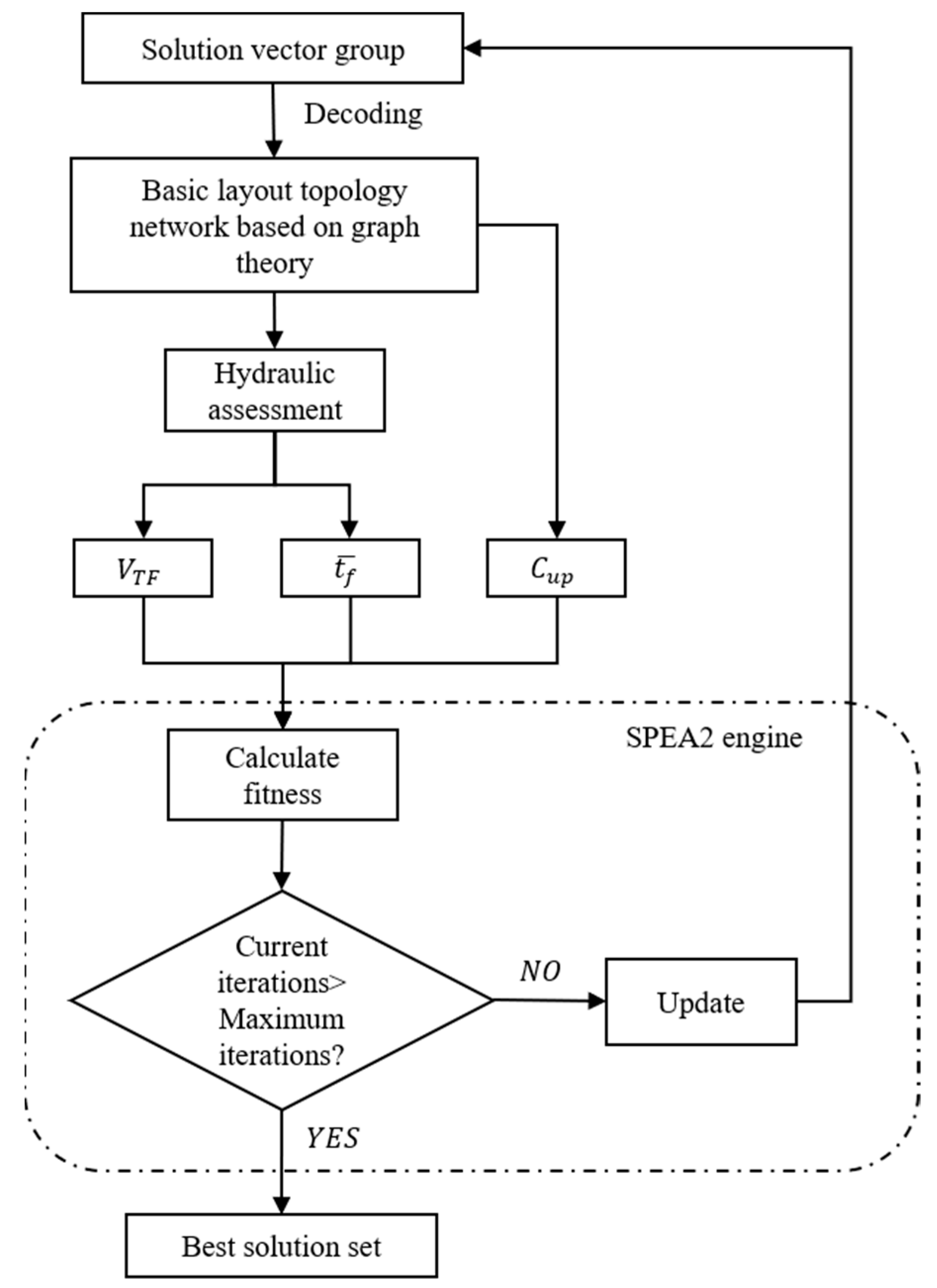
The study proposes a decision-making framework to support the planning and upgrading of UDSs, offering solutions related to the following three objectives: (1) under the constraints of hydraulic reliability, a graph-theoretic drainage network generation framework driven by genetic algorithms is utilized to obtain optimal solutions with varying degrees of decentralization; (2) redundancy features, including the pipe diameter enlarging (DE) and the loop-introducing (LI), are introduced to both centralized and decentralized drainage network layouts. A global approach is employed to explore the system’s performance response to changes in different structural characteristics and to analyze the flood mitigation effects under various storm events; and (3) a multi-objective optimization algorithm is applied to evaluate the effectiveness of hybrid mode (DE & LI) drainage systems, and recommended intervention patterns are provided for specific system layout. The logical framework of this article is shown in Figure 1.

2.1. Study Area

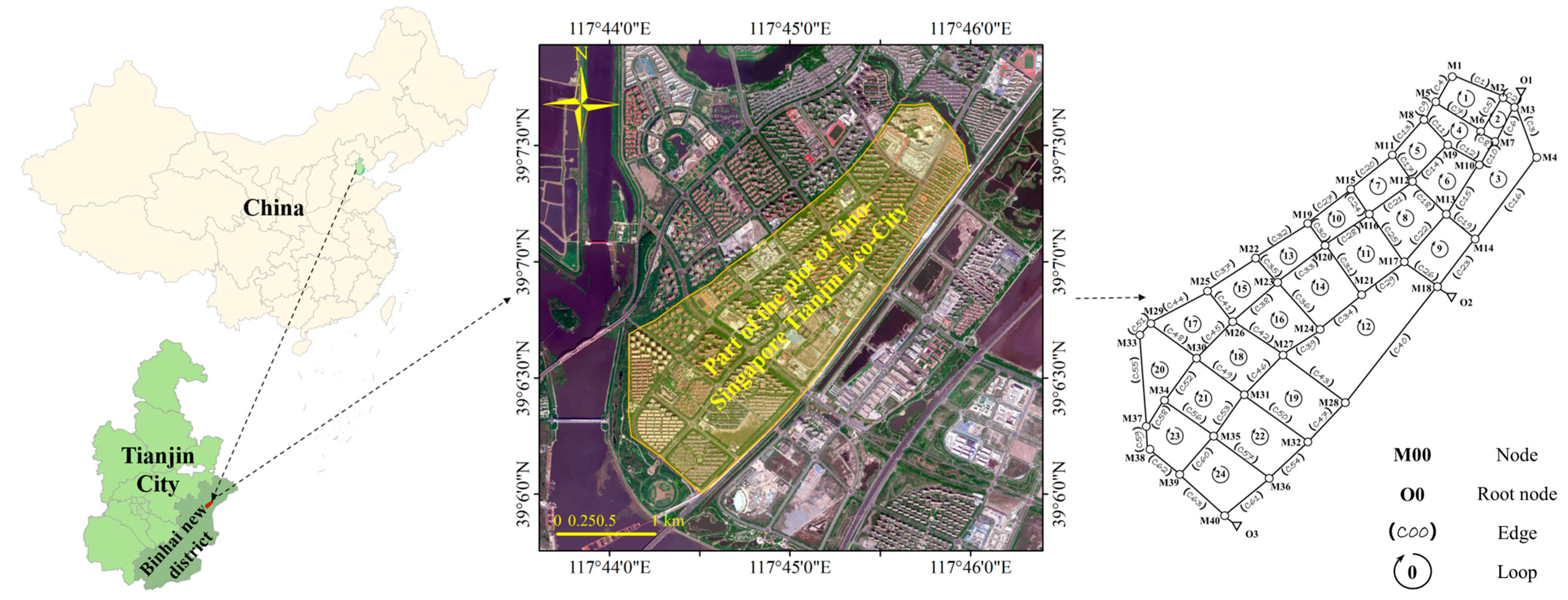
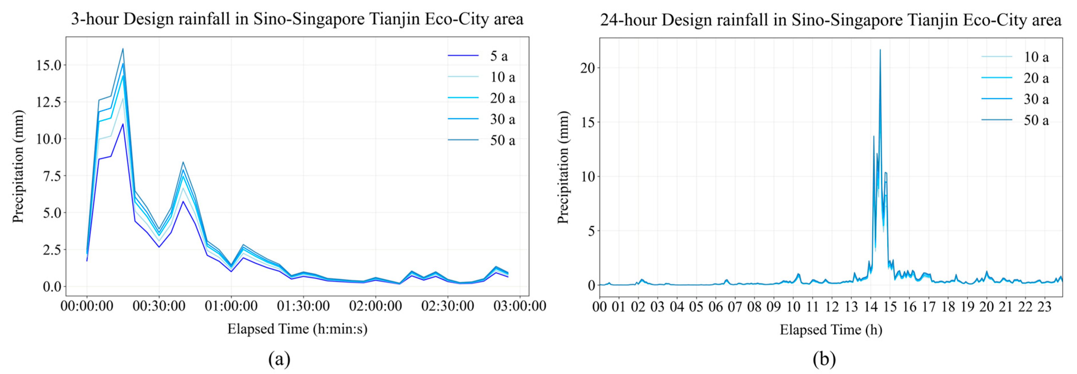
The study area is located in the eastern part of the Tianjin Eco-City pilot zone in the Binhai New Area of Tianjin, China (Figure 2). The region is characterized by flat terrain with a generally low gradient, covering an area of approximately 3.82 square kilometers. Situated in the mid-latitude region of the northern hemisphere, it has a continental semi-humid monsoon climate with pronounced seasonal precipitation patterns. The average annual precipitation is 602.9 mm, with most of the rainfall occurring in July and August, accounting for over half of the annual total. The drainage system in this basin often faces significant drainage pressure during the summer, and the flat terrain is also prone to urban flooding. Considering the strong correlation between the street network and urban water supply infrastructure, approximately 80% of the stormwater drainage pipe network is associated with 50% of the street network [30]. In this study, the design method of configuring rainwater drainage pipes along the main streets was adopted (we obtained road information for the study area from Google Maps). The hydrological and hydraulic model of the study area consists of 63 pipes, 40 manholes, and 3 candidate outlets. The sub-catchment area is divided into Voronoi diagrams using inspection wells as inputs. Land use type data are derived from band extraction of satellite images of the study area using OpenCV, and the design rainfall input is based on statistical calculations of multi-year rainfall data for the Sino-Singapore Eco-City area from the Tianjin Climate Center, as shown in Figure 3.
This study employed version 5.2 of the Storm Water Management Model (SWMM) by the United States Environmental Protection Agency (EPA) for the fundamental modeling of the stormwater drainage network. Widely utilized in the fields of urban planning, water resource management, and flood prevention, SWMM provides significant support and serves as a reference for urban water management. The Horton model and the dynamic wave method are applied for the hydraulic simulation of infiltration and the flow within the conduits, respectively.

2.2. Layout Generation of the Optimized Network

2.2.1. (De)centralized Layout Generator

This study employs a graph-theoretic approach to guide the layout generation process within an undirected graph composed of edges and nodes, where edges are considered as pipes and nodes as manholes. The initial undirected base graph is a full-mesh graph generated based on street topology, encompassing all layout possibilities. Figure 4 illustrates this process.
Initially, the base graph is processed using the loop-by-loop cutting algorithm (LLCA) [31], which eliminates all cyclical paths within the base graph. The ring-opening process is sequentially executed until the base graph is transformed into a minimum spanning tree with the outlet serving as the root node. A tree-like layout with a single outlet is referred to as a fully centralized layout, which serves as the input for the decentralized layout generation process.
The hanging garden algorithm (HGA) [13] is applied to further segment a centralized layout by inputting a predetermined number of candidate outlets, sequentially opening the shortest path between the newly defined drainage outlets and the existing layout drainage outlets. The system is then divided into subsystems with multiple outflow paths, resulting in layout schemes with different degrees of concentration. Now, the layout evolves from a single spanning tree to a forest of drainage networks constructed from multiple spanning trees, thereby creating a decentralized layout.
Assigning a set of predefined outlets to specific locations on the base graph (e.g., near rivers) requires the exploration of all possible outlet positions when searching for the optimal solution. The degree of centralization (DC) mentioned earlier quantifies the overall decentralization of the UDS from a redundancy perspective. It is expressed as the logarithmic relationship between the number of selected outlets N s o and the total number of candidate outlets N t o in the list of possible outlets. The expression is as shown in Equation (1):
D C = 100 × 1 l g N s o l g N t o
where D C (%) represents the degree of centralization, N s o is number of selected outlets, and N t o is total number of candidate outlets.

2.2.2. Hydraulic Component Designer

The layouts generated through graph-theoretic methods will be transferred to the hydraulic component design module to ascertain the dimensions of pipes and manholes, ensuring compliance with relevant design standards of the country or region:
  • The pipe diameters fall within the range between the maximum and minimum pipe diameters.
  • The downstream pipe diameter must not be smaller than the upstream pipe diameter.
  • Feasible commercial pipe diameters selected.
  • The flow velocity within the pipe must lie between the maximum and minimum allowable velocities.
  • The pipes must meet the minimum burial depth requirements.
This study employs the rank by rank allocating algorithm (RRAA) to implicitly meet the aforementioned constraints. The method utilizes a cascading allocation logic from upstream to downstream, delineating ranks by the shortest path from a given node to a designated root node (the number of nodes between them). Edges are also assigned a hierarchy based on the higher rank of the nodes they connect, and pipe diameters are allocated to all edges in descending order of rank. The diameter allocation is determined through Equation (2) as follows:
D i = D u p i + P i × 1000
where D i represents the allocated diameter for pipe segment i in millimeters (mm) and D u p i is the diameter of the upstream pipe connected to pipe segment i . If pipe segment i is the starting segment, the smallest commercially available pipe diameter is selected in mm. P i is a real number between 0 and 1 that determines the degree of similarity between the allocated diameter and the upstream diameter. The allocated pipe diameter D i will be selected from the actual commercially available pipe diameters.
Due to the design of stormwater drainage pipes utilizing gravity flow, the fullness degree is generally less than 1. When the runoff flows within the pipes as a free surface flow, the hydraulic gradient coincides with the pipe gradient. According to the Manning formula, by rearranging the pipes to accommodate the minimum flow velocity v m i n , it can be deduced that if the calculated minimum slope I m i n is satisfied, the restriction on the minimum flow velocity can be met.
v m i n = 1 n · R 2 3 · I 1 2
I m i n = n · v m i n R 2 3 2 = n · v m i n · χ 2 3 1 r s p A 2 3 2
where n represents the Manning coefficient; R is the hydraulic radius, m; I is the hydraulic gradient, m; χ is the wetted perimeter, m; r s p represents the ratio of free space in the pipe; and A is the cross-sectional area of the pipe, m 2 . When the slope of the buried drainage pipe is not less than the minimum design slope corresponding to the pipe diameter, it ensures compliance with the flow velocity requirements.

2.2.3. Optimization Engine

Considering that a feasible layout needs only to minimize construction costs while meeting hydraulic feasibility requirements, a simple single-objective optimization engine, the genetic algorithm (GA) [32], is employed. This algorithm simulates the natural evolutionary processes of selection, crossover, and mutation to search for the optimal solution set.
In this study, the objective function is defined as the construction cost, which can be expressed by Equation (5) as follows:
F c = i = 1 N e C i D i × L i + j = 1 N n C j ( H j )
where F c represents the total construction cost; N e is the number of drainage pipes; C i is the cost associated with pipe i , which is a function of the pipe’s diameter D i ; D i is the diameter of pipe i ; N n is the number of manholes; C j is the cost associated with manhole j , which is a function of the manhole’s depth H j ; and H j is the depth of manhole j .
Hydraulic reliability constraints are established in accordance with the design requirements for the central city stormwater network as stipulated in the Standard for design of outdoor wastewater engineering (GB50014-2021), which is a national standard in China, dictates that the designed system should not flood under a 5-year rainfall event (although pipe surcharge is permissible). Solutions that meet hydraulic reliability limitations and have lower F c have higher fitness rankings, while solutions that do not meet hydraulic limitations have their costs set to infinity to reduce fitness rankings.
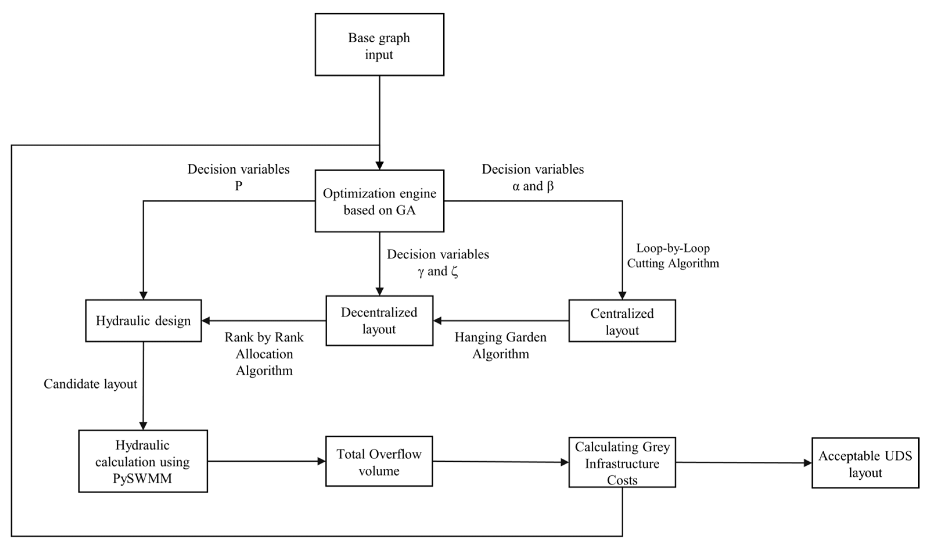
As depicted in Figure 5, The integration of the Python-based Storm Water Management Model (SWMM) interface, known as PySWMM (PySWMM 1.5.1), and GA into the proposed framework facilitates the search for feasible layouts. The iteration process will continue until the predetermined requirements are met before terminating. (Convergence is assumed to have been reached when the optimal solution exceeds 100 generations without updates).

2.3. Redundancy Intervention

2.3.1. Loop-Introducing

The LI is achieved by adding pipes to streets where no pipes currently exist, thereby fully connecting the pipeline layout originally built around the block into a looped structure [22,24]. It is noteworthy that, because the base graph encompasses all possible drainage pipe connections, these structures, when reflected in the UDS, represent the opposite operation to the loop-opening mentioned in Section 2.2. Although this step indeed counteracts the efforts made by the LLCA, it is logically necessary. For the hypothetical case in this study, candidate nodes for adding loops originate from the nodes added to the network during the layout generation process (the two endpoint nodes after the cutting of an edge/sewer in the base graph). However, for actual cases, this may require consideration of stakeholders’ preferences and practical pre-determinations.
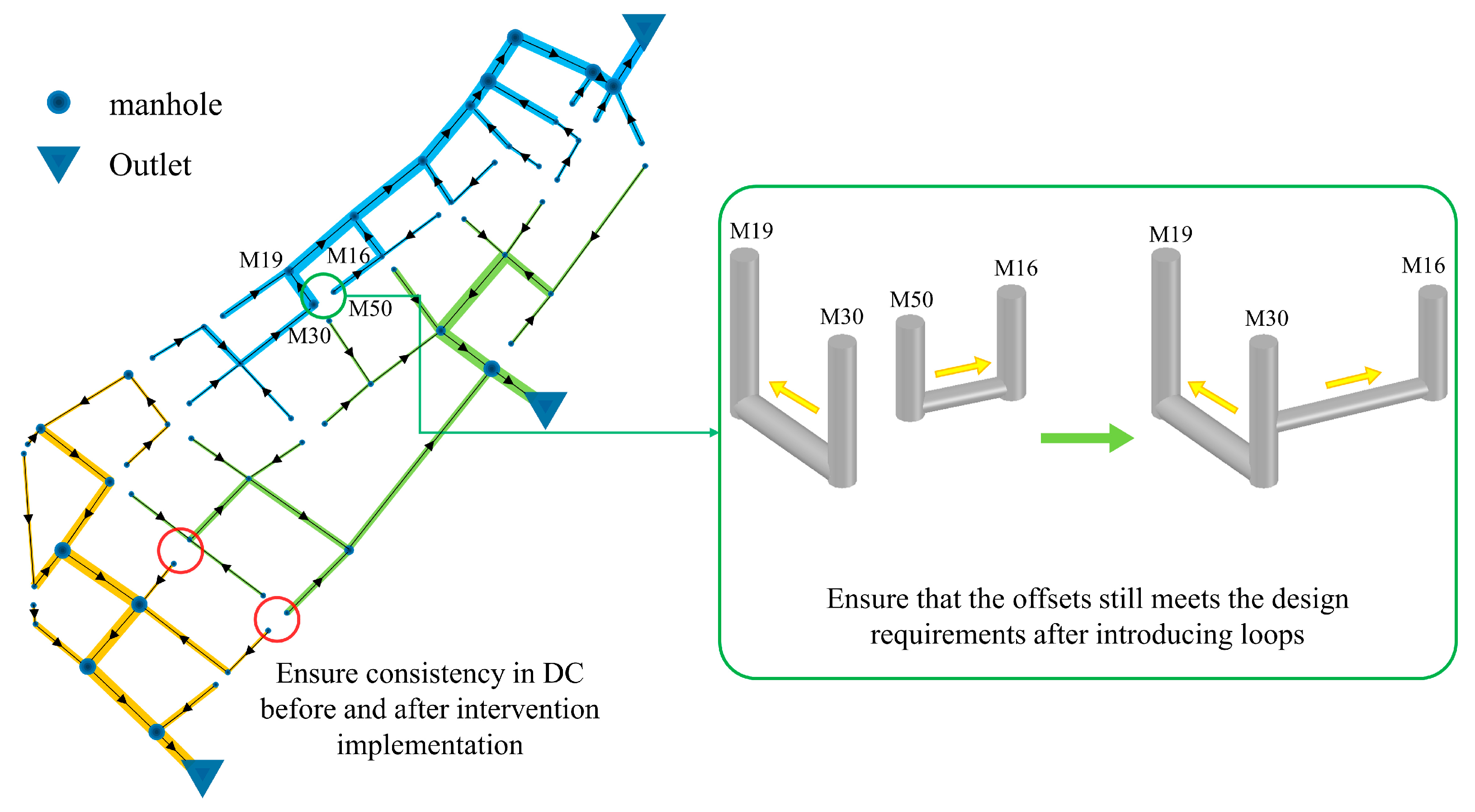
This method is readily implementable in a fully centralized layout. Nevertheless, in a decentralized layout, subsystems with different emission outlets cannot be connected to build loops, as this undermines the original degree of centralization of the system (as shown in Figure 6, the four nodes marked with red circles are located in different subsystems, and although connecting them could form a loop, it would compromise the current layout’s DC). Therefore, some candidate nodes in the decentralized layout should be pre-screened in advance.
To construct loops, pipe segments that do not fully cover the street’s catchment paths are selected as candidate locations for addition. These pipes connect nodes that are located at street hubs or intersections. As illustrated in Figure 6 with green circles, it is inevitable that, due to the difference in design depths of the manhole and its adjacent manholes (which are to be newly connected to form a looped layout), there will be a situation where the invert elevations of manhole bottoms vary. Considering that deeper manholes typically handle more flow, this study adopts a configuration where the deeper manhole overflows to the shallower one. This arrangement provides relief to the deeper manhole when it is under flow pressure.

2.3.2. Pipe Diameter Enlarging

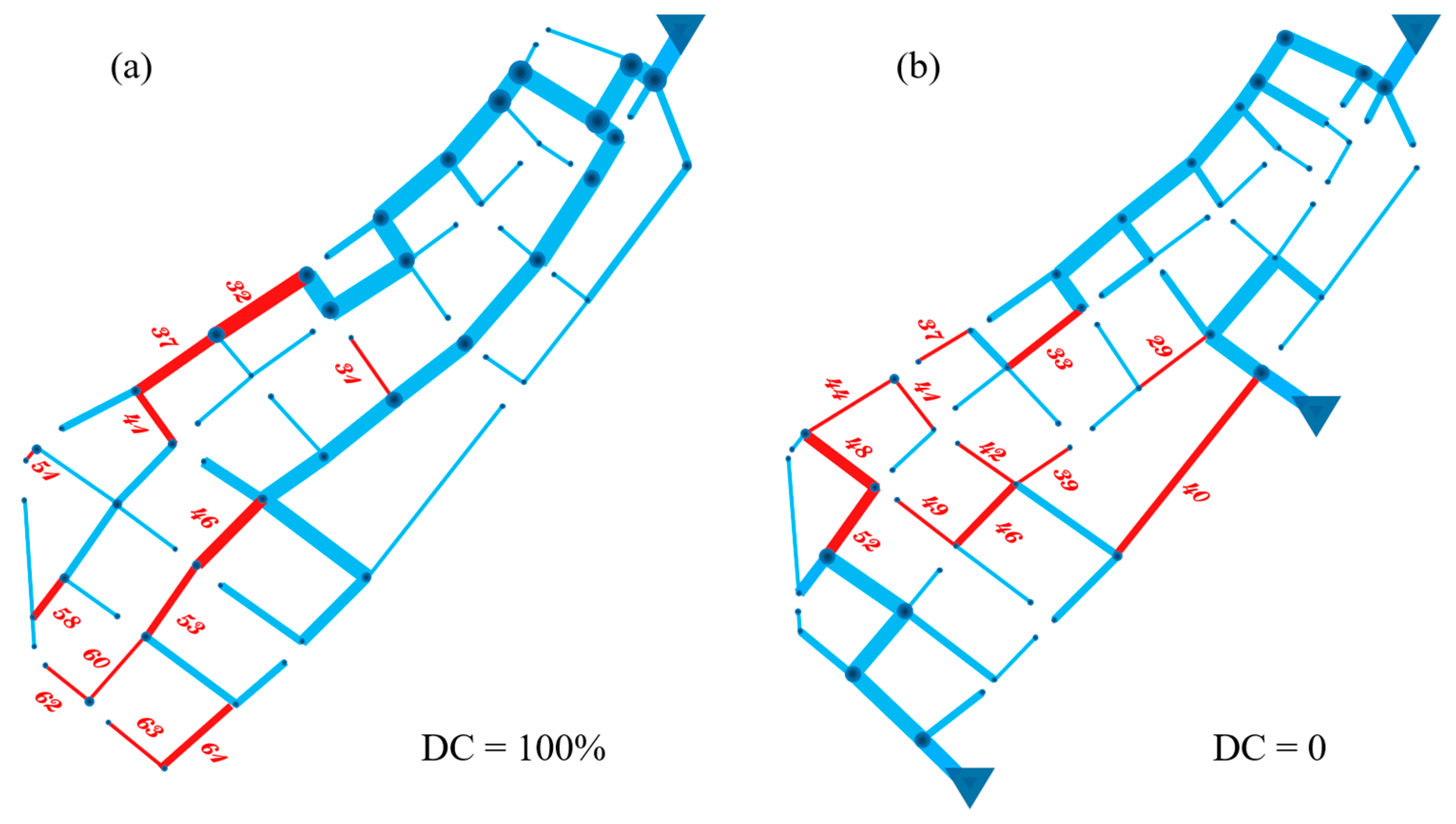
The DE is implemented by increasing the diameter of surcharged pipes, ranked in descending order by affected time, by one level in the commercial pipe diameter list [29,33]. This candidate list only includes pipes with diameters that are inconsistent with their downstream counterparts. Considering that a larger pipe diameter corresponds to a smaller slope—implying that the slope does not need to be readjusted after the pipe diameter change—the model modification process can be achieved through a simple operation while satisfying hydraulic constraints.
Under different return periods, the UDS experiences variations in spatial and temporal inflow conditions, leading to differences in the flow rates of the pipes. However, it is undeniable that as the return period increases, more pipes will face the predicament of surcharge, hindering the effective conveyance of runoff. Clearly, providing these pipes with greater storage capacity is an intuitive solution. To screen for a more adaptable list of replacement candidates, this study selects pipes that are consistently included in the surcharge list across different return periods and ranks them in descending order based on the weighted average of their overload impact time.

2.3.3. Hybrid Mode

Considering that the LI and the DE provide distinct performance improvements to the UDS by effectively allocating flow path and enhancing flow capacity, respectively, it is necessary to explore the impact of an integrated approach on the UDS. The hybrid intervention integrates the two intervention modes mentioned above, which are independently implemented in the UDS according to the intervention scale.
The hybrid intervention mode adopts a candidate pipeline list that consolidates the candidate pipelines from the two independent intervention schemes. Since the candidate pipelines for the LI and the DE are mutually independent and non-repetitive, there will be no conflict in the comparison of intervention scales.

2.3.4. Analysis Method

To systematically analyze the performance improvement rules brought by two independent redundant intervention modes to the UDS, a global analysis method is employed for the loop construction intervention mode and the pipe diameter enlargement intervention mode. As illustrated in Figure 7, after obtaining all candidate positions for addition in different layouts, pipes are added (or replaced) in the current layout from L-1 to L-j (maximum intervention scale) to implement redundant interventions. All feasible solutions under the current scale are traversed until all permutations and combinations of scenarios are executed. This process will generate C j 1 + C j 2 + C j 3 + + C j j , which is 2 n 1 possible scenarios (for scale n, there are C j n scenarios). During this process, the total overflow volume ( V T F ) and the average node flooding duration ( t f ¯ ) are selected as key indicators to quantify the system’s performance.
For hybrid schemes, considering the vast search space, a global analysis method would incur a significant computational expense. In this study, an improved strength pareto evolutionary algorithm 2 (SPEA2) [34] is utilized to construct an approximate optimal hybrid scheme search framework, aimed at obtaining feasible solutions under different intervention scales. Compared to the robust and performance stable non-dominated sorting genetic algorithm II (NSGA-II) [35], SPEA2 employs a more refined fitness assignment method. The individual fitness not only considers the dominance and subordination information of the solution but also incorporates individual density information, enabling the differentiation of the diversity among individuals. The algorithm applies a truncation method to promote the diversity of feasible solutions by iteratively removing solutions that have the smallest distance to their neighboring solutions. Through improved fitness assignment and density estimation, SPEA2 is capable of exploring a broader solution space during the search process. Additionally, the unique external archive update strategy helps to retain excellent individuals in the elite solution set and guides the search using solution density information. This allows SPEA2 to achieve more evenly distributed Pareto fronts compared to NSGA-II, making it particularly suitable for optimization schemes with multiple objectives.
The total overflow volume V T F , the average node flooding duration t f ¯ , and the intervention and transformation cost C u p are considered the objective functions in the hybrid scheme search framework, described as follows:
  • Total Overflow Volume ( V T F ):
V T F is the overflow volume of all ponded nodes, which can be expressed by the following Equation (6):
V T F = i n V i
where V T F represents the total overflow volume, m 3 ; V i is the ponded volume of water at node i , m 3 ; and n is the number of nodes experiencing overflow in the current scenario.
2.
Average Node Flooding Duration ( t f ¯ ):
Flooding duration is an important metric for assessing the flood risk within a system. According to Wang’s analysis [36], scenarios with the same average flooding duration but different flood volumes and numbers of flooded nodes make it difficult to evaluate the performance of the UDS. The denominator used in the calculation of t f ¯ in this study is set to the number of overflow nodes in the basic scenario (the basic layout without any redundancy intervention implemented) to provide a unified reference, and t f ¯ is the ratio of the sum of the flooding durations of all ponded nodes to the number of overflow nodes in the basic scenario under the same rainfall event. It is expressed by the following Equation (7):
t f ¯ = i n t i n b
where t f ¯ represents the average duration of flooding, h ; t i is the flooding duration at node, h ; n is the number of nodes experiencing overflow in the current scenario; and n b is the number of nodes experiencing overflow in the basic scenario.
3.
Intervention and Transformation Cost ( C u p ):
The intervention and transformation cost encompasses the costs associated with both the LI and the DE, which is the sum of the costs for the replaced drainage pipes. The commercial pipe diameter specifications and costs are sourced from quotations on a construction materials platform. C u p is expressed by the following Equation (8):
C u p = C l + C e
C l = S l p i l i
C e = S e p i l i
where C u p represents the total intervention and transformation cost, 10 6   R M B ; C l is the cost of the LI, 10 6   R M B ; C e is the cost of the DE, 10 6   R M B ; p i is the unit price for pipe specification i , R M B / m ; and l i is the length of pipe specification i in meters, m .
To ensure that the solutions obtained from the optimization framework are strictly hybrid schemes, the following constraints must be considered:
  • The scheme must include at least 1 loop-introducing intervention measure and at least 1 pipe diameter enlarging intervention measure, which implies that the minimum scale of intervention is 2;
  • To facilitate a comparison between the hybrid scheme and the individual effects of the 2 intervention measures, the implementation scale of the 3 intervention schemes must be consistent. If the upper limits of the implementation scale for the LI scenario and the DE scenario are S l and S e (with S l = S e ), respectively, then the total scale of LI and DE in the hybrid scheme must not exceed S l (which means S l + S e S l ).
The search framework for the hybrid scheme is depicted in Figure 8.

3. Results and Discussion

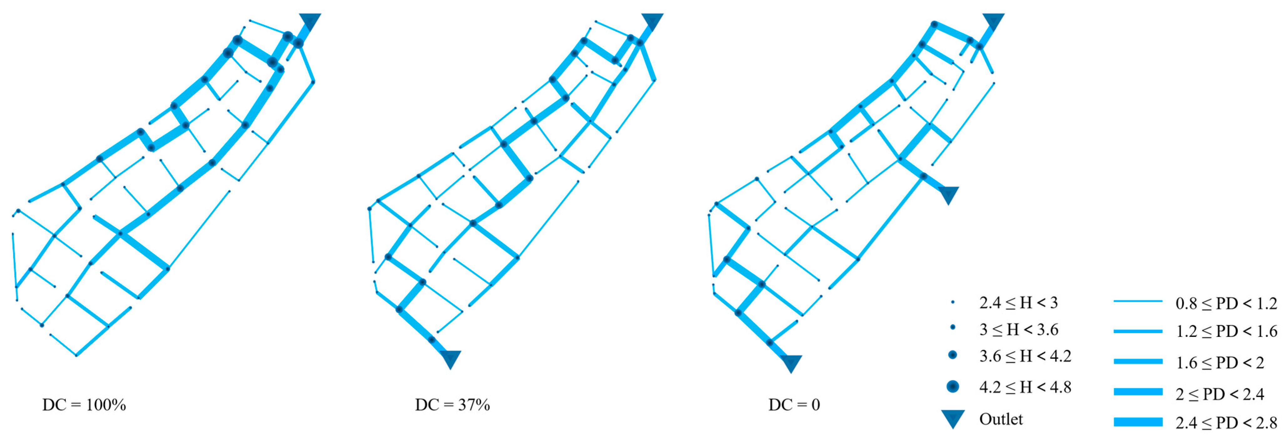
3.1. Layout of Drainage Systems with Different Degree of (De)centralization

The optimal system layouts for three different degrees of centralization, obtained through a search by the adaptive optimization engine, are depicted in Figure 9. Considering the stochastic nature of the GA’s operating mechanism, this study assumes that the process has converged if no better fitness solutions are found after exceeding 200 generations. The execution of this process, performed on a laptop equipped with an Intel Core i7, 3.00 GHz, 4-core CPU, and 16 GB of RAM, took a total of 28 h. Table 1 presents the specifications of the facility components and the construction costs for system layouts of varying degrees of decentralization. It is evident that the volume of flow carried by the main pipes within the (sub)systems decreases with the reduction in the DC, hence systems with a higher degree of centralization often require larger pipe diameters, resulting in a storage space that is nearly 40% greater for centralized solutions compared to decentralized ones. The design steps of the drainage network from upstream to downstream typically result in larger-scale systems having a deeper burial depth at the downstream end. However, a rebound in the maximum depth of manholes was observed in the system with a DC of 37%, which may be attributed to the algorithm’s selection of a smaller pipe diameter design to reduce construction costs under the premise of meeting reliability requirements. This selection is due to the inverse relationship between the pipe diameter and its burial slope. Consequently, the construction cost shows a significant downward trend as the DC decreases.

3.2. Candidate Addition (Replacement) Pipelines for Redundancy Intervention

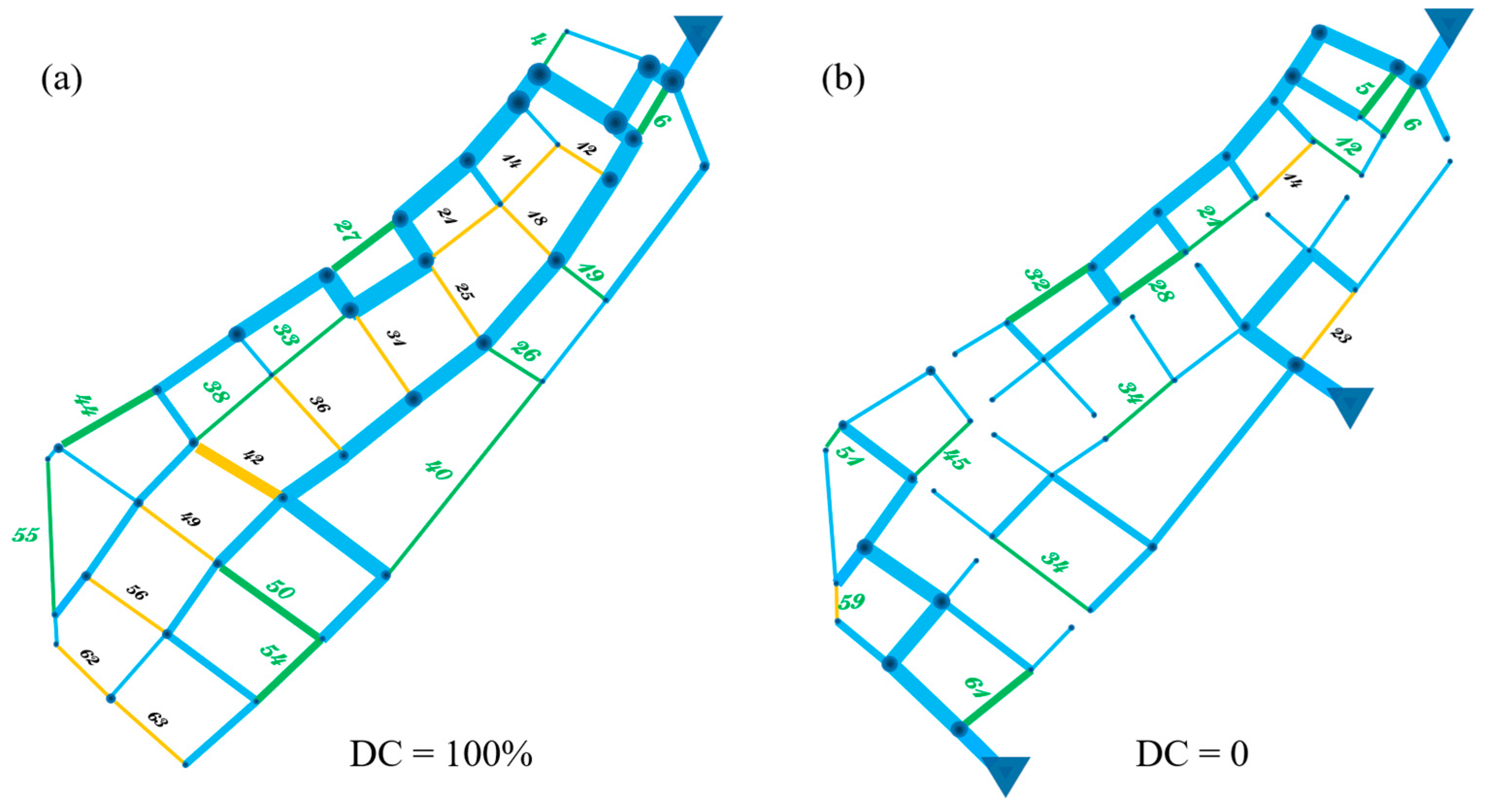
As described above, the number of permutations and combinations of intervention measures implemented at a certain intervention scale is a function of the number of candidate intervention measures. Considering the significant computational expense due to the rapid exponential growth, for both centralized and decentralized layouts, this study has selected 12 candidate pipes available for LI, following these selection criteria:
Each candidate pipe available for LI is implemented individually in the base layout scenario. They are then ranked in descending order based on the support they provide for reducing flood risk to the UDS under the action of the individual candidate pipe (as measured by the V T F indicator). To achieve a broader adaptability, candidate descending rankings with return periods of 10 a to 50 a are weighted. The top 12 addable pipes from both the centralized and decentralized layout lists are selected as the final list of candidates for implementation. Despite the same area having structural differences between its centralized and decentralized layouts due to the randomness of the generation algorithm and the inherent degree of decentralization, the number of candidate pipes available for the two intervention schemes is not the same. It is clear that the number of candidate pipes for LI is greater for the centralized layout than for the decentralized layout.
Due to the significant support in flood risk reduction provided by the top-ranked candidate addable pipes to the UDS, it follows that all loop combinations that exhibit good performance across all intervention scale scenarios also include these candidate pipes. In other words, the top-ranked candidate pipes play a primary role in the combinations of candidate pipes that have a positive supportive effect on the UDS. Specifically, the positions of candidate pipelines that can be added in a centralized layout and those that can be added in a decentralized layout in UDSs are shown in Figure 10.
The final candidate list of addable pipes for the LI in both layout distributions is presented in Table 2. It is noteworthy that, in the context of not reaching the maximum loop introduction scale, better flood risk reduction effects were achieved than the overall implementation. This may be due to the similar “antagonistic” mechanism between the pipeline at the end of the candidate list and other pipeline combinations in the entire UDS, which weakens the support of other redundant structures for UDS performance due to the overlap of high flow periods.
Similarly, the positions of candidate pipelines that can be replaced in a centralized layout and those that can be replaced in a decentralized layout in UDSs are shown in Figure 11. The final candidate list of addable pipes for loop construction in both layout distributions is detailed in Table 3.
As mentioned previously, the candidate pipe list for the hybrid scheme is an integrated list that combines the candidate pipes from two independent intervention schemes. Although the upper limit for the number of candidate addable (replaceable) pipes in the hybrid scheme is 24, considering the need to compare the results with the two independent schemes, the actual upper limit for the intervention scale is set to 12. The candidate pipe lists for the hybrid scheme under both layout distributions are shown in Table 4 and Table 5.
  • Mitigation effect of loop-introducing and pipe diameter enlarging
This study tested the hydraulic performance of the UDS under fully decentralized layouts (DC = 0) and centralized layouts (DC = 100%), ranging from scenarios with no redundancy interventions implemented (the basic scenario) to scenarios with full redundancy interventions. For the redundancy interventions involving the LI, there were 4096 scenarios for DC = 0 and 4096 scenarios for DC = 100%. Similarly, for the redundancy interventions involving the DE, there were also 4096 scenarios for DC = 0 and 4096 scenarios for DC = 100%. The study assessed the hydraulic performance under different rainfall characteristics, and the corresponding average node flooding duration for all solutions along the intervention scale-overflow volume curve are extracted, with scale 0 representing the basic scenario without any intervention implemented. Figure 12a–d correspond to the flood risk reduction effects of four types of solutions under the 10-year, 20-year, 30-year, and 50-year return periods for 3-h short-duration rainfall, respectively. These include LI in centralized layouts, DE in centralized layouts, LI in decentralized layouts, and DE in decentralized layouts. Figure 12e–h correspond to the intervention effects under 24 h long-duration rainfall characteristics. Each solution is represented by a data point in the figures, with the color indicating the level of t f ¯ reduction provided by the solution for the UDS at the corresponding intervention scale. Gray represents the average level, green indicates the reduction in t f ¯ above the average level, and red indicates a reduction below the average level. The darker the color, the higher the level of effectiveness.
It is clear that under any scenario, the decentralized layout provides significant flood risk reduction for the UDS, with this effect being particularly pronounced as the return period and rainfall duration increase. Specifically, during short-duration rainfall events, although the LI intervention offers strong competition for the centralized layout, the baseline level of the decentralized layout is already close to, or even surpassing, the best performance of the centralized layout with DE redundancy solutions. For long-duration rainfall scenarios, the decentralized layout achieves an overwhelming advantage. However, in the intervention mode of expanding pipe diameter, the decentralized layout cannot provide comprehensive flood risk reduction, showing a trade-off between V T F and t f , as evidenced by the red color of data points at the lower edge (lower V T F ). This result is also supported by the research of Sweetapple et al. [37].
Overall, the LI provides the best resilience enhancement for centralized layouts. In contrast, in decentralized layouts, due to the inherently high redundancy level (reflected in the greater number of water flow paths), this effect is greatly diluted. Therefore, compared to the significant difference in the growth rate of flood reduction reflected by the loop-introducing intervention and pipe diameter enlarging intervention in the centralized layout, the overflow mitigation effects of the two intervention measures in the decentralized layout are very similar. Under lower rainfall intensity, the intervention of expanding the pipe diameter provides better V T F improvement for the decentralized layout, and as rainfall intensity increases, the improvement shifts more towards t f ¯ reduction. Specifically, in Figure 12a, the decentralized layout implementing the DE achieves a greater increase in flood reduction than the LI. In the remaining scenarios for other return periods, although slightly weaker in flood alleviation effects, most of its solutions provide a considerable reduction in the t f ¯ for the UDS (represented by a darker shade of green in Figure 12). The adaptive tendencies of these different intervention measures may be attributed to the differences in storage space within the UDS for the two layout patterns. On one hand, for the subsystems of the decentralized layout, a larger pipe diameter provides a much greater increase in redundancy space than simply connecting two manholes to form a loop. In contrast, for the centralized layout, the increase in redundancy space provided by DE is relatively insignificant compared to its already substantial storage capacity. On the other hand, the benefit of effective flow distribution provided by looped pipelines is based on the system’s topological structure, which means that this improvement does not fluctuate significantly due to differences in storage space.
Additionally, under the scenario of short-term rainfall, there is a clear layering in the solution using a decentralized layout, and this phenomenon is particularly evident in the scenario of implementing pipe diameter enlarging intervention measures. This is because there are multiple subsystems at the level of the decentralized layout structure, and different subsystems implementing specific plans may bring significant efficiency changes to the entire system. The intervention of expanding the pipe diameter, due to its specific preference for improving spatial redundancy, has a more prominent impact on the decentralized system. However, considering that the data points located at the upper and lower edges of the image layering have different t f ¯ values, it is wise to choose a solution with a layered lower edge (shown in green) for improvement (their V T F is similar).
Interestingly, the decrease level of t f ¯ seems to exhibit the opposite trend in long and short duration rainfall scenarios. Specifically, under short-duration scenarios, as the rainfall return period increases, all four types of solution (LI in centralized layouts, DE in centralized layouts, LI in decentralized layouts, and DE in decentralized layouts) demonstrate superior levels of t f ¯ reduction, as indicated by the greater coverage of green in the sub-figure outlines. In contrast, under long-duration scenarios, the dominance of red coverage increases with the return period. This may be attributed to the local rainfall characteristics (refer to Figure 3), where the peak of short-duration rainfall occurs at the beginning of the rainfall event. At this time, there is no runoff within the system. The Bernoulli principle and the pressure difference between the inside and outside of the pipes allow redundant structures to discharge runoff more rapidly than conventional pipes when a large volume of runoff surges. As the return period increases, more rainfall enters, and more redundant interventions begin to take effect, thus showing good levels of t f ¯ reduction. For long-duration rainfall, the peak occurs in the middle to later stages, by which time there is already runoff within the system. The sudden influx of a large volume of runoff during the peak causes the system to operate at full pipeline capacity, reducing the transport capacity and thus having a negative impact on the improvement of t f ¯ . The greater the return period, the stronger the rainfall intensity during the peak period, and the more pronounced this effect becomes.
b.
The edges of hybrid mode
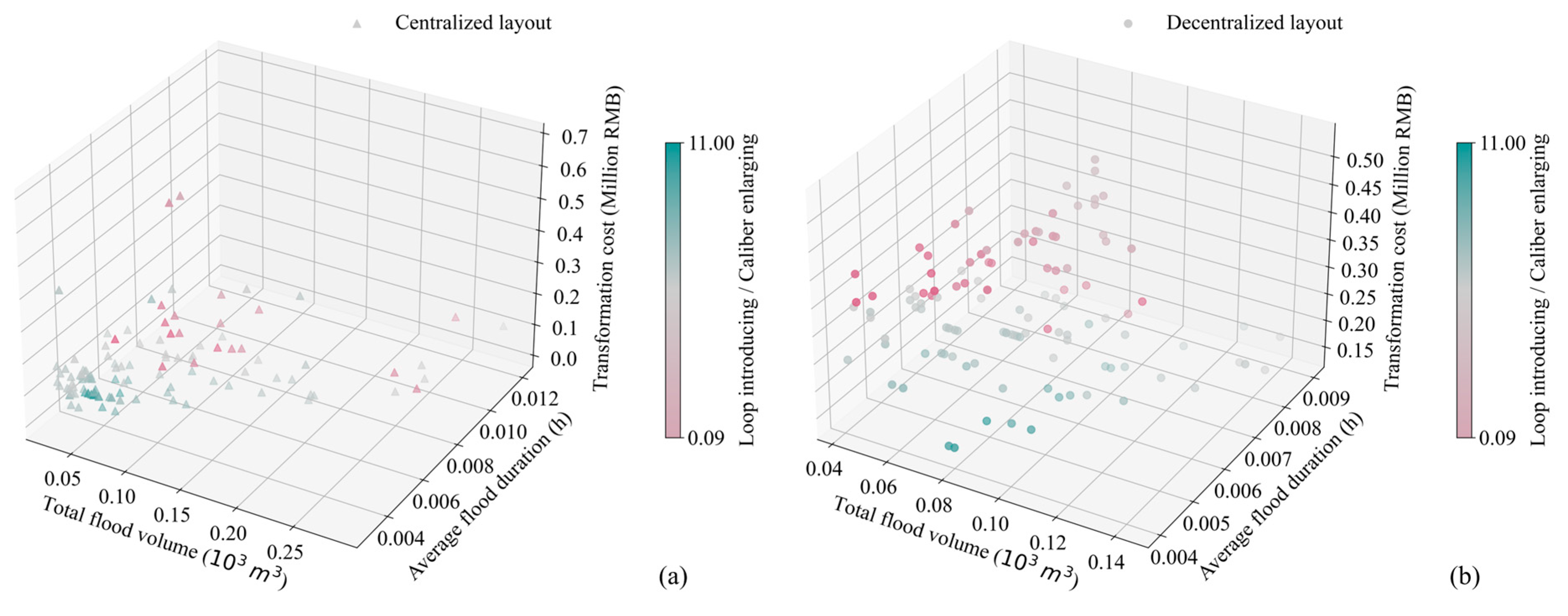
The proposed framework treats scale, location, and type of intervention as decision variables, and conducts an optimal configuration search for the application of hybrid intervention strategies on the UDS for both layout patterns under a short-duration rainfall scenario with a 10-year return period. To demonstrate the performance of the hybrid intervention, the upper limit of the intervention scale for the hybrid scheme is set to 12, which is consistent with the maximum implementation scale of the other two redundancy intervention modes. This ensures a comparison of intervention schemes with the same scale of implementation. The proposed framework obtained 10 approximate optimal solutions for each implementation scale ranging from 2 to 12, with over 50,000 intervention schemes assessed for each layout pattern. Additionally, 10 approximate optimal solutions at a given scale is non-dominated; however, there are dominance relationships between solutions of different scales. Figure 13 visually evaluates the performance of different solutions for the two layout patterns in the objective space by illustrating their positional relationships, where the color of the data points represents the proportion of the two intervention measures in the hybrid scheme (LI/DE). A green color indicates that the scale of LI exceeds that of DE, and a red color indicates the opposite.
In the objective space presented in Figure 13, the hybrid scheme provides significant flood risk reduction for both layout patterns of the UDS. Considering that the centralized layout has a higher baseline flood volume under the 10-year rainfall conditions but achieves a similar level of adaptability with the mixed redundancy intervention, the hybrid intervention scheme offers greater potential for flood risk reduction for the centralized UDS. This implies that the hybrid intervention can provide support for flood adaptation to most UDSs. The solutions in the lower left corner of the figure represent the ideal position for the existence of optimal solutions (minimizing all three objectives), indicating that the solutions obtained through the proposed framework offer the best combination of flood risk reduction and transformation cost. Moreover, for both layout patterns, the ideal solutions always have a higher proportion of LI, which corroborates the research findings of Yazdi et al. [20]. Although some solutions with a higher proportion of DE provide competitive reductions in V T F and t f ¯ for the UDS, these solutions are uneconomical. This is because the same length of candidate pipes used for pipe diameter enlarging intervention upgrades always requires the replacement with larger diameter pipes, which also implies a greater transformation expense.
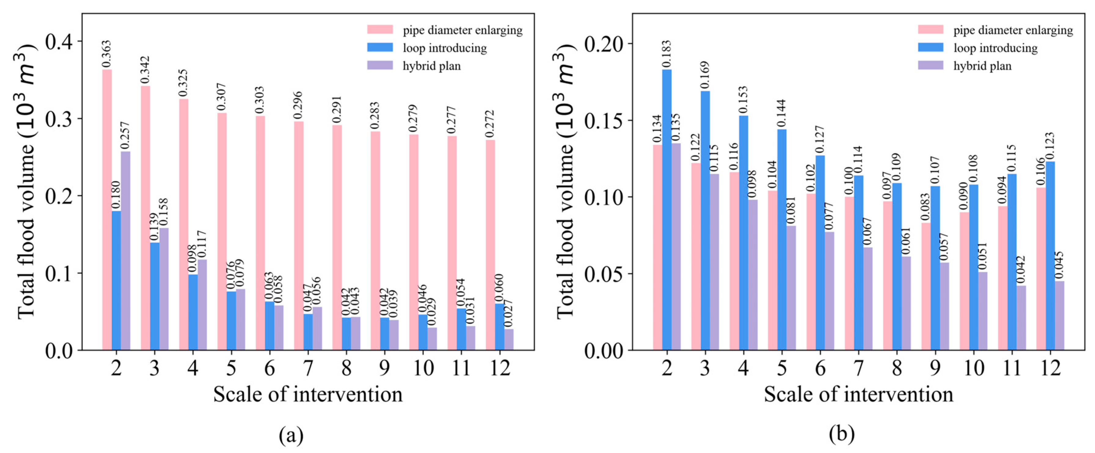
Figure 14 presents a comparison of the best solutions for V T F across different intervention modes as the scale of intervention increases, showing an overall downward trend in V T F with the rising intervention scale. As shown in Figure 14a, in the centralized layout, hybrid intervention schemes gradually take the lead at a scale of 6 and beyond, while in the decentralized layout, the hybrid intervention scheme achieves the minimum V T F across almost all intervention scales. Considering that SPEA2 is a probabilistic stochastic optimization method, the hybrid scheme configurations obtained by the proposed framework are approximate optimal solutions, whereas the V T F optimal solutions for the other two intervention modes are actual global optimal solutions obtained through global analysis. This implies that the implementation effect of the hybrid intervention is generally superior to the effects of the two schemes when implemented independently.
Furthermore, under the scenarios where the two single-effect redundancy interventions are implemented, there is a rebound in V T F as the intervention scale increases. However, this phenomenon is not pronounced under the scenario where the hybrid intervention is implemented. This is because excessive interventions lead to an overlap of peak runoff periods among components, resulting in a weakened growth rate or even a negative growth in the flood adaptation capacity of the UDS. Nevertheless, the two intervention measures provide distinct support for the UDS’s flood adaptation capabilities—effective flow distribution and flow capacity enhancement—and a specific hybrid pattern can leverage the advantages of both, thereby providing stronger flood risk reduction for the UDS. However, this advantage of the hybrid intervention is essentially manifested as a deferred (or extended) implementable intervention scale. In our study, as the hybrid intervention scale continues to expand (with a maximum limit of 24), the phenomenon of V T F rebounding with the increase in intervention scale still occurs. Therefore, it is necessary to implement any intervention method within the upper limit of the intervention scale.
Although the redundant intervention measures of specific solutions for the urban drainage system (UDS) offer significant reductions in flood risk, the expedited discharge of runoff may engender downstream flood hazards and the translocation of water accumulation sites [33]. Furthermore, within the context of future climate change uncertainties, purely structural mitigation interventions may exhibit limitations, and the integration with green stormwater infrastructure (GSI) has demonstrated efficacy [38,39]. Considering the flexibility of GSI [24]—characterized by the intrinsic capacity of the system to reconfigure and adjust under diverse (fluctuating) load conditions to sustain an acceptable performance level—coupled with the two types of redundant intervention schemes executed in this research, it is anticipated that the disparity in flood resilience between centralized and decentralized UDS layouts will be made up. This will broaden the applicability of redundant intervention measures, particularly in scenarios where existing UDS predominantly feature a centralized layout.

4. Conclusions

Against the backdrop of accelerated urbanization and increasing climate uncertainty, urban water management is on the cusp of a paradigm shift. This study proposes a structural upgrading and optimization method for the grey infrastructure of the UDS from the perspective of resilience. Through extensive scenario analysis, the impact of introducing redundant interventions, such as loops introducing and expanding pipe diameters on the hydraulic performance of urban drainage systems, is explored. The results indicate the following:
  • For intervention measures involving the replacement or upgrading of components within the drainage network, not all intervention combinations provide positive support to the performance of the UDS. The interplay among different solutions results in varying UDS performance, indicating that precise deployment of grey infrastructure is crucial for urban water management practices.
  • The structural variations in UDS, arising from differences in degree of centralization, confer distinct improvement preferences to the two categories of redundant intervention measures. The strategy of loop introduction offers enhanced resilience and significant, robust improvements for centralized UDS layouts across almost all rainfall scenarios. Conversely, for decentralized UDS layouts, the hydraulic improvements provided by both intervention measures are very similar.
  • Considering that most built-up urban areas (watersheds) feature centralized UDS layouts, the transformation to decentralized layouts may involve extensive pipe redirection projects due to hydraulic constraints, including changes in pipe diameter, slope, and burial depth, although decentralized layouts can significantly alleviate V_TF (total overflow volume). Constructing loop redundancy structures is clearly a more economical choice. For newly planned construction sites, decentralized layouts are a novel and competitive option, depending on feasibility. For watersheds that have already adopted decentralized layouts, the replacement of key pipe diameters may further enhance their performance.
  • Compared to the two intervention modes that act independently, the hybrid scheme provides the UDS with flood risk adaptation support that combines effective runoff distribution and increased flow capacity, thus promising optimal intervention outcomes. However, as the scale of intervention increases, the hybrid intervention may also encounter conflicts in the effectiveness of the effects between components. It is necessary to determine an appropriate upper limit for the scale of intervention.
The current study primarily relies on extensive virtual scenario analysis and has not conducted tests on real-world cases; therefore, the analysis results regarding the performance impact provided by redundant intervention measures do not possess complete generalizability for application. Additionally, the improvement in adaptability brought about solely by redundant intervention measures is not comprehensive. In future work, we will further integrate GSI and real-time control (RTC) methods to expect a more systematically hydraulic performance enhancement for UDS.

Author Contributions

Conceptualization, Y.Z. and E.W.; Formal analysis, Y.Z.; Methodology, Y.Z. and Y.G.; Resources, Y.G.; Software, Y.Z.; Supervision, E.W. and Y.G.; Visualization, Y.Z.; Writing—original draft, Y.Z.; Writing—review & editing, E.W. and Y.G. All authors have read and agreed to the published version of the manuscript.

Funding

This research was funded by National Key R&D Program of China (Grand No. 2022YFC3800500) and the Project of Construction and Support for High-Level Innovative Teams of Beijing Municipal-Institutions (BPHR20220108) and the BUCEA Doctor Graduate Scientific Research Ability Improvement Project (No. DG2022012).

Data Availability Statement

The satellite image data in this study comes from Google Maps, the rainfall data presented in this study are available on request from the corresponding author.

Conflicts of Interest

The authors of this study have no known competitive economic interests or personal relationships.

References

  1. Miller, J.D.; Hutchins, M. The impacts of urbanisation and climate change on urban flooding and urban water quality: A review of the evidence concerning the United Kingdom. J. Hydrol. Reg. Stud. 2017, 12, 345–362. [Google Scholar] [CrossRef]
  2. Lu, M.; Yu, Z.; Hua, J.; Kang, C.; Lin, Z. Spatial dependence of floods shaped by extreme rainfall under the influence of urbanization. Sci. Total Environ. 2023, 857, 159134. [Google Scholar] [CrossRef] [PubMed]
  3. Dharmarathne, G.; Waduge, A.O.; Bogahawaththa, M.; Rathnayake, U.; Meddage, D.P.P. Adapting cities to the surge: A comprehensive review of climate-induced urban flooding. Results Eng. 2024, 22, 102123. [Google Scholar] [CrossRef]
  4. Tang, Z.; Wang, P.; Li, Y.; Sheng, Y.; Wang, B.; Popovych, N.; Hu, T. Contributions of climate change and urbanization to urban flood hazard changes in China’s 293 major cities since 1980. J. Environ. Manag. 2024, 353, 120113. [Google Scholar] [CrossRef] [PubMed]
  5. Jiang, Y.; Zevenbergen, C.; Ma, Y. Urban pluvial flooding and stormwater management: A contemporary review of China’s challenges and “sponge cities” strategy. Environ. Sci. Policy 2018, 80, 132–143. [Google Scholar] [CrossRef]
  6. Zhou, Q.; Leng, G.; Su, J.; Ren, Y. Comparison of urbanization and climate change impacts on urban flood volumes: Importance of urban planning and drainage adaptation. Sci. Total Environ. 2019, 658, 24–33. [Google Scholar] [CrossRef] [PubMed]
  7. Tellman, B.; Sullivan, J.A.; Kuhn, C.; Kettner, A.J.; Doyle, C.S.; Brakenridge, G.R.; Erickson, T.A.; Slayback, D.A. Satellite imaging reveals increased proportion of population exposed to floods. Nature 2021, 596, 80–86. [Google Scholar] [CrossRef] [PubMed]
  8. Jovanovic, T.; Hale, R.L.; Gironás, J.; Mejia, A. Hydrological Functioning of an Evolving Urban Stormwater Network. Water Resour. Res. 2019, 55, 6517–6533. [Google Scholar] [CrossRef]
  9. Eggimann, S.; Truffer, B.; Maurer, M. To connect or not to connect? Modelling the optimal degree of centralisation for wastewater infrastructures. Water Res. 2015, 84, 218–231. [Google Scholar] [CrossRef]
  10. Fortunato, A.; Oliveri, E.; Mazzola, M.R. Selection of the Optimal Design Rainfall Return Period of Urban Drainage Systems. Procedia Eng. 2014, 89, 742–749. [Google Scholar] [CrossRef]
  11. Bieker, S.; Cornel, P.; Wagner, M. Semicentralised supply and treatment systems: Integrated infrastructure solutions for fast growing urban areas. Water Sci. Technol. 2010, 61, 2905–2913. [Google Scholar] [CrossRef]
  12. Obando, G.; Poveda, J.I.; Quijano, N. Replicator dynamics under perturbations and time delays. Math. Control. Signals Syst. 2016, 28, 20. [Google Scholar] [CrossRef]
  13. Bakhshipour, A.E.; Bakhshizadeh, M.; Dittmer, U.; Haghighi, A.; Nowak, W. Hanging Gardens Algorithm to Generate Decentralized Layouts for the Optimization of Urban Drainage Systems. J. Water Resour. Plan. Manag. 2019, 145, 04019034. [Google Scholar] [CrossRef]
  14. Hesarkazzazi, S.; Hajibabaei, M.; Bakhshipour, A.E.; Dittmer, U.; Haghighi, A.; Sitzenfrei, R. Generation of optimal (de)centralized layouts for urban drainage systems: A graph-theory-based combinatorial multi-objective optimization framework. Sustain. Cities Soc. 2022, 81, 103827. [Google Scholar] [CrossRef]
  15. Wang, M.; Chen, B.; Zhang, D.; Yuan, H.; Rao, Q.; Zhou, S.; Li, J.; Wang, W.; Tan, S.K. Comparative life cycle assessment and life cycle cost analysis of centralized and decentralized urban drainage systems: A case study in Zhujiang New Town, Guangzhou, China. J. Clean. Prod. 2023, 426, 139173. [Google Scholar] [CrossRef]
  16. Mugume, S.N.; Gomez, D.E.; Fu, G.; Farmani, R.; Butler, D. A global analysis approach for investigating structural resilience in urban drainage systems. Water Res. 2015, 81, 15–26. [Google Scholar] [CrossRef] [PubMed]
  17. Ahern, J. From fail-safe to safe-to-fail: Sustainability and resilience in the new urban world. Landsc. Urban Plan. 2011, 100, 341–343. [Google Scholar] [CrossRef]
  18. Haghbin, S.; Mahjouri, N. Quantifying and improving flood resilience of urban drainage systems based on socio-ecological criteria. J. Environ. Manag. 2023, 339, 117799. [Google Scholar] [CrossRef] [PubMed]
  19. Di Nardo, A.; Di Natale, M.; Giudicianni, C.; Musmarra, D.; Varela, J.M.R.; Santonastaso, G.F.; Simone, A.; Tzatchkov, V. Redundancy Features of Water Distribution Systems. Procedia Eng. 2017, 186, 412–419. [Google Scholar] [CrossRef]
  20. Yazdi, J. Improving Urban Drainage Systems Resiliency Against Unexpected Blockages: A Probabilistic Approach. Water Resour. Manag. 2018, 32, 4561–4573. [Google Scholar] [CrossRef]
  21. Lu, J.; Liu, J.; Fu, X.; Wang, J. Stormwater hydrographs simulated for different structures of urban drainage network: Dendritic and looped sewer networks. Urban Water J. 2021, 18, 522–529. [Google Scholar] [CrossRef]
  22. Lu, J.; Liu, J.; Yu, Y.; Liu, C.; Su, X. Network Structure Optimization Method for Urban Drainage Systems Considering Pipeline Redundancies. Int. J. Disaster Risk Sci. 2022, 13, 793–809. [Google Scholar] [CrossRef]
  23. Reyes-Silva, J.D.; Bangura, E.; Helm, B.; Benisch, J.; Krebs, P. The Role of Sewer Network Structure on the Occurrence and Magnitude of Combined Sewer Overflows (CSOs). Water 2020, 12, 2675. [Google Scholar] [CrossRef]
  24. Hesarkazzazi, S.; Bakhshipour, A.E.; Hajibabaei, M.; Dittmer, U.; Haghighi, A.; Sitzenfrei, R. Battle of centralized and decentralized urban stormwater networks: From redundancy perspective. Water Res. 2022, 222, 118910. [Google Scholar] [CrossRef]
  25. Kwon, S.H.; Jung, D.; Kim, J.H. Optimal Layout and Pipe Sizing of Urban Drainage Networks to Improve Robustness and Rapidity. J. Water Resour. Plan. Manag. 2021, 147, 06021003. [Google Scholar] [CrossRef]
  26. Alfaisal, F.M.; Mays, L.W. Optimization Models for Layout and Pipe Design for Storm Sewer Systems. Water Resour. Manag. 2021, 35, 4841–4854. [Google Scholar] [CrossRef]
  27. Ogidan, O.; Giacomoni, M. Multiobjective Genetic Optimization Approach to Identify Pipe Segment Replacements and Inline Storages to Reduce Sanitary Sewer Overflows. Water Resour. Manag. 2016, 30, 3707–3722. [Google Scholar] [CrossRef]
  28. Hesarkazzazi, S.; Hajibabaei, M.; Diao, K.; Sitzenfrei, R. Implication of Different Pipe-Sizing Strategies for the Resilience of Stormwater Networks. In Proceedings of the World Environmental and Water Resources Congress 2021, virtual, 7–11 June 2021; pp. 244–252. [Google Scholar]
  29. Liu, Y.; Zhao, W.; Wei, Y.; Sebastian, F.S.M.; Wang, M. Urban waterlogging control: A novel method to urban drainage pipes reconstruction, systematic and automated. J. Clean. Prod. 2023, 418, 137950. [Google Scholar] [CrossRef]
  30. Mair, M.; Zischg, J.; Rauch, W.; Sitzenfrei, R. Where to Find Water Pipes and Sewers?—On the Correlation of Infrastructure Networks in the Urban Environment. Water 2017, 9, 146. [Google Scholar] [CrossRef]
  31. Haghighi, A. Loop-by-Loop Cutting Algorithm to Generate Layouts for Urban Drainage Systems. J. Water Resour. Plan. Manag. 2013, 139, 693–703. [Google Scholar] [CrossRef]
  32. Katoch, S.; Chauhan, S.S.; Kumar, V. A review on genetic algorithm: Past, present, and future. Multimed. Tools Appl. 2021, 80, 8091–8126. [Google Scholar] [CrossRef] [PubMed]
  33. Li, S.; Leitão, J.P.; Wang, Z.; Bach, P.M. A drainage network-based impact matrix to support targeted blue-green-grey stormwater management solutions. Sci. Total Environ. 2024, 912, 168623. [Google Scholar] [CrossRef] [PubMed]
  34. Zitzler, E.; Laumanns, M.; Thiele, L. SPEA2: Improving the Strength Pareto Evolutionary Algorithm; ETH Zurich, Computer Engineering and Networks Laboratory: Zurich, Switzerland, 2001. [Google Scholar]
  35. Deb, K.; Pratap, A.; Agarwal, S.; Meyarivan, T. A fast and elitist multiobjective genetic algorithm: NSGA-II. IEEE Trans. Evol. Comput. 2002, 6, 182–197. [Google Scholar] [CrossRef]
  36. Wang, M.; Fang, Y.; Sweetapple, C. Assessing flood resilience of urban drainage system based on a ‘do-nothing’ benchmark. J. Environ. Manag. 2021, 288, 112472. [Google Scholar] [CrossRef] [PubMed]
  37. Sweetapple, C.; Fu, G.; Farmani, R.; Meng, F.; Ward, S.; Butler, D. Attribute-based intervention development for increasing resilience of urban drainage systems. Water Sci. Technol. 2018, 77, 1757–1764. [Google Scholar] [CrossRef] [PubMed]
  38. Moon, H.-T.; Kim, J.-S.; Chen, J.; Yoon, S.-K.; Moon, Y.-I. Mitigating urban flood Hazards: Hybrid strategy of structural measures. Int. J. Disaster Risk Reduct. 2024, 108, 104542. [Google Scholar] [CrossRef]
  39. Yin, D.; Zhang, X.; Cheng, Y.; Jia, H.; Jia, Q.; Yang, Y. Can flood resilience of green-grey-blue system cope with future uncertainty? Water Res. 2023, 242, 120315. [Google Scholar] [CrossRef]
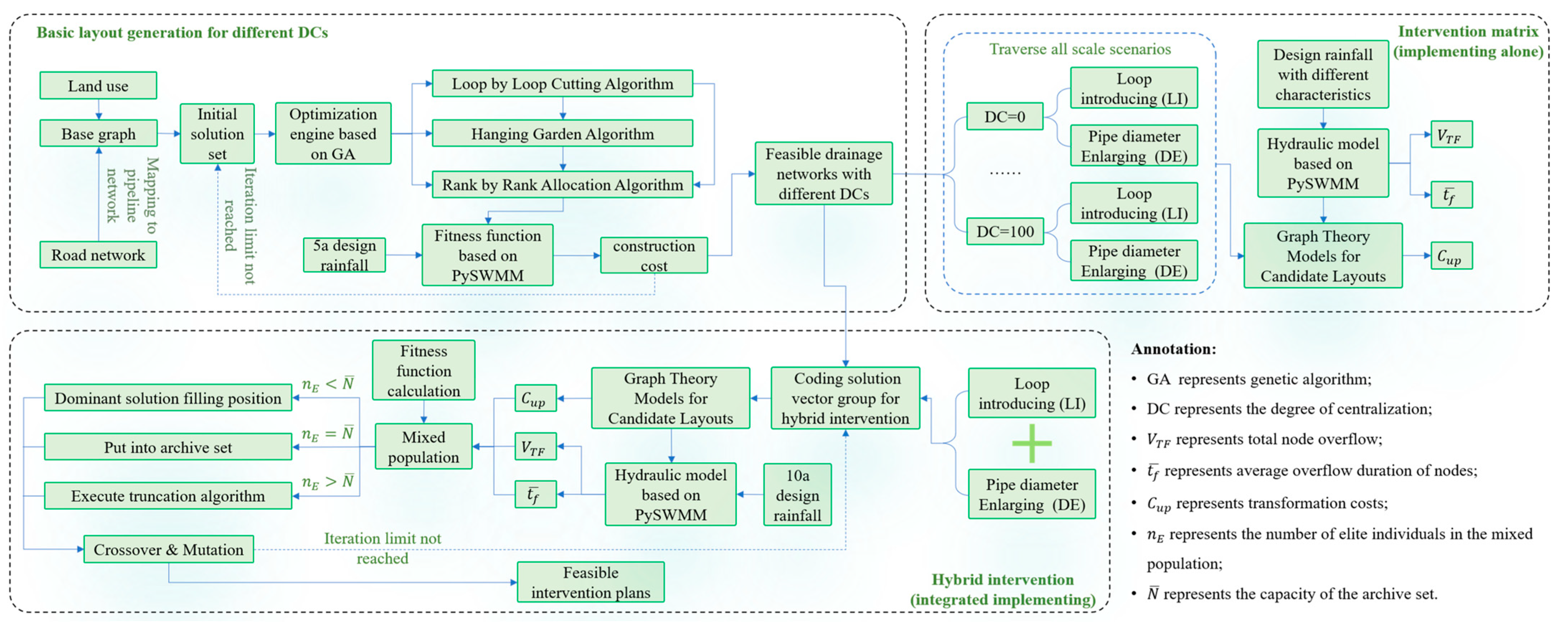
Figure 1. Logic flowchart of this study.
Water 16 01696 g001
Figure 2. Study area and base graph.
Water 16 01696 g002
Figure 3. Local design rainfall in the study area: (a) short duration precipitation; (b) long duration precipitation.
Water 16 01696 g003
Figure 4. Layout generation process.
Water 16 01696 g004
Figure 5. Overview of the proposed layout generation framework.
Water 16 01696 g005
Figure 6. Pedagogical example of loop placement. Different colors are used to indicate that the pipeline belongs to different subsystems, and arrows are used to indicate the direction of water flow inside the pipeline.
Water 16 01696 g006
Figure 7. Pedagogical example of global hydraulic analysis. The yellow pipeline is used to express the different implementation scenarios of the intervention measures in the example.
Water 16 01696 g007
Figure 8. Logic framework flowchart of hybrid optimization scheme.
Water 16 01696 g008
Figure 9. Layout optimization results under different DCs.
Water 16 01696 g009
Figure 10. Schematic diagram of candidate pipelines for loop-introducing analysis in (a) centralized layout (b) decentralized layout. Green pipelines represent candidate pipelines for loop-introducing, the yellow pipeline represents a candidate pipeline that was not selected due to insufficient hydraulic improvement provided for UDS.
Water 16 01696 g010
Figure 11. Schematic diagram of candidate pipelines for pipe diameter enlarging in (a) centralized layout (b) decentralized layout. Red pipelines represent candidate pipelines for diameter enlarging.
Water 16 01696 g011
Figure 12. Flood mitigation performance of system implementation of redundant interventions under different rainfall characteristics scenarios: (a) 10 a–3 h; (b) 20 a–3 h; (c) 30 a–3 h; (d) 50 a–3 h; (e) 10 a–24 h; (f) 20 a–24 h; (g) 30 a–24 h; (h) 50 a–24 h.
Water 16 01696 g012
Figure 13. The distribution of alternative solutions in the target space: (a) centralized layout; (b) decentralized layout.
Water 16 01696 g013
Figure 14. The relationship between flood volume and intervention scale for the best solution of different intervention modes (under 3 h rainfall with 10 a return period): (a) centralized layout; (b) decentralized layout.
Water 16 01696 g014
Table 1. Facility specifications and construction costs for optimizing the layout of gray infrastructure with different degrees of decentralization.
Degree of Centralization (%)Total Length of Pipes (m)Average Diameter (m)Maximum Diameter (m)Maximum Depth of Manholes (m)Cost (10 Million RMB)Storage Capacity (m3)
10022,956.961.662.64.512.2851,503.50
3722,965.781.462.44.721.5740,446.29
022,999.941.422.23.971.4336,808.73
Table 2. List of candidate pipelines for loop-introducing.
Degree of Centralization (%)Candidate Addition Pipelines for Loop-IntroducingEffect Proportion
1002665040195427443833554112.14%
05034532628215951451261106.80%
Table 3. List of candidate pipelines for pipe diameter enlarging.
Degree of Centralization (%)Candidate Replacement Pipelines for Pipe Diameter Enlarging
100415363376046586261325131
0334640374439424149294852
Table 4. List of candidate pipelines for hybrid intervention (DC = 100%).
Intervention ModeCandidate Addition (Replacement) Pipelines
Loop-introducing2665040195427443833554
Caliber enlarging415363376046586261325131
Table 5. List of candidate pipelines for hybrid intervention (DC = 0).
Intervention ModeCandidate Addition (Replacement) Pipelines
Loop-introducing5034532628215951451261
Caliber enlarging334640374439424149294852
Disclaimer/Publisher’s Note: The statements, opinions and data contained in all publications are solely those of the individual author(s) and contributor(s) and not of MDPI and/or the editor(s). MDPI and/or the editor(s) disclaim responsibility for any injury to people or property resulting from any ideas, methods, instructions or products referred to in the content.