Abstract
With the rapid advancement of ecological civilization construction, prioritizing green stormwater infrastructure to address urban stormwater management issues has become an important strategy for ecological priority and green development in sustainable urban development. Green stormwater infrastructure, as a major facility in the construction of sponge cities, can reduce the generation and external discharge of runoff and play a purification role. However, there are various types of green stormwater infrastructure, each with different control effects and applicable conditions. Therefore, to facilitate the planning, design, acceptance, assessment, and monitoring evaluation of sponge city green stormwater infrastructure, this study proposes the “sponge equivalent” method. By comparing the control effects of different facilities with bioretention facilities, the method standardizes the effects, making them easier to understand and apply. Taking a typical area of Beijing and its urban roads as examples, the study analyzed and applied planning and design control strategies. The results show that for a residential area of 1 km2, to achieve the annual runoff total control rate target of 85%, the method of converting runoff volume control equivalents, using bioretention pools as a benchmark, allows for the calculation of various combinations of areas of different types of green stormwater infrastructure, such as sunken green spaces, permeable paving bricks, green roofs, and water storage tanks. This optimizes the planning index of Beijing, which mandates stormwater detention facilities for new projects with a hardened surface area of 2000 m2 or more. The sponge equivalent method can optimize the planning and design control strategy of green stormwater infrastructure, allowing for rapid assessment and application of the design scale of green stormwater infrastructure in areas during the planning and design stage, providing theoretical and technical support for ecological and green urban stormwater management. The application of this research method helps promote green development and ecological priority in urban sustainable development strategies, and the conclusions provide valuable references for decision-makers and practitioners in related fields.
1. Introduction
As the process of urbanization accelerates globally, urban stormwater management has become a crucial and pressing task. With the deepening of urbanization, significant changes in land use patterns have occurred, especially the increase in impervious surfaces, leading to a substantial increase in urban surface runoff. This poses a significant challenge to the sustainable use of urban water resources and the stability of urban ecosystems [1]. Moreover, traditional urbanization models often overlook the importance of harmonious coexistence with the natural environment, exceeding the ecological carrying capacity and disrupting ecological balance [2]. This pattern is particularly evident in urban stormwater management, leading to a range of disadvantages. The primary issues include the widespread application of surface hardening and centralized drainage systems, both of which limit natural stormwater infiltration and groundwater replenishment, exacerbating urban flood disasters and water scarcity issues. Furthermore, this model typically fails to effectively consider stormwater as a usable resource, instead treating it as waste that needs to be rapidly eliminated, resulting in water cycle imbalance and inefficient water resource utilization. Huang et al. [3] reviewed the construction, management, and maintenance status of waterway networks under China’s traditional urbanization model, which largely employs combined sewer overflows, along with the high risks of sewer overflow and consequent health hazards. Therefore, effective management and resource utilization of stormwater becomes particularly crucial in the urbanization process [4]. Sponge cities, as a novel urban stormwater management strategy, aim to protect the ecological environment and spatial structure by adopting low-impact environmental development and controlling development intensity, striving to maintain the pre-development status of surface runoff.
Green infrastructure (GI) is an effective strategy for addressing urban stormwater challenges, with its concept gradually evolving and maturing from the late 20th century to the early 21st century. The design of Central Park in 19th-century New York, USA, stands as one of the early significant examples of leveraging the natural environment to enhance urban living quality, offering valuable insights for the subsequent development of green infrastructure [5]. The Environmental Protection Agency (EPA) emphasizes that GI relies on or simulates natural ecosystems to ensure environmental quality and provide efficient services [6]. Maryland further defined GI to include both natural and artificial systems, focusing on land, climate, and water resource management [7]. In 2006, the American Planning Association defined GI as a network of natural areas effectively controlling stormwater runoff, playing a key role in alleviating floods and pollution, and in urban hydrological cycles and stormwater control [8]. Seattle Public Utilities introduced green stormwater infrastructure (GSI), including measures such as rain gardens, wetlands, and green roofs [9]. Traditional gray infrastructure increases urban surface runoff and reduces infiltration rates, leading to urban waterlogging and water environment pollution [10]. Green stormwater infrastructure manages stormwater through decentralized measures including infiltration, storage, regulation, transmission, and purification, effectively addressing urban runoff and pollutant emissions, promoting harmonious coexistence between cities and nature, and bringing environmental, economic, and social benefits [11,12]. Green stormwater infrastructure is an innovation in traditional urban stormwater management, aiming to comprehensively address environmental, water resource, aquatic ecosystem, and water security issues while promoting harmonious coexistence between humans and nature [13]. This study emphasizes green stormwater infrastructure as various green ecological facilities used in stormwater management, implementing multi-objective control of stormwater at every stage—generation, concentration, conveyance, and discharge—to reduce excessive stormwater runoff, decrease pollution from surface runoff, and enhance the comprehensive utilization efficiency of urban stormwater [14,15].
In China, green stormwater infrastructure has become a major component of sponge city construction [16]. The concept of sponge cities in China not only includes the multi-objective control system of stormwater system planning and design but also draws on ancient Chinese stormwater management concepts and practices [17,18]. Ancient Chinese stormwater management strategies and technologies, particularly those articulated in the classical text “Yuan Ye”, offer valuable historical experiences and insights for contemporary urban stormwater management. The methods in “Yuan Ye” emphasize the importance of harmonious coexistence with nature, including efficient water body layouts, water source protection, and techniques for natural stormwater infiltration and storage. This ancient wisdom holds significant reference value for guiding modern urban planning and sustainable development, especially in the utilization and management of stormwater resources. By integrating these traditional approaches with modern technologies, we can more effectively address the challenges of water resource management in the urbanization process, thereby promoting the construction of an ecological civilization [19]. Che et al. [20] elucidated the connotation of sponge cities, constructing comprehensive goals and analyzing relationships between various sub-goals. Li et al. [21] proposed a multi-objective control system for stormwater system planning and design. Wang et al. [22] analyzed the relationship between urban waterlogging prevention and control and the major–minor drainage systems in China. Liu et al. [23] analyzed multi-scale urban green stormwater infrastructure planning and design. However, despite significant progress in the research and application of green stormwater infrastructure, challenges and problems still exist in practical urban planning and design [24,25]. These include mismatches between the scale of green stormwater infrastructure and actual goals, overly simplistic or unreasonable choices of combined facilities, and the lack of simplified and effective evaluation methods in sponge city assessments. Thus, determining how to reasonably plan, design, and lay out green stormwater infrastructure and quickly evaluate its effectiveness is an urgent issue in the planning, construction, and evaluation of sponge cities.
This study introduces a novel “Sponge Equivalent” method, aimed at simplifying and standardizing the assessment and planning process of green stormwater infrastructure (GSI). This approach converts the stormwater management efficacy of various GSI facilities into a standardized metric based on unit area runoff volume control, providing an intuitive and effective assessment and control framework for GSI planning in urban design. The study initially explores the challenges faced by ecological civilization construction in urban stormwater management and reviews research progress in related fields, particularly regarding the “Sponge City” concept and its application in green stormwater infrastructure. Subsequently, it details the theoretical foundation and implementation steps of the “Sponge Equivalent” method, demonstrating its practical application through a case study of a typical district in Beijing and its road network. The research results intricately showcase the calculation and optimization of controlled runoff volume, and the scientific significance and potential impacts of these findings are delved deeply into in the discussion section. Finally, the conclusion and recommendation section summarizes the main findings and offers specific suggestions for urban planners and practitioners, while also projecting future research directions.
2. Materials and Methods
2.1. Urban Typical Area Green Stormwater Infrastructure Planning and Design Control Strategies
2.1.1. Introduction and Analysis Method of Sponge Equivalency Concept
“Sponge equivalent” refers to a metric used in various green stormwater infrastructure systems, where the control effects of a specified unit amount of facilities (runoff volume, peak runoff, runoff pollution, etc.) serve as a basis for comparison. Other facilities’ control effects are then compared to this standard, with the goal of achieving a comparable magnitude of effect. For example, in source control facilities, bioretention measures are the most representative and commonly used facilities. Using bioretention facilities as a research unit, the sponge equivalent of other facilities is calculated by converting the control capabilities of those facilities (e.g., runoff volume, total runoff pollution) to a ratio in comparison to the bioretention facilities, which standardizes the control effects across different facilities [26]. The reason for using the “sponge equivalent” measurement is to construct a reasonable framework that allows for the quantification of the control objectives achieved by typical green stormwater infrastructure. With the concept of sponge equivalents, it is possible to refine the classification according to the different functions of stormwater runoff control facilities, such as runoff volume control equivalents and runoff pollution control equivalents. This proposes a new method for design and evaluation, making the method and conclusions more intuitive, easier to understand, and more applicable.
In the construction of sponge cities, control of runoff volume is central, and the core control indicator of the annual total runoff control rate is also based on runoff volume control [27]. Volume control will also indirectly reduce total runoff pollution and peak runoff flow rate [28]. However, the corresponding equivalent calculation will be more complex. For easier understanding, this study analyzes the example of runoff volume control equivalents.
2.1.2. Conversion Relationships of Sponge Equivalents for Typical Green Stormwater Infrastructure
The sponge equivalent for green stormwater infrastructure is applicable not only to source reduction facilities but also to the entire process of stormwater control systems, including process control and terminal regulation facilities. This study introduces the conversion and application of sponge equivalents using typical green stormwater infrastructure as an example, selecting bioretention facilities as the reference benchmark to convert the sponge equivalents of other facilities. In the planning and construction of green stormwater infrastructure, when the goal is total runoff control, the effective storage volume of green stormwater infrastructure required per unit catchment area is calculated, and the annual total runoff control rate target is accounted for. The runoff volume control equivalent is primarily converted using the volume method. The conversion of the runoff volume control equivalent is carried out in four typical structural configurations, taking the Beijing area as an example. According to the annual total runoff control rate target of 85%, the corresponding design rainfall is 33.6 mm. To achieve this target, corresponding stormwater source control measures are taken. The main factors related to runoff volume control are the effective storage volume and infiltration amount of the facilities. Calculations are performed under typical conditions set by experts and engineering experience, using bioretention facilities as the equivalent to convert other facilities. By applying the concept of sponge equivalents in this way, urban planners and engineers are able to standardize and compare the performance of diverse green stormwater infrastructure, optimizing the stormwater management system to meet sustainability and resilience goals.
Taking the calculation of the scale of runoff volume control for a unit area of sunken green space as an example, and using the volume of runoff volume control for a unit area of bioretention facilities as a benchmark, this passage explores and calculates the runoff volume controlled by other facilities under the premise of a typical construction. If the control scale of runoff volume for a unit area of bioretention facilities is approximately 0.62 m3, and the control scale of runoff volume for a unit area of sunken green space is approximately 0.28 m3, then the runoff volume control volume for 1 m2 of sunken green space is equivalent to the runoff volume control volume for 0.44 m2 of bioretention implementation. In this case, the runoff volume control equivalent value for the sunken green space is 0.44. In fact, the runoff volume control equivalent can also be expressed in other ways, such as the area required per unit runoff volume for each facility (m2/m3) or the runoff volume that can be controlled per unit area of the facility (m3/m2), as shown in Table 1, Table 2, Table 3 and Table 4. This method simplifies the comparison and calculation of different green stormwater infrastructure (GSI) types, making planning and design more efficient. Table 1 and Table 2 primarily provide the conversion relationships for runoff volume control equivalencies among other GSI types under typical construction assumptions for typical infiltration-technology-based GSI. Table 3 mainly presents the conversion relationships for runoff volume control equivalencies among other GSI types under typical construction assumptions for typical storage-technology-based GSI. Table 4 primarily details the conversion relationships for runoff volume control equivalencies among other GSI types under typical construction assumptions for GSI based on typical regulation technology, transfer technology, and pollutant interception and purification technology. This method simplifies the comparison and calculation of different types of green stormwater infrastructure, making planning and design more efficient. The conversion method of volume equivalents is crucial for optimizing the design of green stormwater infrastructure. By uniformly converting different types of infrastructure, such as permeable technologies, storage techniques, regulation methods, conveyance systems, and pollution interception and purification technologies, planners and designers can effectively determine the most efficient and suitable combination of facilities for a given area.

Table 1.
Conversion Relationships for Equivalent Runoff Volume Control between Typical Facilities of Four Infiltration Techniques and Bioretention Facilities.
Table 2.
Conversion Relationships for Runoff Volume Control Equivalents in Typical Facilities of Five Infiltration Techniques.
Table 3.
Conversion Relationships for Equivalent Runoff Volume Control between Typical Facilities of Four Storage Techniques and Bioretention Facilities.
Table 4.
Conversion relationship for equivalent runoff volume control in typical facilities using regulation techniques.
When implementing control strategies for the planning and design of green stormwater infrastructure in urban design, the effective storage volume of green stormwater infrastructure required per unit catchment area is calculated through the conversion and estimation of sponge equivalents, and the annual runoff total control rate target is checked and implemented. The conversion of runoff volume control equivalents is simplified in typical structural configurations, making the facility scale in the green stormwater infrastructure planning and design equivalent to the actual target, making the combination of facilities relatively reasonable, and facilitating adjustments to the plan. Finally, the best plan can be determined by combining factors such as site type, space size, soil permeability, groundwater level, and economic comparisons. For the equivalent analysis of a district or project, a facility equivalent should first be selected as the “reference benchmark”. The green stormwater infrastructure to be analyzed is then re-decomposed according to a set indicator system, expressing the control efficacy of a single facility as an equivalent value of the standard reference. This process is repeated until a comprehensive conclusion is reached. The main steps are as follows: (1) determine the runoff control target; (2) select the standard reference facility; (3) convert the sponge equivalent of typical green stormwater infrastructure; (4) list the combination relationships that meet the target, and provide different facility-scale combination plans; (5) determine the planning, design, layout, and organization of the optimal green stormwater infrastructure based on the characteristics of the site type, space size, soil permeability, groundwater level, etc., as well as economic comparisons.
2.2. Control Strategies for Planning and Designing Green Stormwater Infrastructure along Urban Roads in Urban Areas
Urban roads, as a crucial part of spatial layout planning and design in urban design, play an irreplaceable role in the construction of comprehensive urban stormwater systems. As the main framework of urban construction and development, urban roads significantly influence the organization and function of urban spaces. They have a cascading effect on adjusting the layout, structure, and scale of the city, and they also hold an important position in urban land use planning and layout [29].
Traditionally, urban roads have around 75% of their area covered in impervious surfaces, with green belts constituting about 25%. The rate of permeable paving is less than 30%. Both curbstones and green belts are elevated 10–20 cm above the road surface. Storm drains are placed on lanes for motorized or non-motorized vehicles. Green belts can only receive stormwater from their own areas, and storm drains only collect surface runoff, making effective stormwater drainage difficult to achieve. This often results in water accumulation on road surfaces and, in extreme cases, even results in urban flooding [30].
Sponge city roads, adopting green stormwater infrastructure technologies, can not only ensure road trafficability but also address road drainage issues while preventing stormwater from affecting road stability. There are significant differences between traditional urban roads and sponge city roads, as outlined in Table 5.
Table 5.
Difference between traditional urban roads and sponge city roads.
2.2.1. Planning Design Principles and Objectives of Sponge City Roads in Urban Design
(1) Optimize road design. Sponge cities aim for an urban hydrological environment in harmony with nature. For road design, it is essential to fully consider various functions such as water collection, infiltration, storage, purification, and discharge. The vertical design elements like road slopes should ensure that stormwater naturally flows towards well-designed permeable or water storage facilities. In considering road design, it is essential to integrate perspectives from both stormwater environmental engineers and highway engineers. The selection of materials with good permeability that are appropriate for the road’s traffic flow and load-bearing capacity is crucial. These materials should be capable of withstanding traffic pressure while effectively managing stormwater. The design of the roadsides should also take into account both environmental and traffic factors, considering the implementation of rain gardens or green belts. These features not only aid in the collection and infiltration of stormwater but also beautify the urban environment and provide ecological services without compromising traffic safety and flow. This multidisciplinary approach enhances the environmental benefits of roads while ensuring their practicality and safety in traffic management. Therefore, in designing urban road stormwater systems based on green stormwater infrastructure, it is necessary to consider the need for roadway runoff control while ensuring the basic functions of road transportation. This means that during the design phase, based on the specific conditions and environment of the project, there should be flexibility in adjusting the length and width of roads, optimizing road area to allow for increased green space, and reducing total runoff and peak flow rates. Such design flexibility and adjustments are specific to each project and are made during the design phase, rather than as ongoing adjustments after construction [31].
(2) Reduce the continuity of impervious road surfaces. In existing developed sites, where the road network layout is already established, impervious urban road surfaces have cut off natural pathways for stormwater, hindering its natural infiltration process and simultaneously carrying various pollutants in runoff [32]. Roads that are newly built or undergoing renovation should minimize interference with nature, adopting permeable road surfaces and ecological measures such as vegetative swales and rain gardens. This approach aims to mimic natural hydrological functions, restore groundwater, and achieve comprehensive control of water quality and runoff volume.
(3) Change the road drainage method. Under the traditional road drainage model, surface runoff quickly collects along the transverse and longitudinal slopes of the road, flowing into the gutters and then entering the stormwater pipelines through the stormwater inlets. To address issues such as stormwater runoff pollution and urban waterlogging disasters, it is necessary to change the traditional road drainage pattern and construct a road drainage model based on green stormwater infrastructure. This model requires alterations to the existing road design, changing the vertical relationship between the road surface and green spaces based on the road’s slope. Appropriate green stormwater infrastructure techniques and measures should be selected within and outside the road’s red line to retain, purify, and convey the surface runoff. Infiltration and excess stormwater should enter the municipal stormwater pipelines through overflow facilities [33].
2.2.2. Sponge City Road Green Stormwater Infrastructure Control Guidelines and Strategies
According to the design requirements for urban road engineering in China, it is evident that urban roads have different grades and corresponding service functions within the road network. According to the attributes of their traffic functions, they can be divided into expressways, main roads, secondary roads, and access roads. Additionally, based on the characteristics of the road cross-sectional forms, they can be categorized into different types such as single-carriageway, dual-carriageway, triple-carriageway, and quadruple-carriageway sections. The control guidelines in urban design must fully integrate the concept of sponge cities. Regardless of the road’s cross-sectional form, it is crucial to consider the spatial layout and design planning of both green and grey infrastructures comprehensively, utilizing different urban road spaces for stormwater management and control [34].
- GSI Layout Control Guidelines for Single Carriageways
Single carriageways are primarily found in areas with less traffic and fewer non-motorized vehicles, such as secondary and tertiary roads, and also in older urban areas where land resources are limited and demolition processes are complex. Traditional stormwater management strategies focus on the rapid removal of water accumulation on road surfaces, typically employing a fast-draining approach where stormwater is directly channeled from gutters into storm drains [35]. However, with urbanization progressing and the advent of the sponge city concept, the objectives of stormwater management have evolved to encompass comprehensive control of runoff volume, peak flow, and pollution. The design of sponge-type single carriageways emphasizes stormwater management at the source, along the path, and at the endpoint. As depicted in Figure 1a, runoff from the road surface is directed to gutters on both sides and then expelled through storm drains. In contrast, the cross-sectional layout presented in Figure 1b illustrates a combined structure of a mixed traffic lane and roadside belts. Green belts are situated beneath the road surface, with gutters placed within these belts at an elevation between the green space and the road surface. This arrangement facilitates the natural infiltration and purification of stormwater. Moreover, ecological tree pits are integrated to enhance the capacity for runoff infiltration and storage. Compared to traditional single-carriageway designs, sponge city single carriageways exhibit notable innovations and optimizations in both design philosophy and structure, thereby more effectively achieving comprehensive stormwater management and utilization.
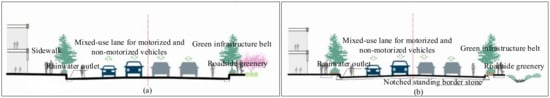
Figure 1.
Traditional single-lane road cross-section layout (a); sponge city single-lane road cross-section layout design (b).
- 2.
- GSI Layout Control Guidelines for Dual Carriageways
Dual carriageways are complex structures comprising a central median, motor vehicle lanes, pedestrian pathways, and side roads. They typically cater to one-way roads with two or more motor vehicle lanes and fewer non-motorized vehicles. In the traditional cross-sectional design shown in Figure 2a, road surface stormwater is primarily managed through a dual-slope drainage pattern, where water flows from the road surface to gutters on either side and is then rapidly discharged through storm drains. Figure 2b offers optimization guidelines for the traditional dual-carriageway cross-section and introduces a design scheme for sponge-type dual carriageways. In this design, stormwater inlets are strategically placed within the central green belt, and ecological tree pits are utilized around the roadside trees. This configuration allows stormwater to naturally flow along the mixed motor and non-motor vehicle lanes towards the central green belt, facilitating effective treatment through green infrastructure. Additionally, surplus stormwater is directed to a dedicated stormwater drainage system, rather than to combined or wastewater sewers, only when necessary, thereby alleviating pressure or overflow on the latter. This design effectively accomplishes source control and efficient treatment of stormwater, significantly enhancing the efficiency of urban stormwater management and reducing the impact on wastewater treatment systems. Dual carriageways, consisting of a central dividing strip, mixed traffic lanes, and side belts, are well suited for urban secondary arterials and expressways without service roads [36].
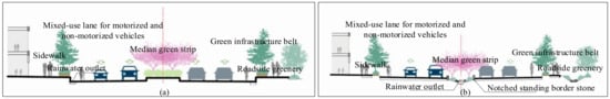
Figure 2.
Traditional dual-lane road cross-section layout (a); sponge city dual-lane road cross-section layout design (b).
- 3.
- GSI Layout Control Guidelines for Triple Carriageways
Triple-carriageway structures, consisting of motor vehicle lanes, dual side medians, non-motorized vehicle lanes, and side belts, are particularly suited for busy urban main roads with a high volume of non-motorized traffic. In the traditional design depicted in Figure 3a, stormwater runoff primarily flows from sidewalks to non-motorized vehicle lanes and then from both motor and non-motorized vehicle lanes to gutters on the sides and is eventually discharged through stormwater pipes. However, the design philosophy for sponge city triple carriageways, as shown in Figure 3b, is markedly different. Here, runoff from both motor and non-motorized vehicle lanes is directed into the landscaped medians on each side. Excess water that exceeds the handling capacity is channeled into stormwater pipes through inlets, while stormwater from sidewalks can directly infiltrate or be directed into ecological tree pits. This design significantly enhances the source control and effective utilization of stormwater, thereby improving the overall efficiency of urban stormwater management [37].
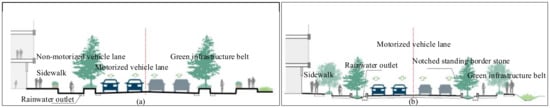
Figure 3.
Traditional triple-lane road cross-section layout (a); sponge city triple-lane road cross-section layout design (b).
- 4.
- GSI Layout Control Guidelines for Quadruple Carriageways
Quadruple-carriageway roads primarily consist of a central median, dual side medians, vehicle lanes, pedestrian paths, and side roads. They are typically used on main arterial roads with high motor vehicle speeds, more than two lanes of one-way motor vehicle traffic, and a significant presence of non-motorized vehicles, as well as on expressways with service lanes [38]. In the traditional design shown in Figure 4a, quadruple carriageways employ a dual-slope drainage model with the central median as the high point, directing stormwater runoff from vehicle lanes towards gutters on both sides. Figure 4b presents optimized control guidelines for traditional quadruple carriageways, featuring a cross-sectional design for sponge-type quadruple carriageways. This design channels stormwater runoff from both motor and non-motorized vehicle lanes towards the side medians, with inlets situated within these medians. Roadside trees are replaced with ecological tree pits to accommodate infiltration or discharge of stormwater runoff from pedestrian pathways. This innovative approach enhances the effectiveness of stormwater management on such roads.
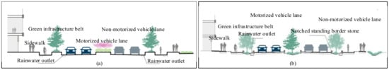
Figure 4.
Traditional quadruple-lane road cross-section layout (a); sponge city quadruple-lane road cross-section layout design (b).
- 5.
- GSI Layout Control Guidelines for Roads with Special Cross-Sections
For roads with notable elevation differences, such as those with distinct uphill and downhill sections, the primary components include a central up-and-down green median, mixed motor and non-motor vehicle lanes, pedestrian paths, and side belts. In the traditional design shown in Figure 5a, drainage relies on road surface stormwater runoff directed towards gutters on both sides, which is then rapidly expelled through stormwater pipes. Figure 5b presents an optimized layout of traditional control guidelines, featuring a sponge-type cross-sectional design. In this design, stormwater inlets are placed within the green belts, and roadside trees are arranged as ecological tree pits. Road surface stormwater is channeled towards the gutters on both sides, while additional inlets are integrated into the central green median to prevent excessive runoff from lower road surfaces, ensuring more effective management and utilization of stormwater. This design not only improves the efficiency of stormwater management but also contributes to enhancing urban greenery and ecological quality.
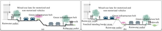
Figure 5.
Traditional elevated bidirectional road cross-section layout (a); sponge city elevated bidirectional road cross-section layout (b).
3. Results
Since the control of peak runoff and pollution can mostly be achieved through the control of total runoff, total runoff control is often selected as the primary control target for green stormwater infrastructure. This study validates the method using a 1 km2 residential area basic unit in Beijing as a generalized research object. According to the requirements of sponge city construction, the sponge equivalence of typical facilities used in the project is calculated to ultimately determine whether the annual total runoff control rate target is achieved. In accordance with the planning and design requirements for residential areas in urban China, the 1 km2 residential area basic unit in Beijing is analyzed and studied, generalized into three parts: buildings, roads, and green spaces. Among them, green spaces account for 30% of the area, mainly including public green spaces, accounting for 7.5–18% of the area, as well as other ancillary green spaces; roads account for 15%, mainly including residential area roads, community roads, group roads, and non-public built resident car ground parking spaces; the building part accounts for 55%, mainly including residential buildings and public buildings [39].
There are many control targets for the construction of sponge cities, with the main control targets being annual total runoff, peak flow rate, and runoff pollution. Among them, the annual total runoff control rate is the primary control target, and the control of other targets can be achieved under the conditions of the annual total runoff control target. Through the analysis of the underlying surface and the comparison of facility technologies under the sponge city design in residential areas, taking Beijing’s multi-year average rainfall data and targets as examples, the annual total runoff control rate is 85%, corresponding to a design rainfall amount H = 33.6 mm. Using the volume method, calculations are carried out for 1 km2, as shown in Table 6.
Table 6.
The storage volume of different underlays in a 1 km2 residential area.
From Table 6, it is known that for a residential area of 1 km2, under the goal of an annual runoff total control rate of 85%, the total volume that needs to be controlled is 16,582 m3. By using the conversion method of runoff volume control equivalents, taking the bioretention cell as the reference, different green stormwater infrastructure elements such as sunken green spaces, permeable pavements, green roofs, and storage tanks are used as examples for individual calculations. According to Table 1, with the typical facility structural construction, the unit equivalent of a bioretention cell is 1, and the sponge equivalence is 0.44 for sunken green spaces, 0.18 for permeable pavements, 0.25 for green roofs, and 4.03 for storage tanks. Taking combinations of two or three of these facilities as examples, the runoff volume control scale results for various different facility area combination schemes are calculated, as shown in Table 7.
Table 7.
Calculation application of different GSI combination schemes.
Table 7 indicates that when aiming for total runoff control in 1 km2, by calculating the effective retention volume of green stormwater infrastructure required per unit watershed area, we can check whether the annual total runoff control target is met. The conversion of runoff volume control equivalents simplifies calculations in typical structural constructions, ensuring that the facility scale in green stormwater infrastructure planning and design is equivalent to actual targets, that combinations of facilities are relatively rational, and that adjusting schemes is convenient. Finally, the best plan can be determined by considering factors such as site type, space size, soil permeability, groundwater level, and economic comparisons.
However, during the construction of sponge cities in China, some standards, specifications, or special plans explicitly point out the detailed indicators of source reduction facility scale that should be met, such as the rate of sunken green space or permeable paving. This method facilitates design simplification and project acceptance assessment, playing a significant role in promoting the application of the sponge city concept to a large extent. However, its drawback is that it does not consider the principle of local conditions, often not starting from a problem-oriented design, and the plan may not be optimal. The reason for this can be found in the fact that there are many types of green stormwater infrastructure, and the control effects and applicable conditions of the facilities vary. If planning or design is limited to the application of several specific facilities, although the scheme can meet the established indicators, there may be problems such as overly single facilities or not considering the site conditions. For example, the planning indicators in the “Stormwater Control and Utilization Engineering Design Code” of Beijing stipulate the following: (1) Projects with a hardened area of 2000 square meters or more should be equipped with stormwater storage facilities, with a specific standard of not less than 30 cubic meters of storage volume per thousand square meters of hardened area. (2) In construction projects involving green space rate indicators, at least 50% of the green space should be used for stormwater retention in sunken green spaces. (3) The permeable paving rate of public parking lots, sidewalks, pedestrian streets, bicycle lanes, leisure squares, outdoor courtyards, etc., should not be less than 70% [40]. These regulations limit the proportion of stormwater storage facilities, sunken green spaces, and permeable paving facilities. If the plan is simply determined according to these regulations, there may be situations where the rationality and limiting factors of its goals are not considered, missing the possibility of various optimization scheme combinations. In fact, the design rainfall amount corresponding to the target annual runoff total control rate determined by the project should be reasonably converted into the runoff control volume of source reduction facilities [41], and then the degree of achievement of goals such as volume control, peak flow control, and pollution control should be analyzed. Finally, comprehensive factors such as prominent problems of the project, site conditions, landscape requirements, and other factors should be considered to determine the optimization scheme.
For the control guideline strategies of urban roads in typical areas, based on the different levels and functional characteristics of urban roads, guidelines for the core control modes of urban roads for urban stormwater are provided, and control is carried out in terms of site space layout and organization. The green spaces inside and outside the road red lines are fully utilized for the comprehensive utilization of stormwater, constructing the control guideline strategies of green stormwater infrastructure in urban roads under the urban planning system.
4. Discussion
In urban design, there are still significant deficiencies in green stormwater infrastructure design, which lacks integration with design goals for stormwater management as well as strategies for implementing the goals of green stormwater infrastructure planning and design. Therefore, it is necessary to discuss and study the problems of green stormwater infrastructure planning and design in urban design.
4.1. Shortcomings of Green Stormwater Infrastructure Planning and Design in Urban Design
Green stormwater infrastructure is a key element in the construction of sponge cities. To facilitate the planning, design, acceptance, evaluation, and monitoring of green stormwater infrastructure in sponge cities, this study introduces the “sponge equivalence” method. By comparing the control effects of different facilities with those of bioretention facilities, this method standardizes the outcomes, making them easier to understand and apply. It is important to note that in practical engineering applications, the influence of multiple factors, especially strategies for total runoff pollution and peak runoff flow control, must be comprehensively considered. Additionally, an in-depth analysis of the construction of green stormwater infrastructure under different environmental conditions in various regions is required to determine the conversion relationships between different types of green stormwater infrastructure. Urban design, as a critical guide for the organization and layout of key urban spaces, currently has significant shortcomings in implementing the concept of sponge cities during the urban design process. This is especially true for key issues such as the rational layout of key urban spaces, vertical control connections, connections between different specialties, and the relationships between drainage systems. There is a lack of effective response strategies. Addressing these key issues is a bottleneck that needs to be broken through in current urban design and sponge city construction [42]. Integrating the concept of sponge cities into the urban design process and strengthening the planning and design control guidance of green stormwater infrastructure in urban design can provide effective control guidance for urban spatial layout. However, China’s existing urban planning system is insufficiently supportive of sponge city construction, mainly manifested in the following aspects: lack of integration of sponge city concepts, unreasonable spatial layout, lack of adherence to the “source reduction, process control, system governance” approach, insufficient qualitative and quantitative analysis, insufficient connection between spatial layout planning and specialized planning, and inadequate attention to vertical planning in cities. Therefore, understanding these urban planning issues and effectively implementing sponge city construction content and requirements in urban planning are key to effectively solving urban water environment problems.
With the continuous advancement of sponge city construction, it is crucial to analyze the key issues currently facing sponge city construction and urban design and to explore key control and guidance strategies for urban design based on the concept of sponge cities. This will clarify the scope and systematic relationships involved in urban design under the concept of sponge cities. Starting from key areas and spatial control guidance in the city, this approach strengthens the control and guidance role of urban design and green stormwater infrastructure planning, thereby defining the development strategies of green stormwater infrastructure in urban design and providing references for sponge city construction and urban design work in China.
4.2. Goals and Principles of Green Stormwater Infrastructure Planning and Design in Urban Design
(1) Planning and Design Goals: Through rational planning and design of green stormwater infrastructure, implement measures such as “infiltration, retention, storage, purification, use, and drainage” to the greatest extent possible to maintain the natural circulation system of the original ecological environment. The goal is to create an urban ecosystem that combines the harmonious development of urban spatial patterns and the environment, thereby optimizing the urban spatial pattern and improving the rationality of urban spatial layout. Therefore, integrating the original ecological environment, especially the hydrological state before development, into urban planning is crucial. This ensures that urban planning fully considers ecological priorities and provides control guidance for planning and design layouts, achieving comprehensive consideration across multiple objectives and domains and promoting the optimization of urban layout. In addition, using platform technologies such as ArcGIS to build a connection platform between urban planning and sponge city construction, we can extend the application of ecological sensitivity analysis methods in sponge cities to the construction of urban spatial patterns and then determine the analysis methods and guidance strategies for constructing urban spatial patterns.
(2) Planning and Design Principles: Change the traditional spatial layout methods and use reasonable connections between multiple systems and multiple objectives to construct an urban spatial system that prioritizes ecology and natural benign circulation. Combine the construction methods of the sponge city stormwater comprehensive system to establish a source reduction system, drainage pipe system, excessive stormwater runoff control system, and flood prevention system on one map. Decompose specific influencing factors of each system, such as hydrology and soil, and combine them with urban planning layout influencing factors, such as land zoning and current land use status, for comprehensive overlay analysis. This will lead to a comprehensive layout form that takes into account both urban planning and green stormwater infrastructure planning and design. Fully utilize the storage function of natural channels, lakes, and other natural spaces for rainfall; strengthen the connection between urban land layout planning, vertical planning, and the hydrological state before development; and analyze current urban issues, especially controlling the layout scale of different land use types, underlying surface requirements, facility scale, etc. In urban planning, it is crucial to fully utilize natural spaces such as natural channels and lakes for their capacity to accumulate rainfall, while also strengthening the cohesion between urban land use layout planning, vertical planning, and the pre-development hydrological state. This includes a thorough analysis of current urban issues, especially in controlling the layout scale of different land use types, substrate requirements, and facility sizes. Furthermore, a comprehensive consideration of transportation and highway engineering, public transit planning, and other fields is essential, coordinating the functions of natural ecology and artificial interventions. Through such an integrated approach, urban planning directions can be reasonably adjusted to construct an overarching strategy that includes source reduction, process control, and systemic governance. This aims to achieve a more efficient and sustainable urban development model, where the smooth flow of traffic, convenience of public transportation, and environmental friendliness of urban infrastructure become key components of the overall plan. Fully respect nature, primarily use local plant species for natural configuration to achieve an effect of “originating from nature, surpassing nature”, and create a diverse plant ecological landscape to enrich seasonal and color changes. Increase the layers and varieties of plant landscapes to create a beautiful and comfortable landscape environment. Plants in different functional zones should be appropriately selected according to the landscape and local conditions, highlighting the theme of each zone, enhancing regional characteristics, and embodying the connotation of ecological culture. Maximize the provision of cozy planting spaces as much as possible, achieving a “green wherever possible” approach, and accentuate the landscape’s charm and romantic appeal through thoughtful planting. When selecting plants for green stormwater infrastructure, it is essential to consider a range of factors including moisture conditions, the quality of runoff stormwater, and seasonal variations. It is advisable to choose native plants that are tolerant to salt, inundation, and pollution and capable of adapting to seasonal changes. This ensures ecological benefits and aesthetic appeal throughout the year.
4.3. Implementation of Goals for Green Stormwater Infrastructure Planning and Design in Urban Design
To ensure the precision and effectiveness of green stormwater infrastructure planning and design, it is necessary to clarify the main planning and design issues currently faced and potentially faced in the future through field surveys, data research, and analysis of basic data and to formulate systematic strategies for these issues. In combination with the construction goals of sponge cities, establish a suitable planning and design system, implement engineering and non-engineering measures at different scales, and solve problems caused by urban development, such as waterlogging and runoff pollution. To achieve the comprehensive goals of sponge cities in terms of “water ecology, water environment, water resources, and water safety”, a comprehensive system including source reduction systems, drainage pipe systems, excessive stormwater runoff control systems, and flood prevention systems needs to be constructed [43]. A source reduction system controls runoff through green infrastructure according to special plans; a drainage pipe system should be built as a perfect separated drainage system, be optimized in combination with open spaces, reduce the use of pumping stations, and lower energy consumption; an excessive stormwater runoff control system should establish channels and storage spaces to deal with excessive runoff, reserve space for future development, achieve comprehensive utilization of water resources, and connect with the city’s water system ecological restoration and flood prevention systems [44]. A source reduction system controls and utilizes stormwater on-site through facilities such as green roofs and rain gardens in various spaces, achieving the goal of controlling runoff volume and pollutant load. Priority should be given to stormwater infiltration and utilization to promote the comprehensive utilization of stormwater. A drainage pipe system needs to be constructed as a perfect separated drainage system, solve the problem of mixed connections, achieve annual runoff total volume control through pipeline transformation and adjustment control, and achieve the control target. An excessive stormwater runoff control system includes drainage channels, discharge channels, and storage spaces, aiming to improve the city’s defense capability against waterlogging, reduce the damage and loss caused by heavy rainfall, and achieve “no waterlogging in heavy rain”. An effective combination of storage and drainage measures is required to control the peak flow of external drainage stormwater, reducing the flood risk to downstream areas.
5. Conclusions
This study selects green stormwater infrastructure planning and design as the starting point. Based on the analysis of sponge city planning and construction needs, it explores the planning and design of green stormwater infrastructure from the perspective of urban design. It summarizes the intrinsic connection between sponge cities and urban design and delves into urban design control and guidance strategies based on sponge city principles in typical areas and urban roads. The aim is to control and guide planning and design from the source and propose a planning and design method for green stormwater infrastructure based on sponge equivalents. The results show that for a residential area of 1 km2, to achieve the annual runoff total control rate target of 85%, the method of converting runoff volume control equivalents, using bioretention pools as a benchmark, allows for the calculation of various combinations of areas of different types of green stormwater infrastructure, such as sunken green spaces, permeable paving bricks, green roofs, and water storage tanks. This optimizes the planning index of Beijing, which mandates stormwater detention facilities for new projects with a hardened surface area of 2000 m2 or more.
This method and its conclusions provide technical support for the optimization of green stormwater infrastructure planning and design, as well as for the assessment of sponge city construction effects. The introduction of the sponge equivalent concept and the application of its conversion method facilitate the planning, design, acceptance, assessment, and monitoring evaluation of sponge city green stormwater infrastructure. By converting typical green stormwater infrastructure into sponge equivalents, it is possible to more intuitively determine its reasonable scale during planning, design, and assessment, making it easier to optimize facility combinations according to actual situations. Sponge equivalents enable a relatively rational judgment through the conversion relationships between key indicators among facilities, facilitating multi-plan selection for different projects using different stormwater infrastructures. It is also applicable for the rapid assessment of the effectiveness and compliance of green stormwater infrastructure in existing projects. This approach has strong practical significance for the current selection of facilities in sponge city construction and the evaluation of sponge cities. Future research could further explore the applicability of the sponge equivalence concept in different urban settings and how it can be integrated with other environmental impact assessment methods to achieve a more comprehensive and holistic urban water management strategy.
Author Contributions
J.O.: writing—original draft, data curation, and writing—editing. J.L.: writing—methodology, review and editing. X.L.: data analysis. J.Z.: review and editing. All authors have read and agreed to the published version of the manuscript.
Funding
This research was funded by National Key R&D Program of China (2021YFC3200700).
Data Availability Statement
The data presented in this study are available upon request from the corresponding author. The data are not publicly available due to the confidential nature of the research project.
Acknowledgments
The authors thank the anonymous reviewers for their valuable comments.
Conflicts of Interest
The authors declare no conflict of interest.
References
- Zhang, C.Y.; Liu, G.Q.; Zhang, K.H.; Wang, J.Z. Experience and Enlightenment of Urban Waterlogging Management in Hong Kong. China Water Wastewater. 2023, 1–9. [Google Scholar] [CrossRef]
- Hörnschemeyer, B.; Henrichs, M.; Dittmer, U.; Uhl, M. Parameterization for Modeling Blue–Green Infrastructures in Urban Settings Using SWMM-UrbanEVA. Water 2023, 15, 2840. [Google Scholar] [CrossRef]
- Huang, D.; Liu, X.; Jiang, S.; Wang, H.; Wang, J.; Zhang, Y. Current state and future perspectives of sewer networks in urban China. Front. Environ. Sci. Eng. 2018, 12, 2. [Google Scholar] [CrossRef]
- Wu, X.W.; Huang, S.H.; Huang, Y.X.; Chang, Y. Smart Drainage Practices in the Construction of Sponge City in Guangzhou. Environ. Eng. 2023, 11, 110–114. [Google Scholar] [CrossRef]
- Zhang, W.; Che, W.; Wang, J.L.; Wang, S.S. Using Green Infrastructure to Control Urban Runoff. China Water Wastewater 2011, 27, 22–27. [Google Scholar] [CrossRef]
- Wang, C.X.; Lin, G.S. Urban Green Stormwater Infrastructure Planning and Implementation: The Case of Philadelphia, USA. Landsc. Archit. 2015, 5, 25–30. [Google Scholar] [CrossRef]
- Zhang, W. Research on Campus Planning and Design Based on Sponge City Concept. Low Carbon World 2018, 4, 113–114. [Google Scholar] [CrossRef]
- Huang, G.R.; Yang, G.; Zeng, B.W.; Lü, Y.P.; Ren, X.X. Urban Flood Disaster Regulation Based on the Integration of Green-Gray-Blue Infrastructure. J. Zhengzhou Univ. Eng. Sci. 2023, 2, 14–21+74. [Google Scholar] [CrossRef]
- Shafique, M.; Kim, R. Green Stormwater Infrastructure with Low Impact Development Concept: A Review of Current Research. Desalin. Water Treat. 2017, 83, 16–29. [Google Scholar] [CrossRef]
- Qi, M.W.; Liu, F.J. Ecological Hazards of Urban Water Eutrophication and Its Control Measures. Environ. Sci. Dyn. 2004, 1, 44–46. [Google Scholar] [CrossRef]
- Benton-Short, L.; Keeley, M.; Rowland, J. Green Infrastructure, Green Space, and Sustainable Urbanism: Geography’s Important Role. Urban Geogr. 2018, 40, 330–351. [Google Scholar] [CrossRef]
- Wang, Z.M.; Lü, L.; Wang, F. Construction and Restoration Strategies of Green Infrastructure Networks in Mountainous Counties Based on Multi-source Data: A Case Study of Wanzhou District, Chongqing. Trop. Geogr. 2023, 1–12. [Google Scholar] [CrossRef]
- Ge, M.; Huang, Y.; Zhu, Y.; Kim, M.; Cui, X. Examining the Microclimate Pattern and Related Spatial Perception of the Urban Stormwater Management Landscape: The Case of Rain Gardens. Atmosphere 2023, 14, 1138. [Google Scholar] [CrossRef]
- Su, D.J.; Liu, X.; Dong, J.; Cai, L.; Mao, X.Y.; Liu, J. Discussion on the Definition and Calculation Method of Annual Runoff Pollution Reduction Rate in Sponge Cities. China Water Wastewater 2021, 1–7. [Google Scholar]
- Zhao, S.Q.; Jin, C.T.; Li, X.L.; Zhou, Y.W. Application of SWMM Model in a Certain Area of Beijing. Water Supply Drain. 2009, 45, 448–451. [Google Scholar] [CrossRef]
- Lin, J. Exploration of Low-Impact Design of Urban Green Space and Sponge City Construction. Jiangxi Build. Mater. 2017, 20, 25. [Google Scholar] [CrossRef]
- Wei, Z.S.; Wang, X. Inspiration from Ancient Chinese Stormwater Utilization for Contemporary Sponge City Construction. Huazhong Archit. 2016, 34, 132–136. [Google Scholar] [CrossRef]
- Che, W.; Qiao, M.X.; Wang, S.S. Modern Inspiration from Ancient Chinese Stormwater Management Practices. In Proceedings of the National Drainage Committee 2012 Annual Conference, Nanning, China, 1 November 2012; pp. 8–15. [Google Scholar]
- Zhang, R.L. From “Yuan Ye” to “Sponge City”: Exploring the Inheritance and Innovation of Sustainable Landscape Architecture. Low Carbon World 2019, 9, 184–185. [Google Scholar] [CrossRef]
- Che, W.; Zhao, Y.; Li, J.Q.; Wang, W.L.; Wang, J.L.; Wang, S.S.; Gong, Y.W. Interpretation of Sponge City Construction Guide: Basic Concepts and Comprehensive Goals. China Water Wastewater 2015, 31, 1–5. [Google Scholar] [CrossRef]
- Li, J.Q.; Wang, W.L. Construction and Prospect of Urban Stormwater System Based on Multiple Objectives. Water Supply Drain. 2015, 51, 1–3. [Google Scholar] [CrossRef]
- Wang, W.L. Research on the Construction Technology and Strategy of Urban Stormwater System Based on Multiple Objectives. Ph.D. Thesis, China University of Geosciences, Beijing, China, 2015. [Google Scholar]
- Liu, L.J.; Wang, S.S.; Zhang, Z.M.; Dong, Y. Exploration of Planning Implementation Approaches of Multi-Scale Urban Green Stormwater Infrastructure. Landsc. Archit. 2017, 1, 123–128. [Google Scholar] [CrossRef]
- Wang, M.; Chen, F.; Zhang, D.; Rao, Q.; Li, J.; Tan, S.K. Supply–Demand Evaluation of Green Stormwater Infrastructure (GSI) Based on the Model of Coupling Coordination. Int. J. Environ. Res. Public Health 2022, 19, 14742. [Google Scholar] [CrossRef] [PubMed]
- Jiao, S.; Dai, Y.J.; He, Y.X. Planning Method and Application of Green Stormwater Infrastructure. Planner 2017, 33, 49–55. [Google Scholar] [CrossRef]
- Wang, J.N.; Yang, J.T.; Cao, D.; Gao, S.T.; Ge, C.Z.; Qian, X.P. Reform Design of China’s Pollutant Discharge Fee Standard System. Res. Environ. Sci. 1998, 5, 4–10. [Google Scholar] [CrossRef]
- Zhang, D.; Mei, C.; Ding, X.; Liu, J.; Fu, X.; Wang, J.; Wang, D. Impacts of Rainstorm Characteristics on Runoff Quantity and Quality Control Performance Considering Integrated Green Infrastructures. Sustainability 2022, 14, 11284. [Google Scholar] [CrossRef]
- Zhang, X.Y.; Li, Y.; Wang, C.Y.; Chen, Z.X.; Jia, H.F. Methods for Layout of Sponge Source Facilities in Future Communities Aimed at Different Needs. J. Tsinghua Univ. Sci. Technol. 2023, 9, 1483–1492. [Google Scholar] [CrossRef]
- Zhang, Y.Y.; Li, S.Y.; Song, T. Problems and Development Suggestions for the Road Network System in China’s Megacities. Urban Roads Bridges Flood Control. 2016, 14–16. [Google Scholar] [CrossRef]
- Kong, Y. Research on Marxist Ecological View in the Perspective of Ecological Civilization Construction. Environ. Eng. 2023, 41, 358. [Google Scholar]
- Wang, X.Y.; Geng, S.W.; Wang, D.; Dong, Z.H. Discussion on the Drainage Design of Municipal Roads and Key Issues under the Concept of Sponge City. Water Supply Drain. 2022, 58, 569–573. [Google Scholar] [CrossRef]
- Wei, C.; Wang, J.; Li, P.; Wu, B.; Liu, H.; Jiang, Y.; Huang, T. A New Strategy for Sponge City Construction of Urban Roads: Combining the Traditional Functions with Landscape and Drainage. Water 2021, 13, 3469. [Google Scholar] [CrossRef]
- Wang, Z.F.; Huang, R.; Hai, X.; Liu, R.; Ma, J.; Ma, Z.B.; Liu, Y.Y. The Application of Cross-disciplinary Integration in Road Sponge Transformation. Water Supply Drain. 2023, S1, 659–664. [Google Scholar] [CrossRef]
- Li, Q. Application of Sponge City Concept in Municipal Road Water Supply and Drainage Design. J. Theor. Res. Urban Constr. Electron. Ed. 2023, 7, 193–195. [Google Scholar] [CrossRef]
- Wan, M.H. Research on the Planning and Design Method of Urban Road Cross-Section and Its Application. Master’s Thesis, Southeast University, Nanjing, China, 2004. [Google Scholar]
- Wang, X.C. Application and Key Point Analysis of Sponge City Construction in Urban Road Design. Water Purif. Technol. 2019, 38, 42–45. [Google Scholar] [CrossRef]
- Wang, Y.R. Research on Urban Road Landscape Design from the Perspective of Sponge City in Guanzhong City. Master’s Thesis, Chang’an University, Xi’An, China, 2017. [Google Scholar]
- Wang, P. Research on the Refined Design of Urban Road Cross-Section Based on the Concept of Sponge City. Eng. Technol. Res. 2021, 6, 222–223. [Google Scholar] [CrossRef]
- Chen, X. Research on Humanized Space Design of Residential Areas. Master’s Thesis, Taiyuan University of Technology, Taiyuan, China, 2019. [Google Scholar]
- Zou, M. Impact of Underlying Surface Structure Changes on the Comprehensive Runoff Coefficient of Urban Construction Projects. Master’s Thesis, Beijing Forestry University, Beijing, China, 2018. [Google Scholar]
- Deng, D.P.; Chen, X.; Liu, N.C.; Wang, Y.Y. Analysis of the Optimal Design Rainfall in Zhangjiakou City Based on Runoff Pollution Control Volume. J. Hebei Inst. Archit. Sci. Technol. 2018, 36, 71–76. [Google Scholar] [CrossRef]
- Xu, L.; Wu, Z.S.; Shao, Z.Y.; Li, S.; Chai, H.X.; Gong, H.F. Design Method and Application of Road Runoff Conveyance Channels Based on the SWMM Coupled Model. China Water Wastewater 2021, 1, 114–120. [Google Scholar] [CrossRef]
- Wang, Y.T. Research on Planning and Design Methods and Cases of Road for Urban Major Drainage System. Master’s Thesis, Beijing University of Civil Engineering and Architecture, Beijing, China, 2017. [Google Scholar]
- Zhang, C. Drainage Engineering Design Based on the Construction Concept of Sponge City. Water Supply Drain. 2019, 45, 1–5. [Google Scholar] [CrossRef]
Disclaimer/Publisher’s Note: The statements, opinions and data contained in all publications are solely those of the individual author(s) and contributor(s) and not of MDPI and/or the editor(s). MDPI and/or the editor(s) disclaim responsibility for any injury to people or property resulting from any ideas, methods, instructions or products referred to in the content. |
© 2023 by the authors. Licensee MDPI, Basel, Switzerland. This article is an open access article distributed under the terms and conditions of the Creative Commons Attribution (CC BY) license (https://creativecommons.org/licenses/by/4.0/).