Abstract
In subsurface irrigation systems in desert areas, the wetting front transport pattern allows the determination of irrigation flow and timing. In this study, an indoor subsurface irrigation experiment on aeolian sandy soil is designed, and the vertical and horizontal wetting front movement distances under different irrigation flows are obtained. The dimensional analysis method was used to perform a dimensional analysis on the experimental data. An empirical setting front distance estimation model, which only considers three parameters, saturated hydraulic conductivity Ks, irrigation flow Q, and total irrigation volume V, was proposed. The model’s accuracy was statistically evaluated with the observed data and verified by a numerical simulation using HYDRUS-2D/3D. The mean absolute error (MAE) and root mean square error (RMSE) of the proposed model in the horizontal and downward directions were 0.80 and 0.95 cm, respectively, with a percentage bias (PBIAS) of −3.47 ≤ ±10 and a Nash–Sutcliffe efficiency (NSE) of 0.98, which is close to 1. Thus, this model can contribute to the selection of the appropriate depth and spacing of subsurface laterals.
1. Introduction
Sand-fixing vegetation is the preferred approach to prevent wind and sand disasters and build ecological barriers in sandy areas [1]. Due to the limited water resources in the desert, sand fixation by plants is also greatly limited. At present, the irrigation system in plant sand-fixing areas is generally surface irrigation, while the intense evaporation and low water capacity in desert areas lead to low irrigation efficiency [2]. An efficient irrigation method is required to reduce surface evaporation in desert areas while satisfying the need for a precise water supply to plant roots.
Subsurface irrigation, a water-saving irrigation method for deep-rooted plants, and direct plant root irrigation increase water use efficiency by creating a wetter local root zone [3,4,5]. Subsurface irrigation provides significant water savings compared to surface drip and surface sprinkler irrigation methods [6,7,8,9,10]. Meshkat et al. [11] replaced the soil under an emitter with coarse sand to form the early Sand Tube Irrigation (STI) method. They found that soil water evaporation from surface drip irrigation was much greater than that from sand tube irrigation. The results of field trials conducted by Yanni et al. [12] in a similar manner showed that the water content of the root distribution area was significantly higher for sand tube irrigation than surface drip irrigation at the same irrigation level. Studies have shown that subsurface irrigation has a more obvious advantage of saving 30–70% of water compared to surface irrigation [13,14,15].
There are many factors affecting the water infiltration pattern of irrigated soils, such as the physical properties of the soil, initial water content, bulk weight, soil matrix content, irrigation volume, and flow rate [16,17,18]. Huang et al. showed that the nature of the soil is the most important factor affecting the infiltration pattern [19,20]. Li et al. [21] studied the distribution pattern of wet fronts under four influencing factors: irrigation quota, irrigation flow, initial soil moisture content, and capacitance. Among them, irrigation water quantity and irrigation flow rate have a great influence on the transport of wetting fronts. Fan et al. [22] concluded from an indoor subsurface irrigation experiment that irrigator burial depth has a significant effect on the location of the water distribution and the volume of wetted bodies.
In subsurface irrigation systems, the design of the irrigation scheme directly affects the geometry of the wetting front and is of considerable importance for efficient water use [23,24,25]. The transport distance of wetting fronts in vertical and horizontal directions is an important parameter to characterize the movement law of wetting fronts [26], and the establishment of infiltration models to calculate the geometry of wetting fronts is a common method used to describe the soil moisture transport law, and numerous studies have been conducted by scholars, as presented in Table 1. The infiltration models are mainly established by equation derivation, inverse analysis, and data fitting, and the main types of models according to different methods are mathematical, numerical, and empirical [22,27,28,29,30,31,32,33,34,35]. The HYDRUS-2D/3D soil water transport simulation software developed by Van Genuchten and Simunek is a numerical simulation method based on the theory of unsaturated soil hydrodynamics used to quantitatively describe the soil wetting front movement patterns and water transport distribution characteristics under subsurface irrigation conditions [36], and has been widely used in soil water transport studies for point- and line-source irrigation methods because of its accurate simulation results [28,29,30,31].
Mathematical and numerical models are limited by the starting conditions, boundary conditions, and basic physical properties of the soil, as well as the high computational power [37,38,39]. Empirical models are applicable to the corresponding soil properties and irrigation methods, due to their simplicity and easy access to parameters, which makes them more convenient to apply in the field [40]. Cristobal-Munoz and Al-Ogaidi et al. conducted surface point source irrigation experiments on different soils and fitted empirical models for a wide range of parameters [32,35]. Most of the literature to date has developed infiltration models for surface irrigation, and there are fewer studies on infiltration models for subsurface irrigation [41,42]. Fan et al. developed an empirical model of cumulative irrigation infiltration through subsurface vertical line source irrigation experiments [22]. Wang et al. fitted an empirical model of wetting peak transport based on the experimental data from in-line subsurface drip irrigation trials [43]. Most empirical models are based on specific experimental conditions and are built by means of statistics on the experimental data.

Table 1.
Wetting front movement calculations for various soils under different irrigation methods.
Table 1.
Wetting front movement calculations for various soils under different irrigation methods.
| Category | Applied Soil | Irrigation Method | Equation | Basis for Establishment |
|---|---|---|---|---|
| Mathematical Model | Silt | Surface point source [27] | Derivation of Richards’ equation | |
| Numerical Model | All soil types [28,29,30,31] | - | Inversion of soil parameters | |
| Empirical Model | Sandy clay loam | Surface point source [32] | Test fitting | |
| All soil types | Surface point source [33] | |||
| Loam, sandy loam | Point source [34] | |||
| All soil types | Surface [35] | |||
| All soil types | Surface [38] | |||
| Loam, silty and sandy loam | Subsurface line source [22] |
Notes: H is the horizontal dimension of the wetting front (cm); D is the vertical, downward dimension of the wetting front (cm); Q is the irrigation flow (L/h); d is the maximal width of wetting body (cm); Ks is the saturated hydraulic conductivity (cm/s); t is the irrigation time (h); θi is the initial water content (cm3/cm3); θf is the water content near the wetting front (cm3/cm3); θs is the saturated water content (cm3/cm3); Pb is the soil bulk weight (g/cm3); OM is the percentage of organic matter (%); d is the infiltration source diameter; L is the line source length; S, Si, and C are the percentages of sand, silt, and clay in the soil (%), respectively; Se is the relative saturation of soil (cm3/cm3); α and n denote fitting parameters, m = 1 − 1/n, n > 1; α denotes the parameter related to the physical properties of the soil (cm−1); h denotes the substrate potential (cm); l denotes the connectivity parameter, usually taken as 0.5.
The gauge theory can be briefly described as follows: any equation involving n physical quantities is equivalent to an equation involving only a lower number of dimensionless quantities, and this equivalence simplifies physical problems. Establishing the intrinsic connections and quantitative functional relationships between these physical quantities allows the establishment of scientifically accurate, similar models [44,45]. The use of dimensional analysis can not only reduce the number of experiments and optimize the experimental design, but can also reduce the difficulty of data processing and reflect the laws between physical quantities with fewer physical quantities; therefore, it has attracted considerable interest from researchers. At present, the dimensional analysis method has been applied for the calculation of neural dynamics, the establishment of equations for the asymmetric discontinuous cross-slope bracing system, and the prediction of tunnel-boring machine performance [46,47,48]. However, few subsurface irrigation models have been developed to describe wetting peak geometry using the volume analysis method. Moreover, the soils studied in most infiltration models at present are mostly loamy, chalky, and sandy soils common in economic crops [22,32,33,34,35], and there are few relevant studies for wind-deposited sands in desert areas [49,50].
Therefore, in this paper, the multiple physical quantities involved in the test are simplified into dimensionless equations by using the dimensional analysis method based on the test data through an indoor aeolian sandy soil subsurface irrigation test. The experimental data are dimensionlessly processed and the model is established by the derivation of corresponding equations. The correctness of the proposed model is verified and compared with the numerical model. A less parametric model for predicting the transport distance of a wetting front of aeolian sandy soil is proposed and validated.
2. Materials and Methods
2.1. Infiltration Experiment of Aeolian Sand
2.1.1. Experimental Soil Characteristics
Aeolian sandy soil was collected from Ba Chu County (39°52′32″ N 78°39′13″ E), which is located at the edge of the Taklamakan Desert in Xinjiang, China. The sampling site was located on a flat sandy area 1000 m away from the upwind side of the G217 road. The basic physical properties of aeolian sandy soil are presented in Table 2. Among them, the particle size was obtained through the sieving method, the saturated water content was obtained through the drying method, and the saturated hydraulic conductivity was obtained through the variable-head permeability test. These tests are completed in strict accordance with the provisions of the Standard for geotechnical testing method (GBT50123-2019).

Table 2.
Basic physical properties of aeolian sandy soil.
2.1.2. Experimental Setup
As presented in Figure 1, the test equipment consists of three parts: a Markov bottle, an irrigator, and a sand-filled, glass, soil box. The Markov bottle used in the test controlled the flow magnitude, and the irrigation volume was observed and recorded by adjusting the switch opening to control the irrigation flow. A PVC pipe 30 cm long and 2 cm in diameter was used as an irrigator in the experiment. Referring to the experimental design in the literature and the design of the subsurface irrigation system attached to the wind-deposited sand sampling site, the water supply port was buried 20 cm below the soil surface [41,51]. The water supply port was designed with a closed end and a uniformly open hole (aperture of 2 mm) in the body of the tube 4 cm upwards and covered with a non-woven fabric, while the tube was filled with gravel with a grain size of 4~10 mm to prevent the water supply port from being blocked. The irrigator was connected to the Markov bottle by a rubber hose. The test soil box was an 8 mm thick PVC transparent soil box with an inner diameter of 60 cm × 20 cm × 70 cm. The bottom of the soil box was drilled to prevent the occurrence of water stagnation due to air resistance [32,41]. Using the position of the bottom of the irrigator as the origin of the wetting front transport coordinates, (0,0) to (0,4) were the outflow interfaces for subsurface irrigation.
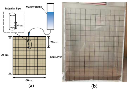
Figure 1.
Drip irrigation experiment steps. (a) Schematic diagram of the drip irrigation process; (b) grid line division.
2.1.3. Experimental Trials
Three sets of tests were conducted depending on the magnitude of the irrigation flow Q. The vertical, upward transport distance U; vertical, downward transport distance D; and horizontal transport distance H of the aeolian sandy soil wetting fronts were recorded at different times. The total irrigation volume V was set to 3 L, and Q was set to 0.5, 1.0, and 1.5 L/h, which corresponded to 360, 180, and 120 min of irrigation time, respectively, and each group of experiments was repeated three times. The specific steps were as follows: (1) divide horizontal and vertical grid lines at 5 cm intervals on the sides of the soil box (Figure 1b); (2) load the samples in layers of 32.865 kg of aeolian sandy soil with a thickness of 5 cm per layer and let stand for 24 h after loading; (3) at the end of the resting period, adjust the Markov bottle to start the irrigation process; (4) and photograph and plot the position of the wetting front on the observation wall of the cube container at the same time. The recording frequency was every 5 min for the 1st hour, every 10 min for the 2nd and 3rd hours, and every 30 min after the 4th hour.
2.2. Model Establishment Method
2.2.1. Wetting Front Distance Model
After deriving the wetting front transport distance data, an irrigation flow of Q = 0.5 L/h was selected for this study. The transport distance formula based on the dimensional analysis was fitted to the unknown parameters [52,53]. On the basis of this formula, a model for wetting front transport pattern estimation was established. Schwartzman [53] set the following quantities in the soil water infiltration problem using the gauge analysis theorem proposed by Buckingham [52]: (1) the vertical, downward infiltration distance D; (2) vertical, upward infiltration distance U; (3) horizontal infiltration distance H; (4) saturated hydraulic conductivity Ks of aeolian sandy soil; (5) irrigation flow Q; and (6) total irrigation volume V. The derivation of the dimensionless formulas for each of the point and line source infiltration sources are also provided:
where is the total amount of point source irrigation; , , and are the upward, downward, and horizontal transport distances of the point source, respectively; is the total amount of line source irrigation; , , and are the upward, downward, and horizontal transport distances of the line source, respectively; is the unit irrigation volume of the line source; and is the unit irrigation flow of the line source.
Schwartzman [53] stated that the dimensionless quantities , , , , , , satisfy the following relation:
where Ai and nj (i,j = 1,…,6) are the equation coefficients and power exponents, respectively.
After deriving the relationship between the dimensionless quantities and their coefficients, the vertical upward, downward, and horizontal transport distances U, D, and H and , for the point and line source infiltration wetting fronts, respectively, can be determined:
The dimensionless processing of the experimental data means that the experimental data were substituted into Equations (1) and (2) for the calculation. The dimensionless quantities , , and were obtained. The dimensionless processed data were fitted with Equation (3) to yield the unknown parameters Ai and nj (i,j = 1,…,6) in Equation (3). Finally, the parameters Ai and nj (i,j = 1,…,6) were substituted into Equations (4) and (5) to derive the wetting front transport distance model.
2.2.2. Wetting Body Elliptical Model
After determining the parameters of the point source infiltration (Equation (4)) and the line source infiltration (Equation (5)) models, the elliptical wetting front model proposed by Moncef [27] et al. was constructed as follows:
where x is the horizontal coordinate of a wet front point and y is the vertical coordinate of a wet front point.
and with the better fit were selected as elliptic equation coefficients a and b, respectively, by statistical analysis, implying that or H and or D. At this point, the coordinates of a wetted front profile point at any moment can be expressed by Equation (7):
2.2.3. Model Evaluation
In this study, four statistical analysis metrics (Equations (8)–(11)), including the mean absolute error (MAE), root mean square error (RMSE), percent bias (PBIAS), and Nash–Sutcliffe efficiency (NSE), were used to statistically analyze the prediction results of the wetting front transport distance (Equations (4) and (5)) and ellipsoidal (7) models.
where Oi denotes the ith experimental observation, Si denotes the ith model prediction, denotes the average of experimental observations, and n is the number of individuals.
When the MAE and RMSE values are close to 0, PBIAS ≤ ±10, the NSE value is close to 1, the predicted values are in good agreement with the observed values, and the difference between them is small [32]. To rate the model according to the NSE values, the Ritter and Muñoz–Carpena [54] criteria were used: unsatisfactory (NSE < 0.65), acceptable (0.65 ≤ NSE < 0.80), good (0.80 ≤ NSE < 0.90), and very good (NSE > 0.90).
2.2.4. Numerical Model
In this study, HYDRUS-2D/3D was used as a numerical method to verify the model results. The most widely used was the Van Genuchten model expressing the soil moisture characteristic and unsaturated hydraulic conductivity curves. Its control equation is:
3. Results
3.1. Wetting Front Distribution
Figure 2 presents the wetting front shape for different Q values after V = 3 L of irrigation. Figure 3 exhibits the variation in the wetting front with time for the three sets of tests. The specific findings are presented as follows: (1) the aeolian sandy soil wetting front shape is similar to that of a “bowl”, with the maximum horizontal distance located 10–15 cm below the outflow interface; (2) the size of the wetting front formed at Q = 0.5 L/h is 9-20% more horizontal and 6% more vertical than at 1.5 L/h; (3) the wetting front area formed by at Q = 1.5 L/h is more significant for the same irrigation duration; and (4) the growth rate of the wetting front transport distance shows an increasing trend, followed by a decreasing trend.
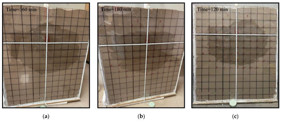
Figure 2.
Wetted body shape under different flow rates. (a) Q = 0.5 L/h; (b) Q = 1.0 L/h; (c) Q = 1.5 L/h.
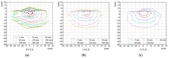
Figure 3.
Wetting front distribution with time. (a) Q = 0.5 L/h; (b) Q = 1.0 L/h; (c) Q = 1.5 L/h.
Figure 4 presents the variation in the wetting front transport distance with time. The following conclusions can be observed: (1) the horizontal and downward wetting front transport rates for each set of tests increase with Q; (2) the increase in both the horizontal and vertical wetting front transport distances decreases with the increasing irrigation time; (3) the wetting front is very short in the vertical, upward direction throughout the course of irrigation and has a nearly constant length in the later stages of irrigation; (4) at the beginning of irrigation, the wetting front transport in the horizontal direction was predominant; with the increase in the irrigation volume, the vertical, downward transport distance gradually increase in the horizontal direction.

Figure 4.
Movement distance in all directions under different flow rates. (a) Downward; (b) horizontal; (c) upward.
3.2. Proposed Model
3.2.1. Wetting Front Distance Model
The equation coefficient Ai and power exponent nj (i,j = 1,…,6) values for each dimensionless transport distance, , , , , , and total irrigation volume are presented in Figure 5 and Figure 6 and Table 3. The equation coefficients Ai and power exponents nj (i,j = 1,…,6) are imported into Equations (4) and (5) to yield the complete transport distance, as presented in Equations (15) and (16).

Figure 5.
Dimensionless relationship between each direction and volume during point source infiltration. (a) Upward; (b) downward; (c) horizontal.

Figure 6.
Dimensionless relationship between each direction and volume during line source infiltration. (a) Upward; (b) downward; (c) horizontal.

Table 3.
Point and line source infiltration characteristic model parameters for wetting body aeolian sand.
Figure 7 and Figure 8 present the comparison with a 1:1 fit line between the distance model predictions and experimental observations for Q = 1.0 L/h and Q = 1.5 L/h. The specific results are given as follows. (1) the distance fitted lines in the vertical, downward direction fit the line source model better, while they fit the point source model worse; (2) the distance fitted lines in the horizontal direction fit the point source model better, while they fit the line source model worse; and (3) the predicted values in the vertical, upward direction differed significantly from the other two sets of test observations regardless of the infiltration mode. The abovementioned results show that the line source infiltration prediction model is more applicable to the vertical, downward direction, and the point source infiltration model is more applicable to the horizontal direction. However, neither model is applicable to calculate the wetting front distance in the vertical, upward direction.
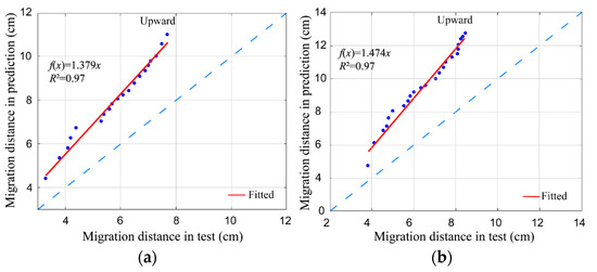
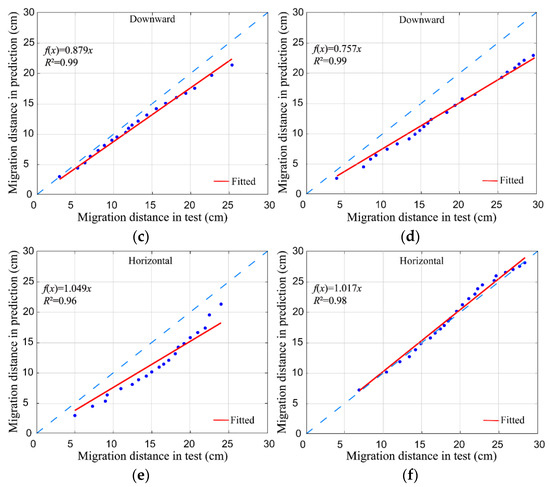
Figure 7.
Comparisons between predicted and observed point source infiltrations. (a) Upward, Q = 1.0 L/h; (b) upward, Q = 1.5 L/h; (c) downward, Q = 1.0 L/h; (d) downward, Q = 1.5 L/h; (e) horizontal, Q = 1.0 L/h; (f) horizontal, Q = 1.5 L/h.
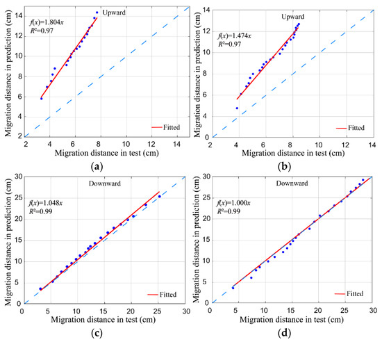
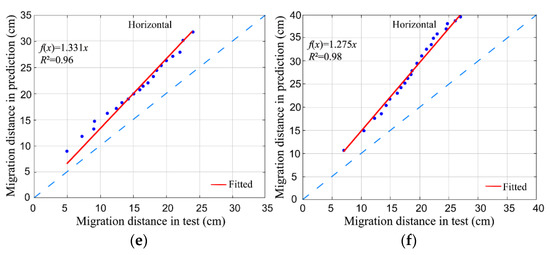
Figure 8.
Comparisons between the predicted and observed line source infiltration. (a) Upward, Q = 1.0 L/h; (b) upward, Q = 1.5 L/h; (c) downward, Q = 1.0 L/h; (d) downward, Q = 1.5 L/h; (e) horizontal, Q = 1.0 L/h; (f) horizontal, Q = 1.5 L/h.
Among the abovementioned fitting results, Figure 6e,f and Figure 7c,f present better results, and the fitted lines are close to 1:1. Therefore, these two models were selected for statistical analysis, and the results of the analysis are presented in Table 4. The predicted values of the two models are in good agreement with the observed values and accurately predict the wetting front transport distance.

Table 4.
Statistical characteristics analysis of the predicted and observed values.
3.2.2. Wetting Body Elliptical Model
Based on the prediction degree of the abovementioned model, the point source infiltration model H, which fits better with the observed data, was selected in the horizontal direction. Similarly, the line source infiltration model fitting better in the downward direction was selected to construct an aeolian sandy soil wetting front elliptical distribution model. By substituting the corresponding parameters A3, A5, n3, and n5 of models H and into Equation (7), the horizontal and vertical coordinates of a wetted front profile point at any time can be obtained.
Figure 9 presents the correlation between the predicted and experimental observations for ellipsoid models with angles of 30° and 60° and a comparison with a 1:1 fit line, and the statistical analysis of the predicted and experimental data is presented in Table 5. The specific results are as follows: (1) the MAE and RMSE maxima of this model for the transport distance in the 30°direction are 0.71 and 0.95 cm, respectively, the deviation percentage maximum is 1.37 ≤ ±10, and the NSE is close to 1; (2) the MAE and RMSE maxima of the transport distance in the 60°direction are 0.88 and 0.96 cm, respectively, the deviation percentage maximum is −3.47 ≤ ±10, and the NSE is close to 1. The results show that the proposed model can accurately predict the wetted front ellipsoid distribution.
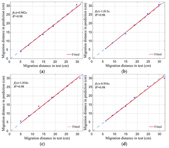
Figure 9.
Comparisons of the predicted and observed values of the models at different angles. (a) Q = 1.0 L/h, 30°; (b) Q = 1.0 L/h, 60°; (c) Q = 1.5 L/h, 30°; (d) Q = 1.5 L/h, 60°.

Table 5.
Statistical characteristics analysis of the predicted and observed values of the models at different angles.
4. Discussion
4.1. Wetting Front Distribution
Figure 3 shows that with an increasing irrigation time or volume in the test, the wetting front formed at Q = 0.5 L/h is greater than that at the other two irrigation flows. The total level of irrigation is the same, and the reduction in irrigation flow produces a greater wetting front distance, similar to the results obtained by Fan et al. [33]. However, the test results contradict Zur’s conclusions [38]. Zur established the relationship between the maximum width d of the wetting soil and its depth z, emitter discharge q, and soil hydraulic conductivity Ks (Equation (18)). In this relationship, the wetting body’s maximum width increases with the increase in the flow rate. For this, we substituted the test parameters into Zur’s model to calculate and draw a comparison. Table 6 shows the comparison results. At the same maximum depth, the test value shows a significant gap compared to Zur’s model. The maximum width in the test was only 36–55% of Zur’s model. Such differences were increased further after setting the interval irrigation, which may be caused by differences in surface and subsurface drip irrigation activities and soil sample parameters. Therefore, we proved that the irrigation flow affects the water movement in the aeolian sand. When the flow is slower, the time to reach the same irrigation volume is longer, resulting in a longer water potential difference duration between the outflow boundary and wetting front.

Table 6.
Comparison of maximum test width d of the test and Zur at the same depth z.
For all the irrigation flows, the wetting front moved rapidly at the beginning of the irrigation and gradually slowed down over time. The increase in both the horizontal and vertical transport distances of the aeolian sandy soil decreased with the increasing irrigation time, which is consistent with the results of Vishwakarma et al. [34]. The reason for this is that the volume of the unwetted aeolian sandy soil increases, there are more pores in the water path, and the wetting front movement rate decreases [27]. It is also because, as the wetting front volume increases, the water potential difference between the outflow boundary and wetting front decreases, decreasing the wetting front transport rate as the drip irrigation time increases.
Figure 3 and Figure 4 show that the wetting front horizontal displacement is greater than the vertical, downward displacement at the beginning of the irrigation process. This is because in the initial moments of irrigation, the movement of water in the aeolian sandy soil is dominated by capillary forces. However, as time passes, the movement of water becomes gravity-driven and begins to dominate, leading to an increase in its vertical advancement and a decrease in its horizontal advancement. The horizontal movement of the wetting front is greater than 10 cm at 60 min following the start of the infiltration process. The soil water movement across the width of the soil box is blocked. This may result in the observed wetting front shape being larger than the actual wetting front shape. According to other studies [22,32], in order to visualize the shape and movement of the wetting front in the soil, the limitation caused by the obstruction of the water’s movement in three dimensions by the side walls of the soil box is also unavoidable. The vertical, upward displacement of the wetting front is approximated in all irrigation flows. This is due to the same aeolian sandy soil matrix potential and vertical, upward transport of water in the capillary force under the dual action of gravity; thus, the transport distance is approximated.
The emitter’s buried depth (20 cm) and outflow interface’s length (4 cm) setting in the test of the water absorption (>70%) by the sand-fixing plants’ roots was generally distributed between 20 and 150 cm [51], while referring to the engineering application. Compared with Fan et al. [22], who used a 30 cm long line source irrigation, the irrigator used in this study had a significant difference, and the size of the outflow interface was smaller than the area of the wetting front. As a result, the water movement simultaneously presented some characteristics of point and a line sources. The horizontal movement was similar to the point source infiltration due to the short outflow interface. Moreover, due to the bottom of the irrigation pipe being sealed in the vertical direction, the outflow was more similar to linear source infiltration. Therefore, the compound infiltration behavior of the horizontal and vertical line sources was evident. In order to clarify the boundary location between the line and point sources, the underground irrigation sleeves with different infiltration boundary heights should be added later to obtain the boundary value between the line and point sources to increase the model’s applicability.
4.2. Comparison with a Numerical Model
The proposed model in this study obtained a more accurate degree of prediction by considering only three factors: saturated hydraulic conductivity Ks, subsurface irrigation flow Q, and total subsurface irrigation V. To discuss the differences between the present model and the numerical method, HYDRUS-2D/3D numerical simulation software was selected for the validation analysis conducted in this study. The hydraulic characteristic parameters of the test aeolian sandy soil samples presented in Table 7 were calculated using the transfer function method (Rosetta model) in HYDRUS-2D/3D based on the particle gradation of the soil. The transport of the wetting front of the wind-deposited sand under subsurface irrigation conditions was simulated by the software, and the numerical simulation results were compared with the predicted values of the constructed model and experimental measured values.

Table 7.
Soil-water characteristic parameters of aeolian sandy soil.
Figure 10 shows the comparison between the numerical simulation values and predicted vertical, downward, and horizontal transport values of the model proposed in this study with the experimental values (when Q is 1 L/h and 1.5 L/h). (1) In the vertical, downward direction, the HYDRUS-2D/3D values are very close to both the empirical model and observed values, and the HYDRUS-2D/3D results when the irrigation flow Q = 1.5 L/h are slightly better than those of the empirical model. (2) In the horizontal direction, the proposed model results are closer to the experimental data than the simulated values of HYDRUS-2D/3D, which significantly differ from the experimental values.
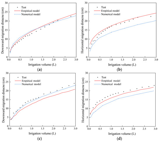
Figure 10.
Comparison between the simulated and observed vertical, downward and horizontal movement distances at different flows. (a) 1 L/h, vertical downward; (b) 1 L/h, horizontal; (c) 1.5 L/h, vertical downward; (d) 1.5 L/h, horizontal.
Table 8 shows the statistical analysis of the two models. The proposed model has lower MAE and RMSE values in both directions and a greater NSE value in the horizontal direction than HYDRUS-2D/3D. The abovementioned results show that the predicted values of the proposed model are in good agreement with those of HYDRUS-2D/3D, and the proposed model has a more accurate prediction degree and smaller relative error in the horizontal direction. The difference between the HYDRUS-2D/3D and test results can be considered. The test soil was filled in layers from the bottom to the top during the filling process, thus ensuring vertical soil compactness but causing local loose or uneven phenomena in the horizontal direction. This discrepancy with the ideal soil set in HYDRUS-2D/3D, which is homogeneous in all directions, led to a poor numerical prediction accuracy in the horizontal direction.

Table 8.
Statistical characteristics analysis of the simulated and observed values of the two models.
In comparison to the numerical model established by the HYDRUS-2D/3D model, the advantage of the proposed model was that it did not require numerous calculations or high-precision experimental equipment, and only a small number of simple parameters, such as saturation hydraulic conductivity Ks, irrigation flow Q, and volume V, were needed to calculate the wetting front range more accurately.
5. Conclusions
In this study, an empirical model for indoor irrigation tests on aeolian sandy soil was proposed on the basis of the gauge analysis method. The proposed model was evaluated and compared using numerical models and experimental data. The model used three parameters: saturated hydraulic conductivity Ks, irrigation flow Q, and total irrigation volume V. It ould estimate the wetting front transport pattern of aeolian sandy soil under subsurface irrigation conditions. The model proposed in this study can guide the design of irrigation systems for desert roads in planted sand control areas.
- (1)
- The aeolian sandy soil wetting front shape resembles a “bowl”. At the same irrigation volume, the wetting front shape is more significant when the flow rate is low, while at the same irrigation time, the wetting front shape is more prominent when the flow rate is significant. As the time increases, the wetting front transport distance increment first increases and then decreases, and the transport direction is mainly horizontal and then vertical.
- (2)
- The point source infiltration model (Equation (12)) is more suitable for calculating the wetting front transport distance in the horizontal direction. The line source infiltration model (Equation (13)) is more suitable for calculating the wetting front transport distances in the vertical direction. The model proposed in this study (Equation (14)) can accurately calculate the wetting front transport pattern of aeolian sandy soil with subsurface drip irrigation.
- (3)
- The prediction degree of the model is consistent with that of HYDRUS-2D/3D and shows a better fit than HYDRUS-2D/3D in the horizontal direction. In practical applications, the model parameters are easy to obtain and use.
Author Contributions
Conceptualization, W.Q. and Z.L.; methodology, W.Q. and Z.L.; software, W.Q. and S.W.; validation, W.Q., Z.L. and Z.Z.; formal analysis, W.Q. and S.W.; investigation, W.Q. and Z.L; resources, D.L. and Z.Z.; data curation, W.Q.; writing—original draft preparation, W.Q.; writing—review and editing, Z.Z., Z.L. and D.L.; supervision, Z.L. and Z.Z.; project administration, D.L.; funding acquisition, D.L. All authors have read and agreed to the published version of the manuscript.
Funding
This research was funded by the Xinjiang Production and Construction Corps Major Science and Technology Plan Project (Grant No.: 2020AA002); key areas of scientific and technological research project (Grant No.: 20190102).
Data Availability Statement
The data presented in this study are available on request from the corresponding author.
Acknowledgments
The authors appreciate the help received from the Editor and anonymous reviewer for their useful comments. This work was financially supported by the Major scientific and technological projects (Grant No.: 2020AA002) and key areas of scientific and technological research project (Grant No.: 20190102). The authors are grateful for this support.
Conflicts of Interest
The authors declare no conflict of interest.
References
- Zhang, J.; Lei, J.; Wang, Y.; Zhao, Y.; Xu, X. Survival and growth of three afforestation species under high saline drip irrigation in the Taklimakan Desert, China. Ecosphere 2016, 7, e01285. [Google Scholar] [CrossRef]
- Wang, Y.; Zhao, Y.; Li, S.; Shen, F.; Jia, M.; Zhang, J.; Xu, X.; Lei, J. Soil aggregation formation in relation to planting time, water salinity, and species in the Taklimakan Desert Highway shelterbelt. J. Soil Sediment 2018, 18, 1466–1477. [Google Scholar] [CrossRef]
- Camp, C.R. Subaurface Drip Irrigation: A Review. Trans. ASAE 1998, 41, 1353. [Google Scholar] [CrossRef]
- Ayars, J.E.; Phene, C.J.; Hutmacher, R.B.; Davis, K.R.; Schoneman, R.A.; Vail, S.S.; Mead, R.M. Subsurface drip irrigation of row crops: A review of 15 years of research at the Water Management Research Laboratory. Agric. Water Manag. 1999, 42, 1–27. [Google Scholar] [CrossRef]
- Cote, C.M.; Bristow, K.L.; Charlesworth, P.B.; Cook, F.J.; Thorburn, P.J. Analysis of soil wetting and solute transport in subsurface trickle irrigation. Irrig. Sci. 2003, 22, 143–156. [Google Scholar] [CrossRef]
- Kang, Y.H.; Ma, X.Y.; Li, J.; Zhao, W.J. Research and Development on Subsurface Drip Irrigation Techni Que. J. Irrig. Drain. 2007, 6, 34–40. (In Chinese) [Google Scholar]
- Xuan, C.; Ding, R.; Shao, J.; Liu, Y. Evapotranspiration and Quantitative Partitioning of Spring Maize with Drip Irrigation under Mulch in an Arid Region of Northwestern China. Water 2021, 13, 3169. [Google Scholar] [CrossRef]
- Kalfountzos, D.; Alexiou, I.; Kotsopoulos, S.; Zavakos, G.; Vyrlas, P. Effect of Subsurface Drip Irrigation on Cotton Plantations. Water Resour. Manag. 2007, 21, 1341. [Google Scholar] [CrossRef]
- Çetin, O.; Kara, A. Assesment of water productivity using different drip irrigation systems for cotton. Agric. Water Manag. 2019, 223, 105693. [Google Scholar] [CrossRef]
- Cetin, O.; Uzen, N.; Temiz, M.G.; Altunten, H. Improving Cotton Yield, Water Use and Net Income in Different Drip Irrigation Systems Using Real-Time Crop Evapotranspiration. Pol. J. Environ. Stud. 2021, 30, 4463–4474. [Google Scholar] [CrossRef]
- Meshkat, M.; Warner, R.C.; Workman, S.R. Evaporation reduction potential in an undisturbed soil irrigated with surface drip and sand tube irrigation. Trans. ASAE 2000, 43, 79–86. [Google Scholar] [CrossRef]
- Yanni, S.; Nimah, M.N.; Bashour, I. Gravel vertical mulching for improving water use efficiency of drip irrigated orchards. Acta Horticulturae. 2004, 9, 664. [Google Scholar] [CrossRef]
- Adamsen, F.J. Irrigation Method and Water-Quality Effect on Peanut Yield and Grade. Agron. J. 1989, 81, 589–593. [Google Scholar] [CrossRef]
- Ma, X.; Sanguinet, K.A.; Jacoby, P.W. Direct root-zone irrigation outperforms surface drip irrigation for grape yield and crop water use efficiency while restricting root growth. Agric. Water Manag. 2020, 231, 105993. [Google Scholar] [CrossRef]
- Montoya, F.; Sánchez, J.M.; González-Piqueras, J.; López-Urrea, R. Is the Subsurface Drip the Most Sustainable Irrigation System for Almond Orchards in Water-Scarce Areas? Agronomy 2022, 12, 1778. [Google Scholar] [CrossRef]
- Moncef, H.; Khemaies, Z. Optimizing Emitters’ Density and Water Supplies in Trickle Irrigation Systems. Am. J. Water Sci. Eng. 2019, 5, 16–21. [Google Scholar] [CrossRef]
- Jin, Y.; Shuqian, W.; Dan, X. Experimental Investigations on Influence of Fracture Networks on Overland Flow and Water Infiltration in Soil. Water. 2022, 14, 3483. [Google Scholar]
- Dasberg, S.; Or, D. Practical Applications of Drip Irrigation; Springer: Berlin/Heidelberg, Germany, 1999; pp. 125–138. [Google Scholar]
- Huang, M.; Barbour, S.L.; Elshorbagy, A.; Zettl, J.D.; Si, B.C. Infiltration and drainage processes in multi-layered coarse soils. Can. J. Soil Sci. 2011, 91, 169–183. [Google Scholar] [CrossRef]
- Khoshravesh Miangoleh, M.; Kiani, A.R. Effect of magnetized water on infiltration capacity of different soil textures. Soil Use Manag. 2014, 30, 588–594. [Google Scholar] [CrossRef]
- Li, M.S.; Kang, S.Z.; Sun, H.Y. Relationships between dripper discharge and soil wetting pattern for drip irrigation. Trans. Chin. Soc. Agric. Eng. 2006, 22, 32–35. (In Chinese) [Google Scholar]
- Fan, Y.; Ma, L.; Wei, H.; Zhu, P. Numerical investigation of wetting front migration and soil water distribution under vertical line source irrigation with different influencing factors. Water Supply 2021, 21, 2233–2248. [Google Scholar] [CrossRef]
- Geng, L.; Li, L.; Li, W.; Yang, C.; Meng, F. HYDRUS-2D simulations of water movement in a drip irrigation system under soilless substrate. Int. J. Agric. Biol. Eng. 2022, 15, 210–216. [Google Scholar] [CrossRef]
- Malek, K.; Peters, R.T. Wetting Pattern Models for Drip Irrigation: New Empirical Model. J. Irrig. Drain. Eng. 2011, 137, 530–536. [Google Scholar] [CrossRef]
- Al-Ogaidi, A.A.M.; Wayayok, A.; Kamal, M.R.; Abdullah, A.F. A modified empirical model for estimating the wetted zone dimensions under drip irrigation. J. Teknol. 2015, 76, 69–73. [Google Scholar] [CrossRef]
- Shiri, J.; Karimi, B.; Karimi, N.; Kazemi, M.H.; Karimi, S. Simulating wetting front dimensions of drip irrigation systems: Multi criteria assessment of soft computing models. J. Hydrol. 2020, 585, 124792. [Google Scholar] [CrossRef]
- Moncef, H.; Hedi, D.; Jelloul, B.; Mohamed, M. Approach for predicting the wetting front depth beneath a surface point source: Theory and numerical aspect. Irrig. Drain. 2002, 51, 347–360. [Google Scholar] [CrossRef]
- Iacute, G.; A Morillo, J.; Iacute, R.; Iacute, G.D.; Az, J.A.; Camacho, E.; Montesinos, P. Drip Irrigation Scheduling Using Hydrus 2-D Numerical Model Application for Strawberry Production in South-West Spain. Irrig. Drain. 2017, 66, 797–807. [Google Scholar]
- Šimůnek, J.; van Genuchten, M.T.; Šejna, M. Development and Applications of the HYDRUS and STANMOD Software Packages and Related Codes. Vadose Zone J. 2008, 7, 587–600. [Google Scholar] [CrossRef]
- Zapata-Sierra, A.J.; Roldán-Cañas, J.; Reyes-Requena, R.; Moreno-Pérez, M.F. Study of the Wet Bulb in Stratified Soils (Sand-Covered Soil) in Intensive Greenhouse Agriculture under Drip Irrigation by Calibrating the Hydrus-3D Model. Water 2021, 13, 600. [Google Scholar] [CrossRef]
- Bufon, V.B.; Lascano, R.J.; Bednarz, C.; Booker, J.D.; Gitz, D.C. Soil water content on drip irrigated cotton: Comparison of measured and simulated values obtained with the Hydrus 2-D model. Irrig. Sci. 2012, 30, 259–273. [Google Scholar] [CrossRef]
- Cristóbal-Muñoz, I.; Prado-Hernández, J.V.; Martínez-Ruiz, A.; Pascual-Ramírez, F.; Cristóbal-Acevedo, D.; Cristóbal-Muñoz, D. An Improved Empirical Model for Estimating the Geometry of the Soil Wetting Front with Surface Drip Irrigation. Water 2022, 14, 1827. [Google Scholar] [CrossRef]
- Fan, Y.; Shao, X.; Gong, J.; Wang, Y. An empirical model for estimating soil wetting pattern dimensions during film hole irrigation. Arch. Agron. Soil Sci. 2020, 66, 1765–1779. [Google Scholar] [CrossRef]
- Vishwakarma, D.K.; Kumar, R.; Kumar, A.; Kushwaha, N.L.; Elbeltagi, K.S.K.A. Evaluation and development of empirical models for wetted soil fronts under drip irrigation in high-density apple crop from a point source. Irrig. Sci. 2022, 1–24. [Google Scholar] [CrossRef]
- Al-Ogaidi, A.A.M.A.; Wayayok, A.; Rowshon, M.K.; Abdullah, A.F. Wetting patterns estimation under drip irrigation systems using an enhanced empirical model. Agric. Water Manag. 2016, 176, 203–213. [Google Scholar] [CrossRef]
- Hu, B.; Cheng, W.; Han, Z.; Ma, T. Experimental study on degradation law of organic matter and ammonia nitrogen in biological aerated filter. J. Hydraul. Eng. 2010, 41, 374–378. (In Chinese) [Google Scholar]
- Subbauah, R.; Mashru, H.H. Modeling for predicting soil wetting radius under point source surface trickle irrigation. Agric. Eng. Int. CIGR J. 2013, 15, 1–10. [Google Scholar]
- Zur, B. Wetted soil volume as a design objective in trickle irrigation. Irrig. Sci. 1996, 16, 101–105. [Google Scholar] [CrossRef]
- Moncef, H.H.M.Y.; Khemaies, Z. An analytical approach to predict the moistened bulb volume beneath a surface point source. Agric. Water Manag. 2016, 166, 123–129. [Google Scholar] [CrossRef]
- Kandelous, M.M.; Šimůnek, J. Comparison of numerical, analytical, and empirical models to estimate wetting patterns for surface and subsurface drip irrigation. Irrig. Sci. 2010, 28, 435–444. [Google Scholar] [CrossRef]
- Fan, Y.F.Y.; Huang, N.H.N.; Gong, J.G.J.; Shao, X.S.X.; Zhang, J.Z.J.; Zhao, T.Z.T. A Simplified Infiltration Model for Predicting Cumulative Infiltration during Vertical Line Source Irrigation. Water 2018, 10, 89. [Google Scholar] [CrossRef]
- Li, S.; Wang, Q. Simulation of soil water distribution under vertical line source infiltration. Nongye Jixie Xuebao/Trans. Chin. Soc. Agric. Mach. 2011, 42, 51–57. [Google Scholar]
- Bingyao, W.; Wei, W.; Liu, L.; Wang, Z. Water Movement and Its Potential for Uptake by Roots under Plug-in Subsurface Drip Irrigation. J. Irrig. Drain. 2019, 38, 1–10. (In Chinese) [Google Scholar]
- Zitterell, D.B.; Frizzone, J.A.; Neto, O.R. Dimensional analysis approach to estimate local head losses in microirrigation connectors. Irrig. Sci. 2014, 32, 169–179. [Google Scholar] [CrossRef]
- Matchev, K.T.; Matcheva, K.; Roman, A. Analytical Modeling of Exoplanet Transit Spectroscopy with Dimensional Analysis and Symbolic Regression. Astrophys. J. 2022, 930, 33. [Google Scholar] [CrossRef]
- Kazemi, M.; Barati, R. Application of dimensional analysis and multi-gene genetic programming to predict the performance of tunnel boring machines. Appl. Soft Comput. 2022, 124, 108997. [Google Scholar] [CrossRef]
- Ma, J.; Yang, Z.; Yang, L.; Tang, J. A physical view of computational neurodynamics. J. Zhejiang Univ.-Sci. A 2019, 9, 639–659. [Google Scholar] [CrossRef]
- Chen, Y.; Guo, Y.; Xu, H. Effective length factor of a non-symmetrical cross-bracing system with a discontinuous diagonal. J. Zhejiang Univ.-Sci. A 2019, 20, 590–600. [Google Scholar] [CrossRef]
- Zhang, J.Z.J.; Xu, X.X.X.; Lei, J.L.J.; Sun, S.S.S.; Fan, J.F.J.; Li, S.L.S.; Gu, F.G.F.; Qiu, Y.Q.Y.; Xu, B.X.B. The salt accumulation at the shifting aeolian sandy soil surface with high salinity groundwater drip irrigation in the hinterland of the Taklimakan Desert. Chin. Sci. Bull. 2008, 53, 63–70. [Google Scholar] [CrossRef]
- Wang, Y.; Zhang, H.; Xu, X. Study on the wetting front of water infiltration and soil water redistribution in aeolian sandy soil. J. Arid. Environ. 2009, 23, 190–194. (In Chinese) [Google Scholar]
- Pan, Y.; Wang, X.; Ma, X.; Zhang, Y.; Hu, R. The stable isotopic composition variation characteristics of desert plants and water sources in an artificial revegetation ecosystem in Northwest China. Catena 2020, 189, 104499. [Google Scholar] [CrossRef]
- Buckingham, E. On Physically Similar Systems; Illustrations of the Use of Dimensional Equations. Phys. Rev. 1914, 4, 345. [Google Scholar] [CrossRef]
- Schwartzman, M.; Zur, B. Emitter Spacing and Geometry of Wetted Soil Volume. J. Irrig. Drain. Eng. 1986, 112, 242–253. [Google Scholar] [CrossRef]
- Ritter, A.; Ntilde, M.; Oz-Carpena, R. Performance evaluation of hydrological models: Statistical significance for reducing subjectivity in goodness-of-fit assessments. J. Hydrol. 2013, 480, 33–45. [Google Scholar] [CrossRef]
Disclaimer/Publisher’s Note: The statements, opinions and data contained in all publications are solely those of the individual author(s) and contributor(s) and not of MDPI and/or the editor(s). MDPI and/or the editor(s) disclaim responsibility for any injury to people or property resulting from any ideas, methods, instructions or products referred to in the content. |
© 2023 by the authors. Licensee MDPI, Basel, Switzerland. This article is an open access article distributed under the terms and conditions of the Creative Commons Attribution (CC BY) license (https://creativecommons.org/licenses/by/4.0/).