Methodological Proposal for the Hydraulic Design of Labyrinth Weirs
Abstract
:1. Introduction
1.1. Discharge Flow Characteristics
1.1.1. Aeration Conditions
1.1.2. Nappe Instability
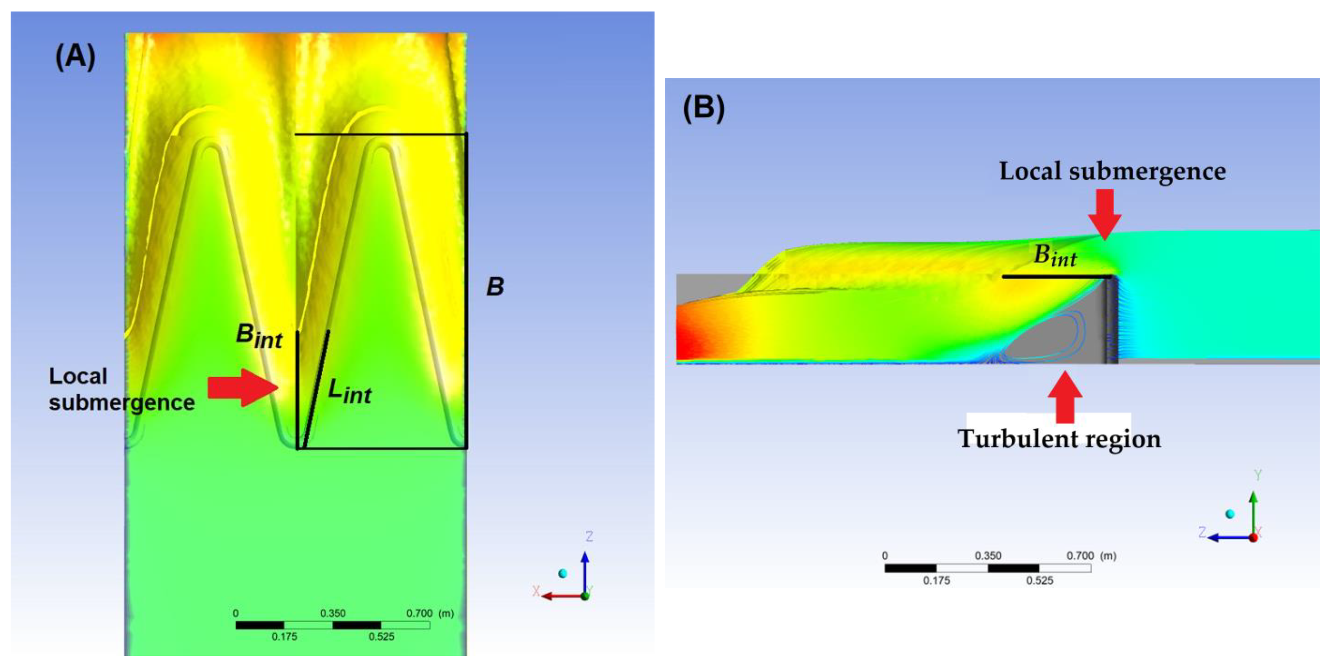
1.1.3. Nappe Interference
1.1.4. Drowning
2. Materials and Methods
2.1. Description of the Physical Model
2.2. Numerical Solution Method
2.2.1. Computational Fluid Dynamics (CFD)
2.2.2. Grid Convergence Index (GCI)
2.3. Evaluation of the Computational Model
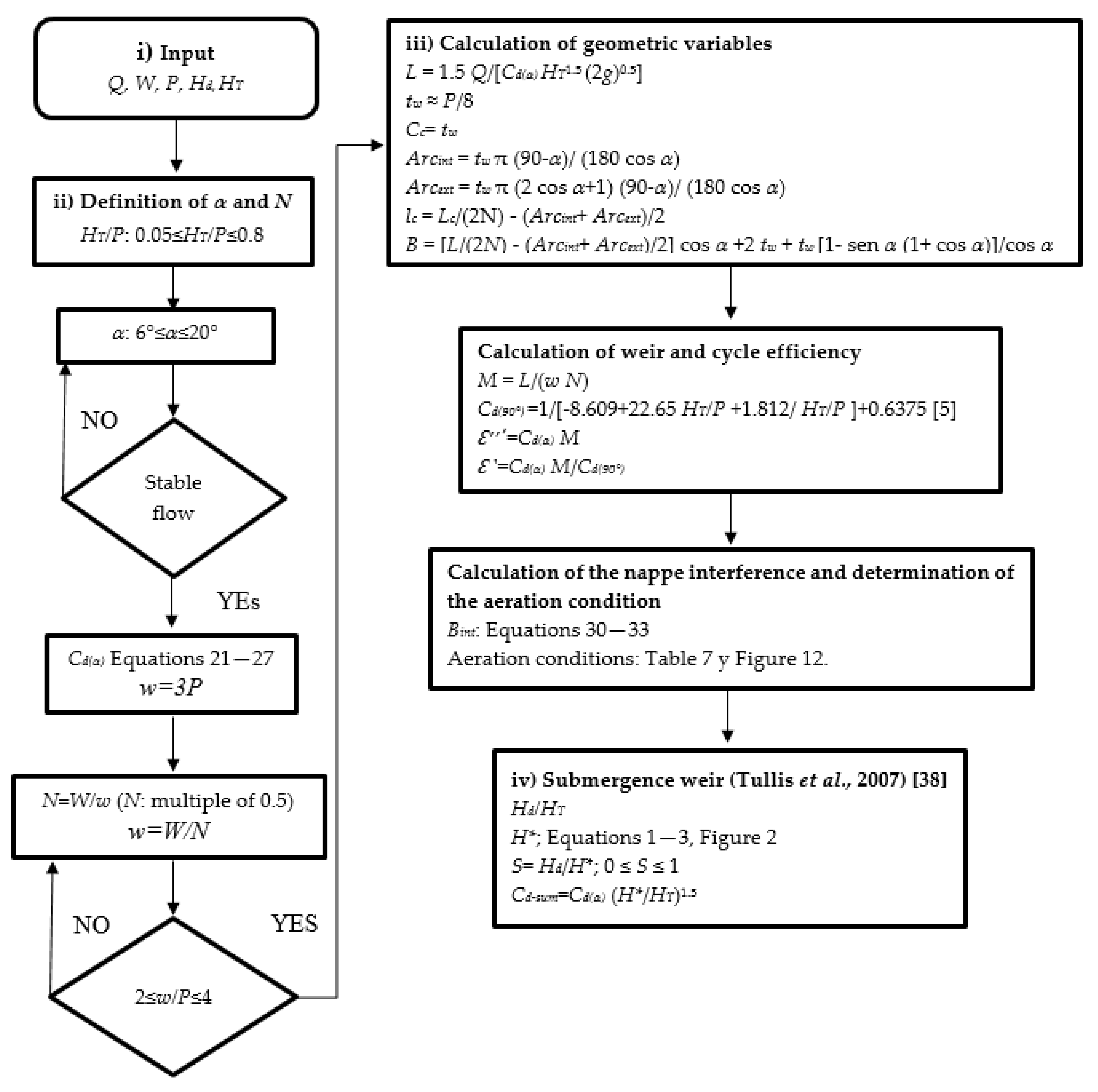
2.4. Proposed Sequential Design Method for a Labyrinth Weir
- (a)
- The design flow (Q), which represents the design discharge for a given return period;
- (b)
- The upstream head of the weir (HT), which depends on the channel width (W) and is limited by the freeboard;
- (c)
- The downstream head of the weir (Hd) is calculated from the drop height and the flow velocity at the foot of the weir;
- (d)
- The weir height (P) corresponds to the height of the storage volume or the Ordinary Maximum Water Level obtained from the topography and the operation of the basin.
- The length of the weir (L). The selection of the angle α will determine the length of the weir. Its calculation is a function of the discharge coefficient, the hydraulic head, and the design flow.
- The width of the weir wall (tw) and the internal apex rope (Cc) must both be equal to P/8.
- The internal and external apex arc (Arcint, Arcext) are both functions of tw and α.
- The length of the cycle wall (lc), as a function of L, N, Arcint, and Arcext.
- The length of the platform (B) is a function of L, N, Arcint, Arcext, α, and tw.
3. Results
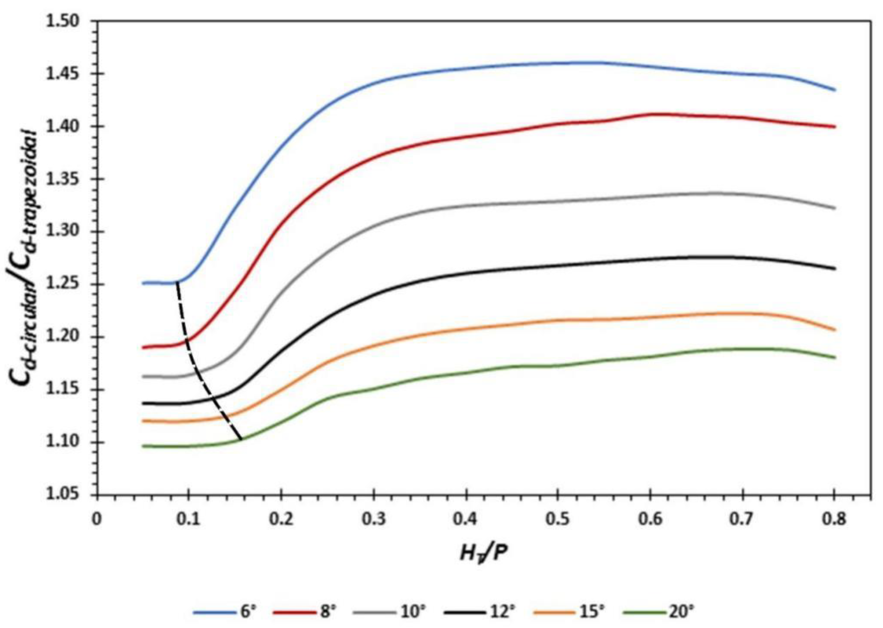
3.1. Discharge Coefficient, Weir, and Cycle Efficiency
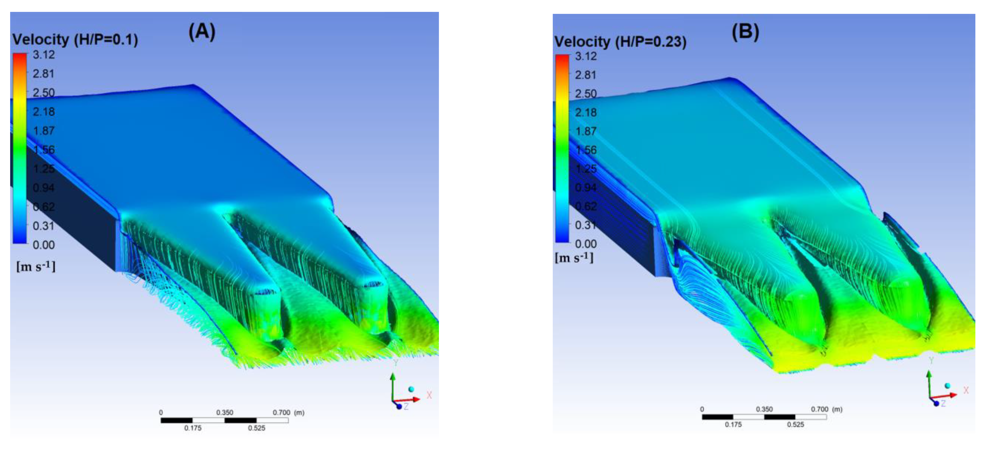
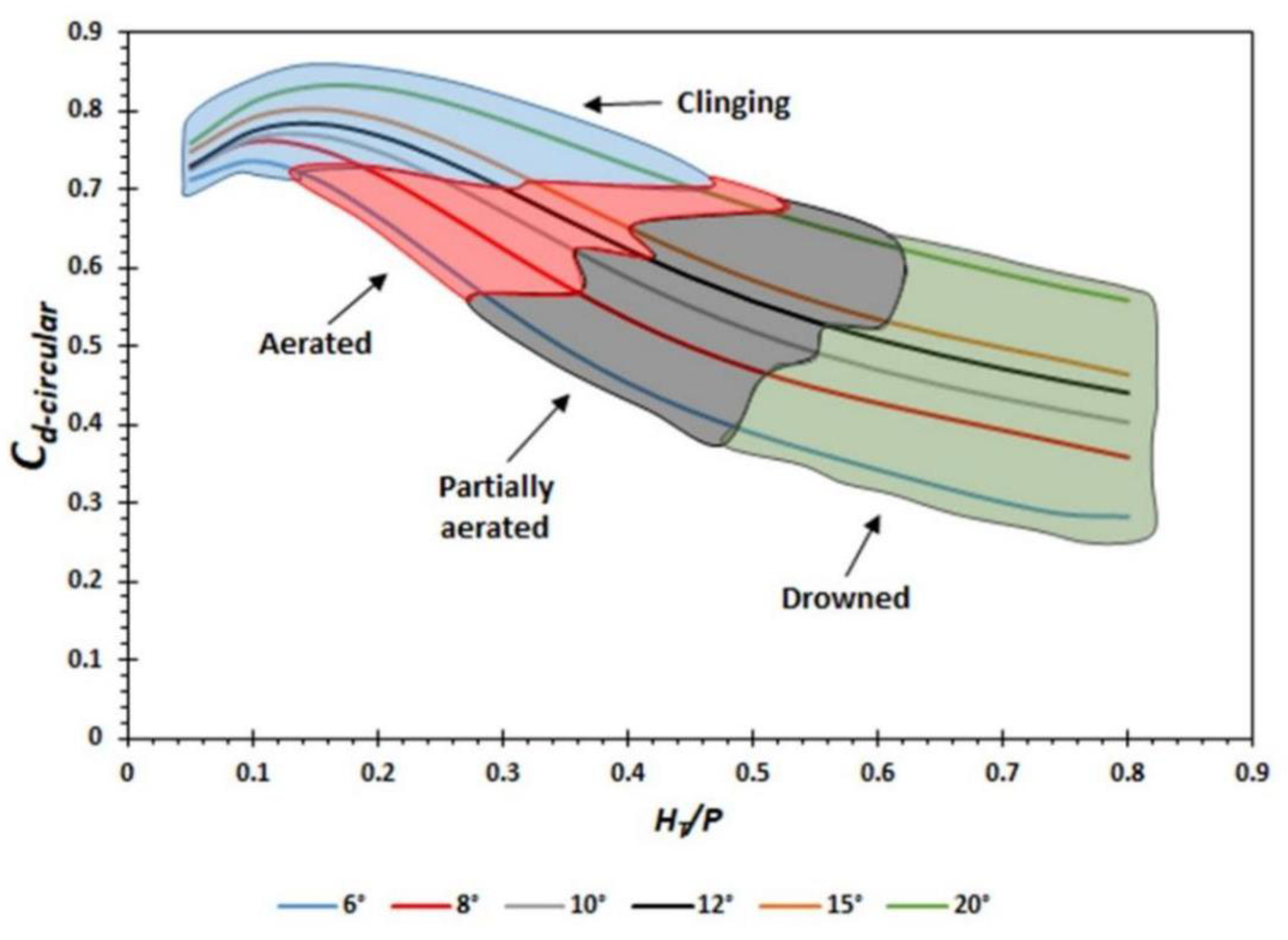
3.2. Nappe Aeration Conditions
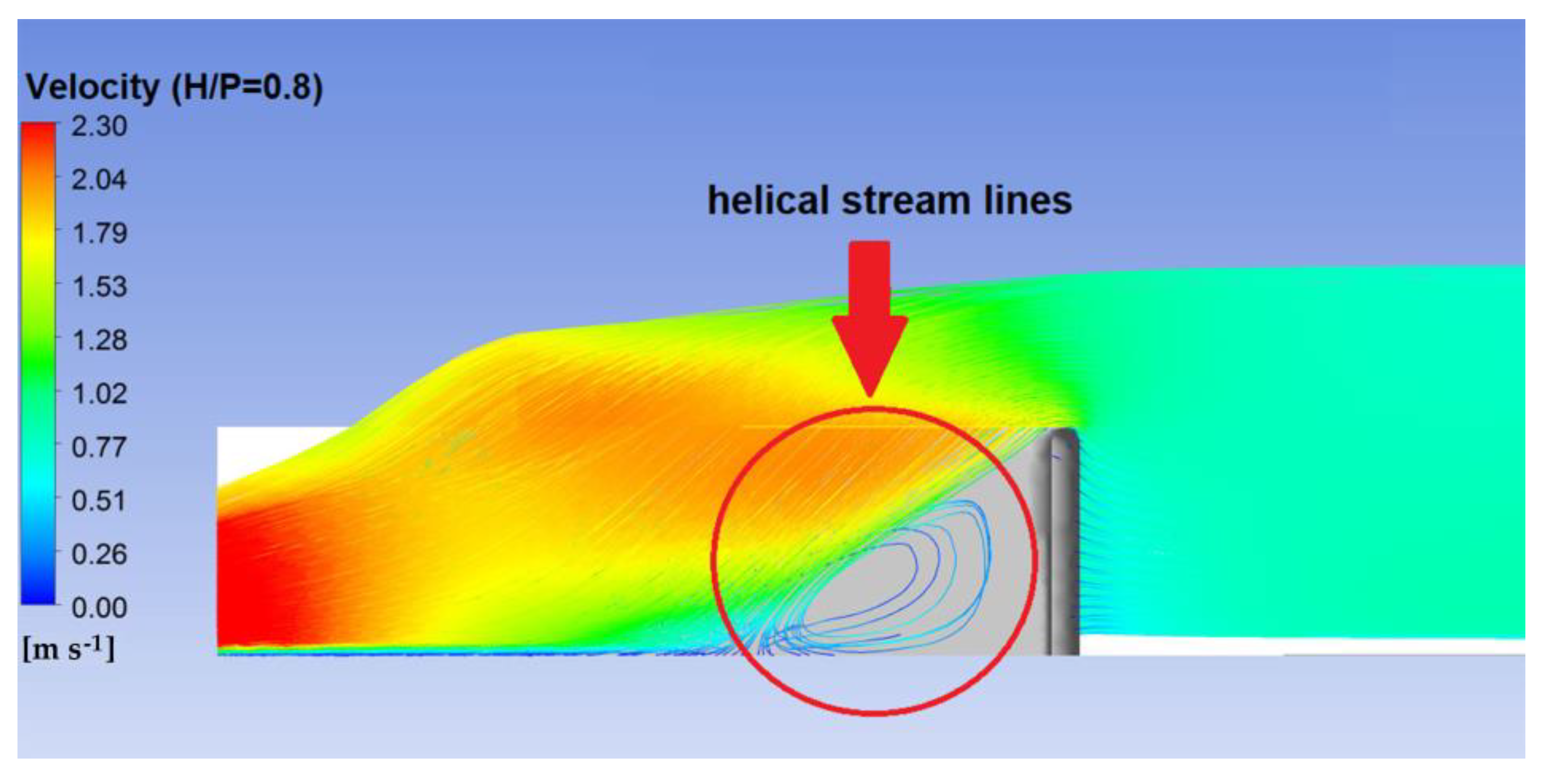
3.3. Nappe Instability
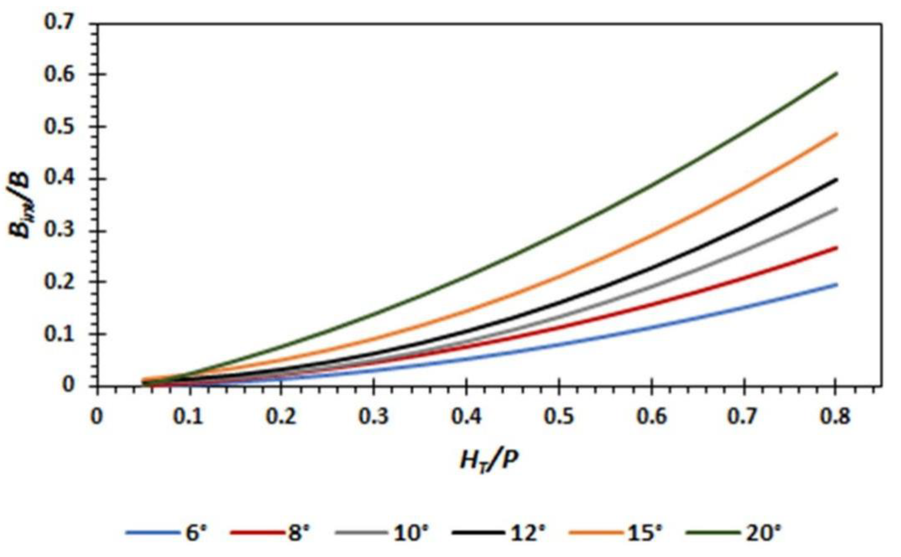
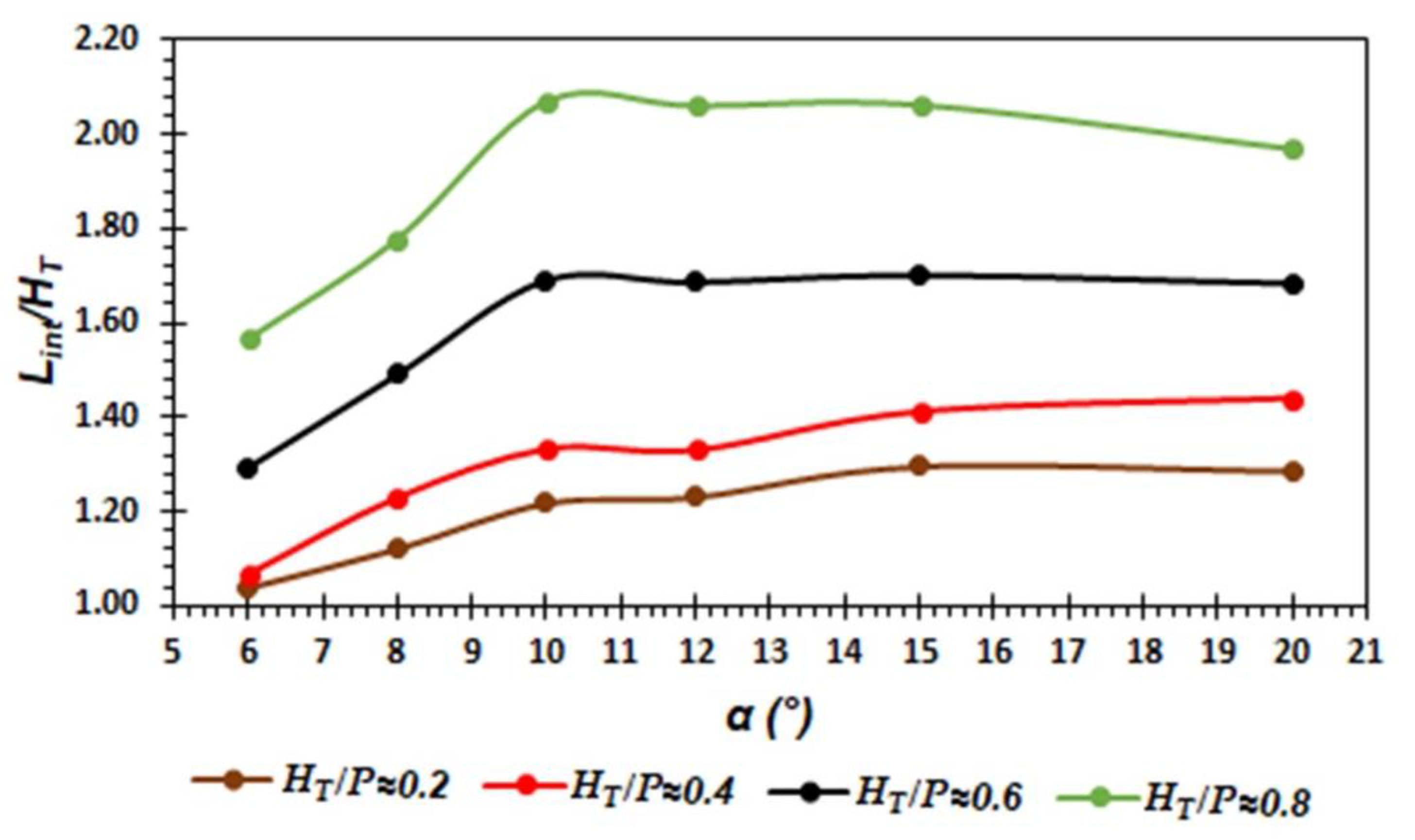
3.4. Nappe Interference
3.5. Application of the Proposed Method
4. Discussion
4.1. Discussion of Discharge Coefficient, Weir, and Cycle Efficiency
4.2. Discussion of Nappe Aeration Conditions
4.3. Discussion of Nappe Instability and Interference
4.4. Discussion of Application of the Proposed Method
5. Conclusions
Author Contributions
Funding
Data Availability Statement
Conflicts of Interest
Abbreviations
| A | internal length apex. |
| Arcint | internal apex arc. |
| Arcext | external apex arc. |
| Ax, Ay, Az | fractional area in the x, y, z direction, respectively. |
| a | adjustment factor to obtain the discharge coefficient. |
| B | length of apron. |
| Bint | nappe interference length. |
| b | adjustment factor to obtain the discharge coefficient. |
| c | adjustment factor to obtain the discharge coefficient. |
| Cd | discharge coefficient. |
| Cd-sum | submerged weir discharge coefficient. |
| Cd(α) | labyrinth weir discharge coefficient |
| Cd(90°) | linear weir discharge coefficient. |
| Cc | internal apex rope. |
| C1Ꜫ, C2Ꜫ, Cμ | constants of the turbulent k-ε model. |
| Cov | covariance. |
| D | external apex length. |
| Dkeff | effective diffusivity for turbulent kinetic energy. |
| Dεeff | effective diffusivity for dissipation rate. |
| d | adjustment factor to obtain the discharge coefficient. |
| e | adjustment factor to obtain the discharge coefficient. |
| FD | diffusion term. |
| FS | source term. |
| Fs | security factor. |
| f | adjustment factor to obtain the discharge coefficient. |
| fi | control variable. |
| fx, fy, fz | viscous acceleration in x, y, z direction, respectively. |
| Gk | turbulent kinetic energy generation due to mean velocity gradients. |
| Gx, Gy, Gz | acceleration of the body in the x, y, z direction, respectively. |
| g | acceleration gravity. |
| Hd | downstream total head. |
| HT | upstream total head. |
| H* | upstream total head of the drowned weir. |
| h | piezometric head. |
| k | turbulent kinetic energy. |
| L | characteristic length of the weir. |
| Lcycle | cycle length. |
| Lint | length of the crest affected by the nappe interference. |
| lC | centerline length of sidewall. |
| M | magnification ratio. |
| m | adjustment coefficient to obtain the length Bint. |
| N | number of cycles. |
| NC | number of cells. |
| n | adjustment coefficient to obtain the length Bint. |
| o | adjustment coefficient to obtain the length Bint. |
| P | weir height. |
| p | order of convergence. |
| Q | design flow. |
| QN | flow of a linear weir. |
| Rcrest | radius of the weir crest. |
| r | mesh refinement ratio. |
| S | submergence level. |
| Sij2 | strain rate tensor. |
| tw | weir wall width. |
| tw−1 | upper crest width. |
| tw−2 | lower crest width. |
| u | velocity component in the x direction. |
| VF | fraction volume. |
| v | velocity component in y direction. |
| vt | turbulent kinematic viscosity. |
| W | channel width. |
| w | cycle width. |
| Yexp | experimental results. |
| Ynum | numerical results. |
| z | velocity component in z direction. |
| α | angle of sidewall. |
| ∆Vi | volume of the i-th cell. |
| γ | representative cell size. |
| ε | dissipation rate. |
| ε | relative error. |
| ε′ | weir efficiency. |
| ε″ | cycle efficiency. |
| σ2exp | variance of the experimental results. |
| σ2num | variance of the numerical results. |
| σꜪ | Prandtl number. |
References
- Mattos-Villarroel, E.D.; Flores-Velazquez, J.; Ojeda-Bustamante, W.; Iñiguez-Covarrubias, M.; Díaz-Delgado, C.; Salinas-Tapia, H. Hydraulic analysis of a compound weir (triangular-rectangular) simulated with computational fluid dynamics (CFD). Technol. Cienc. Agua 2021, 12, 112–162. [Google Scholar] [CrossRef]
- Darvas, L.A. Discussion of performance and design of labyrinth weirs, by Hay and Taylor. J. Hydraul. Eng. ASCE 1971, 97, 1246–1251. [Google Scholar] [CrossRef]
- Bilhan, O.; Emiroglu, E.; Miller, C.J. Experimental investigation of discharge capacity of labyrinth weirs with and without nappe breakers. World J. Mech. 2016, 6, 207–221. [Google Scholar] [CrossRef]
- Willmore, C. Hydraulic Characteristics of Labyrinth Weirs. Master’s Thesis, Utah State University, Logan, Utah, April 2004. [Google Scholar]
- Crookston, B. Labyrinth Weirs. Ph.D. Thesis, Utah State University, Logan, Utah, December 2010. [Google Scholar]
- Tullis, B.; Young, J. Lake Brazos Dam Model Study of the Existing Spillway Structure and a New Labyrinth Weir Spillway Structure; Report No. 1575; Utah Water Research Laboratory: Logan, Utah, 2005. [Google Scholar]
- Magalhães, A.; Lorena, M. Hydraulic Design of Labyrinth Weirs; Report No. 736; National Laboratory of Civil Engineering: Lisboa, Portugal, 1989. [Google Scholar]
- Houston, K. Hydraulic Model Study of Hyrum Dam Auxiliary Labyrinth Spillway; Report No. GR-82-13; U.S. Bureau of Reclamation: Denver, Colorado, 1983. [Google Scholar]
- Houston, K. Hydraulic Model Study of Ute Dam Labyrinth Spillway; Report No. GR-82-7; U.S. Bureau of Reclamation: Denver, Colorado, 1982. [Google Scholar]
- Tullis, B.; Crookston, B.M. Lake Townsend Dam Spillway Hydraulic Model Study Report; Utah Water Research Laboratory: Logan, Utah, 2008. [Google Scholar]
- Hay, N.; Taylor, G. Performance and design of labyrinth weirs. J. Hydraul. Div. 1970, 96, 2337–2357. [Google Scholar] [CrossRef]
- Hinchliff, D.; Houston, K. Hydraulic Design and Application of Labyrinth Spillways; Division of Research Engineering and Research Center, Bureau of Reclamation: Denver, Colorado, 1984. [Google Scholar]
- Lux, F., III. Design and application of labyrinth weirs. In Design of Hydraulic Structures 89; Alberson, M.L., Kia, R.A., Eds.; Balkema/Rotterdam/Brookfield: Toronto, ON, Canada, 1989; pp. 205–215. [Google Scholar]
- Tullis, J.P.; Amanian, N.; Waldron, D. Design of labyrinth spillways. J. Hydraul. Eng. 1995, 121, 247–255. [Google Scholar] [CrossRef]
- Crookston, B.M.; Tullis, B.P. Hydraulic design and analysis of labyrinth weirs. I: Discharge relationships. J. Irrig. Drain. Eng. 2012, 139, 363–370. [Google Scholar] [CrossRef]
- Idrees, A.K.; Al-Ameri, R. A review of hydraulic performance and design methods of labyrinth weirs. Water Supp. 2022, 22, 8120–8138. [Google Scholar] [CrossRef]
- Savage, B.; Frizell, K.; Crowder, J. Brains versus brawn: The changing world of hydraulic model studies. In Proceedings of the Annual Conference Association of State Dam Safety Officials (ASDSO), Phoenix, AZ, USA, 26–30 September 2004. [Google Scholar]
- Paxson, G.; Savage, B. Labyrinth spillways: Comparison of two popular USA design methods and consideration of non-standard approach conditions and geometries. In International Junior Researcher and Engineer Workshop on Hydraulic Structures; Report CH61/06; The University of Queensland: Brisbane, Australia, 2006. [Google Scholar]
- Chanel, P.G.; Doering, J.C. Assessment of spillway modeling using computational fluid dynamics. Can. J. Civ. Eng. 2008, 35, 1481–1485. [Google Scholar] [CrossRef]
- Aydin, M.C.; Emiroglu, M.E. Determination of capacity of labyrinth side weir by CFD. Flow Meas. Instrum. 2013, 29, 1–8. [Google Scholar] [CrossRef]
- Savage, B.M.; Crookston, B.M.; Paxson, G.S. Physical and numerical modeling of large headwater ratios for a 15 labyrinth spillway. J. Hydraul. Eng. 2016, 142, 04016046. [Google Scholar] [CrossRef]
- Crookston, B.M.; Anderson, R.M.; Tullis, B.P. Free-flow discharge estimation method for Piano Key weir geometries. J. Hydro-Environ. Res. 2018, 19, 160–167. [Google Scholar] [CrossRef]
- Ben Said, M.; Hafnaoui, M.A.; Madi, M. Numerical analysis of the influence of approach flow conditions on the efficiency of labyrinth weir. Model. Earth Syst. Environ. 2022, 1–11. [Google Scholar] [CrossRef]
- Samadi, A.; Salmasi, F.; Arvanaghi, H.; Mousaviraad, M. Effects of Geometrical Parameters on Labyrinth Weir Hydraulics. J. Irrig. Drain. Eng. 2022, 148, 06022006. [Google Scholar] [CrossRef]
- Lux, F., III; Hinchliff, D. Design and construction of labyrinth spillways. In Proceedings of the 15th International Congress on Large Dams, International Commission on Large Dams, Paris, France, 15–19 November 1985. [Google Scholar]
- Crookston, B.M.; Tullis, B.P. Labyrinth weirs: Nappe interference and local submergence. J. Irrig. Drain. Eng. 2012, 138, 757–765. [Google Scholar] [CrossRef]
- Falvey, H.T. Hydraulic Design of Labyrinth Weirs; American Society of Civil Engineers (ASCE): Reston, VA, USA, 2003; pp. 31–108. [Google Scholar] [CrossRef]
- Hauser, G. Design of Aerating Weirs; Report TR-1039472694-17; Electrical Power Research Institute: Palo Alto, CA, USA, 1996. [Google Scholar]
- Wormleaton, P.R.; Soufiani, E. Aeration performance of triangular planform labyrinth weirs. J. Environ. Eng. 1998, 124, 709–719. [Google Scholar] [CrossRef]
- Wormleaton, P.R.; Tsang, C.C. Aeration performance of rectangular planform labyrinth weirs. J. Environ. Eng. 2000, 126, 456–465. [Google Scholar] [CrossRef]
- Casperson, L.W. Fluttering fountains. J. Sound Vib. 1995, 162, 251–262. [Google Scholar] [CrossRef]
- Naudascher, E.; Rockwell, D. Flow Induced Vibrations. An Engineering Guide; Dover Publications: Mineola, NY, USA, 1994; pp. 90–176. [Google Scholar]
- Yildiz, D.; Uzucek, E. Modeling the performance of labyrinth spillways. Int. J. Hydropower Dams 1996, 3, 71–76. [Google Scholar]
- Metropolitan Water, Sewerage and Drainage Board. Investigations into Spillway Discharge Noise at Avon Dam; Bulletin No. 57; ANCOLD: Sydney, NSW, Austria, 1980. [Google Scholar]
- Indlekofer, H.; Rouvé, G. Discharge over polygonal weirs. J. Hydraul. Div. 1975, 101, 385–401. [Google Scholar] [CrossRef]
- Osuna, A. Determinación del desagüe en un vertedor oblicuo. Rev. Obras Públicas 2000, 147, 3402. [Google Scholar]
- Granel, C.; Toledo, M. Los aliviaderos tipo laberinto. Un nuevo enfoque para su cálculo hidráulico. In Proceedings of the II International Congress on Dam Maitenance and Rehabilitation, Zaragoza, España, 23–25 November 2010. [Google Scholar]
- Tullis, B.P.; Young, J.C.; Chandler, M.A. Head-discharge relationships for submerged labyrinth weirs. J. Hydraul. Eng. 2007, 133, 248–254. [Google Scholar] [CrossRef]
- Taylor, G. The Performance of Labyrinth Weirs. Ph.D. Thesis, University of Nottingham, Nottingham, UK, 1968. [Google Scholar]
- Villemonte, J.R. Submerged weir discharge studies. Eng. News-Rec. 1947, 139, 54–56. [Google Scholar]
- Yildiz, A.; Marti, A.I.; Gogus, M. Determination of hydraulic characteristics of flow over a triangular sectioned weir by using experimental and numerical modeling. J. Comput. Appl. Mech. 2021, 52, 215–232. [Google Scholar] [CrossRef]
- Mattos-Villarroel, E.; Flores-Velázquez, J.; Ojeda-Bustamante, W.; Díaz-Delgado, C.; Salinas-Tapia, H. Influence of crest geometric on discharge coefficient efficiency of labyrinth weirs. Flow Meas. Instrum. 2021, 81, 102031. [Google Scholar] [CrossRef]
- Bilhan, O.; Aydin, M.C.; Emiroglu, M.E.; Miller, C.J. Experimental and CFD analysis of circular labyrinth weirs. J. Irrig. Drain. Eng. 2018, 144, 04018007. [Google Scholar] [CrossRef]
- Hirt, C.W.; Nichols, B.D. Volume of fluid (VOF) method for the dynamics of free boundaries. J. Comput. Phys. 1981, 39, 201–225. [Google Scholar] [CrossRef]
- Olsen, N.R.; Nils, R.B.; KJellesvig, H.M. Three-dimensional numerical flow modeling for estimation of spillway capacity. J. Hydr. Res. 1998, 36, 775–784. [Google Scholar] [CrossRef]
- San Mauro, J.; Salazar, F.; Toledo, M.A.; Caballero, F.J.; Ponce-Farfán, C.; Ramos, T. Physical and numerical modeling of labyrinth weirs with polyhedral bottom. Ing. Agua 2016, 20, 127–138. [Google Scholar] [CrossRef]
- Jiang, L.; Diao, M.; Sun, H.; Ren, Y. Numerical Modeling of Flow over a Rectangular Broad-Crested Weir with a Sloped Upstream Face. Water 2018, 10, 1663. [Google Scholar] [CrossRef]
- Shaheed, R.; Mohammadian, A.; Gildeh, H.K. A comparison of standard k–ε and realizable k–ε turbulence models in curved and confluent channels. Environ. Fluid Mech. 2019, 19, 543–568. [Google Scholar] [CrossRef]
- Fernández, J.M. Técnicas numéricas en Ingeniería de Fluidos: Introducción a la Dinámica de Fluidos Computacional (CFD) por el Método de Volumen Finito, 1st ed.; Reverté: Barcelona, España, 2012; pp. 98–294. [Google Scholar]
- Carrillo, J.M.; Castillo, L.G. Consideraciones del mallado aplicadas al cálculo de flujos bifásicos con las técnicas de dinámica de fluidos computacional. J. Introd. Investig. UPCT 2011, 4, 33–35. [Google Scholar]
- Celik, I.B.; Ghia, U.; Roache, P.J.; Freitas, C.J.; Coleman, H.; Raad, P.E. Procedure for estimation and reporting of uncertainty due to discretization in CFD applications. J. Fluids Eng.-ASME 2008, 130, 7. [Google Scholar] [CrossRef]
- Roache, P.J. Perspective: A method for uniform reporting of grid refinement studies. J. Fluids Eng. 1994, 116, 405–413. [Google Scholar] [CrossRef]
- Baker, N.; Kelly, G.; O’Sullivan, P.D. A grid convergence index study of mesh style effect on the accuracy of the numerical results for an indoor airflow profile. Int. J. Vent. 2020, 19, 300–314. [Google Scholar] [CrossRef]
- Liu, H.L.; Liu, M.M.; Bai, Y.; Dong, L. Effects of mesh style and grid convergence on numerical simulation accuracy of centrifugal pump. J. Cent. South Univ. 2015, 22, 368–376. [Google Scholar] [CrossRef]
- Examining Spatial (Grid) Convergence. Available online: https://www.grc.nasa.gov/www/wind/valid/tutorial/spatconv.html (accessed on 4 November 2021).
- Roache, P.J. Quantification of uncertainty in computational fluid dynamics. Ann. Rev. Fluid Mech. 1997, 29, 123–160. [Google Scholar] [CrossRef] [Green Version]
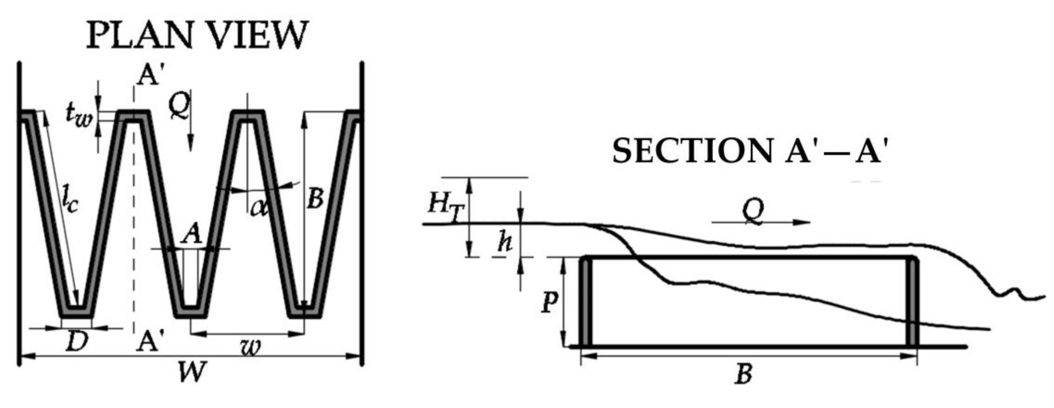

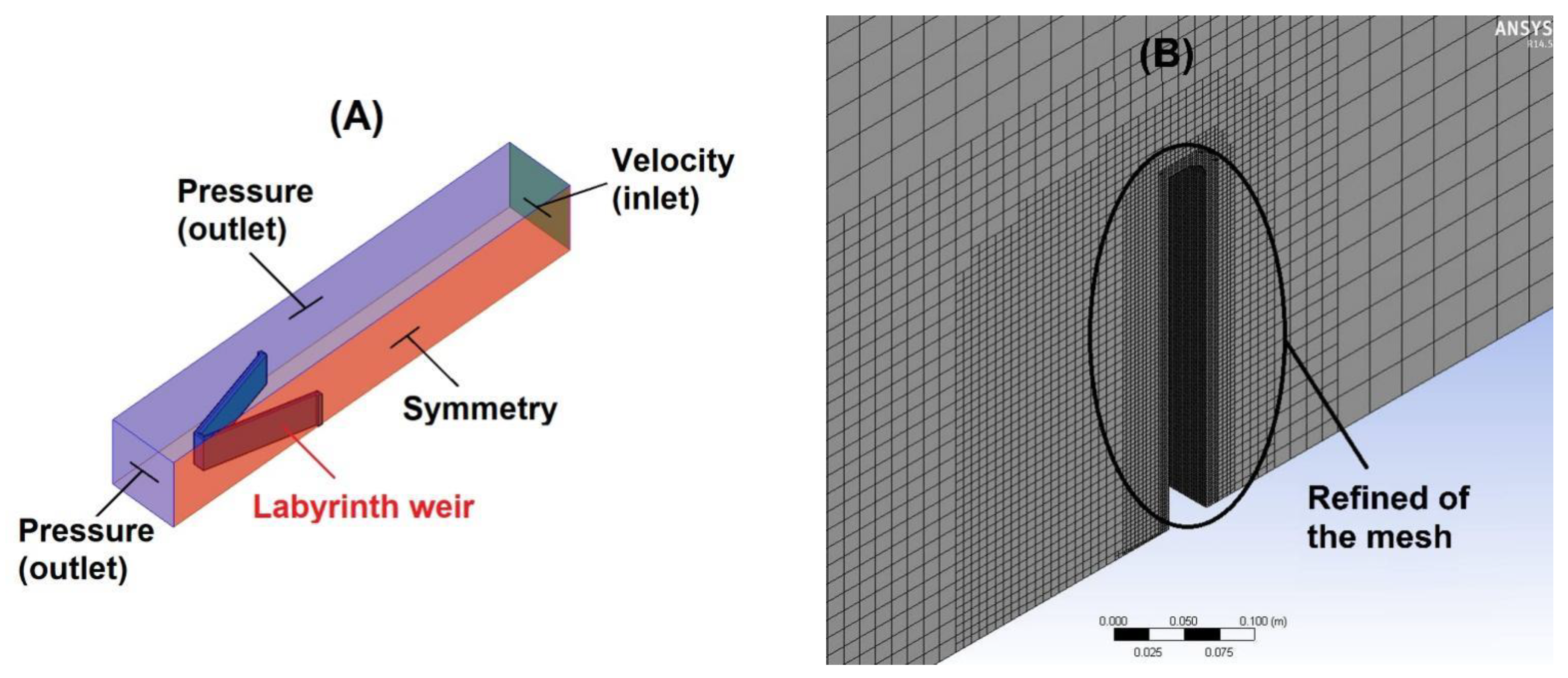


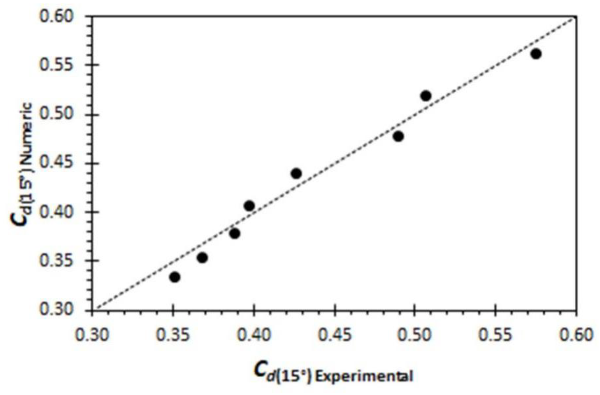
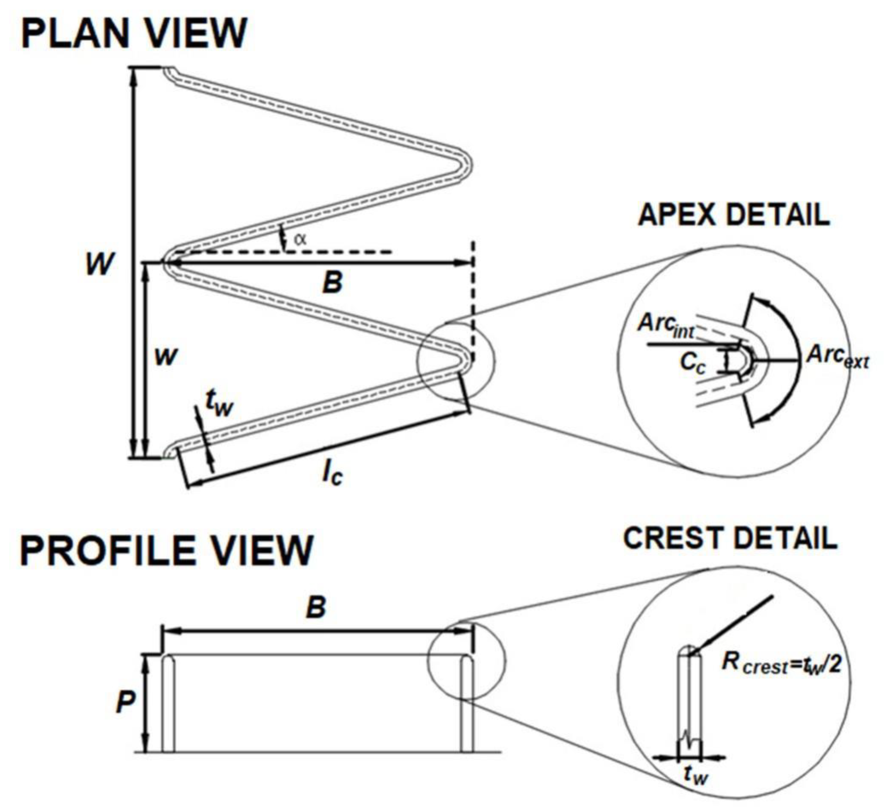






| α (°) | N | L (m) | A (m) | w (m) | P (m) | W (m) | Crest Profile |
|---|---|---|---|---|---|---|---|
| 15 | 2 | 4 | 0.038 | 0.617 | 0.305 | 1.235 | Quarter-round |
| Boundary and Initial Conditions | Solution Method |
|---|---|
| Domain: inlet | Velocity |
| Domain: outlet | Atmospheric pressure |
| Domain: weir, sidewalls, and channel platform | Solid, stationary, and non-slip. |
| Viscosity model | k–ε standard |
| Multiphasic model | Volume of fluid (VOF) |
| Pressure–velocity coupling | SIMPLE |
| Spatial discretization scheme | Upwind |
| Grid | Scenario | Grid | Scenario |
|---|---|---|---|
| I | 1–10 | V | 26–30 |
| II | 11–15 | VI | 31–35 |
| III | 16–20 | VII | 36–40 |
| IV | 21–25 |
| Grid | r | p | h1 (m) | h2 (m) | h3 (m) | Richardson Extrapolate (m) | Ꜫ21 | Ꜫ32 | GCI21 (%) | GCI32 (%) | Asymptotic Range of Convergence |
|---|---|---|---|---|---|---|---|---|---|---|---|
| I | 1.60 | 1.80 | 0.1622 | 0.1637 | 0.1672 | 0.1611 | 0.0092 | 0.0214 | 0.87 | 2.00 | 0.99 |
| II | 1.58 | 1.78 | 0.1182 | 0.1197 | 0.1231 | 0.1170 | 0.0127 | 0.0284 | 1.25 | 2.80 | 0.99 |
| III | 1.58 | 1.83 | 0.1302 | 0.1312 | 0.1335 | 0.1294 | 0.0077 | 0.0175 | 0.74 | 1.69 | 0.99 |
| IV | 1.59 | 1.76 | 0.1412 | 0.1423 | 0.1448 | 0.1403 | 0.0078 | 0.0176 | 0.77 | 1.73 | 0.99 |
| V | 1.65 | 1.79 | 0.1482 | 0.1495 | 0.1527 | 0.1473 | 0.0088 | 0.0214 | 0.75 | 1.83 | 0.99 |
| VI | 1.58 | 1.97 | 0.1502 | 0.1519 | 0.1561 | 0.1490 | 0.0113 | 0.0276 | 0.96 | 2.35 | 0.99 |
| VII | 1.64 | 1.89 | 0.1622 | 0.1631 | 0.1654 | 0.1616 | 0.0055 | 0.0141 | 0.45 | 1.13 | 0.99 |
| Scenario | α (°) | P (m) | Lcycle (m) | w/P | N | Q (m3 s−1) | Crest Profile | Apex Shape |
|---|---|---|---|---|---|---|---|---|
| 1, 2, 3, 4, 5, 6, 7, 8, 9, 10 | 15 | 0.305 | 2.00 | 2.024 | 1 | 0.0190, 0.0532, 0.0919, 0.1309, 0.1681, 0.2036, 0.2373, 0.2697, 0.3013, 0.3325 | CR | Trapezoidal |
| 11, 12, 13, 14, 15 | 6 | 0.305 | 3.64 | 2.024 | 1 | 0.0780, 0.1240, 0.2003, 0.2703, 0.3558 | MR | Circular |
| 16, 17, 18, 19, 20 | 8 | 0.305 | 3.07 | 2.024 | 1 | 0.0429, 0.0750, 0.2137, 0.2873, 0.3744 | MR | Circular |
| 21, 21, 23, 24, 25 | 10 | 0.305 | 2.65 | 2.024 | 1 | 0.0367, 0.0532, 0.2170, 0.2891, 0.3712 | MR | Circular |
| 26, 27, 28, 29, 30 | 12 | 0.305 | 2.33 | 2.024 | 1 | 0.0380, 0.0671, 0.1450, 0.2149, 0.3728 | MR | Circular |
| 31, 32, 33, 34, 35 | 15 | 0.305 | 2.02 | 2.024 | 1 | 0.0532, 0.1308, 0.2036, 0.2697, 0.3325 | MR | Circular |
| 36, 37, 38, 39, 40 | 20 | 0.305 | 1.59 | 2.024 | 1 | 0.0290, 0.0517, 0.1247, 0.1915, 0.3364 | MR | Circular |
| HT/P | ||
|---|---|---|
| 6° | 0.10 | 0.736 |
| 8° | 0.11 | 0.762 |
| 10° | 0.13 | 0.771 |
| 12° | 0.14 | 0.784 |
| 15° | 0.15 | 0.803 |
| 20° | 0.17 | 0.833 |
| HT/P | ||||
|---|---|---|---|---|
| Flow Clinging | Flow Aerated | Flow Partially Aerated | Flow Drowned | |
| 6° | <0.165 | 0.165–0.270 | 0.270–0.487 | >0.487 |
| 8° | <0.200 | 0.200–0.350 | 0.350–0.500 | >0.500 |
| 10° | <0.265 | 0.265–0.350 | 0.350–0.540 | >0.540 |
| 12° | <0.300 | 0.300–0.410 | 0.410–0.550 | >0.550 |
| 15° | <0.325 | 0.325–0.400 | 0.400–0.600 | >0.600 |
| 20° | <0.450 | 0.450–0.500 | 0.500–0.600 | >0.600 |
| Instability | Aeration Condition | |
|---|---|---|
| 6° | - | - |
| 8° | - | - |
| 10° | - | - |
| 12° | 0.56 ≤ HT/P ≤ 0.8 | Drowned. |
| 15° | 0.49 ≤ HT/P ≤ 0.8 | Partially aerated, and drowned. |
| 20° | 0.40 ≤ HT/P ≤ 0.8 | Clinging, aerated, partially aerated, and drowned. |
| Concept | Symbol | Value-Unit | Observations |
|---|---|---|---|
| (i) Initial data | |||
| Design flow | Q | 15,574 m3/s | Initially, the design discharge was 16,042 m3/s. |
| Weir width | W | 256 m | - |
| Weir height | P | 9.14 m | - |
| Upstream total head | HT | 5.79 m | - |
| (ii) Geometric variables and non-dimensional relationships | |||
| Head water ratio | HT/P | 0.63 | 0.05 ≤ HT/P ≤ 1 (upper range is expanded from 0.5 to 1 to use the design curves) |
| Flow magnification | Q/QN | 2.4 | - |
| Angle of sidewall | 12.1475° | - | |
| Length magnification | L/W | 4 | 2 ≤ L/W ≤ 8. |
| Vertical aspect ratio | w/P | 2 | 2 ≤ w/P ≤ 5 |
| Cycle width | w | 18.29 m | - |
| Number of cycles | N | 14 | - |
| Weir length | L | 1024.24 m | - |
| Sidewall length | lc | 34.76 m | - |
| Length between apexes | B | 33.99 m | - |
| Apex | A | 1.82 m | - |
| Crest radius | RCrest | 0.30 | - |
| Upper crest width | tw−1 | 0.61 m | - |
| Lower crest width | tw−2 | 1.52 m | - |
| Concept | Symbol | Value-Unit | Equations and Limits |
|---|---|---|---|
| (i) Input data | |||
| Design flow | Q | 15,574 m3/s | - |
| Weir width | W | 256 m | - |
| Weir height | P | 9.14 m | - |
| Upstream total head | HT | 5.79 m | - |
| (ii) Definition of α and the number of cycles (N) | |||
| Head water ratio | HT/P | 0.63 | 0.05 ≤ HT/P ≤ 0.8 |
| Angle of sidewall | 11.5° | 6°≤ α ≤ 20° | |
| Nappe stability | - | Stable | Stable/Unstable: Table 8 and Figure 14 |
| Labyrinth weir discharge coefficient | 0.483 | Equations (21)–(27) | |
| Cycle width | w | 27.42 m | w = 3P |
| Number of cycles | N | 9 | N = W/w |
| New cycle width | w | 28.44 m | w = W/N |
| Vertical aspect ratio | w/P | 3.11 | 2 ≤ w/P ≤ 4 |
| (iii) Calculation of geometric variables, weir and cycle efficiencies, nappe interference and aeration condition | |||
| Geometric variables | |||
| Total centerline length of weir | L | 783.20 m | |
| Wall width | tw | 1.14 m | tw ≈ P/8 |
| Internal apex rope | Cc | 1.14 m | Cc = tw |
| Internal apex arc | Arcint | 1.60 m | |
| External apex arc | Arcext | 1.16 m | − α)/(180 cos α) |
| Centerline length of sidewall | lc | 42.14 m | |
| Length of apron | B | 44.28 m | (or input data) |
| Weir and cycle efficiency | |||
| Magnification ratio | M | 3.17 | |
| Linear weir coefficient discharge | Cd(90°) | 0.754 | [5] |
| Cycle efficiency | 0.74 | ||
| Weir efficiency | 1.96 | ||
| Nappe interference length and aeration condition | |||
| Nappe interference length | Bint | 10.89 m | Equations (30)–(33) |
| Aeration condition | - | Drowned | Table 7 and Figure 12 |
| (iv) Submergence (Tullis et al., 2007 [38]) | |||
| Downstream total head | Hd | 1.22 m | - |
| Head ratio | Hd/HT | 0.21 | - |
| Submergence upstream total head | H* | 5.84 m | Equations (1)–(3) and Figure 2 |
| Submergence level | S | 0.20 | S = Hd/H*; 0 ≤ S ≤ 1 |
| Submerged weir discharge coefficient | 0.476 | ||
Disclaimer/Publisher’s Note: The statements, opinions and data contained in all publications are solely those of the individual author(s) and contributor(s) and not of MDPI and/or the editor(s). MDPI and/or the editor(s) disclaim responsibility for any injury to people or property resulting from any ideas, methods, instructions or products referred to in the content. |
© 2023 by the authors. Licensee MDPI, Basel, Switzerland. This article is an open access article distributed under the terms and conditions of the Creative Commons Attribution (CC BY) license (https://creativecommons.org/licenses/by/4.0/).
Share and Cite
Mattos-Villarroel, E.D.; Ojeda-Bustamante, W.; Díaz-Delgado, C.; Salinas-Tapia, H.; Flores-Velázquez, J.; Bautista Capetillo, C. Methodological Proposal for the Hydraulic Design of Labyrinth Weirs. Water 2023, 15, 722. https://doi.org/10.3390/w15040722
Mattos-Villarroel ED, Ojeda-Bustamante W, Díaz-Delgado C, Salinas-Tapia H, Flores-Velázquez J, Bautista Capetillo C. Methodological Proposal for the Hydraulic Design of Labyrinth Weirs. Water. 2023; 15(4):722. https://doi.org/10.3390/w15040722
Chicago/Turabian StyleMattos-Villarroel, Erick Dante, Waldo Ojeda-Bustamante, Carlos Díaz-Delgado, Humberto Salinas-Tapia, Jorge Flores-Velázquez, and Carlos Bautista Capetillo. 2023. "Methodological Proposal for the Hydraulic Design of Labyrinth Weirs" Water 15, no. 4: 722. https://doi.org/10.3390/w15040722
APA StyleMattos-Villarroel, E. D., Ojeda-Bustamante, W., Díaz-Delgado, C., Salinas-Tapia, H., Flores-Velázquez, J., & Bautista Capetillo, C. (2023). Methodological Proposal for the Hydraulic Design of Labyrinth Weirs. Water, 15(4), 722. https://doi.org/10.3390/w15040722


