


Three-Dimensional Static and Dynamic Analyses of an Embedded Concrete-Face Rockfill Dam


Abstract
:1. Introduction
2. Computational Methods
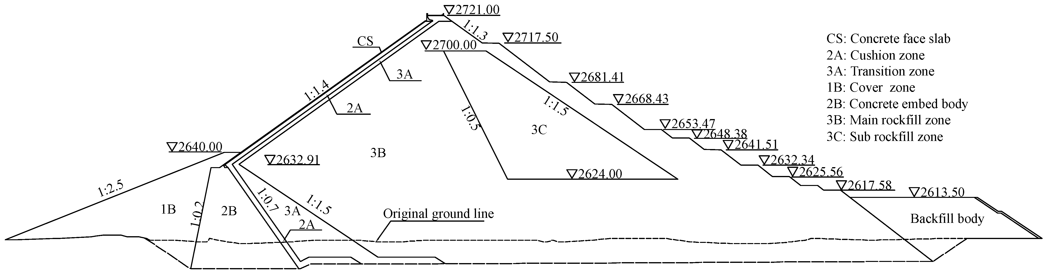
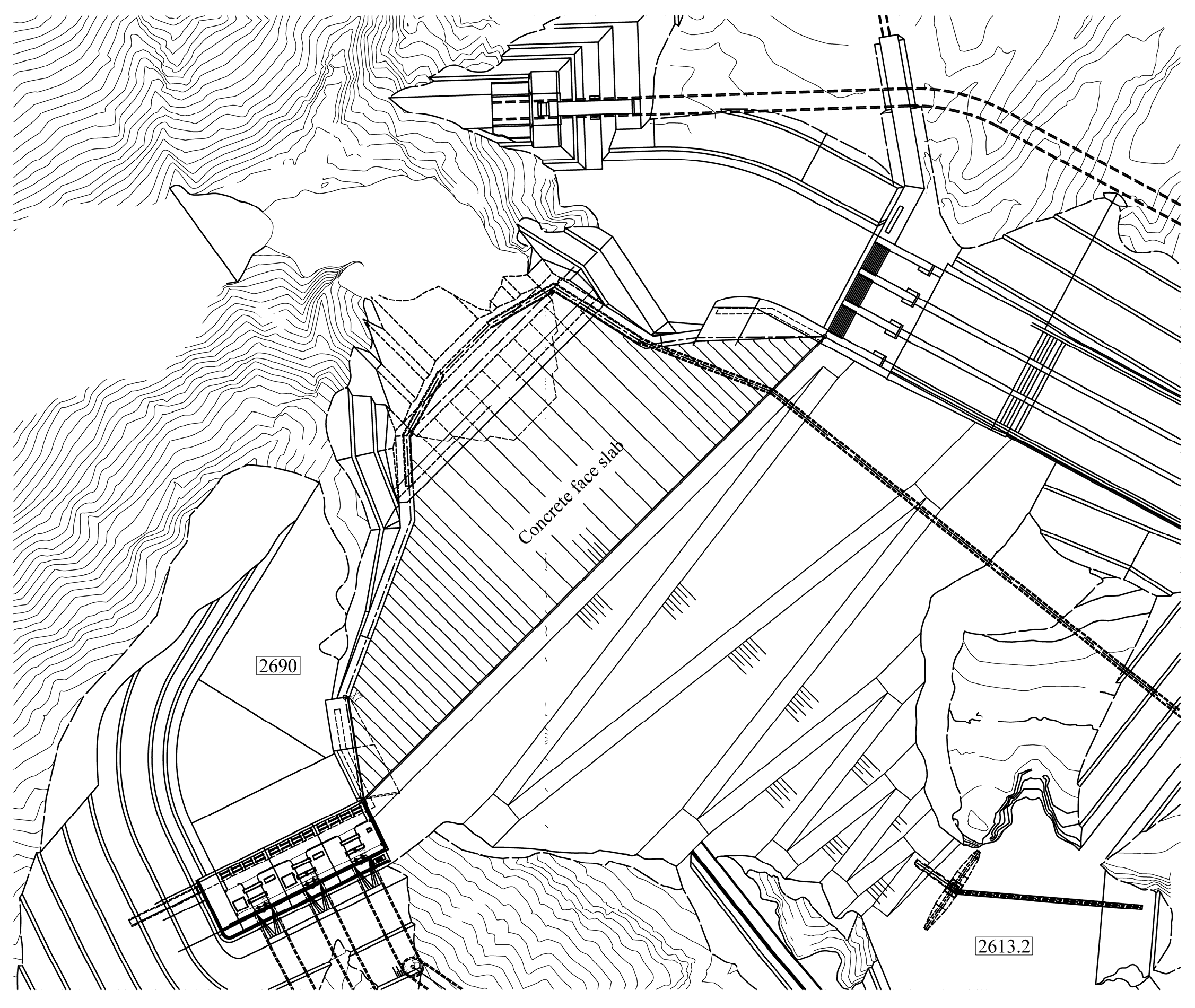
2.1. Project Profile
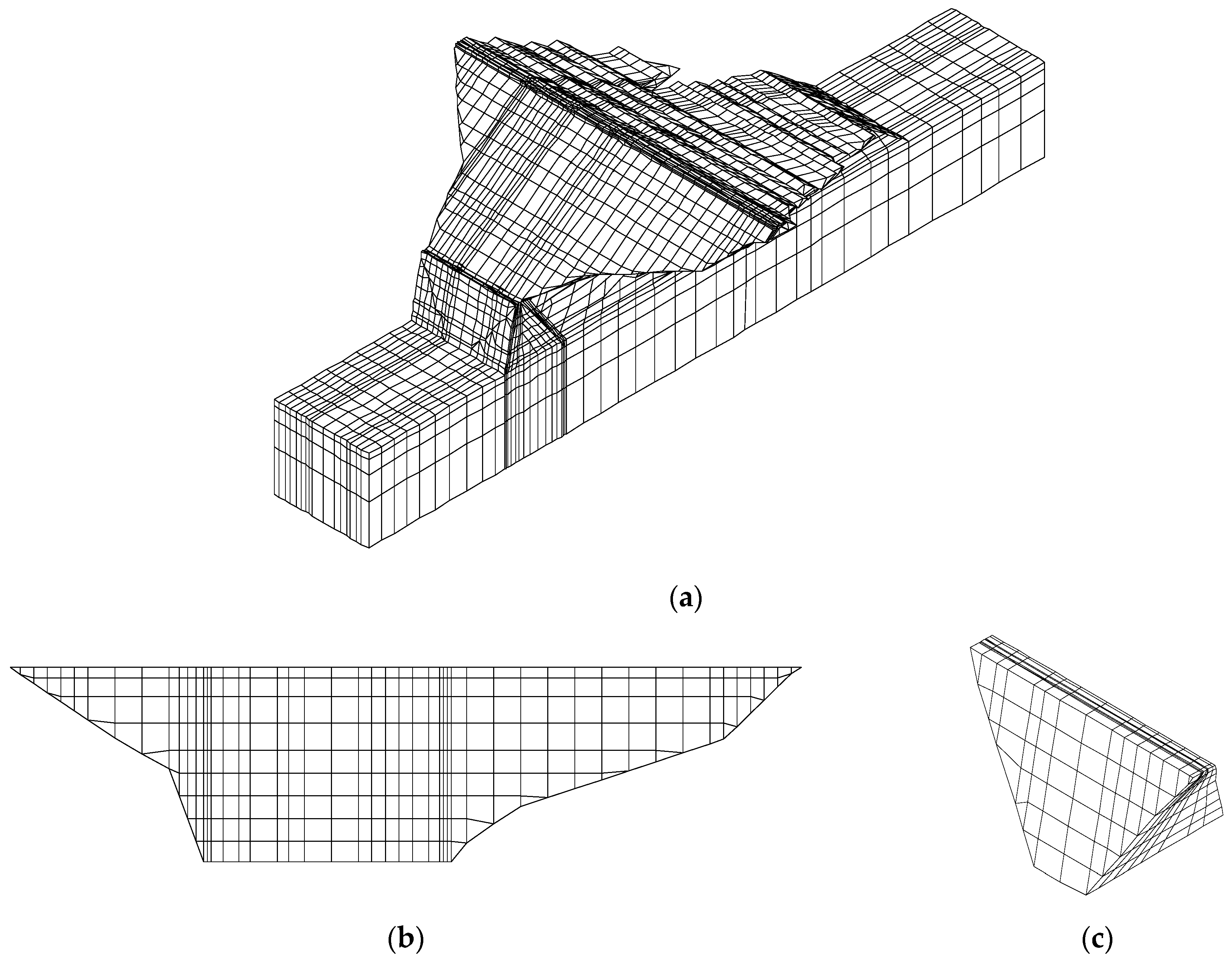
2.2. Finite Element Modelling and Parameters
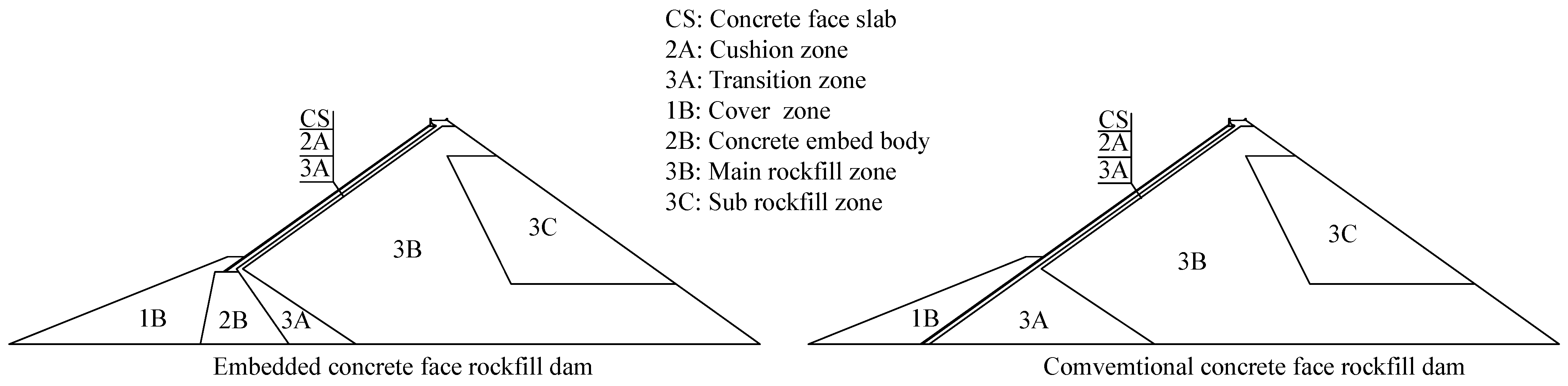
3. Influence of the Embedded Concrete Body on the Static Characteristics of the Dam
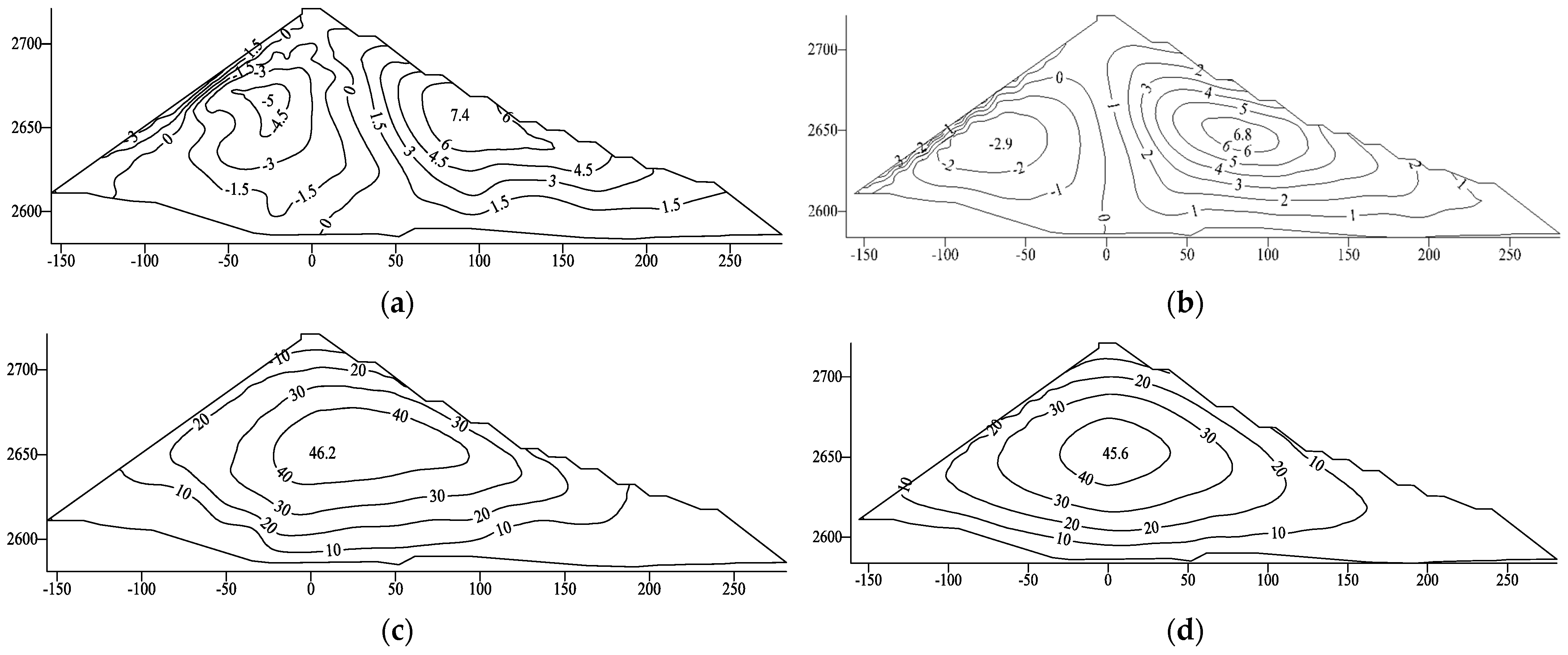
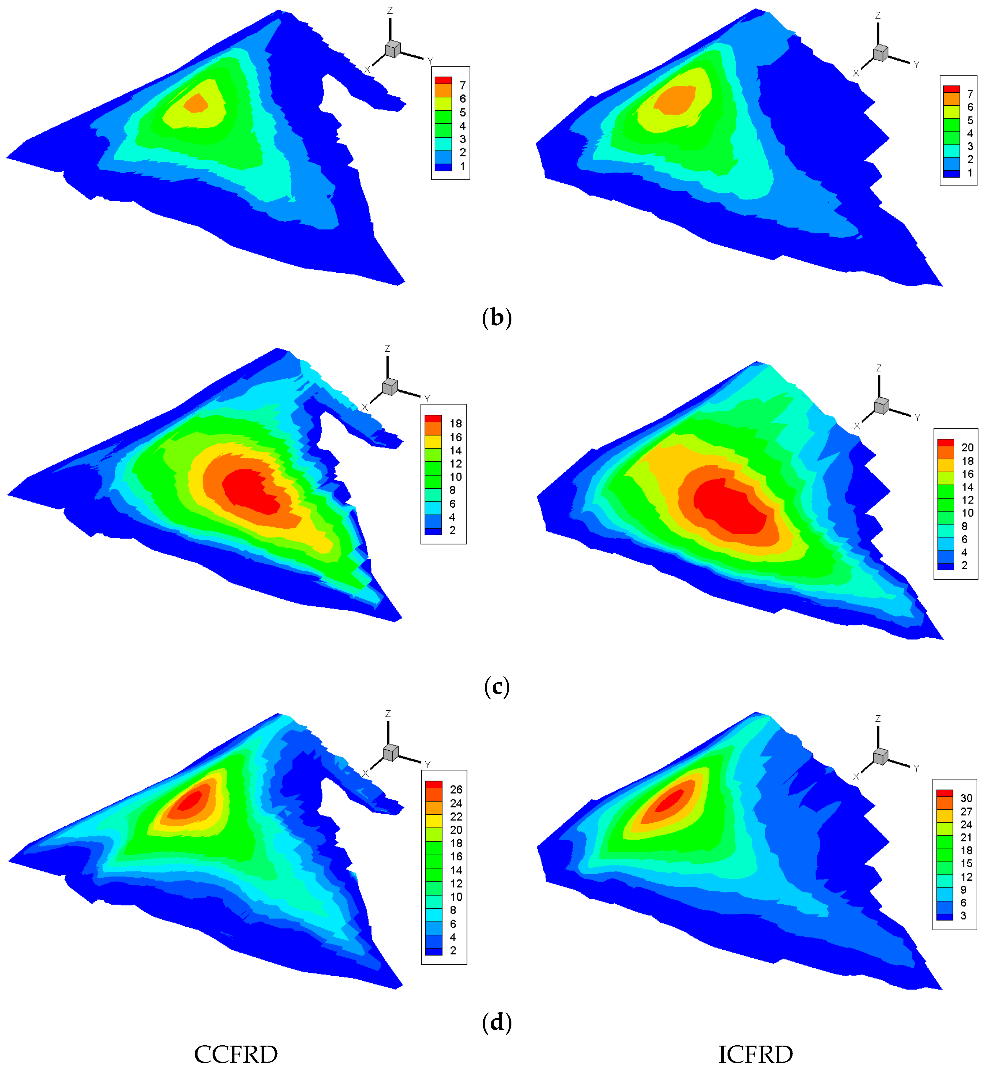
3.1. Rockfill Body Strain Analysis
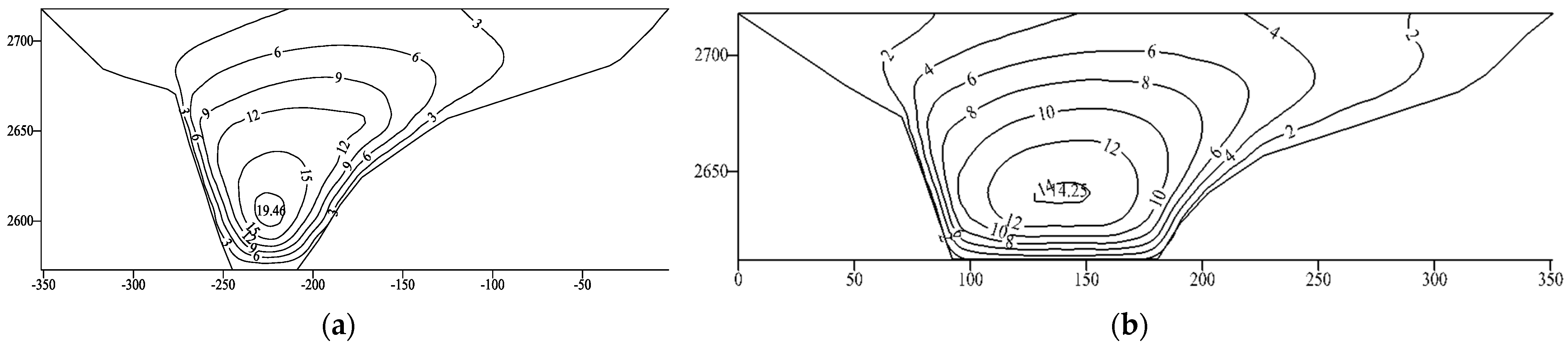
3.2. Concrete-Face Slab Stress–Strain Analysis
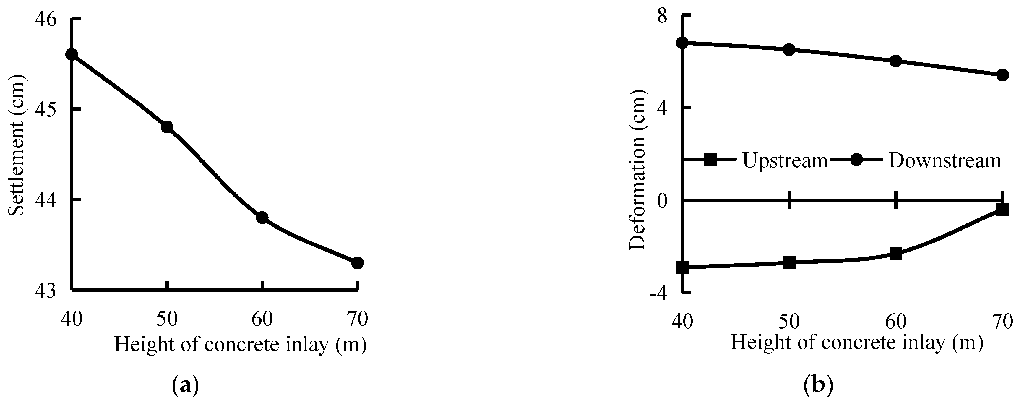
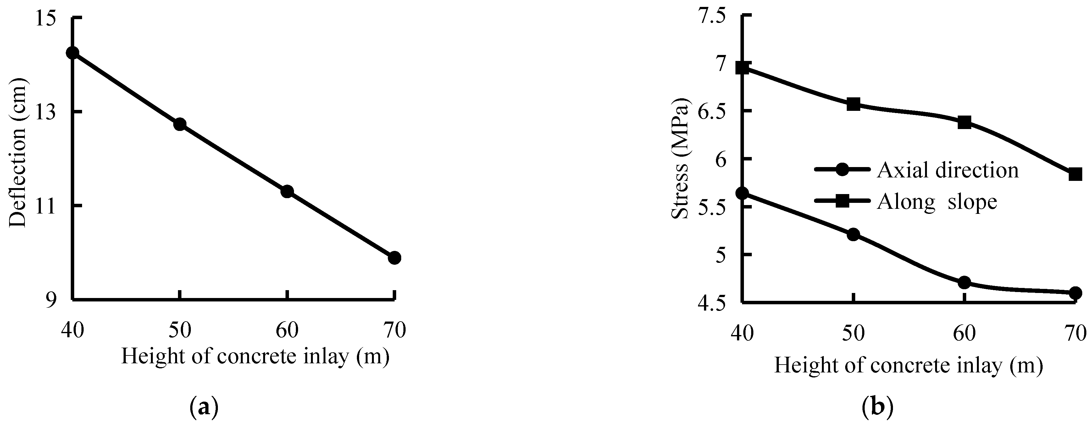
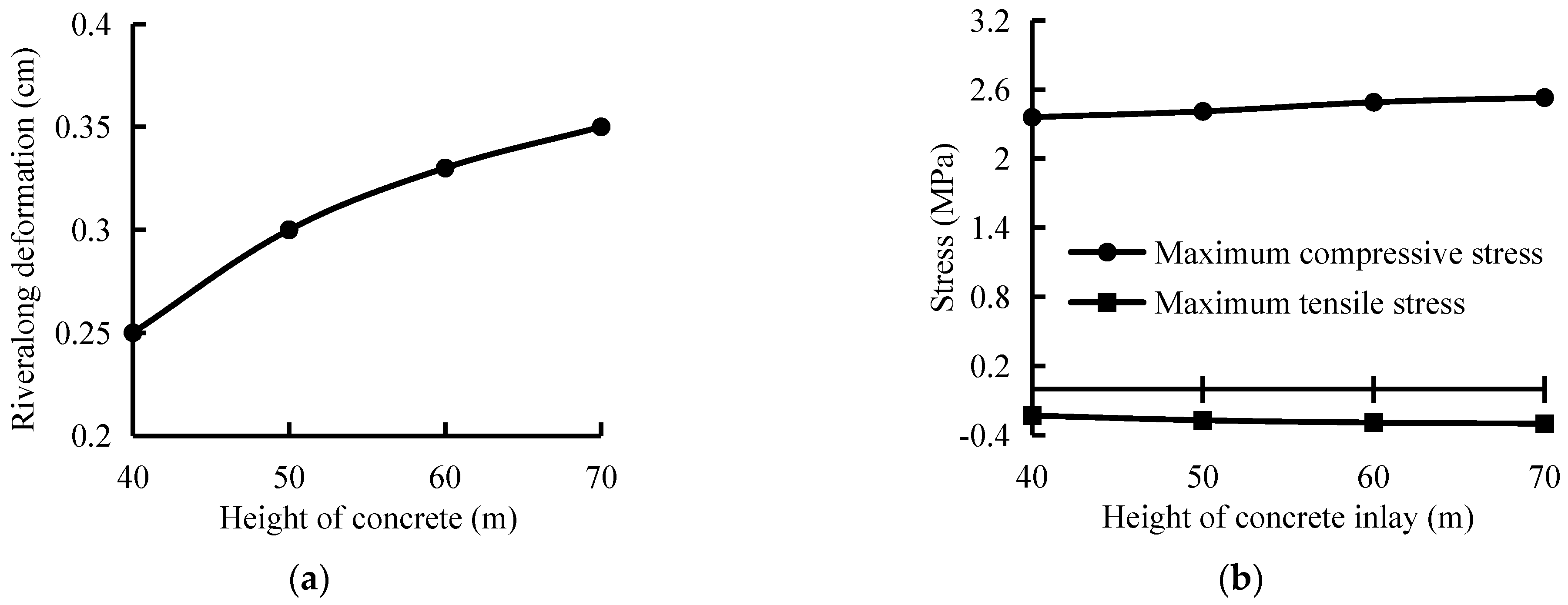
3.3. Sensitivity Analysis of the Embedded Concrete Body Height
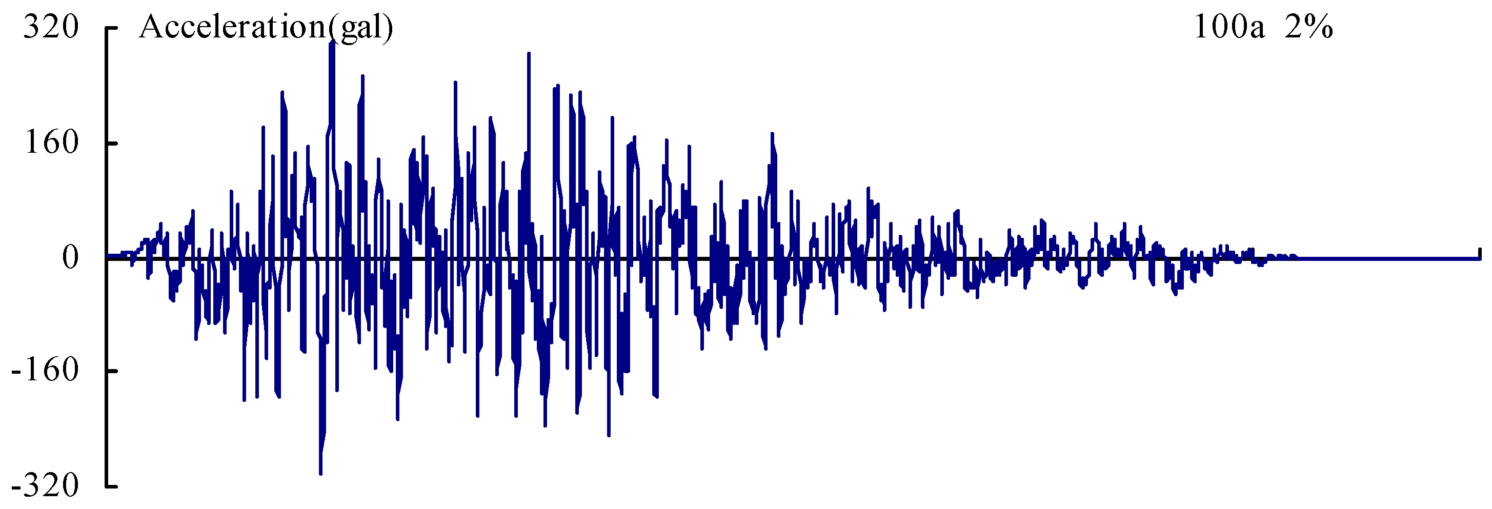
4. Dynamic Deformation Analyses
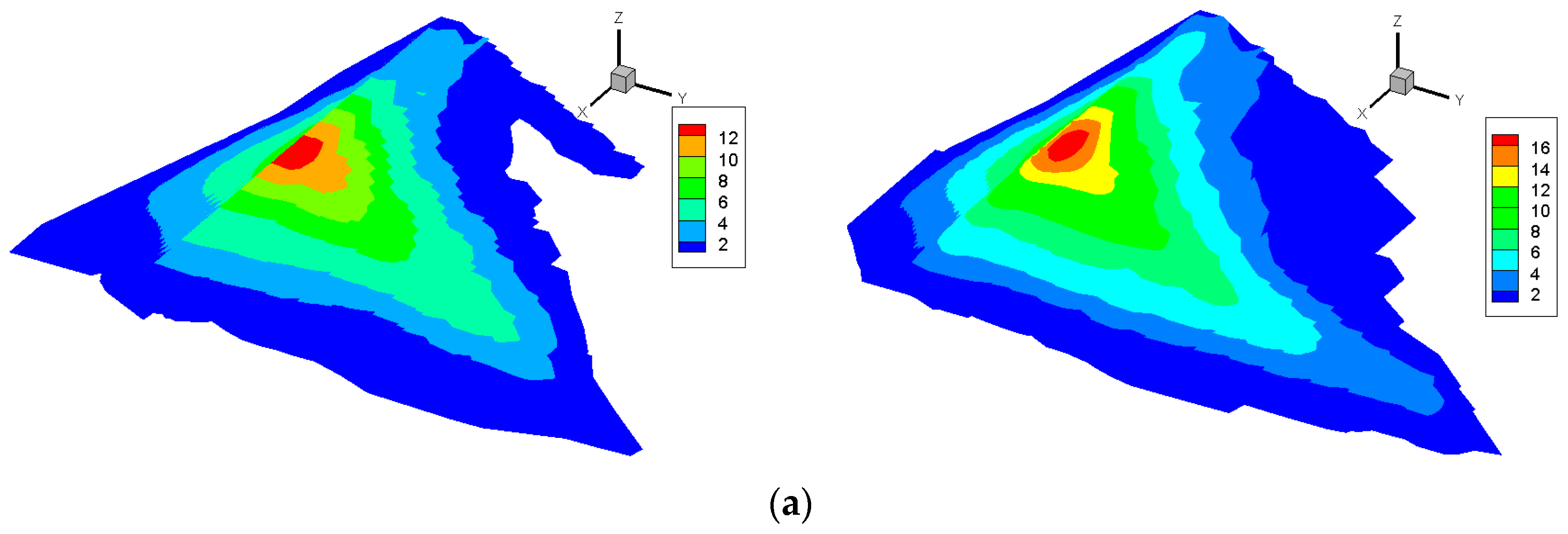
4.1. Rockfill Dynamic Deformation Analysis
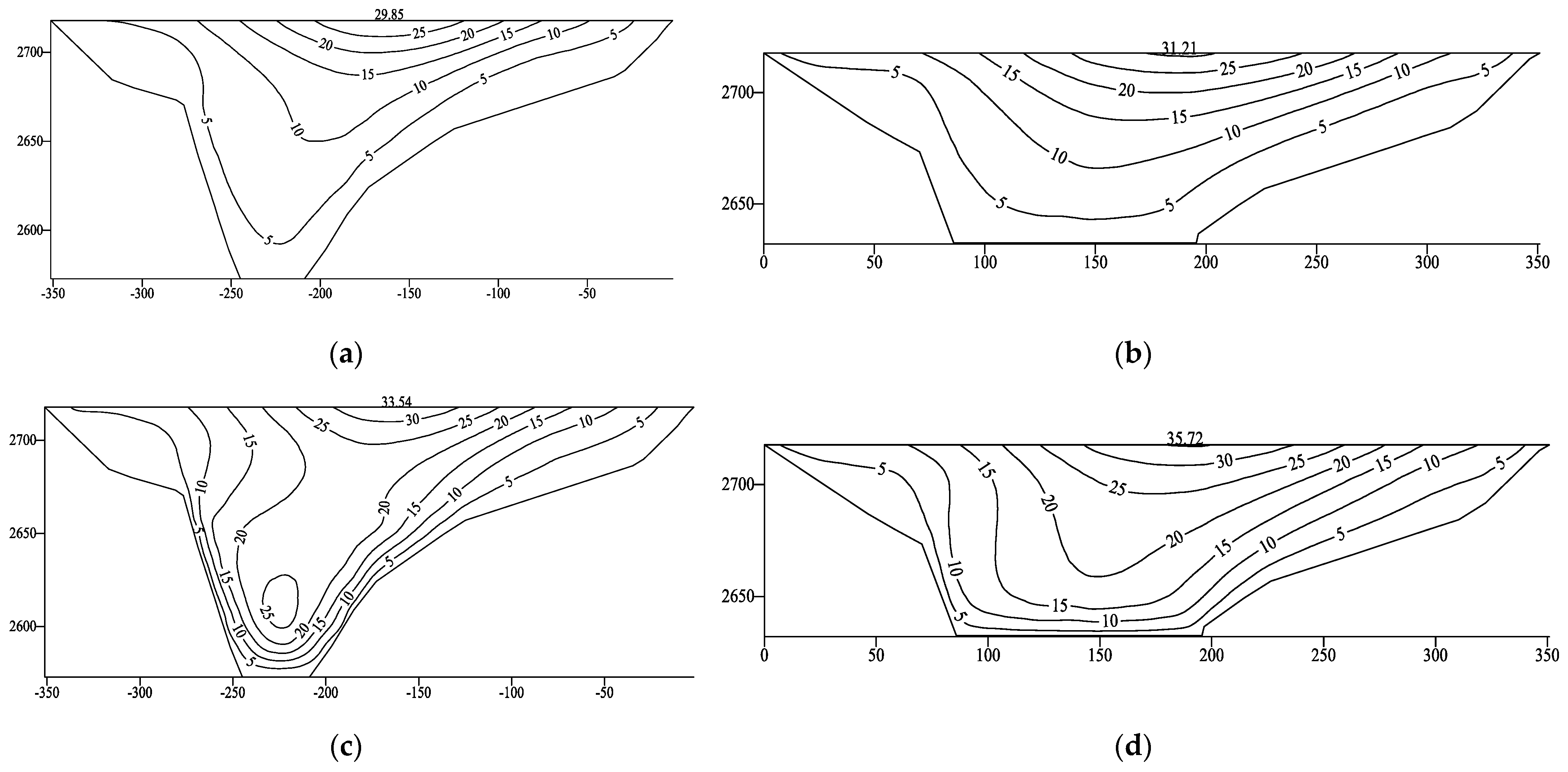
4.2. Dynamic and Static–Dynamic Deformation Analyses of the Concrete-Face Slab
5. Conclusions
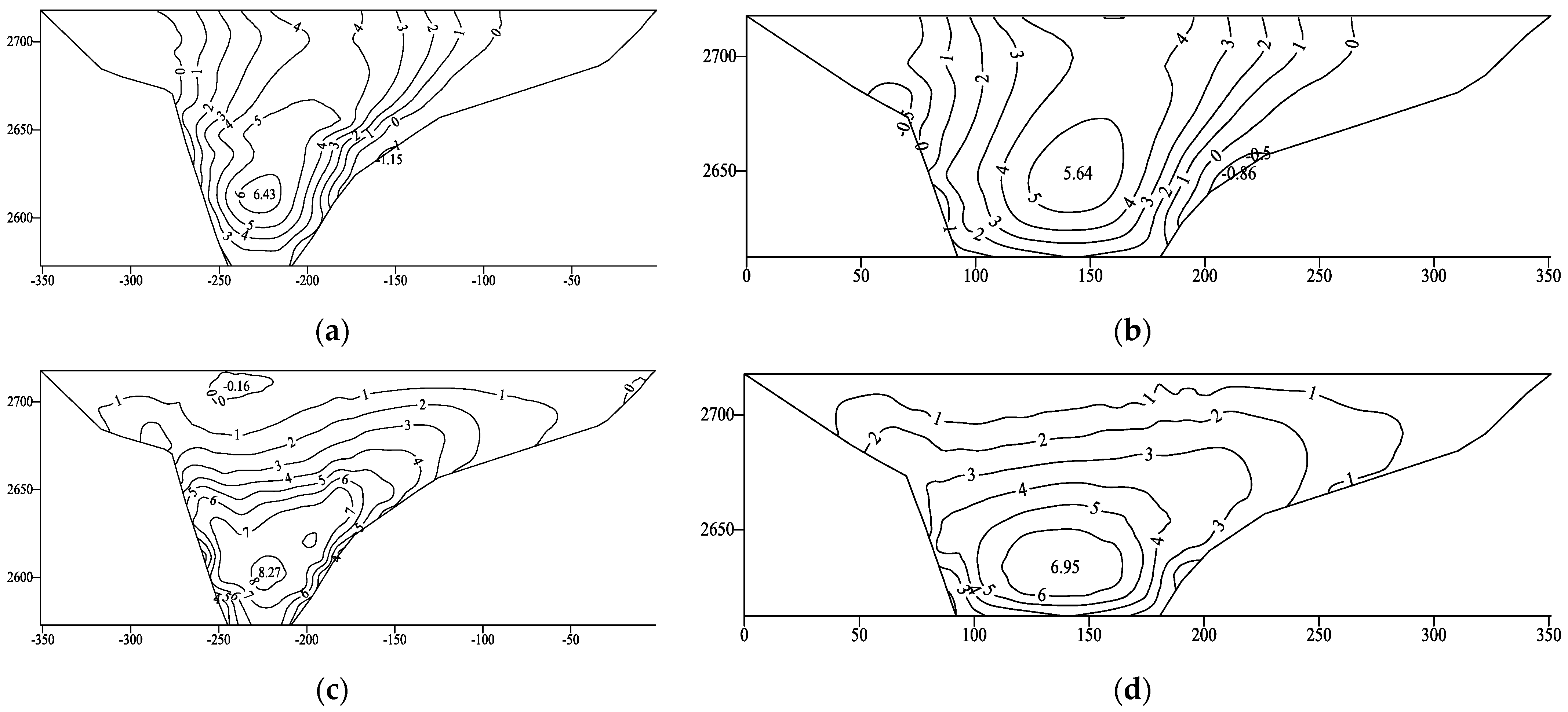
- Compared with a CCFRD, an embedded concrete body under a static load inhibited the static displacement of the rockfill along the river. When the height of the embedded concrete body was 40 m, the maximum horizontal displacements of the upstream and downstream rockfill were 2.1 and 0.6 cm less than those of the CCFRD, respectively. Moreover, owing to the stress on the embedded concrete body, the tensile stress along the slope of the concrete-face slab was completely eliminated, the axial stress was greatly reduced, the maximum deflection of the concrete-face slab decreased by 5.21 cm, and the area experiencing maximum stress shifted to 0.47 times the dam height.
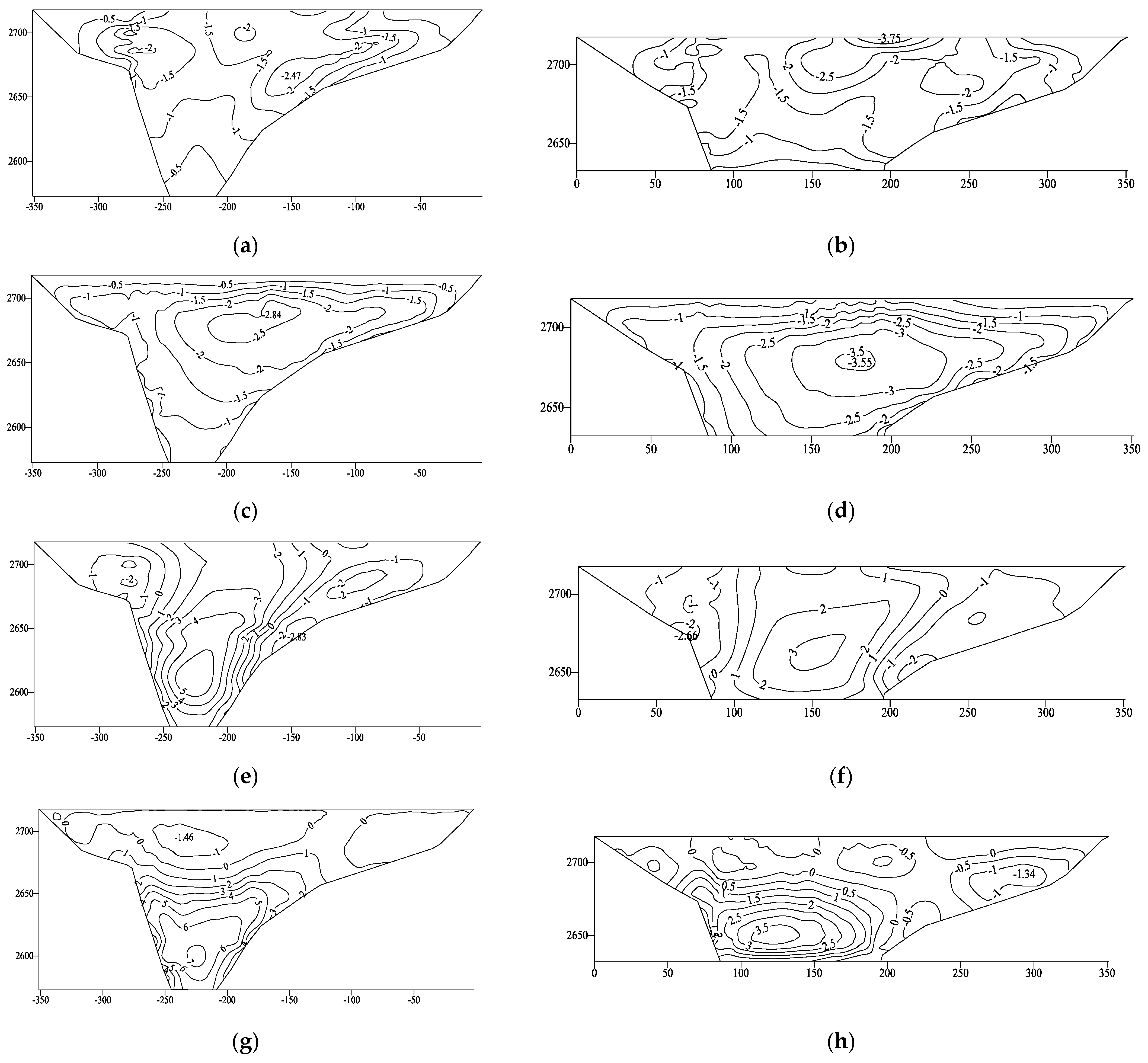
- Under the actions of dynamic and static–dynamic superposition, the deformation of the rockfill and concrete-face slab increased slightly, whereas the tensile stress on the concrete-face slab decreased slightly after setting the concrete-face slab. The permanent seismic subsidence of the rockfill body accounted for approximately 0.2% of the maximum dam height, the ratio of the maximum dynamic value to the maximum static value of the concrete-face slab increased from 1.7 to 2.9, and the cumulative static and dynamic value of the deflection of the concrete-face slab reached 35.72 m. Overall, the dynamic results for the ECFRD were within the controllable range of a 150 m concrete-face rockfill dam.
- The ECFRD at the hydropower station was technically feasible and could effectively improve the static stress–strain characteristics of the dam body while shortening the length of the concrete-face slab and the joint. Under earthquake conditions, local reinforcement and other reinforcement measures could be applied to adapt the ECFRD to a 200–300 m high dam. For related projects, considering the project cost and stability of the embedded concrete body, we recommend that the height of the embedded concrete body should be 60 m, which is 0.4 times the height of the dam in this study.
Author Contributions
Funding
Data Availability Statement
Acknowledgments
Conflicts of Interest
References
- Li, J.; Lu, X.; Chen, J.; Yang, S.; Kuang, C.; Fan, Y.; Hu, K. Reliability-monitoring data coupled model for concrete slab safety evaluation of CFRD and its engineering application. Structures 2022, 35, 520–530. [Google Scholar] [CrossRef]
- Khalid, M.I.; Park, D.; Fei, J.; Nguyen, V.; Nguyen, D.; Chen, X. Selection of efficient earthquake intensity measures for evaluating seismic fragility of concrete face rockfill dam. Comput. Geotech. 2023, 163, 105721. [Google Scholar] [CrossRef]
- Xu, J.; Xu, H.; Yan, D.; Chen, K.; Zou, D. A Novel Calculation Method of Hydrodynamic Pressure Based on Polyhedron SBFEM and Its Application in Nonlinear Cross-Scale CFRD-Reservoir Systems. Water 2022, 14, 867. [Google Scholar] [CrossRef]
- Dakoulas, P. Longitudinal vibrations of tall concrete faced rockfill dams in narrow canyons. Soil Dyn. Earthq. Eng. 2012, 41, 44–58. [Google Scholar] [CrossRef]
- Zhao, W.; Wang, Z.; Zhang, H.; Wang, T. A Model Predicting the Maximum Face Slab Deflection of Concrete-Face Rockfill Dams: Combining Improved Support Vector Machine and Threshold Regression. Water 2023, 15, 3474. [Google Scholar] [CrossRef]
- Shakarami, L.; Javdanian, H.; Zarif Sanayei, H.R.; Shams, G. Numerical investigation of seismically induced crest settlement of earth dams. Model. Earth Syst. Environ. 2019, 5, 1231–1238. [Google Scholar] [CrossRef]
- Shao, L.; Wang, T.; Wang, Y.; Wang, Z.; Min, K. A Prediction Model and Factor Importance Analysis of Multiple Measuring Points for Concrete Face Rockfill Dam during the Operation Period. Water 2023, 15, 1081. [Google Scholar] [CrossRef]
- Arici, Y. Evaluation of the performance of the face slab of a CFRD during earthquake excitation. Soil Dyn. Earthq. Eng. 2013, 55, 71–82. [Google Scholar] [CrossRef]
- Nusier, O.K.; Alawneh, A.S. Kafrein Earth dam probabilistic seismic hazard assessment. Soil Mech. Found. Eng. 2006, 43, 211–215. [Google Scholar] [CrossRef]
- Aman, S.; Rezk, M.A.; Nasr, R. Effect of Berm Properties on Non-Cohesive Earth Dam Failure due to Overtopping. KSCE J. Civ. Eng. 2023, 27, 1974–1984. [Google Scholar] [CrossRef]
- Kim, Y.S.; Seo, M.W.; Lee, C.W.; Kang, G.C. Deformation characteristics during construction and after impoundment of the CFRD-type Daegok Dam, Korea. Eng. Geol. 2014, 178, 1–14. [Google Scholar] [CrossRef]
- Liu, Y.; Zheng, D.; Cao, E.; Wu, X.; Chen, Z. Cracking risk analysis of face slabs in concrete face rockfill dams during the operation period. Structures 2022, 40, 621–632. [Google Scholar] [CrossRef]
- Yao, F.H.; Guan, S.H.; Yang, H.; Chen, Y.; Qiu, H.F.; Ma, G.; Liu, Q.W. Long-term deformation analysis of Shuibuya concrete face rockfill dam based on response surface method and improved genetic algorithm. Water Sci. Eng. 2019, 12, 196–204. [Google Scholar] [CrossRef]
- Xu, B.; Zou, D.; Kong, X.; Hu, Z.; Zhou, Y. Dynamic damage evaluation on the slabs of the concrete faced rockfill dam with the plastic-damage model. Comput. Geotech. 2015, 65, 258–265. [Google Scholar] [CrossRef]
- Kartal, M.E.; Bayraktar, A.; Basaga, H.B. Nonlinear finite element reliability analysis of Concrete-Faced Rockfill (CFR) dams under static effects. Appl. Math. Model. 2012, 36, 5229–5248. [Google Scholar] [CrossRef]
- Wen, L.; Chai, J.; Xu, Z.; Qin, Y.; Li, Y. Monitoring and numerical analysis of behaviour of Miaojiaba concrete-face rockfill dam built on river gravel foundation in China. Comput. Geotech. 2017, 85, 230–248. [Google Scholar] [CrossRef]
- Mata, J.; Gomes, J.P.; Pereira, S.; Magalhaes, F.; Cunha, A. Analysis and interpretation of observed dynamic behaviour of a large concrete dam aided by soft computing and machine learning techniques. Eng. Struct. 2023, 296, 116940. [Google Scholar] [CrossRef]
- Ghaemi, A.; Konrad, J.M. Empirical approaches to estimate the nonlinear dynamic responses of earth-core rockfill dams subjected to earthquake ground motions. Soils Found. 2022, 62, 101106. [Google Scholar] [CrossRef]
- Wang, Y.; Wu, Z.; Qu, F.; Zhang, W. Numerical investigation on crack propagation process of concrete gravity dams under static and dynamic loads with in-crack reservoir pressure. Theor. Appl. Fract. Mec. 2022, 62, 101106. [Google Scholar] [CrossRef]


| Dam Material | Density (g/cm3) | Angle of Internal Friction (°) | Elastic Modulus | Initial Stiffness Index | Damage Ratio | Volume Compression Modulus Coefficient | Volume Deformation Modulus Coefficient | Unloading-Repeated Addition Coefficient |
|---|---|---|---|---|---|---|---|---|
| 2A | 2.25 | 54.8 | 1023.3 | 0.32 | 0.61 | 500.0 | 0.25 | 2046.6 |
| 3A | 2.17 | 56.2 | 1438.6 | 0.23 | 0.72 | 791.5 | 0.02 | 2877.2 |
| 3B | 2.15 | 56.6 | 1412.5 | 0.22 | 0.72 | 772.2 | 0.04 | 2825.0 |
| 3C | 2.15 | 52.2 | 800.0 | 0.26 | 0.62 | 400.0 | 0.29 | 1600.0 |
| Material | Density (g/cm3) | Elastic Modulus (GPa) | Poisson Ratio |
|---|---|---|---|
| CS | 2.4 | 28 | 0.167 |
| 2B | 2.4 | 30 | 0.167 |
| Foundation | 2.7 | 11.9 | 0.167 |
| Dam Type | Settlement (cm) | Upstream Deformation (cm) | Downstream Deformation (cm) |
|---|---|---|---|
| CCFRD | 46.2 | 5.0 | 7.4 |
| ECFRD | 45.6 | 2.9 | 6.8 |
| Dam Type | Axial Compressive Stress (MPa) | Axial Tensile Stress (MPa) | Compressive Stress along the Slope (MPa) | Tensile Stress along the Slope (MPa) | Deflection (cm) |
|---|---|---|---|---|---|
| CCFRD | 6.34 | 1.15 | 8.27 | 0.16 | 19.46 |
| ECFRD | 5.64 | 0.86 | 6.95 | / | 6.8 |
| Dam Type | Displacement along the River | Vertical Deformation | Permanent Deformation along the River | Permanent Vertical Deformation |
|---|---|---|---|---|
| CCFRD | 13.1 | 6.3 | 19.9 | 27.7 |
| ECFRD | 17.1 | 7.5 | 21.6 | 31.3 |
| Deformation and Strain | CCFRD | ECFRD | Deformation and Strain | CCFRD | ECFRD |
|---|---|---|---|---|---|
| Deflection | 29.85 | 31.21 | Maximum axial dynamic tensile stress | 2.47 | 3.75 |
| Total deflection | 33.54 | 35.72 | Maximum dynamic tensile stress superposition in the slope direction | 2.83 | 2.66 |
| Maximum dynamic tensile stress in the slope direction | 2.84 | 3.55 | Maximum axial dynamic tensile stress superposition | 1.46 | 1.34 |
Disclaimer/Publisher’s Note: The statements, opinions and data contained in all publications are solely those of the individual author(s) and contributor(s) and not of MDPI and/or the editor(s). MDPI and/or the editor(s) disclaim responsibility for any injury to people or property resulting from any ideas, methods, instructions or products referred to in the content. |
© 2023 by the authors. Licensee MDPI, Basel, Switzerland. This article is an open access article distributed under the terms and conditions of the Creative Commons Attribution (CC BY) license (https://creativecommons.org/licenses/by/4.0/).
Share and Cite
Qu, P.; Chai, J.; Xu, Z. Three-Dimensional Static and Dynamic Analyses of an Embedded Concrete-Face Rockfill Dam. Water 2023, 15, 4189. https://doi.org/10.3390/w15234189
Qu P, Chai J, Xu Z. Three-Dimensional Static and Dynamic Analyses of an Embedded Concrete-Face Rockfill Dam. Water. 2023; 15(23):4189. https://doi.org/10.3390/w15234189
Chicago/Turabian StyleQu, Pengfei, Junrui Chai, and Zengguang Xu. 2023. "Three-Dimensional Static and Dynamic Analyses of an Embedded Concrete-Face Rockfill Dam" Water 15, no. 23: 4189. https://doi.org/10.3390/w15234189
APA StyleQu, P., Chai, J., & Xu, Z. (2023). Three-Dimensional Static and Dynamic Analyses of an Embedded Concrete-Face Rockfill Dam. Water, 15(23), 4189. https://doi.org/10.3390/w15234189