Article

Seepage Model of Heterogeneous Municipal Solid Waste Landfill and Application under Process of Waste Accumulation

1
College of Architecture and Civil Engineering, Xi’an University of Science and Technology, Xi’an 710054, China
2
China Gezhouba Group No. 3 Engineering Co., Ltd., Xi’an 710077, China
*
Author to whom correspondence should be addressed.
Water 2023, 15(23), 4115; https://doi.org/10.3390/w15234115
Submission received: 27 October 2023 / Revised: 22 November 2023 / Accepted: 24 November 2023 / Published: 28 November 2023
(This article belongs to the Section Soil and Water)

Abstract

:
The distribution of leachate directly impacts the safety and stability of the landfill, so it is important to research the distribution of seepage characteristics and migration patterns of leachate. The study aims to investigate the impact of heterogeneous permeability distribution and clogging of the drainage layer on leachate transportation in landfills. To achieve this, a heterogeneous transient seepage model was developed. Results showed that when considering the heterogeneous permeability of the waste in the buried depth direction, the maximum perched water level was higher, which is not conducive to the safety and stability of the landfill. Taking Xi’an Jiangcungou Landfill as a research object, the maximum perched water level of each waste layer was higher compared to the homogeneous condition when considering the landfill process and heterogeneous permeability. The differential value ranged from 0.08 m to 1.88 m. Furthermore, the calculation results obtained from the heterogeneous seepage model were found to be in good agreement with both actual field data and referenced survey data, thus confirming the reliability of the model. These research findings not only offer technical support but also provide a solid theoretical foundation for leachate level control and safety and stability assessments.

1. Introduction

As one of the important methods to deal with municipal solid waste (MSW) in many countries, landfills have garnered significant attention from scholars across various disciplines due to their importance in ensuring safety and stability. After analyzing numerous landfill accidents both domestically and internationally, it has been determined that leachate distribution plays a crucial role in landfill instability [1,2,3,4,5]. Meanwhile, there are a lot of pollutants and heavy metal ions in the leachate which have some influence on the surrounding soil and groundwater [6,7]. However, waste permeability plays a crucial role in predicting leachate migration [8]. In addition, significant heterogeneity and a wide range of waste permeability are observed at different buried depths in landfills due to the complex composition of waste and the employed landfill method [9]. Thus, in the seepage numerical simulation of landfill, setting a reasonable permeability distribution is a topic worth studying.
Landfill leachate levels generally include three forms: the main water level, the perched water level, and the drainage layer level. In the landfill disposal process, a layer of loess (approximately 0.3 m thick) is placed on top of the waste layer. This “middle covering layer” serves to minimize rainfall infiltration, control mosquitoes breeding, and mitigate air pollution. When filling waste in the upper part of the middle covering layer, the leachate flows down under the influence of the water head pressure. When the amount of rainfall infiltration exceeds the osmotic capacity of the middle covering layer, a significant accumulation of leachate occurs in the middle layer, resulting in the formation of localized perched water [10]. Furthermore, when the permeability of the middle covering layer increases and the drainage layer fails, the perched water level transitions into the main water level. Based on domestic and international studies [5,11], it has been observed that the drainage systems of most landfills become clogged under rainfall infiltration, leading to the accumulation of leachate at the bottom of landfill. This accumulation results in high water levels and large pore pressure, posing a significant threat to landfill safety. In landfills, Darcy’s seepage and priority seepage coexist, with the larger pores gradually decreasing as waste compaction increases, making Darcy’s seepage the primary form of seepage flow in landfills [12,13].
The research into landfill leachate level includes field tests and numerical analysis methods. The common methods of water level measurement in landfill include the water level gauge method [14], pore pressure meter method [15], electrical resistivity tomography [16,17], partitioning gas tracer test [18], neutron probes [19], and fiberoptic sensors, etc. [20]. Grellier et al. [21] set a large number of electrodes on the surface of landfill under injecting leachate in a landfill of France. The main engine emitted electrical currents through the electrodes to the bottom of the landfills, thereby facilitating the acquisition of resistivity distribution and leachate levels. To account for the distinctive characteristics, He [14] proposed an enhanced method for in situ exploration of water levels across multiple layers. This method involved building upon the conventional approach of monitoring water levels across multiple layers, specifically focusing on accurately measuring the location and distribution of leachate levels within the middle covering layer. Additionally, the process of water level recovery was simulated using finite element software, and the saturated permeability of waste was calculated using an inverse method. Zhang et al. [15] monitored the pore pressure in different landfill locations using a differential resistance osmometer and determined the middle covering layer location and leachate level.
In terms of numerical analysis, the seepage of landfill is considered as saturated-unsaturated seepage [22,23,24,25,26,27,28,29,30,31,32]. Considering the heterogeneous characteristic of waste, Wang et al. [33] analyzed the transport process of leachate of landfill by developing a saturated-unsaturated mathematical model. Zhang et al. [22] established two-dimensional (2-D) saturated-unsaturated seepage control equations for landfill units, calculated the seepage field within the landfill, and investigated the patterns of leachate accumulation in the drainage layer. Then, they measured the saturated permeability and soil-water characteristic curve (SWCC) of waste, derived the permeability function, and calculated the slope stability of landfill under the conditions of an effective or failed flood interception ditch [23]. Considering the landfill process, Zhang et al. [13,23] researched the formation process of perched water levels in waste units. They calculated the leachate distribution in Qizishan Landfill and verified the results through on-site monitoring of water level. To measure the permeability, Zhang [34] examined the changes in saturated permeability with respect to burial depth and utilized this data to calculate landfill seepage and leachate production, which showed good agreement with test results. Subsequently, Yang et al. [26] conducted further research in this area. Jang et al. [35] obtained the saturated permeability of waste through laboratory testing and investigated the changes in leachate levels based on compaction degree and overburden thickness. By means of a series of tests and the aforementioned numerical simulations, an in-depth analysis was conducted to investigate the seepage failure and overall stability of the landfill. This research facilitated the accurate prediction of leachate levels and the formulation of effective measures aimed at enhancing the stability of the landfill [36,37].
A large number of studies have been carried out on the layered simplification of the waste permeability characteristics [8,12,14,22,23,26]. However, these studies did not completely show the variations in landfill seepage characteristics in relation to burial depth, and did not account for the actual vertical heterogeneity in landfill permeability. To accurately reflect the seepage law and leachate migration process in landfills, this study established a heterogeneous and saturated-unsaturated seepage model and analyzed the influence of seepage characteristic distribution and clogging of the drainage layer on the landfill seepage field.

2. Seepage Mechanism of Municipal Solid Waste Landfill
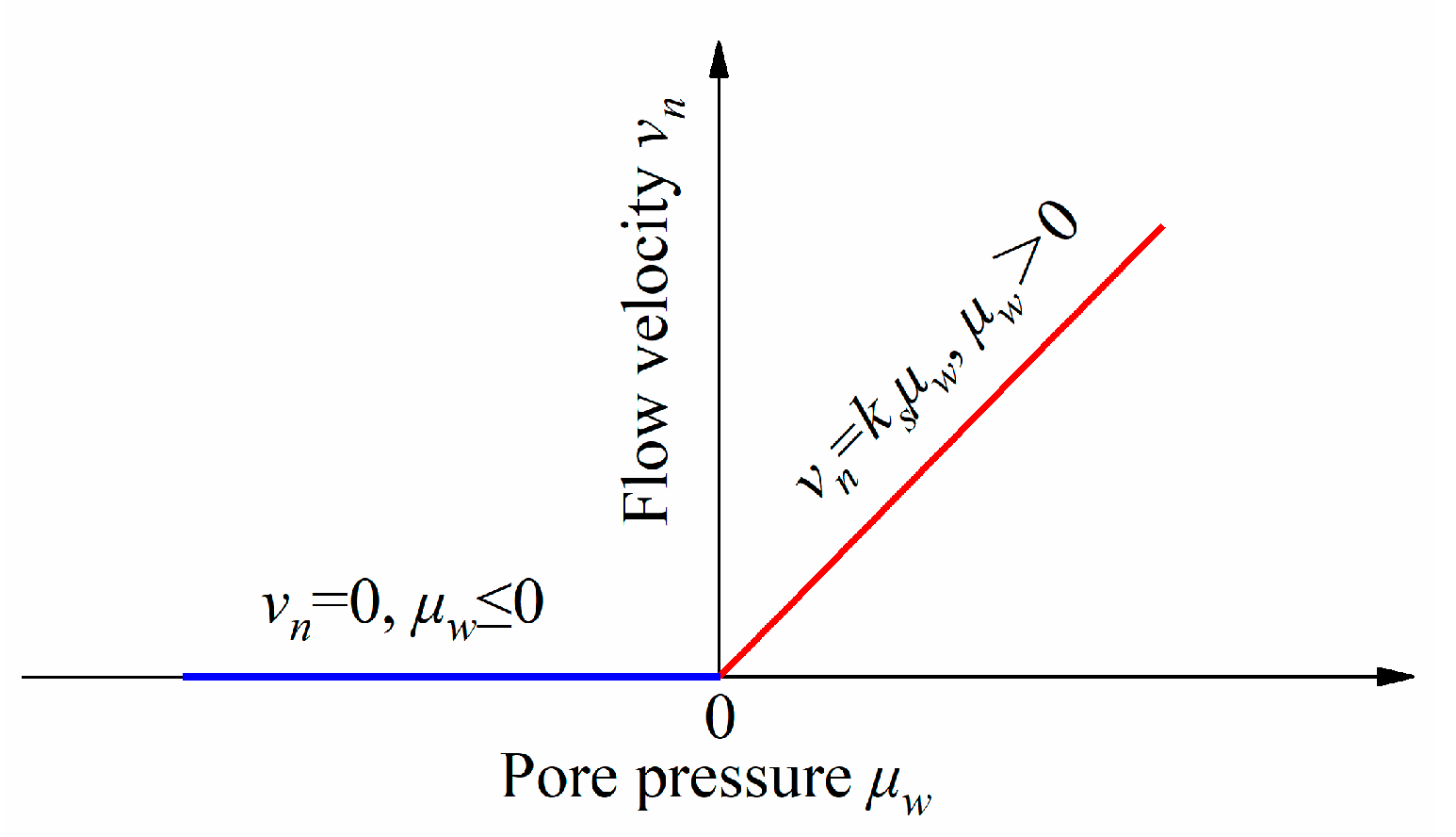
2.1. Seepage Theory

Within the waste unit, the study of unsaturated seepage mainly focuses on the movement of liquids and gases through the waste material. In the process of waste changing from unsaturated to saturated, it is assumed that the gas does not flow and that the movable liquid fills the pore. As such, the pore volume decreases and the moisture content increases gradually, until reaching a saturation of 1.0.
The waste used as filling material in landfills exhibits complex components and characteristics, leading to significant heterogeneity in landfill composition. Darcy seepage is the primary form of seepage in landfills, and, typically, preferential flow resulting from seepage channels formed by large pores can be disregarded. Therefore, saturated-unsaturated seepage in landfill can be viewed as a Darcy seepage condition [13].
According to a seepage experiment with sand, Darcy proposed that water seepage velocity is proportional to the hydraulic gradient. The law was applied in saturated seepage at first, but it can also be employed for unsaturated seepage [38,39]. The main distinction between saturated seepage and unsaturated seepage in waste is that the permeability of saturated material remains constant, while the permeability of unsaturated material is dependent on certain factors, such as saturation, water content, or matric suction. The expression of Darcy’s law [40,41] is as follows:
q = k J
Or,
v = k J = k h l
where q is the water flux per unit volume, k is the permeability of waste, J is the hydraulic gradient, v is the seepage velocity or Darcy velocity in waste, h is the hydraulic head, and l is the seepage path.
According to the principle of mass conservation, the difference in quality between the inflow and outflow water of a waste unit is equal to the change rate in water quality over time. Taking into account the relationship of water storage, waste porosity, and density, the three-dimensional (3D) unsteady seepage continuity equation is derived from the relations above [42,43]:
v x x + v y y + v z z = - S a h t
where S a is the water storage per unit volume, and, when the head drops a unit, the stored water is released due to waste compression and water expansion in the saturated waste per unit volume.
For steady seepage, it is assumed that water and waste are incompressible, that the porosity of the waste remains constant in the seepage process, and the change rate of water quality in the waste is zero at any time. The 3-D steady seepage flow continuity equation is as follows:
v x x + v y y + v z z = 0
The two-dimensional (2-D) steady seepage flow continuity equation is as follows:
v x x + v y y = 0
When considering the compressibility of waste and water, the 3-D unsteady seepage flow differential equation is obtained by combining Equations (2) and (3), as follows [40]:
x k x h x + y k y h y + z k z h z = S a h t
where k x , k y , and k z are the permeabilities of the waste units along the x , y and z directions, respectively.
The 3-D steady seepage flow differential equation can be formulated without considering the compressibility of waste and water, as follows:
x k x h x + y k y h y + z k z h z = 0
The 2-D steady seepage flow differential equation is as follows:
x k x h x + y k y h y = 0

2.2. Heterogeneous Seepage Theory

When the permeability varies at different locations or when the waste is composed of a variety of materials, the whole seepage field is characterized by heterogeneity. Due to differences in pore distribution, compaction degree, and particle composition, MSW exhibits varying degrees of heterogeneity. Heterogeneity is particularly significant in projects involving rolled compact concrete (RCC) dams and MSW landfills. In these cases, the permeability of the material is influenced by compaction and varies with depth, with a decrease in permeability observed as depth increases.
As shown in Figure 1, the issue of unstable seepage flow in heterogeneous waste can be transformed into single homogeneous waste seepage problems. Seepage of multi-layer waste is divided into horizontal (along the x direction) and vertical (along the z direction) seepage conditions. Supposing that each layer of waste is isotropic, the permeabilities are k1, k2, …, kn, and the corresponding waste thicknesses are t1, t2, …, tn, respectively.
During the landfill stabilization process, waste undergoes degradation and settlement, leading to significant changes in permeability along the vertical direction. Therefore, this research aims to thoroughly investigate the heterogeneous permeability properties of waste in the vertical direction.
Considering the vertical seepage of heterogeneous waste, the total hydraulic gradient of multi-layer waste is J and the hydraulic gradients of each layer are J1, J2, …, Jn, respectively. The total seepage quantity in the vertical direction is equal to the seepage quantity of each layer [40], that is:
Q z = q 1 z = q 2 z = q 3 z = = q n z
where Q z is the total seepage flow in heterogeneous waste along the z direction and q n z is the permeability along the z direction in the first layer of waste.
Based on Darcy’s law, the above equation can be converted into the following:
k z J = k 1 z J 1 = k 2 z J 2 = k 3 z J 3 = = k n z J n
where k z is the equivalent permeability of heterogeneous waste along the z direction, and k n z is the permeability along the z direction in the n layer of waste.
Considering that the total head loss of waste is the sum of each layer’s waste head loss, Equation (11) is established.
J t = J 1 t 1 + J 2 t 2 + J 3 t 3 + + J n t n
Equation (12) is obtained from the simultaneous equations of Equations (10) and (11), as follows:
k z = t t 1 k 1 z + t 2 k 2 z + t 3 k 3 z + + t n k n z
From the equation above, it is evident that the vertical equivalent permeability of multi-layer waste with equal thickness is primarily influenced by the layer and the minimum permeability of single-layer waste. The more layers there are, the greater the relative vertical equivalent permeability. Considerable errors are produced when the waste thickness is greater or when there is a substantial difference in permeability between each layer. To minimize the error, it is recommended to consider smaller thicknesses for each layer of waste during computation, as this approach closely reflects the actual seepage situation.
By defining the free seepage boundary, the drainage boundary at the bottom of the model was set, and the principle is shown in Figure 2. In seepage calculations, the flow velocity of fluid is proportional to the pore pressure when pore pressure exists at the boundary. Conversely, the flow velocity value of fluid is 0 when the negative pore pressure exists at the boundary. The pore pressure is approximately equal to zero when the slope value is bigger. The relationship between the seepage coefficient and the permeability of drainage material is as follows [44]:
k s = 10 5 k d / γ w c
where k s is the seepage coefficient, k d is the permeability of the drainage material, γ w is the bulk density of water, and c is the typical length of the unit.

3. Materials and Models

The leachate level significantly affects landfill stability, and is primarily influenced by factors, such as rainfall, wastewater content, degradation, surface water, and groundwater. Landfills are typically constructed above the groundwater level, with drainage systems installed at the bottom and in the surrounding areas. Consequently, groundwater has little impact on the leachate. However, due to factors, such as the height of the landfill, its large capacity, high initial water content, clogging of the drainage system, and rainfall, the transport behavior of leachate and the stability of the landfill become particularly important.
Due to the degradation of municipal solid waste (MSW) and the pressure from above, the void ratio of the landfill decreases gradually. This leads to the gradual clogging of the drainage system and the rapid accumulation of leachate, resulting in an increase in the leachate level and instability and failure of slope. This study aims to analyze the influence of heterogeneous permeability characteristics on the leachate water level through the establishment of waste units. The Xi’an Jiangcungou Landfill was selected as the research object for analyzing the impact of heterogenous waste permeability on the seepage field of the landfill.

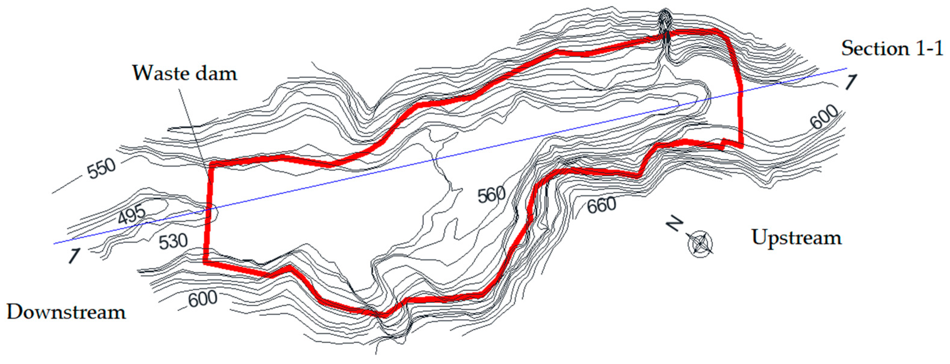
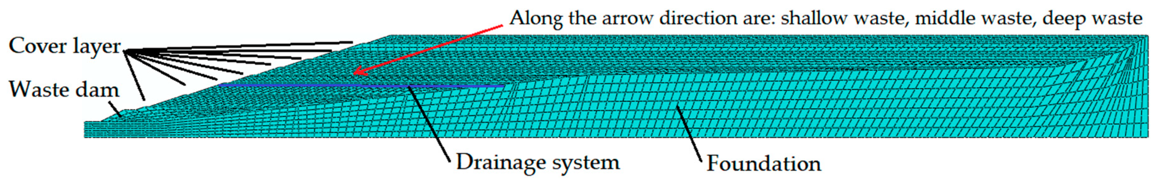
3.1. Profile of Xi’an Jiangcungou Landfill

The landfill is located in Xi’an and is a typical valley landfill. The main sources of waste include kitchen waste, road cleaning waste, and commercial waste. Since its establishment in June 1994, the daily waste processing capacity of the facility has increased significantly, from 1260 tons in 1994 to 10,000 tons in 2017. The landfill spans approximately 733,700 m2 and has a design height of 130 m. A refuse dam is present downstream at an elevation of 509 m, serving to prevent waste sliding and to establish the initial capacity of the landfill. Additionally, a retaining dam is employed upstream to prevent waste sliding and the inflow of floodwater.
During the landfill construction process, several issues were encountered. For example, in 2000, there was cracking of the retaining dam, leading to the reinforcement of the slope with dry masonry in 2001. However, leachate continued to seep from the slope protection and waste slope downstream. High leachate levels and uneven settlement of waste were identified as the main factors contributing to leachate leakage and dam cracking. In 2007, excessive pore pressure during continuous rainfall caused downstream slope instability, prompting modification of the slope ratio from ½ to 1/3 and the implementation of reinforcement measures. In 2011, after a flood, landslides occurred in the fifth and sixth layers of the landfill due to delayed leachate discharge, resulting in the involvement of approximately 20,000 m3 of waste. In April 2016, a local landslide occurred on the upstream slope at elevations of 580 m to 600 m. The following year, due to continuous rainfall, the leachate level increased and overflowed. Therefore, conducting seepage field research in the landfill is crucial to ensure its safety and operation. During on-site excavations in certain areas of the downstream slope, it was observed that leachate overflowed to a depth of approximately 0.5 m on the surface, and the waste pit was filled within minutes. The leachate level at this location was found to be very high. Conversely, leachate significantly decreased during winter. There are numerous pollutants in the soil surrounding the landfill, which can be determined by measuring the chemical oxygen demand (COD), biochemical oxygen demand (BOD5), and heavy metal ions [6,7].

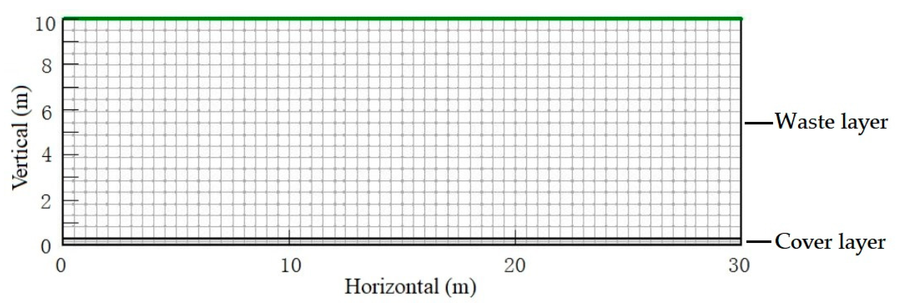
3.2. Parameters and Scheme Design of Waste Unit

In the seepage analysis of waste units, the analysis considered rainfall and wastewater content. An annual rainfall of 1000 mm was assumed to investigate the impact on leachate levels in relation to the permeabilities of the cover layer and the waste. A rainfall of 1000 mm was selected to accurately depict the impact of heterogeneous permeability coefficient on leachate distribution. Choosing a smaller amount of rainfall would result in lower leachate levels in several cases, which would not effectively demonstrate the significance of the heterogeneous permeability. The load was simulated by unit flow on the surface of the landfill. The leachate flowed from up to down due to the force of gravity, and it flowed into the lower waste unit through the cover layer. When researching the seepage rules of the waste unit, the calculation parameters included rainfall intensity (q), which was 3.17 × 10⁻⁸ m/s, while the three kinds of permeabilities concerning the cover layer were 5.0 × 10⁻⁸ m/s, 1.0 × 10⁻⁸ m/s, and 5.0 × 10⁻⁹ m/s (Kc1, Kc2 and Kc3).
The MSW’s saturated permeability in landfill exhibited significant heterogeneity in the vertical direction due to the waste degradation and compression settlement. Statistical analysis revealed a wide range of saturated permeability values within the same landfill [30,45,46,47]. Therefore, it is necessary to subdivide the landfill units during the calculation process. Taking the shallow waste unit for example, the saturated permeabilities of Xi’an Jiangcungou Landfill differed by one order of magnitude within 10 m depth [9], and the permeability curves of landfill were shown in Figure 3. Finally, the formation patterns of perched water levels were analyzed under varying heterogeneity conditions by controlling the layer of the waste unit (n).
Referring to the specification, it was determined that the initial volume water content of waste was 50% according to the soil-water characteristic curves [48] and physical components of actual landfill [46,48]. The corresponding initial pore water pressure (−2 kPa) in the abovementioned curves was regarded as the initial condition, and the soil-water characteristic curve of loess was applied for the unsaturated parameter of the cover layer [49].
In unsaturated media, the relationship between permeability and matric suction is as follows:
k w = a 1 k w s a t / a 1 + b 1 × u a u w c 1
k w s = k w s a t / k w
where k w is the permeability, k w s a t is the saturated permeability, k w s is the permeability reduction factor, u a is the gas pressure inside the material, u w is the water pressure inside the material, and a 1 , b 1 and c 1 are the coefficients of the material.
The relationship between the saturation and matric suction can be expressed as follows:
S r = S i + S n S i a 2 / a 2 + b 2 × u a u w c 2
where S r is the saturation, S i is the residual saturation, S n is the maximum saturation, and a 2 , b 2 and c 2 are the coefficients of the material.
In the unsaturated seepage calculation, the default k w s is equal to 1.0 when S r is greater or equal to 1.0, and k w s is equal to S r 3 . When defining the permeability of MSW, it is necessary to define the saturated permeability, reduction factor of permeability, and the matric suction. The relation curves between pore pressure and saturation are obtained via the soil-water characteristic curves [48] and seepage functions in Figure 3b.

3.3. Parameters and Scheme Design of the Xi’an Jiangcungou Landfill
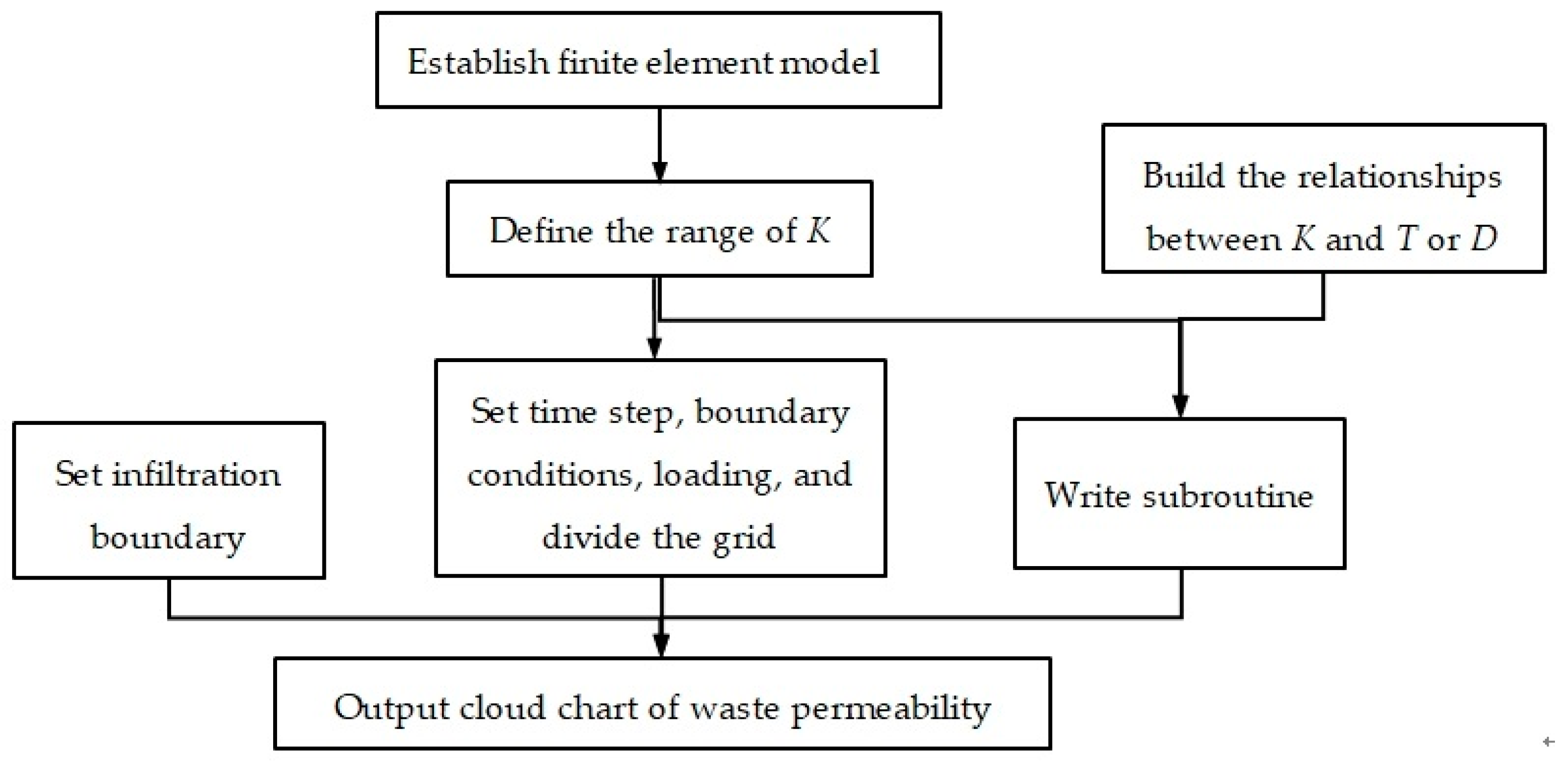
Xi’an has a semi-moist monsoon climate characterized by significant winds and four distinct seasons with moderate rainfall. In recent decades, the annual rainfall range has been recorded as 385.3–717.8 mm. Statistical data from the weather bureau indicates that there was high rainfall in 2011. For the purpose of seepage analysis, the average daily rainfall for each month of that year was considered as the load [50]. This resulted in a reduction in rainfall intensity on the landfill slope. When the rainfall intensity exceeded the waste permeability, the latter was used as the infiltration intensity. Conversely, when the rainfall intensity was lower, the actual rainfall was used as the infiltration intensity. The seepage parameters are presented in Table 1.
Obvious heterogeneity in permeability was found in the depth direction based on statistical analysis of waste characteristics, and the waste has been divided into the shallow, middle, and deep wastes by many scholars of landfill seepage analysis [26,48,52].
Based on the waste permeability test conducted on the landfill [26], the waste pile with a depth of 60 m was divided into six layers from shallow to deep, and the function distributions of permeability were also considered. The permeabilities of each layer (K1K6) were determined, and the functional distribution of permeability was also taken into consideration.
At the bottom of the 4th layer of waste, there is a drainage layer where leachate often escapes from the landfill slope. Therefore, it is necessary to establish a saturated-unsaturated seepage model, to set the drainage boundary in the corresponding location, and to define the rainfall load on top of each layer of waste. In the model, it is assumed that the rainfall distribution is uniform, and the rainfall intensity on the slope is reduced based on the slope ratio. Firstly, when filling the first layer at the bottom of the landfill, the upper layer is assumed to fail in the model. Then, the rainfall is loaded on top of the layer, and the seepage field of this waste layer is calculated. Secondly, when filling the second layer, this layer is reactivated while the upper layers still remain in a failed state. The preliminary result is used as the initial seepage field for this stage, the rainfall is loaded on top of the second layer, and the seepage field is calculated. Finally, the seepage field of the entire landfill is obtained by analogy.
The drainage system gradually clogs during the landfill process, which affects the leachate discharge from landfill. For clogging conditions, two clogging degrees were selected in Table 2.

3.4. Model

In landfills, it is common practice to layer and compact municipal solid waste (MSW). The typical process involves “transportation, unloading, paving, crushing, covering, and insect control”. Once a certain thickness of waste has been filled and crushed, a layer of loess is applied on top of the waste as a cover. This cover layer serves to slow down rainfall infiltration, reduce mosquito breeding, and mitigate odors.
We developed finite element software by writing a subroutine and built the relationships between the permeability of waste (K) and buried time (T) or depth (D). The proposed calculation process of the heterogeneous seepage model is shown in Figure 4.
When analyzing the seepage field of a working waste unit, it is necessary to consider both the bottom cover layer and the upper waste layer. Taking reference from the Xi’an Jiangcungou Landfill, a waste unit thickness of 10 m and a cover layer thickness of 0.3 m were chosen. To minimize the influence of model width on the seepage field, the model width was set to three times the waste unit thickness. A finite element model (FEM) was established for the waste layer, and a quadrilateral mesh was applied, as shown in Figure 5. Since the cover layer has a relatively thin thickness, its grid was refined to ensure convergence and to avoid numerical instability.
The 2-D finite element method (FEM) seepage model of the landfill was established based on the topographic map, as shown in Figure 6. During the early stage of landfilling, each layer had a height of 15 m, and a clay cover of approximately 0.3 m thickness was placed on top of the waste. To minimize leachate, a drainage layer was constructed when the filling reached an elevation of 543 m. Subsequently, waste with a height of 10 m and a clay cover of 0.3 m thickness were added until an elevation of 603 m was reached. For this calculation, the eight-node quadrilateral element and the pore fluid/stress grid type were adopted. The grids of the middle covering layers were refined to ensure the overall grid quality of the model, as depicted in Figure 7.
Numerical models were established, taking into account the landfill process, to establish the relationship between permeability and time. By defining material characteristics, boundaries, and loads, the cloud charts of waste saturation permeability were calculated and presented in Figure 8. The results indicate that waste permeabilities decrease continuously as the burial depth increases. The range of permeability falls between 1.200 × 10⁻⁴ m/day and 2.540 m/day, which aligns with practical observations.
The relationships between permeability, buried depth, and time were established, taking into account the landfill process and heterogeneity. The cloud charts depicting waste saturation permeability were presented in Figure 9. The results reveal variations in permeability within the waste, including the slope, at different depths. The range of permeability observed was between 1.178 × 10⁻⁴ m/day and 8.175 m/day. These findings are consistent with practical observations, indicating that the heterogeneity models are reasonable.

4. Results

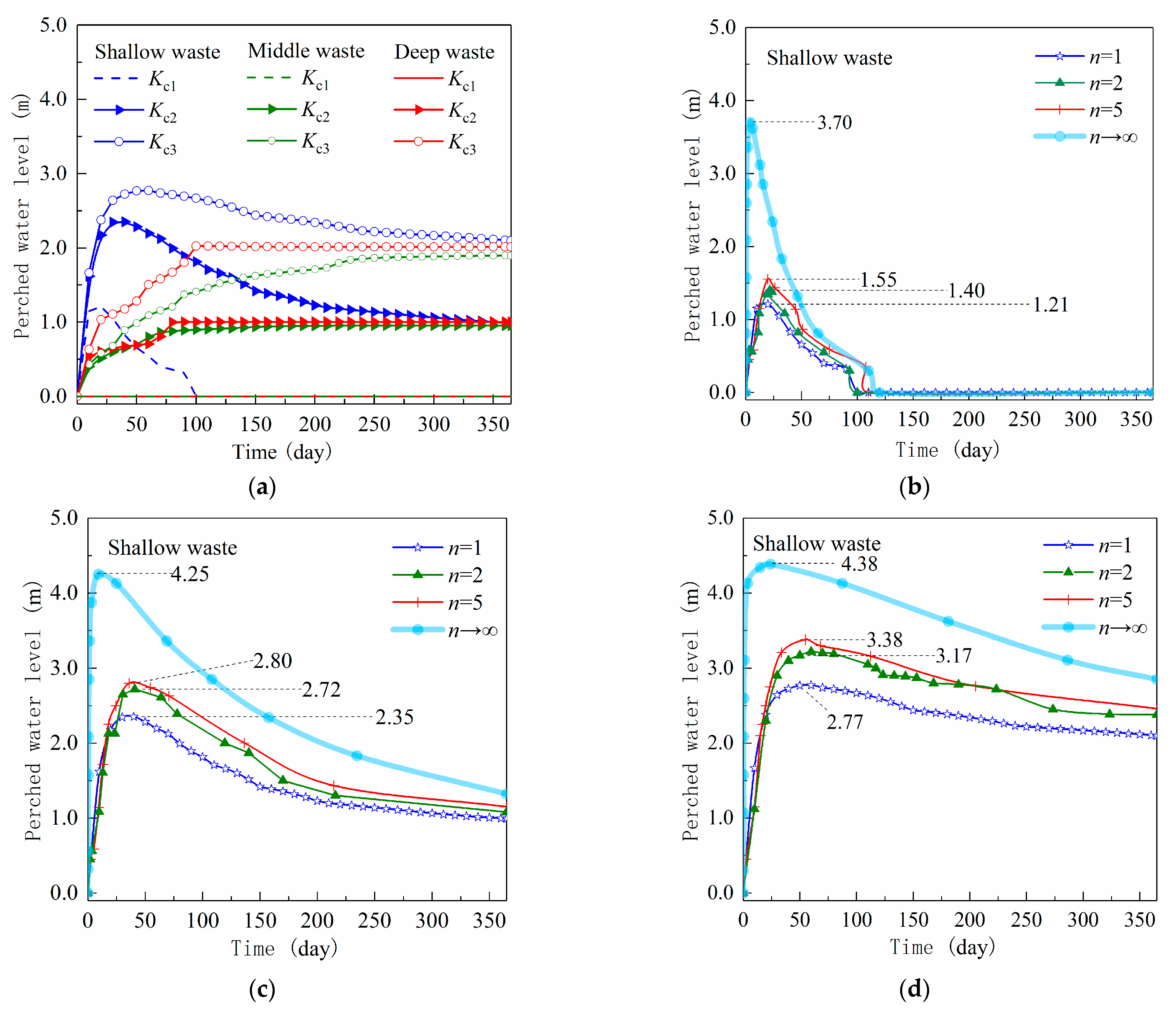
4.1. Seepage Results of Waste Unit

Through the seepage field analysis of the MSW unit in different permeabilities of cover layer and waste conditions, the change rules of perched water levels were shown in Figure 10a when the permeability of MSW unit was constant (n = 1). The analysis results indicated that perched water levels decreased as the permeability of the cover layer increased, particularly when the permeability of the cover layer was higher, and, in some cases, no perched water levels were observed. For instance, the stable water level was 0 in four different distributions of waste permeability (n = 1, n = 2, n = 5 and n→∞) when the permeability of the cover layer was Kc1. When the permeability of the cover layer was Kc2 or Kc3, leachate infiltrated and accumulated in the cover layer, gradually reaching an equilibrium position for forming stable levels. Due to the higher permeability of the shallow waste and the faster infiltration speed of leachate, the perched water level rises rapidly initially, decreases gradually, and finally tends toward a steady state under the effect of cover layer infiltration. For the middle and deep waste, the permeabilities are smaller and the infiltration speed of leachate is slower, meaning that the leachate accumulates slowly in the cover layer and rises gradually before it finally tends toward a steady state.
Considering the different permeabilities of the cover layer and the heterogeneity degrees of waste, the change rules of perched water levels are shown in Figure 10b–d, focusing on shallow waste. To compare and analyze the four different waste permeability distributions, it was observed that the growth of perched water levels was directly proportional to the increase in n. This is because waste permeabilities increase gradually from top to bottom in the waste unit, and leachate infiltrates and accumulates rapidly in the early stages. To compare and analyze the three different cover layers (Figure 10b–d), the results indicated that the maximum perched water level of heterogeneous waste (n→∞) was 2.49 m, 1.90 m, and 1.61 m higher than that of homogeneous waste (n = 1). In an actual landfill, if the maximum perched water level in each layer exceeds the levels observed under homogeneous conditions by 1.61 m to 2.49 m, it can significantly impact the pore pressures and overall stability of the landfill.

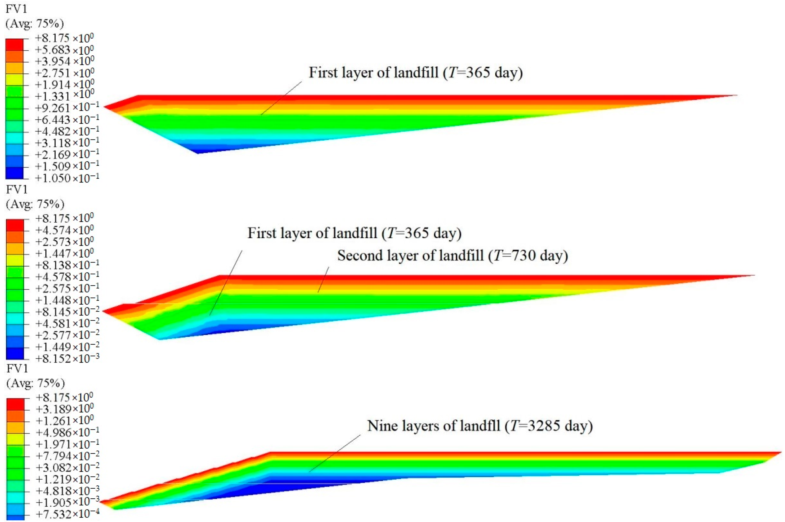
4.2. Seepage Results from the Xi’an Jiangcungou Landfill

To compare the variations in leachate levels among these schemes, five observation wells were set up to monitor the leachate levels, as shown in Figure 11. Well #1 was used to measure the perched water levels in the first and second layers, well #2 was designated for the second and third layers, well #3 was positioned in the fourth layer, well #4 was placed in the fifth layer, and well #5 was set up for the sixth-ninth layers. To evaluate the influence of the drainage layer on water levels, well #3 was strategically located near the drain to reflect the sensitivity of the declining water levels.
In Scheme 3, the leachate levels and pore pressure distributions of landfill when the ninth layer was finished are shown in Figure 12. It is evident that several perched water levels were present above the cover layers, with the exception of the first layer. This is because of effect of the prevention and accumulation of cover layers on leachate infiltration, and it is consistent with the previous research [12,48]. Therefore, the cover layer is identified as the primary factor influencing the leachate levels, which is consistent with the findings from the actual survey. The leachate levels decreased near the slope due to the presence of drainage boundaries in each layer adjacent to the slope. Furthermore, the pore pressure results indicate the presence of confined water heads in the first layer of landfill (Figure 12a). For reasons of analysis, it should be noted that rainfall impacted both the slope and the surface of the landfill, and there was no drainage system at the bottom of the landfill. Under the influence of rainfall infiltration and topographical conditions, both the fifth and sixth layers of the landfill in the upstream section generate confined water heads (Figure 12b). The results were consistent with the findings reported by Dang et al. [48].
The leachate distributions of the waste pile were depicted in Figure 13. The perched water level was denoted by well + layer. For instance, the perched water level in the first layer is represented as #1 + L1. In Scheme 3, the leachate level in the fourth layer ranged from 3.2 m to 5.6 m due to the lower permeability of the drainage layer. This leachate accumulation is a result of rainfall infiltration and accumulation on the landfill surface and slope. The drainage layer mainly had on impact on leachate levels in #2 + L3, #3 + L4, and #4 + L5, while having little impact on others. During the filling of the first layer, the perched water level rises with increasing rainfall, reaching a maximum confined water head of 17.6 m. The causes are that the drainage system was not installed early, the layers of perched water levels increase with the increasing of waste pile, and that the level of the third layer gradually decreases due to leachate infiltration of this layer and lower leachate recharge from the upper layers.
The leachate levels for all schemes were presented in Table 3. When the drainage layer becomes clogged, the leachate fails to discharge promptly and accumulates in the upper portion of the drainage layer, resulting in perched water levels. It can be observed that some leachate is discharged through the drain, leading to lower leachate levels (#3 + L4) in Schemes 1 and 2. In Schemes 3 and 4, the leachate level in the fourth layer of waste was high due to the low permeability of the drainage layer, and the saturation region extended until the seventh layer completed. These results demonstrated that embedding a drainage layer was one of the important measures to lower perched water levels in landfills. However, it had little impact on other layers due to the interception function of the middle covering layer on leachate. It was assumed that the drainage layer becomes completely clogged, resulting in the difficult discharge of leachate and the formation of persistent perched water.
Considering the landfill process and heterogeneity, the leachate levels are generated gradually in a top-down direction. In Scheme 4, the drainage layer is more clogged compared to Scheme 2, resulting in a maximum difference of 2.80 m in perched water levels. In Schemes 1 and 2, where the clogging degree is the same, the heterogeneous permeability of the waste, with higher permeability in the shallow layers, leads to a relatively high maximum perched water level in Scheme 2. Similarly, the maximum perched water level in Scheme 4 was higher than that in Scheme 3. These results highlighted the importance of setting appropriate boundaries, considering the clogging degree of the drainage layer, and accounting for the permeability distribution when calculating the landfill seepage field.
The maximum perched water levels of the four schemes were compared in Table 4. It was observed that all perched water levels were high, particularly in the deeper waste layers. Based on field investigations conducted by Chen et al. [53] on large-scale sanitary landfills, the leachate level was found to be slightly higher compared to foreign landfills, with a depth of approximately 3–5 m below the landfill surface. Taking into account the landfill process, the perched water level of the ninth layer was approximately 6.24–7.13 m in this study, aligning harmoniously with the aforementioned research findings. The lower perched water level of the fourth-ninth layers in Schemes 1 and 2 were caused by the larger permeability of the drainage layer compared to the levels in Schemes 3 and 4 considering the degree clogging. Taking into account the landfill process and heterogeneity of MSW permeability, the calculation results showed higher maximum perched water levels. For example, the perched water levels in the third-ninth layers were higher in Schemes 2 and 4 compared to Schemes 1 and 3. The calculation results for leachate levels were underestimated when considering the homogeneity condition. Therefore, when analyzing the seepage field, it is necessary to consider the landfill process and the heterogeneity of MSW permeability in order to ensure the safe operation of the landfill.

5. Discussion

Based on the seepage theory in the multi-layer soil, the heterogeneous transient seepage model was proposed. When the seepage characteristics were subdivided in the buried depth direction, the maximum perched water level was high, and it was not conducive to the safety and stability of the landfill. Thus, it is very important to set a reasonable permeability of waste in the numerical simulation of the landfill seepage field. However, the 2-D seepage model has limitations when simulating landfill leachate transportation. When the landfill is wide enough, the effect of landfill width on the model can be ignored.
The model proposed in this paper is aimed at addressing the heterogeneous permeability of landfill waste in the vertical direction. This issue has been mentioned in multiple sources in the literature [9,30,45,46,47], mostly using simplified models to simulate leachate water levels in landfills. However, these models cannot accurately reflect the actual situation, and the obtained results are not conducive to the safe operation of landfills. Because the permeability of landfill waste in the vertical direction of landfill waste is universal, when analyzing the leachate flow field in landfills, it is only necessary to obtain the distribution pattern of the permeability characteristics of the landfill waste. By using the model proposed in this paper, the leachate flow field in landfills can be simulated.
Through model analysis, it can be observed that it has been found that the general models tend to underestimate the perched water levels compared to the actual situation in landfills. In reality, landfills often have multiple layers of perched water tables, and the calculated results tend to be more conservative than the actual conditions. The advantage of the model proposed in this paper is its ability to accurately simulate the variations in leachate in landfills.
This model can also be used to simulate the landfilling process of waste in landfills, as well as to simulate the migration of leachate during the clogging process of the drainage layer during landfill operation.

6. Conclusions

In this study, the seepage characteristics of waste were studied, and then the heterogeneous seepage model was established. Furthermore, the influence of waste permeability distribution and clogging of drainage layer on landfill seepage field were analyzed. Finally, based on the heterogeneous seepage characteristics of the Xi’an Jiangcungou Landfill, the heterogeneous seepage model was applied to a practical project to research the law of leachate transport in the landfill. The following conclusions have been drawn:
(1)
Combined with the actual project of the Xi’an Jiangcungou Landfill, the heterogeneous seepage model was established to research the formation and transportation of the perched water level in landfill. When considering the landfill process and heterogeneous permeability, the maximum perched water levels of each layer were higher than the levels of homogeneous waste, and the differential values were about 0.08–1.88 m, which were not good for the stability of landfill.
(2)
The arrangement of the drainage layer significantly reduces the perched water level in the MSW layer. The maximum perched water level of the MSW layer was approximately 4.90–5.84 m in the landfill. During the initial stage of precipitation, this study observed a maximum difference of about 2.80 m in the perched water level of the MSW layer under two different drainage layer clogging conditions. However, the drainage layer has little impact on the perched water level in other MSW layers due to the interception of leachate by the covering layer. Therefore, it is recommended to install drainage pipes or implement shaft measures in all MSW layers of the landfill to reduce the perched water level.
(3)
Through finite element analysis, it was determined that the leachate water levels in the Xi’an Jiangcungou Landfill were high, with several layers of perched water levels. This can be attributed to the absence of drainage pipes initially buried in the initial landfill. Confined water heads were observed in the first layer of the MSW, while a higher unsaturated zone was present below the fourth layer of the MSW due to the presence of the drainage layer. The perched water level at the landfill surface layer was found to be approximately 6.24–7.13 m, which closely aligns with the actual survey data and references, thus validating the reliability of the proposed model in this study. These research findings not only offer technical support but also provide a theoretical foundation for the control of leachate levels and the safe operation of the landfill.

Author Contributions

Writing—original draft, investigation, writing—review and editing, R.Y.; writing—review and Editing, J.R.; writing—review and editing, X.C.; writing—review and editing, K.Y. All authors have read and agreed to the published version of the manuscript.

Funding

This study was financially supported by the Natural Science Basic Research Program of Shaanxi [Program No. 2022JQ–426] and the National Natural Science Foundation of China [grant number 52209147].

Data Availability Statement

The data used to support the findings of this study are included within the article.

Acknowledgments

We would like to thank the Xi’an Municipal Solid Waste Management Bureau for providing engineering information for this research. The authors are also grateful to the editor and the anonymous reviewers for their insightful comments and suggestions.

Conflicts of Interest

Author Kun Yang was employed by the company China Gezhouba Group No. 3 Engineering Co., Ltd. The remaining authors declare that the research was conducted in the absence of any commercial or financial relationships that could be construed as a potential conflict of interest.

References

  1. Gao, W. Research on Time-Dependent Constitutive Models for Municipal Solid Waste and Service Performance of Landfills. Ph.D. Thesis, Zhejiang University, Hangzhou, China, 2018. [Google Scholar]
  2. Li, Z.J.; Huang, Y.L.; Ma, J.L.; Chen, M.S. Hidden trouble investigation and safety operation measures of waste landfill: Taking a waste landfill safety case as example. Environ. Sanit. Eng. 2017, 25, 91–96. [Google Scholar]
  3. Huang, Y.; Fan, G. Engineering geological analysis of municipal solid waste landfill stability. Nat. Hazards 2016, 84, 93–107. [Google Scholar] [CrossRef]
  4. Qian, X.D.; Koerner, R.M. Stability analysis when using an engineered berm to increase landfill space. J. Geotech. Geoenviron. Eng. 2009, 135, 1082–1091. [Google Scholar] [CrossRef]
  5. Qian, X.D. Limit equilibrium analysis of translational failure of landfills under different leachate buildup conditions. Water Sci. Eng. 2008, 1, 44–62. [Google Scholar]
  6. Liu, S.; Fan, S.G.; Sun, Z.H.; Zhang, X.X. Analysis of metal ion content in different treatment stages of landfill leachate. Appl. Chem. Ind. 2018, 47, 1304–1307. [Google Scholar]
  7. Wang, Y.Y. Study on the Impact of Leachate from Jiangcungou Landfill on the Surrounding Ecological Environment in Xi’an City. Master’s Thesis, Changan University, Xi’an, China, 2008. [Google Scholar]
  8. Zhang, C.; Liang, B.; Liu, L.; Wan, Y.; Zhu, Q.C. Determination of unsaturated hydraulic properties of seepage flow process in municipal solid waste. Water 2021, 13, 1059. [Google Scholar] [CrossRef]
  9. Yang, R.; Xu, Z.G.; Chai, J.R. A review of characteristics of landfilled municipal solid waste in several countries: Physical composition, unit weight and permeability coefficient. Pol. J. Environ. Stud. 2018, 27, 2425–2435. [Google Scholar] [CrossRef]
  10. Dixon, N.; Jones, D.R.V. Engineering properties of municipal solid waste. Geotext. Geomembr. 2005, 23, 205–233. [Google Scholar] [CrossRef]
  11. Hong, Y.; Xia, J.Q.; Thompson, J.R.; Flower, R.J. Urban construction and demolition waste and landfill failure in Shenzhen, China. Waste Manag. 2017, 63, 393–396. [Google Scholar]
  12. Yang, J.K. Research on Unsaturated Flow and Preferential Flow in Municipal Solid Waste. Master’s Thesis, Shanghai University, Shanghai, China, 2020. [Google Scholar]
  13. Zeiss, C.; Uguccioni, M. Mechanisms and patterns of leachate flow in municipal solid waste landfills. J. Environ. Syst. 1994, 23, 247–270. [Google Scholar] [CrossRef]
  14. He, H.J. Study on Leachate and Landfill Gas Generation, Transportation and Induced Slope Instability in Municipal Solid Waste Landfill. Ph.D. Thesis, Zhejiang University, Hangzhou, China, 2018. [Google Scholar]
  15. Zhang, W.J.; Lin, W.A.; Chen, Y.M. Pore pressure monitoring and slope stability analysis of a waste landfill. Chin. J. Rock Mech. Eng. 2010, 29, 3629–3632. [Google Scholar]
  16. Xu, X.B.; Zhan, L.T.; Chen, Y.M.; Beaven, R.P. Intrinsic and relative permeabilities of shredded municipal solid wastes from the Qizishan landfill, China. Can. Geotech. J. 2014, 51, 1243–1252. [Google Scholar] [CrossRef]
  17. Vrancken, C.; Longhurst, P.J.; Wagland, S.T. Critical review of real-time methods for solid waste characterisation: Informing material recovery and fuel production. Waste Manag. 2017, 61, 40–57. [Google Scholar] [CrossRef] [PubMed]
  18. Han, B.; Imhoff, P.T.; Yazdani, R. Field application of partitioning gas tracer test for measuring water in a bioreactor landfill. Environ. Sci. Technol. 2007, 41, 277–283. [Google Scholar] [CrossRef] [PubMed]
  19. Capelo, J.; de Castro, M. Measuring transient water flow in unsaturated municipal solid waste—A new experimental approach. Waste Manag. 2007, 27, 811–819. [Google Scholar] [CrossRef] [PubMed]
  20. Kim, Y.C.; Cramer, J.A.; Booksh, K.S. Investigation of a fiber optic surface plasmon spectroscopy in conjunction with conductivity as an in situ method for simultaneously monitoring changes in dissolved organic carbon and salinity in coastal waters. Analyst 2011, 136, 4350–4356. [Google Scholar] [CrossRef]
  21. Grellier, S.; Reddy, K.; Gangathulasi, J.; Peters, C. Electrical resistivity tomography imaging of leachate recirculation in orchards hills landfill. In Proceedings of the SWANA (Solid Waste Association of North America)’s 44th Annual International Solid Waste Exposition (WASTECON 2006), Charlotte, NC, USA, 19–21 September 2006. [Google Scholar]
  22. Zhang, W.J.; Zhan, L.T.; Chen, Y.M.; Wei, H.Y. Unsaturated-saturated seepage analysis of municipal solid wastes. Chin. J. Rock Mech. Eng. 2007, 26, 87–93. [Google Scholar] [CrossRef]
  23. Zhang, W.J. Experimental and Numberical Study on Water/Leachate Transport in Landfill of Municipal Solid Waste. Ph.D. Thesis, Zhejiang University, Hangzhou, China, 2007. [Google Scholar]
  24. Zhang, Z.; Wu, D.Z.; Zhang, L.F.; Yan, L. Study on the permeability and the permeable mechanism of the municipal solid waste. Energy Educ. Res. 2014, 32, 1517–1524. [Google Scholar]
  25. Chen, Y.M.; Ke, H. Engineering characteristics of municipal solid wastes and geotechnical problems of landfills. Eng. Mech. 2005, 22, 119–126. [Google Scholar]
  26. Yang, R.; Xu, Z.G.; Chai, J.R.; Qin, Y. Permeability test and slope stability analysis of municipal solid waste (MSW) in Jiangcungou Landfill, Shaanxi, China. J. Air Waste Manag. 2016, 66, 655–662. [Google Scholar] [CrossRef]
  27. Feng, S.J.; Gao, K.W.; Chen, Y.X.; Li, Y.; Zhang, L.M. Geotechnical properties of municipal solid waste at Laogang Landfill, China. Waste Manag. 2017, 63, 354–365. [Google Scholar] [CrossRef] [PubMed]
  28. Li, M.Y.; Jae, H.K.; Xu, Q.Y. Review about hydraulic conductivity of landfilled waste. Environ. Eng. 2014, 32, 80–88. [Google Scholar]
  29. Wang, W.F. Laboratory Research on Saturated Hydraulic Conductivity of Municipal Solid Waste under Different Degradation Age. Master’s Thesis, Zhejiang University, Hangzhou, China, 2013. [Google Scholar]
  30. Liu, Z. Experimental Study on Hydraulic Conductivity of Municipal Solid Waste and Analysis of Pumping Vertical Well. Master’s Thesis, Zhejiang University, Hangzhou, China, 2010. [Google Scholar]
  31. Ke, H.; Wang, W.F.; Wei, C.C.; Chen, Y.M.; Zhan, L.T. Experimental study on saturated hydraulic conductivity of MSW under different conditions. J. Zhejiang Univ. (Eng. Sci.) 2013, 47, 1164–1171. [Google Scholar]
  32. Qiu, Z.H.; He, C.M.; Zhu, B.J.; Chen, H.L. Investigations of water transport in valley–type MSW landfills and their stabilities subjected to various rainfall patterns. Rock Soil Mech. 2012, 33, 3151–3170. [Google Scholar]
  33. Wang, H.T.; Yin, Y. Numerical simulation of moisture movement in landfill bioreactors under the condition of leachate recirculation. Environ. Sci. 2003, 24, 66–72. [Google Scholar]
  34. Zhang, W.J. Analyses on a high leachate mound in a landfill of municipal solid waste in China. Environ. Earth Sci. 2013, 70, 1747–1752. [Google Scholar] [CrossRef]
  35. Jang, Y.S.; Kim, Y.W.; Lee, S.I. Hydraulic properties and leachate level analysis of Kimpo metropolitan landfill, Korea. Waste Manag. 2002, 22, 261–267. [Google Scholar] [CrossRef]
  36. Xu, Q.; Powell, J.; Tolaymat, T.; Tolaymat, T.G. Seepage control strategies at bioreactor landfills. J. Hazard. Toxic Radioact. Waste 2013, 17, 342–350. [Google Scholar] [CrossRef]
  37. Dai, Z.L.; Huang, Y.; Jiang, F.H.; Huang, M.S. Modeling the flow behavior of a simulated municipal solid waste. Bull. Eng. Geol. Environ. 2016, 75, 275–291. [Google Scholar] [CrossRef]
  38. Childs, E.C.; Collins-George, N. The permeability of porous materials. Proc. R. Soc. A 1950, 1066, 392–405. [Google Scholar]
  39. Richards, L.A. Capillary conduction of liquids through porous mediums. Physics 1931, 1, 318–333. [Google Scholar] [CrossRef]
  40. Mao, C.X. Seepage Computation Analysis and Control; China Water Power Press: Beijing, China, 1990; pp. 5–20. [Google Scholar]
  41. Gray, W.G.; Miller, C.T. On the algebraic and differential forms of Darcy’s equation. J. Porous Media 2011, 14, 33–50. [Google Scholar] [CrossRef]
  42. Peng, H.; Chen, S.H. Finite element analyses of unstable seepage in saturated-unsaturated rock. J. Hydrodyn. 2002, 17, 253–259. [Google Scholar]
  43. Li, X.; Gao, J.; Wang, Z.L.; Li, L. Three-dimensional calculation of seepage flow in saturated-unsaturated soil. Shuili Xuebao 1992, 11, 63–80. [Google Scholar]
  44. Fei, K.; Zhang, J.W. Application of ABAQUS in Geotechnical Engineering; China Water Power Press: Beijing, China, 2009; pp. 184–216. [Google Scholar]
  45. Shen, L. Liquid Depth Study and Stability Analysis of Municipal Solid Waste Landfill. Master’s Thesis, Zhejiang University, Hangzhou, China, 2011. [Google Scholar]
  46. MHURDPRC (Ministry of Housing and Urban-Rural Development of the People’s Republic of China). Technical Code for Geotechnical Engineering of Municipal Solid Waste Sanitary Landfill; CJJ176-2012; Construction Industry Press: Beijing, China, 2012. [Google Scholar]
  47. Jie, Y.X.; Danzeng, D.Z.; Wei, Y.F. Study on the permeability of municipal solid waste. Geotech. Eng. Tech. 2005, 19, 307–310. [Google Scholar]
  48. Dang, M.R.; Chai, J.R.; Xu, Z.G.; Qin, Y.; Cao, J.; Liu, Y.F. Soil water characteristic curve test and saturated–unsaturated seepage analysis in Jiangcungou municipal solid waste landfill, China. Eng. Geol. 2020, 264, 105374. [Google Scholar] [CrossRef]
  49. Lai, J.B.; Wang, Q.J. Comparison of soil water retention curve model. J. Soil Water Conserv. 2003, 17, 71–74. [Google Scholar]
  50. NBSPRC (National Bureau of Statistics of the People’s Republic of China). China Statistical Yearbook 2016; Statistics Press: Beijing, China, 2016. [Google Scholar]
  51. Shi, W.; Chai, X.L. Experiments on loess as intermediate cover in landfills in northwest China. J. Shanghai Univ. (Nat. Sci.) 2016, 22, 505–514. [Google Scholar]
  52. Zhang, W.J.; Chen, Y.M.; Zhan, L.T. Seepage and stability analysis of landfills. In Proceedings of the 2nd National Conference on Geotechnical and Engineering, Wuhan, China, 29–31 October 2006. [Google Scholar]
  53. Chen, Y.M.; Lan, J.W.; Li, Y.C.; Zhan, L.T.; Ke, H. Development and control of leachate mound in MSW landfills. Chin. J. Rock Mech. Eng. 2014, 33, 154–163. [Google Scholar] [CrossRef]
Figure 1. Seepage flow of heterogeneous multi-layer waste.
Water 15 04115 g001
Figure 2. The relationship between flow velocity and pore pressure [45].
Water 15 04115 g002
Figure 3. Seepage parameters of the MSW landfill. (a) The distribution of MSW saturated permeability [7]; (b) the relationships between saturation and pore pressure.
Water 15 04115 g003
Figure 4. The basic flow chart to establish the heterogeneous seepage model.
Water 15 04115 g004
Figure 5. The model and mesh of the waste unit.
Water 15 04115 g005
Figure 6. Topographic map of the Xi’an Jiangcungou Landfill.
Water 15 04115 g006
Figure 7. The model of the Jiangcungou Landfill.
Water 15 04115 g007
Figure 8. Cloud chart of waste saturation permeability considering the landfill process (unit: m/day).
Water 15 04115 g008
Figure 9. Cloud chart of waste saturation permeability considering the landfill process and heterogeneity of MSW permeability (unit: m/day).
Water 15 04115 g009
Figure 10. Changing rules of the perched water levels in the waste unit. (a) n = 1; (b) Kc1 = 5.0 × 10⁻⁸ m/s; (c) Kc2 = 1.0 × 10⁻⁸ m/s; (d) Kc3 = 5.0 × 10⁻⁹ m/s.
Water 15 04115 g010
Figure 11. Locations of observation wells.
Water 15 04115 g011
Figure 12. Leachate levels and pore pressure distributions of the waste pile in Scheme 3.
Water 15 04115 g012
Figure 13. Leachate distributions of the waste pile in Scheme 3.
Water 15 04115 g013
Table 1. Seepage parameters.
ParametersDetails
RainfallMonth1, 2, 3, 4, 5, 6, 7, 8, 9, 10, 11, 12
Daily rainfall (mm)0.02, 0.53, 0.28, 0.58, 2.63, 1.09, 2.52, 2.72, 9.48, 1.40, 2.17, 0.22
Saturated permeability (m/s)MSW pile k s a t = 4.024 1.018 × 10 1 D 2.815 × 10 5 D 2 + 7.077 × 10 - 6 D 3   [26]
K1, K2, K3, K4, K5, K6
Waste dam1.0 × 10–9
Foundation1.0 × 10–9
The middle covering layer8.37 × 10–10 [51]
Note: ① D is the buried depth of waste (m); ② K1, K2, K3, K4, K5, and K6 are the values of k s a t when D is 5 m, 15 m, 25 m, 35 m, 45 m, and 55 m, respectively.
Table 2. Schematic design.
Clogging Degree of Drainage LayerPermeability Distribution of Waste LayerScheme
k d 1 = 8.64 m/dayHomogeneity1
Heterogeneity2
k d 2 = 4.80 × 10⁻⁴ m/dayHomogeneity3
Heterogeneity4
Table 3. The leachate levels of all schemes at different times.
Time (Day)365730109514601825
Leachate level (m)Scheme 1#1 + L112.9013.7015.1715.3015.80
#2 + L2/8.136.305.705.70
#2 + L3//5.924.703.70
#3 + L4///4.613.10
#4 + L5////5.18
Scheme 2#1 + L112.7012.9013.6013.8014.25
#2 + L2/8.717.307.307.20
#2 + L3//7.925.203.70
#3 + L4///5.323.00
#4 + L5////3.90
Scheme 3#1 + L112.9013.6015.1715.3015.80
#2 + L2/6.806.306.005.90
#2 + L3//6.605.003.70
#3 + L4///5.204.90
#4 + L5////5.50
Scheme 4#1 + L112.8013.7013.4014.8015.80
#2 + L2/8.937.507.108.10
#2 + L3//8.245.506.40
#3 + L4///5.865.80
#4 + L5////3.40
Table 4. The maximum perched water levels of all schemes (Unit: m).
Observation Well#1#2#3#4#5
Waste Layer1, 223456789
The maximum perched water levels (m)Scheme 117.608.946.824.905.185.526.236.676.24
Scheme 217.608.717.925.327.067.327.447.926.96
Scheme 317.608.866.725.675.535.836.376.806.43
Scheme 417.608.948.245.847.337.567.487.937.13
Disclaimer/Publisher’s Note: The statements, opinions and data contained in all publications are solely those of the individual author(s) and contributor(s) and not of MDPI and/or the editor(s). MDPI and/or the editor(s) disclaim responsibility for any injury to people or property resulting from any ideas, methods, instructions or products referred to in the content.

