Article

Development of a High-Rotational Submersible Pump for Water Supply

by
Vladyslav Kondus
,
Ivan Pavlenko
*,
Oleksandr Kulikov
and
Oleksandr Liaposhchenko
Faculty of Technical Systems and Energy Efficient Technologies, Sumy State University, Rymskogo-Korsakova St., 40007 Sumy, Ukraine
*
Author to whom correspondence should be addressed.
Water 2023, 15(20), 3609; https://doi.org/10.3390/w15203609
Submission received: 19 September 2023 / Revised: 5 October 2023 / Accepted: 9 October 2023 / Published: 16 October 2023
(This article belongs to the Special Issue Design and Optimization of Fluid Machinery)

Abstract

:
Submersible pumps are the leading electricity consumers in centralized water supply systems. Considering the cost structure of the life cycle of pumping equipment, the main costs should include investment costs, electricity costs during operation, and costs of repairing pumping equipment. Considering the growing cost of electricity in the world, the cost of manufacturing pumping equipment is significantly increasing, which in turn causes an increase in its price. The key factor in increasing the competitiveness of such equipment on the market is its modernization with the achievement of a higher level of energy efficiency with a simultaneous reduction in cost due to a reduction in weight and dimension parameters. In the research, a significant increase in the head from 15 m to 65 m of the submersible pump stage was achieved by increasing the rotation frequency from 3000 rpm to 6000 rpm and designing the pump for this rotation frequency. As a result, the pump head, created by the flowing part with the basic stage (eight pieces), can be provided by the pump using only two designed stages. It creates the prerequisites for reducing the mass of the pump from 200 kg to 45 kg, or by 77.5%. Also, in designing the pump, energy efficiency was increased from 74.6% (for the existing pump) to 79.4% (by 5% for the developed pump). The research results made it possible to significantly contribute to reducing the cost of the life cycle of the submersible pump installation.

1. Introduction

In centralized water supply systems, an essential element is water intake, which must function as a reliable water source in quantity and quality [1]. At the same time, water intake from natural reservoirs (e.g., lakes, rivers) or an artesian well can be used as a source of water supply [2].
Considering the quality of the liquid, artesian water has a much higher level of purity than that taken by water intake from open natural reservoirs [3].
Borehole pumps are mainly designed to supply water from artesian wells (Figure 1). They are widely used at water intake stations and other enterprises where water supply from deep mines is necessary [4]. Pumps of this type are also actively used in the gas and oil industry [5].
Pumps for supplying water from artesian wells are installed directly in the pipes, so they have a limited diametrical overall size. This is the main difficulty in their design because the limited diameter of the impeller is the main factor in the limited amount of pressure it creates [6]. As a result, pumps of this type are designed with a multistage design [7].
Depending on the configuration, the pump sections can have 5–10 or even more stages in case a high head is required [8]. When the impeller rotates, the liquid from the first stage is transferred to the second and then to the third [9]. Such a principle allows the increase in the kinetic energy of the liquid, correspondingly increasing the pressure [10].
The appropriate brand is selected to achieve the optimal pressure-supply value based on the tasks set before the unit. Submersible-type pumps are equipped with a safety valve that regulates the water column in the event of a sudden engine stop, facilitates restarting, and protects the rotation of the blades in the opposite direction [11].
The dimensions of submersible pumps, depending on the functionality, vary up to three meters or more, the mass reaches more than half a ton, and the head is more than 600 m. The pump casing is made of cast iron or corrosion-resistant steel. Smaller analogs of submersible pumps are used in agriculture and even for household needs in homesteads or provide drinking well water to the house.
Submersible pumps [12] are the primary electricity consumers in centralized water supply systems. Considering pumping equipment’s life cycle cost structure, the main costs should include investment (development, manufacturing, installation, start-up, and adjustment works), electricity during operation, and repairing pumping equipment.
The characteristics of the submersible pump unit of the ECW type (Figure 2) are presented in Table 1 [13].
ECV pumps are marked as follows. E means driven by a submersible electric motor, C means centrifugal pump, W means designed for water supply, the first number is the diameter of the casing pipe into which the pump is installed, the second number is the pump flow rate in m3/h, and the third number is the pump head in meters.
According to Eurostat data on the electricity cost dynamics in the European market during 2022, it should be noted that considering the growing cost of electricity in the world, the cost of manufacturing pumping equipment increases significantly [14], which in turn causes an increase in its price [15]. Taking this into account, the key factor in increasing the competitiveness of such equipment on the market is its modernization, achieving a higher energy efficiency of the pump than that of analogs existing on the pump equipment market with a simultaneous reduction in the production cost due to a reduction in its weight and overall dimensions [16].
Due to the above-mentioned analysis, the research aims to reduce the life cycle cost of submersible pumps and pumping units based on them.
To realize this aim, the following research tasks were set:
(1)
Development of the structural scheme of the pump and design of the elements of its flowing part with reduced weight and dimensions;
(2)
Selection of the numerical research method, initial conditions, and turbulence model;
(3)
Performing a numerical study of hydrodynamic processes in the elements of the flowing part of the developed pump in order to ensure a high level of energy efficiency and obtain the resulting energy characteristics of the pump;
(4)
Analysis of research results.
Achieving this aim will make it possible to implement measures to achieve several UN Sustainable Development Goals [17], e.g., clean water and proper sanitation; affordable and clean energy; and industry, innovation, and infrastructure.

2. Materials and Methods

As a pump for modernization, the ECW 10-63-150 pump was chosen, the operating parameters of which are given in Table 1. For its modernization and replacement, a new pump was designed with an increased frequency of shaft rotation up to 6000 rpm. Due to the increased frequency of rotation, the impeller can create a significantly higher head [18]. This will make it possible to reduce the number of stages, influencing the reduction in mass and dimensions. The main requirement of the pump is that the diameter size should not exceed 260 mm to ensure operation as a replacement for the existing fleet of this pump.
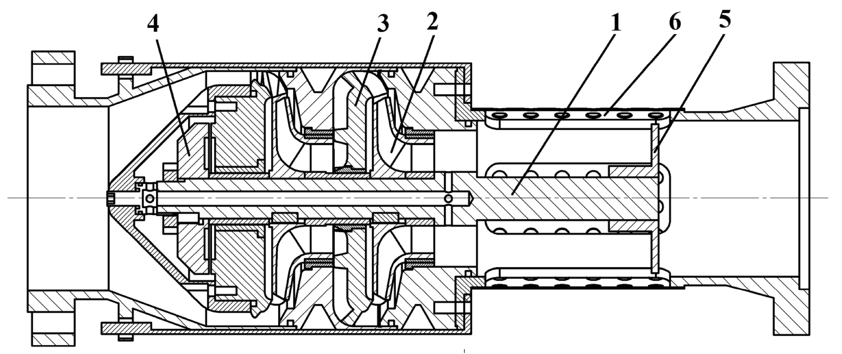
The newly designed pump (Figure 3) has two stages. At the same time, the existing currently in use ECW 10-63-150 pumps use a flowing part with 8 stages [19]. The developed design of the pump made it possible to reduce the weight of the pump from 200 kg (for the existing ECW 10-63-150 pump) to 45 kg, that is, by 77%.
The operating position of the pump is vertical. The pump has a shaft 1 on which stages consisting of an impeller 2 and a guide device 3 are located. For unloading the residual axial force, an automatic balancing device 4 is used at different operation modes [20,21] for pump operation with different values of the flow rate parameter from zero to maximum when the pump’s efficiency is maximum. At the end of the shaft, there is a coupling 5, which allows for connecting the pump shaft with the motor shaft.
Shaft 1 causes the impeller 2 to rotate. The liquid from the underwater device enters the impeller 2 through the grid 6. After that, it enters the guide vanes 3, which redirect the fluid flow to the next stage. As the fluid passes through all pump stages, it gains energy and leaves the pump. Part of the liquid enters the hydraulic heel, where axial force is unloaded. The spent liquid is returned to the supply through the drain hole in the pump shaft, an essential feature of the developed pump. The through shaft allows for increasing the pressure at the entrance to the first stage of the pump, which significantly improves the cavitation properties of the pump [22]. The total length of the pump without an electric motor is 550 mm, 72.5% less than the existing analog.
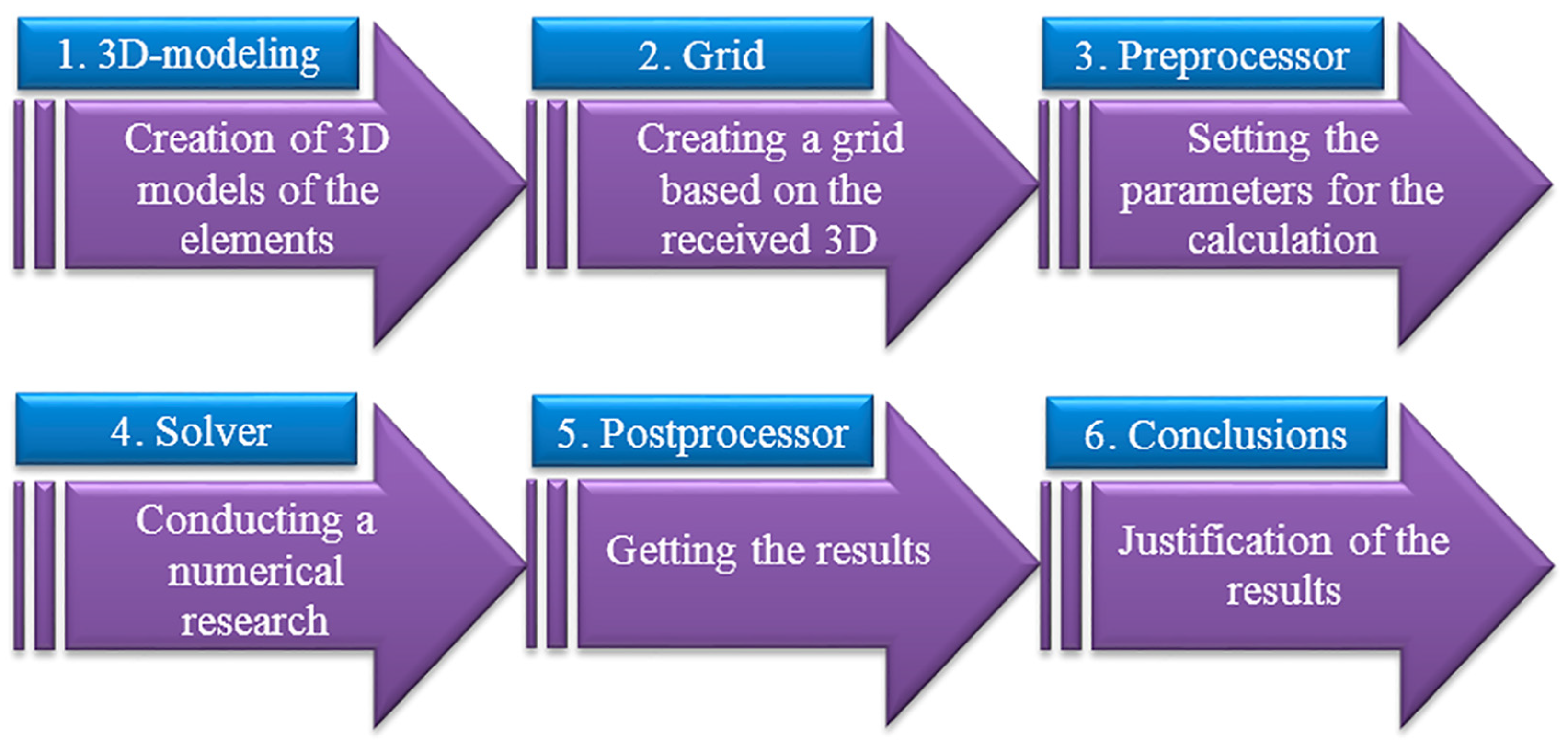
According to the developed design scheme, the design of 3D models of the elements of its flowing part, the centrifugal impeller, and the guide vanes was performed in SolidWorks 2018. Numerical research of the flow parameters of the pumped liquid was carried out using the ANSYS CFX 13.0 software complex in the flow rate range from Q = 0.05·QBEP to Q = 1.8·QBEP (where BEP is the best efficiency point, the operational flow rate when the best efficiency η is reached). To ensure the correct operation of the numerical research in ANSYS CFX, elongated sections are made near the inlet and outlet of each element of the flow part. This software product has proven to be accurate in modeling the operating process of dynamic pumps. In particular, the research error does not exceed 5%, which fully meets the requirements for the accuracy of engineering calculations [23]. The scheme of the research is given in Figure 4.
The ANSYS CFX was used based on the numerical solution method of the fundamental hydromechanics laws. It was repeatedly tested in solving the problems of pump design, and the discrepancy between the numerical and physical modeling results does not exceed 5%; therefore, this software product is suitable for solving the stated research problem.
The modeling of turbulent fluid flow is performed using Reynolds equations (i, j = 1–3) [24,25]:
t ρ U i + x i ρ U i U j = p x j + x i μ U i x j + U j x j + f i ,
f i = ρ 2 ω × u + ω × ω × r ,
p t + x i ρ U j = 0 ,
where xi and xj are coordinate axes; ui and uj are velocity components; p is pressure; t is time; fi are mass forces; ω is the vector of the angular velocity of rotation; r is the radius vector; ρ is the density of the pumped liquid, kg/m3; and μ is the dynamic viscosity, m2/s.
While modeling turbulent flows in the Navier–Stokes equation, the instantaneous velocity is replaced by the sum of the Reynolds averaged velocity and the pulsating component of the velocity. The dependence (1) takes the following form [26]:
t ρ U i + x i ρ U i U j + x j ρ U i U j = p x j + x i μ U i x j + U j x j + f i ,
where U i and U j are time-averaged velocity values; and U i and U j are pulsating components of velocities.
In the course of the research, the ANSYS CFX software was used to record the values of the flow rate Q (m3/h), the torque on the pump impeller M (N·m), and the fluid velocity at the outlet and inlet of the pump v2 and v1 (m/s). The values of head H (m), useful power Nu (W), power consumed by the pump Nc (W), and the efficiency η were calculated depending on the following parameters:
H = z 2 z 1 + p 2 p 1 ρ g + v 2 2 v 1 2 2 g ;
N u = ρ g Q H ;
N c = M ω ;
η = N u N c = ρ g Q H M ω ,
where z2 and z1 are the height of the outlet and inlet levels of the pump, m; ω is the angular velocity of the impeller rotation, rad/s.
The design of calculation meshes of the pump’s flowing part elements was performed in the software component ICEM CFD 13.0 [27]. The wall layer is made as follows. The thickness of the first layer was 0.04 mm. The sizes of subsequent layers increased exponentially with an index of 1.5. The number of layers in the wall layer is 7. In the region of the wall layer, the cells have a prismatic shape, and in the region of the rest of the flow, they have the shape of a tetrahedron.
The calculation area (Figure 5) was created in the CFX-Pre 19.0 package.
The operating environment was water with a temperature of 20 °C. The mode was turbulent. To conclude the Reynolds equations, the standard k-ε [28] turbulence model was used, which has proven itself well in conducting studies of the flow in the flow part of centrifugal pumps [29].
The value of the variable y+, which characterizes the thickening of the mesh near the walls, was within 20 < y+ < 100, which had an exact match with the error of engineering measurements in previous studies of centrifugal pumps during field tests [30].

3. Results

The analysis of the research results was carried out in the CFX-Post 19.0 environment. The following drawings were made to study the qualitative picture of fluid movement through the pump’s flow part and make corrections to its structural elements.
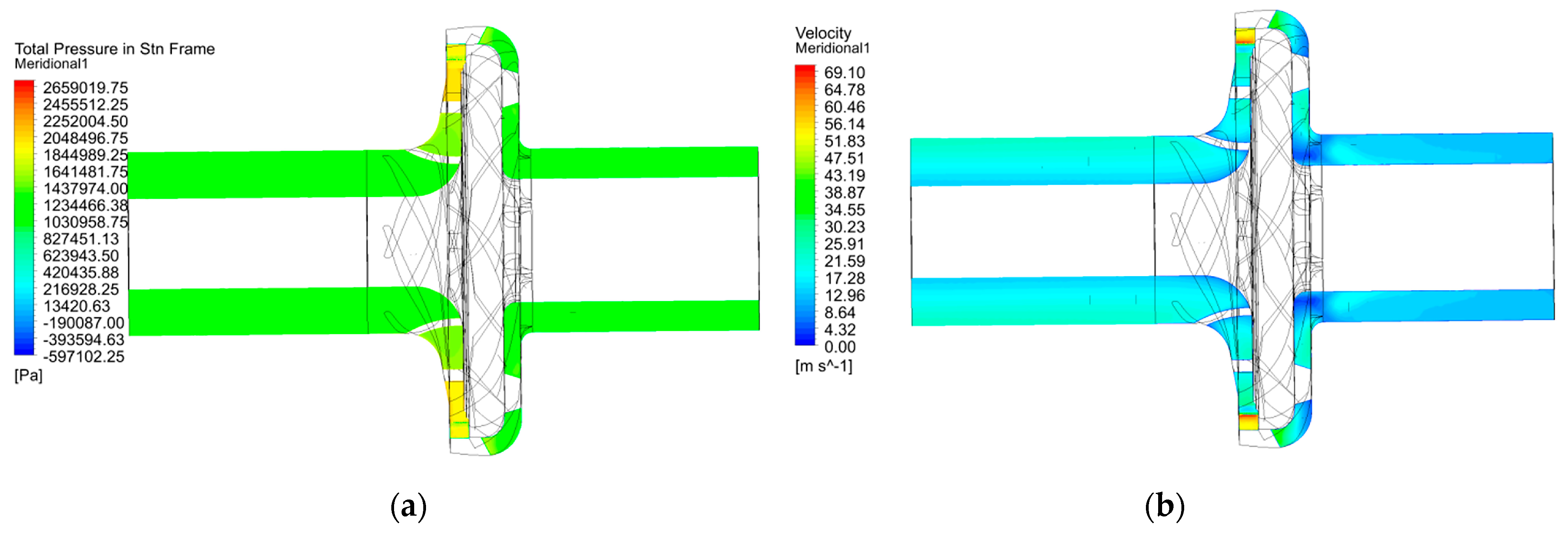
In the beginning, modeling of the basic stage of the ECW 10-63-150 pump (Figure 6) was carried out to obtain its characteristics and the liquid flow pattern in the intervane channels of the impeller and guide vanes.
Analysis of the qualitative picture of the relative velocity distribution (Figure 6b) during the rotation of the impeller proves the efficiency and its effect on the head created behind the impeller [31]. The existing zones of slightly reduced (blue color) relative velocity have a pronounced character and are explained by vortex formation and pressure changes.
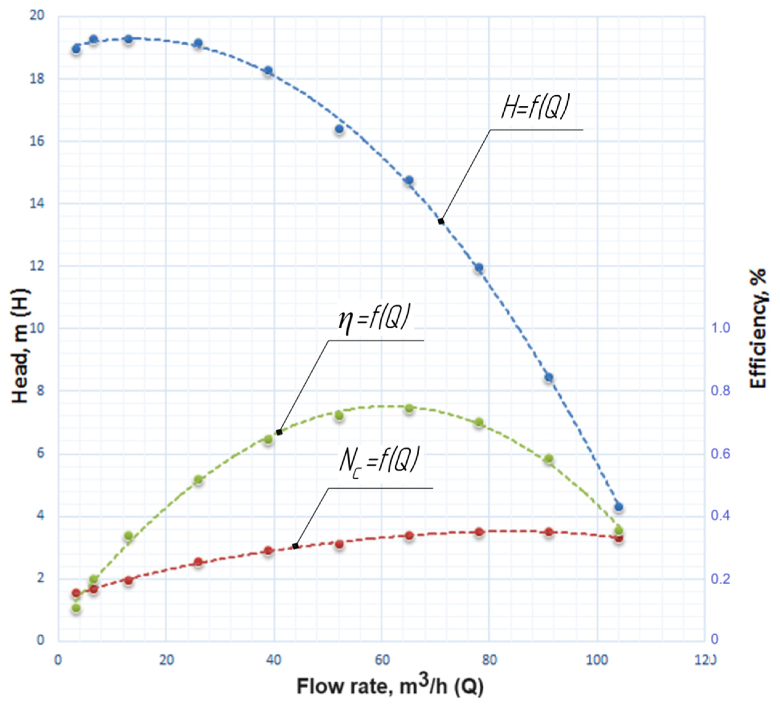
Table 2 shows the pump parameters of the stage in different operation modes obtained from the initial model of the ECV 10-63-150 pump using the above-mentioned numerical simulation approach. It is essential to see how the pump functions not only at the BEP (best efficiency point) but also in other operating modes (Q < QBEP, Q > QBEP). This is explained by the fact that the pump can function in different operating modes. A decrease in the operating parameters (head, power, efficiency) on the modes (Q < QBEP, Q > QBEP) can lead to a deterioration of the pump operating conditions, in particular on the starting modes (cavitation phenomena, surging), which reduces the service life of the pump and increases the risk of premature failure of its design elements. Taking this into account, we present the pump’s operating parameters in a wide supply range, Q = 0.05–1.8 QBEP, for a complete analysis of the obtained results.
For the next research stage, using the design methodology according to [32], a stage consisting of an impeller and a guide vane with an increased rotation frequency of 6000 rpm was developed (model 01).
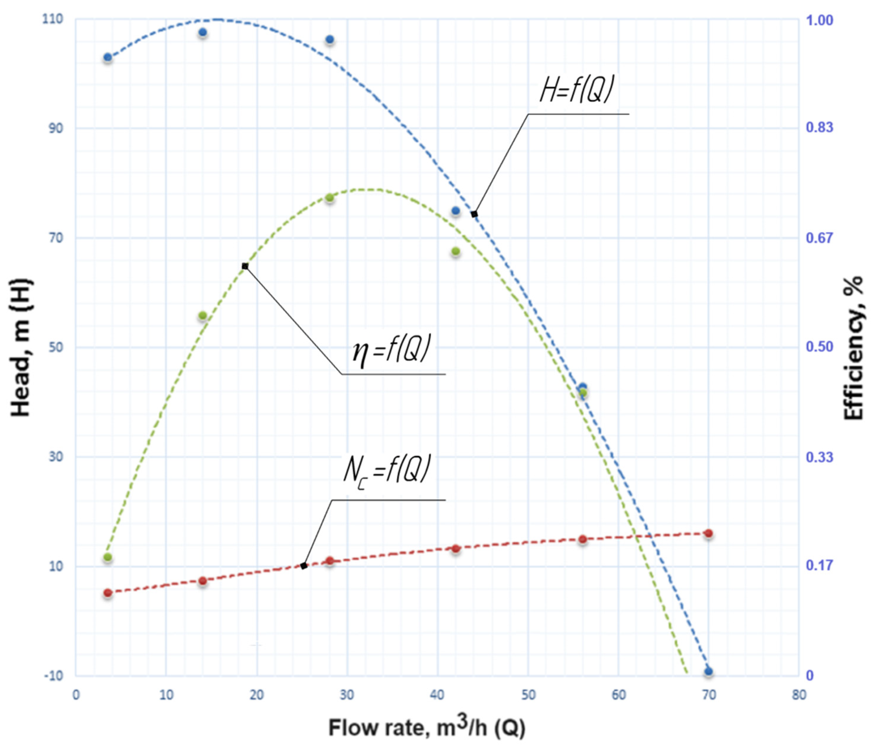
Figure 7 shows the characteristics of the stage in different operating modes obtained using the quasilinear regression approach [29]. Figure 8 shows the flowing part’s pressure and relative velocity distributions (model 01). The red line shows the dependence of the consumed power Nc on the flow rate of this design pump Q. The green line shows the dependence of the pump efficiency on the flow rate of this design pump Q, and the blue line shows the dependence of the pump head H on the flow rate of this design pump Q.
Analysis of the qualitative picture of the relative velocity distribution during its rotation inside the guide vanes shows that there are reduced (blue color) and increased (red color) relative velocity zones with a pronounced character. This is explained by forming a vortex due to the separation of the liquid flow from the part’s surface and the change in pressure in these areas [16]. The significant vortices occur in the outlet channel of the guide vanes, which decrease the entire stage’s efficiency. Therefore, it can be concluded that the guide vanes do not perform their function correctly due to the significant narrowing of the passage channel and the friction of the viscous layers of liquid between themselves [33]. The guide vanes create additional hydraulic losses at increased rotation frequency despite the design methodology. At the same time, the function of converting kinetic energy into potential energy is only partially fulfilled, as shown by an additional literature review on this problem [34].
The relative velocity distribution in the stage proves the need for its improvement and the correctness of the selection of the guide vanes. Unfortunately, existing design methods for today are not designed for the design of the flowing part of submersible pumps with a rotation frequency of more than 3000 rpm.
Due to narrowed guide vanes (Figure 8), the operating point shifted to the area of lower flow rates at increased rotation frequency. At the same time, the operating point had the following parameters: the flow rate was about 28 m3/h and the head was about 106 m with the highest efficiency value equal to 73% (Table 3).
The next step in the research was the improvement of the guide vanes to reduce hydraulic losses. As a result, a vaneless guide vane (model 02) was created with a channel width of 15 mm [35] in the transfer and inlet channels to prevent flow compression and vortex formation (Figure 9).
The total pressure and relative velocity distributions in the developed pump stage’s flowing part with vaneless guide vanes (model 02) are presented in Figure 10.
Analysis of the qualitative picture of the relative velocity distribution (Figure 10b) during the impeller rotation proves the correctness of the direction of improvement of the guide vanes. There are zones of slightly reduced (blue color) and increased (red color) relative velocity after the fluid leaves the guide vanes, which have a strongly pronounced character and are explained by the mixing of liquid layers among themselves [36]. This design shifted the optimum point to the region of increased flow rates.
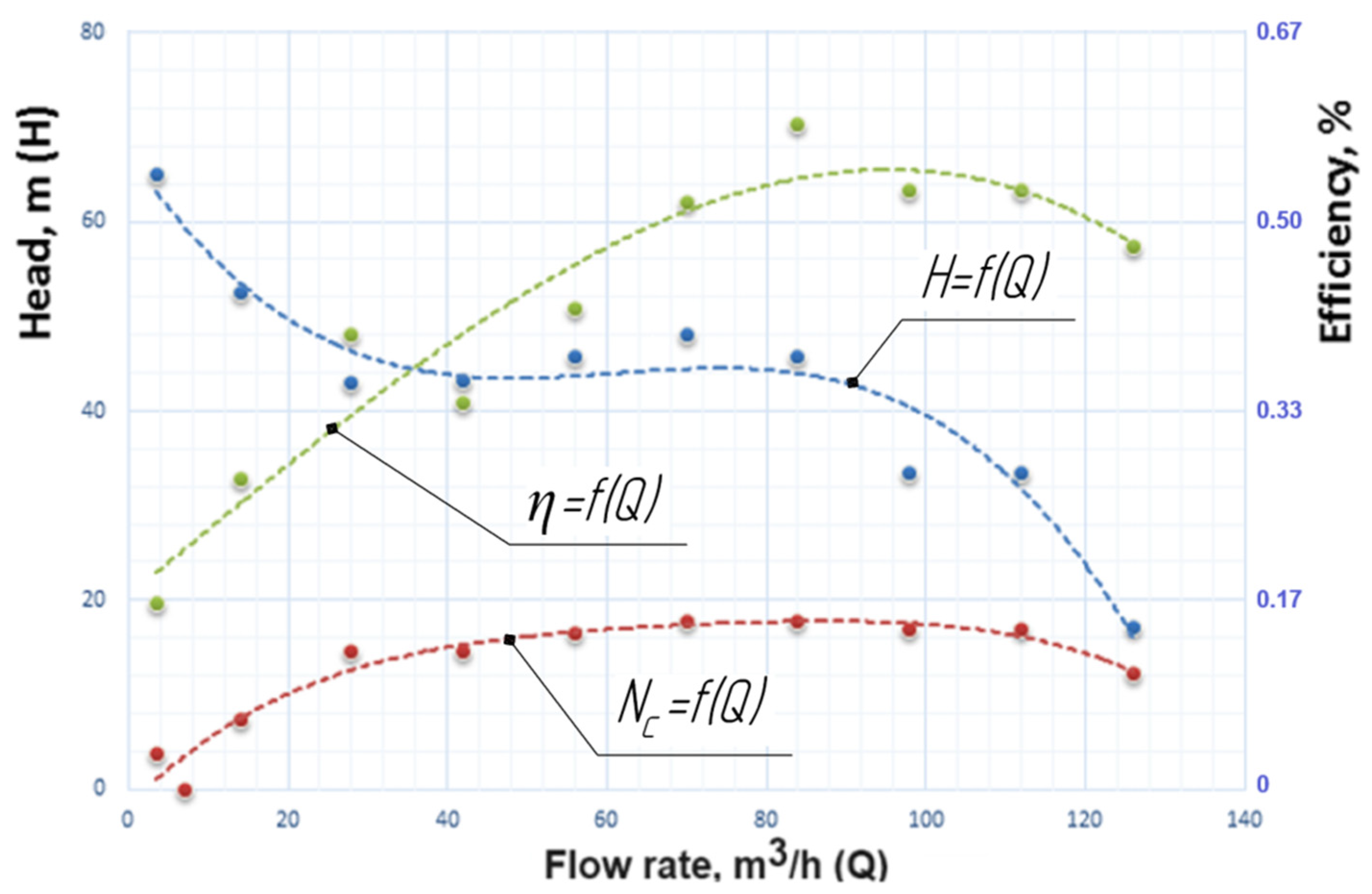
Due to the expansion of the guide vanes, the operating point (Table 4) had the following characteristics: the flow rate was about 84 m3/h and the head was about 46 m with the highest efficiency value equal to 59%.
The pressure characteristic (Figure 11) is constantly falling, which is a satisfactory result from the point of view of pump operation.
At the next stage of the research, the guide vanes were improved by adding vanes with constant thickness to equalize the pressure characteristics of the stage (model 03).
Analysis of the qualitative picture of the relative velocity distribution (Figure 12) during the impeller rotation proves the correctness of the improvement of the guide vanes.
The main problem was the poor inflow onto the vanes of the guide vanes, which led to additional hydraulic losses, characterized by zones of slightly reduced (blue color) relative velocity in the intervane channels of the guide vanes.
According to the research results, the appropriate pressure characteristic of the stage was obtained (Table 5).
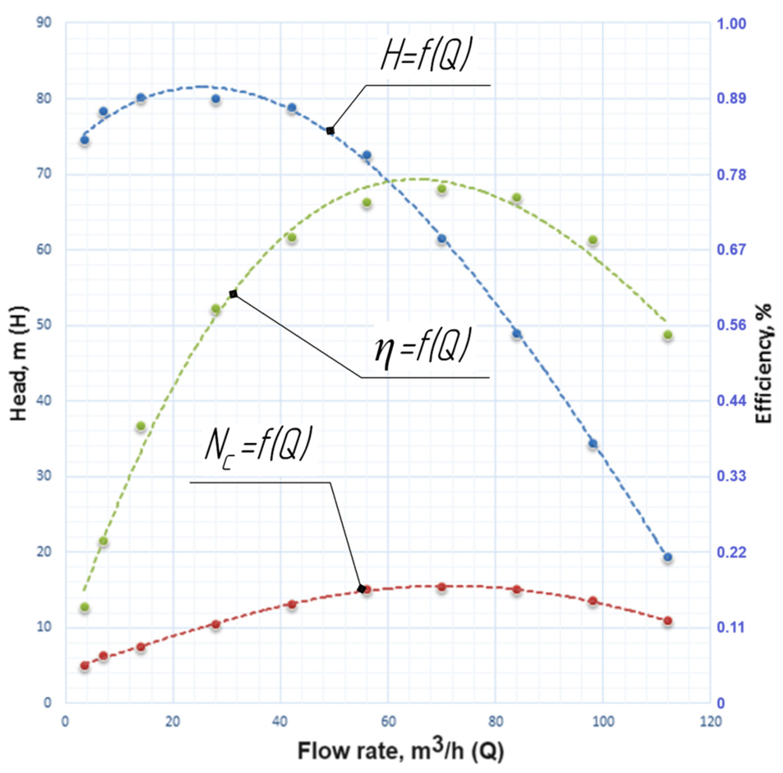
The operating point shifted towards slightly increased flow rates and had the following characteristics (Figure 13): the flow rate was about 70 m3/h and the head was about 62 m with the highest efficiency value equal to 76%. In this model of the guide vanes, efficiency characteristics close to the basic level were obtained, and the head values increased significantly.
The last step of the research was the narrowing of the transfer and inlet channels of the guide vanes from 15 mm to 10 mm to build the correct axisymmetric flow in the meridional section of the guide vanes (model 04).
Analysis of the qualitative picture of the relative velocity distribution (Figure 14) proves the correctness of the guide vanes’ design.
The distribution of fluid in the stage is qualitative. There are no zones of significantly reduced (blue color) and increased (red color) relative velocity in the intervane channels of the guide vanes.
In this stage model (model 04), there is an increase in both the head and the pump’s efficiency (Table 6).
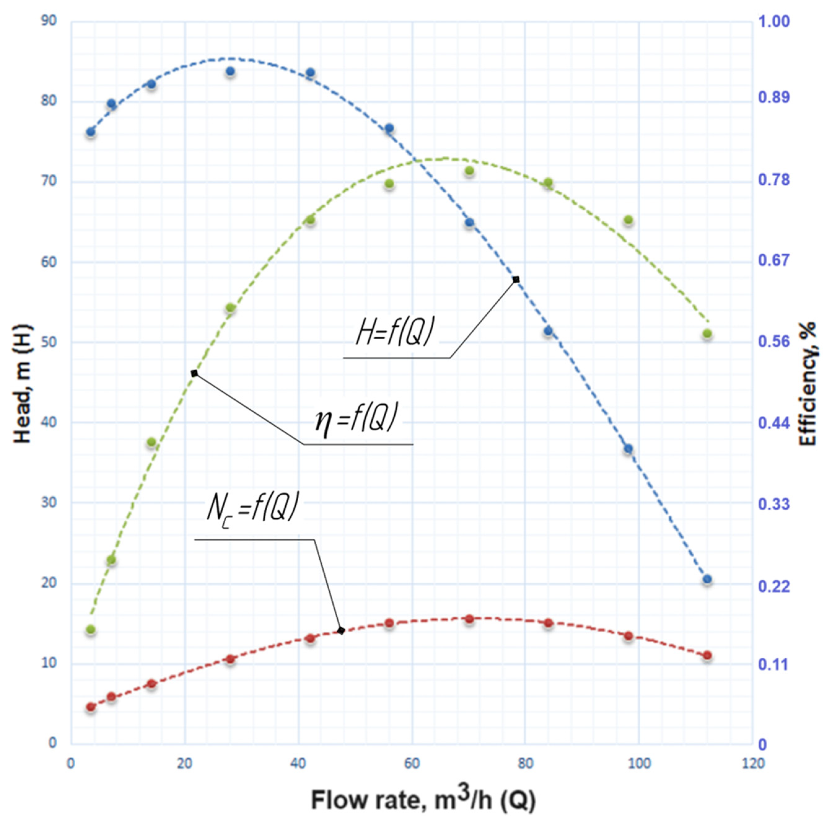
The operating point remained unchanged compared to the previous version (flow rate equal to 70 m3/h), the head increased slightly to the value of 65 m, and thanks to the correctly designed guide vanes, a high efficiency level, about 80%, was achieved. The head characteristic (Figure 15) of the stage has a drop in the delivery range from 0 to 28 m3/h, which does not affect the pump’s performance because the standard regulates the possibility of operating the pump in the operation range of (0.7–1.2)·Qopt [37].
Based on the research results, the electric pump unit ECW 10-65-150 was developed, characterized by increased energy efficiency indicators and head characteristics concerning existing analogs (Table 7).

4. Discussion

Given the obtained results, a significant increase in the head was achieved from 14.75 m of the basic stage to 65.04 m of the developed stage (model 04) of the pump, which is 440% more. Thus, the pump head, which is created by the flowing part with a basic stage (eight pieces), can be provided by a pump using only two designed stages (model 04) [38].
According to the research results, the pump’s weight was reduced from 200 kg to 45 kg, or 77.5%.
The energy efficiency (nominal mode) of the developed stage (model 04) is the highest of all the studied stages (79.42%). Also, it is 5% higher than that of the basic stage.
The power consumption (nominal mode) of the developed stage (models 03 and 04) is almost the same (15.56 kW and 15.62 kW, respectively). However, the head of the 04 model is 3.5 m (or 5.4%) higher than that of the 03 model.
The pictures of the relative velocity distribution in the intervane channels of the centrifugal impeller and the guide vanes (Figure 14b) prove the high quality of the design of the flowing part of the pump unit, the correctness of the installation angles of the blades, and the correct selection of their number (Figure 14a).
According to the calculations, the head characteristic of the stage was built (Figure 15), with the help of which we can see that the pressure at the calculation point Q = 70 m3/h is 65 m, and the efficiency is 80%.
The standard [37] establishes the following requirements for the operation of pumping equipment. Short-term operation of the pumping equipment in the operating range Q = (0.7–1.2)·QBEP and long-term operation in supply modes Q = (0.9–1.1)·QBEP is allowed. In this case, the flow rate at QBEP means the mode of operation of the pump, in which the maximum value of efficiency η is reached.
For long-term operation of pumping equipment, we will obtain the following range from 63 m3/h to 77 m3/h. With such values, we can obtain such a range of the head and efficiency. At a point with a flow rate of 63 m3/h, we will obtain a head of 71 m and an efficiency of 80%. At a point with a flow rate of 77 m3/h, we will obtain a head of 59 m and an efficiency of 79%.
For short-term operation of pumping equipment, we will obtain the following range from 49 m3/h to 84 m3/h. With such values, we can obtain such a range of the head and efficiency. At a point with a flow rate of 49 m3/h, we will obtain a head of 80 m and an efficiency of 77%. At a point with a flow rate of 84 m3/h, we will obtain a head of 22 m and an efficiency of 78%. Having obtained a good efficiency characteristic, we can increase the pump’s operating range during its long-term operation.
Submersible pumps can differ depending on the depth of water’s rise or the diameter of the well. The smaller the diameter of the well, the more stages need to be used to raise the liquid from the source, affecting the mass and dimensional parameters of the pumping unit.
Using this pump on all wells can increase uniformity, standardization, reliability, and the number of spare parts stored in the warehouse.
The main advantages of the research results are as follows. Firstly, an increase in efficiency of the developed pump by 4.87% compared to the existing analog has been achieved. Secondly, there is a 67.5% reduction in the weight and overall dimensions of the developed pump, which will lead to a significant reduction in the cost of the pump in comparison with an existing analog. Moreover, the use of the proposed approach made it possible to reduce the cost and prevent the need for manufacturing and full-scale testing of intermediate models of the developed pump (models 01, 02, and 03).
The limitation of the study is the need to replace pump elements, which requires additional investment costs for the modernization of already installed pumps.
Further studies will be aimed to prove the results of numerical studies by carrying out a full-scale test at the Laboratory of Hydrodynamic Drives and Installations. It is also planned to conduct a more in-depth study of the flow pattern in the flowing part of the developed pump stage model (model 04) and the integral characteristics of the pump based on it. It is also planned to manufacture and test the pump using the developed model of the pump stage (model 04).

5. Conclusions

During the research, the flowing part of the submersible pump for water intake stations was developed, and it was characterized by increased energy characteristics due to the increased frequency of the shaft rotation. The proposed structural scheme is fundamentally new for submersible pumps with a two-stage flowing part structural scheme.
Based on the developed design diagram of the ECW 10-65-150 pump, 3D models of the pump flowing part (impeller, guide vanes) and the liquid pumped were created in the SolidWorks software environment. Using the ANSYS CFX software complex, numerical research of hydrodynamic processes was performed in the 3D model of the elements of the developed pump’s flowing part, which made it possible to obtain the maximum possible indicators of the pump’s energy efficiency and ensure its increased head capacity due to the increased frequency of the shaft rotation. The stage parameters in the nominal operating mode are as follows: the flow rate equals Q = 70 m3/h, the head is equal to H = 65.04 m, and efficiency is η = 79.42%.
Due to the increase in the rotation frequency of the rotor, a significant increase in the stage’s head was achieved from 14.75 m (basic model) to 65.04 m (developed model 04), which creates the prerequisites for reducing the number of stages in the pump from eight pieces down to two pieces, as well as a significant reduction in material capacity from 200 kg to 45 kg, or by 67.5% of the pump.
From the point of view of energy efficiency, an increase in efficiency η compared to the existing analog (basic model) has been achieved by up to 4.87%, which will significantly reduce its energy consumption.
Introducing this pump to operate on water intakes will increase the unification and standardization of pumping equipment. In addition, it will reduce the cost of the life cycle of the pump installation based on the developed pump due to a significant reduction in investment costs and electricity costs during the pump operation compared to the base model.

Author Contributions

Conceptualization, V.K.; methodology, V.K. and I.P.; software, I.P. and O.K.; validation, O.L.; formal analysis, V.K. and O.L.; investigation, V.K., I.P., O.K. and O.L.; resources, O.K.; data curation, I.P.; writing—original draft preparation, V.K. and O.K.; writing—review and editing, I.P.; visualization, O.K.; supervision, O.L.; project administration, O.L.; funding acquisition, I.P. All authors have read and agreed to the published version of the manuscript.

Funding

The Ulam NAWA Program partially funded the research, grant number BPN/ULM/2022/1/00042.

Data Availability Statement

The data are available from the corresponding author upon reasonable request.

Acknowledgments

The research was partially realized within the project “Development of design solutions and layout schemes of a parametric series of high-speed energy-efficient well pumps for the needs of enterprises in the field of critical infrastructure” (No. 2022.01/0096) of the National Research Foundation of Ukraine. The authors appreciate the Public Union “Sumy Machine-Building Cluster of Energy Efficiency” and the International Association for Technological Development and Innovations (IATDI) for their support while conducting the research.

Conflicts of Interest

The authors declare no conflict of interest.

References

  1. Kumar, J.; Gopi, S.; Amirthagadeswaran, K. Redesigning and numerical simulation of gating system to reduce cold shut defect in submersible pump part castings. Proc. Inst. Mech. Eng. Part E J. Process Mech. Eng. 2023, 237, 971–981. [Google Scholar] [CrossRef]
  2. Ramez, A.; Al-Hakimi, W.; Perozo, N.; Jaeger, P. Real-time liquid rate and water cut prediction from the electrical submersible pump sensors data using machine-learning algorithms. ACS Omega 2023, 8, 12671–12692. [Google Scholar] [CrossRef]
  3. Aydin, H.; Merey, S. Design of Electrical Submersible Pump system in geothermal wells: A case study from West Anatolia, Turkey. Energy 2021, 230, 120891. [Google Scholar] [CrossRef]
  4. Tong, S.; Zhao, H.; Liu, H.; Yu, Y.; Li, J.; Cong, F. Multi-objective optimization of multistage centrifugal pump based on surrogate model. J. Fluids Eng. 2020, 142, 011101. [Google Scholar] [CrossRef]
  5. Al-Mudhafar, W.J.; Wood, D.A.; Al-Obaidi, D.A.; Wojtanowicz, A.K. Well placement optimization through the triple-completion gas and downhole water sink-assisted gravity drainage (TC-GDWS-AGD) EOR process. Energies 2023, 16, 1790. [Google Scholar] [CrossRef]
  6. Kondus, V.; Gusak, O.; Yevtushenko, J. Investigation of the operating process of a high-pressure centrifugal pump with taking into account of improvement the process of fluid flowing in its flowing part. J. Phys. Conf. Ser. 2021, 1741, 012012. [Google Scholar] [CrossRef]
  7. Firatoglu, Z.A.; Alihanoglu, M.N. Investigation of the effect of the stages number, the impeller outlet width, and the impeller outlet angle on the performance of an industrial electric submersible pump. J. Fluids Eng. 2022, 144, 081203. [Google Scholar] [CrossRef]
  8. Lingom, P.M.; Song-Manguelle, J.; Betoka-Onyama, S.P.; Nyobe-Yome, J.M.; Doumbia, M.L. A Power Quality Assessment of Electric Submersible Pumps Fed by Variable Frequency Drives under Normal and Failure Modes. Energies 2023, 16, 5121. [Google Scholar] [CrossRef]
  9. Liu, Z.; Jiang, B.; Zuo, J.; Pan, Y. Influence of clocking position between impeller and guide vane on the performance of well submersible pump. J. Liaoning Tech. Univ. 2023, 42, 198–206. [Google Scholar]
  10. Arocena, V.M.; Abuan, B.E.; Reyes, J.G.T.; Rodgers, P.L.; Danao, L.A.M. LAM Numerical investigation of the performance of a submersible pump: Prediction of recirculation, vortex formation, and swirl resulting from off-design operating conditions. Energies 2021, 14, 5082. [Google Scholar] [CrossRef]
  11. Bhattacharjee, P.; Hussain, S.A.I.; Dey, V. Failure mode and effects analysis for submersible pump component using proportionate risk assessment model: A case study in the power plant of Agartala. Int. J. Syst. Assur. Eng. Manag. 2023, 14, 1778–1798. [Google Scholar] [CrossRef]
  12. Malonda, P.; Ngoma, G. Numerical Investigation of a High-Capacity Vertical Submersible Two-Stage Pump and Realization of an Experimental Test Bench for Determining the Strains and the Stresses on a Pump Shaft. In Proceedings of the 13th International Conference on Simulation and Modeling Methodologies, Technologies and Applications SIMULTECH, Lisbon, Portugal, 12–14 July 2023; pp. 393–400. [Google Scholar] [CrossRef]
  13. ECW-10. Submersible Pumps. Available online: https://www.ECW-ukraine.com.ua/ectv-10-serii (accessed on 1 October 2023).
  14. Kondus, V.; Sotnyk, M.; Sokhan, A.; Antonenko, S.; Rybalchenko, V. Assessment of the Life Cycle Cost and Improvement of the Parametric Series of Torque-Flow Pumps. In Advanced Manufacturing Processes V; Tonkonogyi, V., Ivanov, V., Trojanowska, J., Oborskyi, G., Pavlenko, I., Eds.; Springer: New York, NY, USA, 2023. [Google Scholar]
  15. Monte Verde, W.; Kindermann, E.; Biazussi, J.L.; Estevam, V.; Foresti, B.P.; Bannwart, A.C. Experimental investigation of the effects of fluid viscosity on electrical submersible pumps performance. SPE Prod. Oper. 2023, 38, 1–19. [Google Scholar] [CrossRef]
  16. Glovatskii, O.; Ergashev, R.; Nasirova, N.; Rashidov, J.; Kholbutaev, B. Experimental tests of submersible vane pumps. E3S Web of Conf. 2023, 401, 05065. [Google Scholar] [CrossRef]
  17. Plotkin, J.; Levchenko, N.; Shyshkanova, G.; Levchenko, S. Development of energy enterprises in the context of green transformation. Int. J. Eng. Sci. (Ukraine) 2023, 10, G22–G33. [Google Scholar] [CrossRef]
  18. Antonenko, S.; Sapozhnikov, S.; Kondus, V.; Chernobrova, A.; Mandryka, A. Creation a universal technique of predicting performance curves for small-sized centrifugal stages of well oil pump units. J. Phys. Conf. Ser. 2021, 1741, 012011. [Google Scholar] [CrossRef]
  19. Bulgarelli, N.; Biazussi, J.; Verde, W.; Perles, C.; Castro, M.; Bannwart, A. Experimental investigation on the performance of Electrical Submersible Pump (ESP) operating with unstable water/oil emulsions. J. Petrol. Sci. Eng. 2021, 197, 107900. [Google Scholar] [CrossRef]
  20. Pavlenko, I.; Trojanowska, J.; Gusak, O.; Ivanov, V.; Pitel, J.; Pavlenko, V. Estimation of the reliability of automatic axial-balancing devices for multistage centrifugal pumps. Period. Polytech. Mech. Eng. 2019, 63, 52–56. [Google Scholar] [CrossRef]
  21. Han, Y.; Bai, L.; Du, D.; Shi, W.; Zhou, L. Effects of tip clearance on energy performance of three-stage electrical submersible pump. Geoenergy Sci. Eng. 2023, 226, 211696. [Google Scholar] [CrossRef]
  22. Arocena, V.M.; Abuan, B.E.; Reyes, J.G.T.; Rodgers, P.L.; Danao, L.A.M. Reduction of Entrained Vortices in Submersible Pump Suction Lines Using Numerical Simulations. Energies 2020, 13, 6136. [Google Scholar] [CrossRef]
  23. Pavlenko, I.; Ciszak, O.; Kondus, V.; Ratushnyi, O.; Ivchenko, O.; Kolisnichenko, E.; Kulikov, O.; Ivanov, V. An Increase in the Energy Efficiency of a New Design of Pumps for Nuclear Power Plants. Energies 2023, 16, 2929. [Google Scholar] [CrossRef]
  24. Yang, Y.; Wu, S.; Wang, C.; Jiao, W.; Ji, L.; An, C.; Ge, J. Effect of effuser throat diameter on the internal flow structure and energy characteristics of the jet pump. Energy Rep. 2023, 9, 2075–2086. [Google Scholar] [CrossRef]
  25. Dykas, S.; Wilk, A. Determination of the flow characteristic of a high-rotational centrifugal pump by means of CFD methods. Task Q. 2008, 12, 245–253. [Google Scholar]
  26. Zhang, Y.; Han, J.; Huang, B.; Zhang, D.; Wu, D. Excitation force on a pump-jet propeller: The effect of the blade number. Ocean Eng. 2023, 2811, 114727. [Google Scholar] [CrossRef]
  27. Andrusiak, V.O.; Lugova, S.O.; Medvid, S.A.; Tkach, P.Y.; Rudenko, A.A. Effect of front impeller seal leakages on centrifugal stage characteristics. J. Phys. Conf. Ser. 2021, 1741, 012036. [Google Scholar] [CrossRef]
  28. Zhou, W.; Yu, D.; Wang, Y.; Shi, J.; Gan, B. Research on the fluid-induced excitation characteristics of the centrifugal pump considering the compound whirl effect. FU Mech. Eng. 2023, 21, 223–238. [Google Scholar] [CrossRef]
  29. Pavlenko, I.; Kulikov, O.; Ratushnkyi, O.; Ivanov, V.; Pitel’, J.; Kondus, V. Effect of impeller trimming on the energy efficiency of the counter-rotating pumping stage. Appl. Sci. 2023, 13, 761. [Google Scholar] [CrossRef]
  30. Rogovyi, A.; Korohodsky, V.; Medviedev, Y. Influence of Bingham fluid viscosity on energy performances of a vortex chamber pump. Energy 2021, 218, 119432. [Google Scholar] [CrossRef]
  31. Sun, Z.; Wang, L.; Ge, H.; Yuan, H.; Tang, F. Experiment on pressure pulsation in impeller of large submersible tubular pump. Trans. of the Chin. Soc. Agric. Mach. 2023, 54, 155–160. [Google Scholar] [CrossRef]
  32. Rzhebaeva, N.K.; Rzhebaev, E.E. Calculation and Designing of Centrifugal Pumps; Sumy State University: Sumy, Ukraine, 2016; p. 205. Available online: https://essuir.sumdu.edu.ua/handle/123456789/44432 (accessed on 18 September 2023).
  33. Patil, A.; Morrison, G. Affinity Law Modified to Predict the Pump Head Performance for Different Viscosities Using the Morrison Number. ASME J. Fluids Eng. 2018, 141, 021203. [Google Scholar] [CrossRef]
  34. Liu, Y.; Xie, Z.; Zhou, Y.; Peng, Z.; Liu, Z. CFD simulation and optimization of electric submersible pump considering the effect of heavy oil viscosity. Pet Sci. 2023, 45, 170–177. [Google Scholar] [CrossRef]
  35. Fleder, A.; Böhle, M. A systematical study of the influence of blade length, blade width, and side channel height on the performance of a side channel pump. ASME J. Fluids Eng. 2015, 137, 121102. [Google Scholar] [CrossRef]
  36. Zhou, W.; Wang, Y.; Li, C.; Zhang, W.; Wu, G. Analysis of fluid-induced force of centrifugal pump impeller with compound whirl. Alex. Eng. J. 2020, 59, 4247–4255. [Google Scholar] [CrossRef]
  37. ISO 13709:2009; Centrifugal Pumps for Petroleum, Petrochemical and Natural Gas Industries. International Organization for Standardization: Geneva, Switzerland, 2009. Available online: https://www.iso.org/standard/41612.html (accessed on 18 September 2023).
  38. Han, C.; Liu, J.; Yang, Y.; Chen, X. Influence of blade exit angle on the performance and internal flow pattern of a high-speed electric submersible pump. Water 2023, 15, 2774. [Google Scholar] [CrossRef]
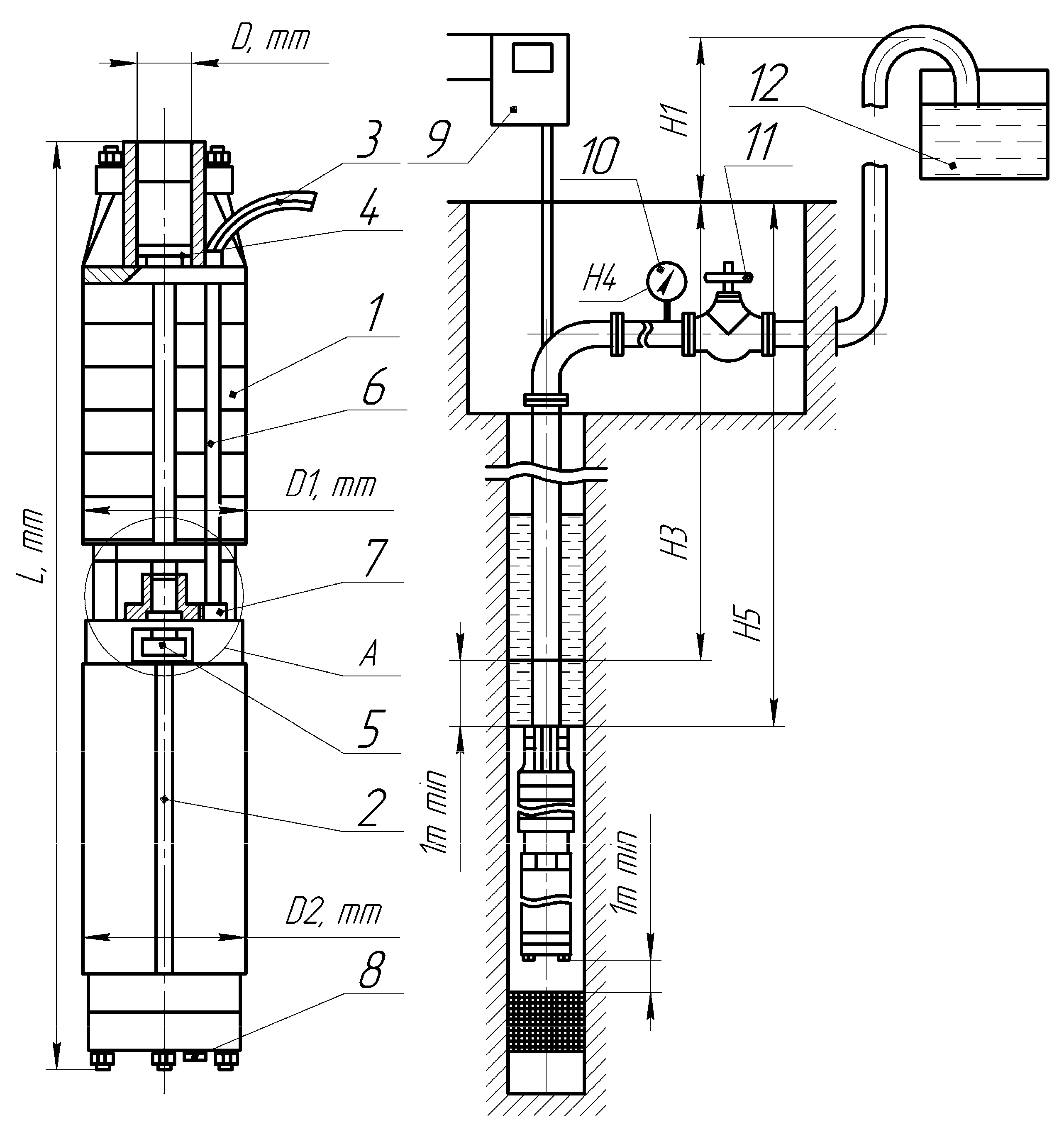
Figure 1. Construction and installation conditions of well pumps: 1—pump part; 2—electric motor; 3—power cable; 4—valve; 5—plate; 6—casing; 7—protective net; 8—drain plug; 9—pump control and protection station; 10—manometer; 11—latch; 12—storage capacity.
Water 15 03609 g001
Figure 2. ECW 10-65-150 pump: 1—electric motor, 2—bearings, 3—stage, 4—impeller, 5—guide vanes, 6—coupling, 7—shaft.
Water 15 03609 g002
Figure 3. Developed pump: 1—shaft, 2—impeller, 3—guide device, 4—automatic balancing device, 5—coupling, 6—mesh.
Water 15 03609 g003
Figure 4. Stages of research implementation.
Water 15 03609 g004
Figure 5. Calculation area, solid-state model of the stage.
Water 15 03609 g005
Figure 6. Qualitative picture of the distribution in the basic pump stage’s flowing part: (a) total pressure; (b) relative velocity.
Water 15 03609 g006
Figure 7. Characteristics of the basic stage of the ECW 10-63-150 pump.
Water 15 03609 g007
Figure 8. Qualitative picture of the distribution in the developed pump stage’s flowing part (model 01): (a) total pressure; (b) relative velocity.
Water 15 03609 g008
Figure 9. Characteristics of the developed stage of the ECW 10-63-150 pump (model 01).
Water 15 03609 g009
Figure 10. Qualitative picture of the distribution in the developed pump stage’s flowing part with vaneless guide vanes (model 02): (a) total pressure; (b) relative velocity.
Water 15 03609 g010
Figure 11. Characteristics of the developed stage of the ECW 10-63-150 pump with vaneless guide vanes (model 02).
Water 15 03609 g011
Figure 12. Qualitative picture of the distribution in the improved pump stage’s flowing part (model 03): (a) total pressure; (b) relative velocity.
Water 15 03609 g012
Figure 13. Characteristics of the improved stage of the ECW 10-63-150 pump (model 03).
Water 15 03609 g013
Figure 14. Qualitative picture of the distribution in the improved pump stage’s flowing part (model 04): (a) total pressure; (b) relative velocity.
Water 15 03609 g014
Figure 15. Characteristics of the improved stage of the ECW 10-63-150 pump (model 04).
Water 15 03609 g015
Table 1. Design features of ECW-type pumps.
Parameters of ECW PumpECW-10-65-150
(⌀260 mm)
ECW 10-63-150 (⌀260 mm)ECW 8-63-110
(⌀205 mm)
ECW 8-65-160
(⌀205 mm)
BerdianskRPE Kharkiv Electro-Mechanical PlantLivny CityAzov-EnergomashBerdiansk CityLivny CityLivny
City
Casing pipe diameter260 mm205 mm
Flow rate, m3/h65636363656565
Head, m22.5150150150110110160
Electric motor, kW27453537453233
Supply voltage, V31.5380380380380380380
Length, mm2000204015202040310019302580
Mass, kg200294198294147173235
Min well flow rate, m³/h130130126130126130130
Nominal current, A93.092.577.092.566.070.0104
Number of stages, pcs8778131313
Table 2. Characteristics of the basic stage of the ECW 10-63-150 pump.
Duty PointFlow Rate Q, m3/hHead, mEfficiency, %
0.053.2518.9710.55
0.106.5019.2819.85
0.2013.019.2833.98
0.4026.019.1451.88
0.6039.018.2664.41
0.8052.016.4072.33
1.0065.014.7574.55
1.2078.011.9770.17
1.4091.08.44058.53
1.601044.30035.65
Table 3. Characteristics of the developed stage of the ECW 10-63-150 pump (model 01).
Duty PointFlow Rate Q, m3/hHead, mEfficiency, %
0.053.5103.218.26
0.2014107.754.87
0.4028106.372.82
0.604275.1364.79
0.805642.9643.14
1.00709.04010.60
Table 4. Characteristics of the developed stage of the ECW 10-63-150 pump with vaneless guide vanes (model 02).
Duty PointFlow Rate Q, m3/hHead, mEfficiency, %
0.053.565.016.36
0.201452.527.30
0.402843.140.00
0.604243.234.07
0.805645.842.38
1.007048.051.77
1.208445.758.65
1.409833.452.69
1.6011233.552.75
1.8012617.047.81
Table 5. Characteristics of the improved stage of the ECW 10-63-150 pump (model 03).
Duty PointFlow Rate Q, m3/hHead, mEfficiency, %
0.053.574.5714.14
0.107.078.3023.84
0.201480.2140.80
0.402880.0858.05
0.604278.7868.51
0.805672.6173.72
1.007061.5475.74
1.208448.8774.46
1.409834.4768.10
1.6011219.3554.16
Table 6. Characteristics of the improved stage of the ECW 10-63-150 pump (model 04).
Duty PointFlow Rate Q, m3/hHead, mEfficiency, %
0.053.576.2215.88
0.107.079.7525.61
0.201482.3041.85
0.402883.8860.46
0.604283.7372.52
0.805676.7977.62
1.007065.0479.42
1.208451.5277.85
1.409836.8372.51
1.6011220.4956.81
Table 7. Comparison of operating parameters of different stages of the developed pump.
ParameterBasic Stage ModelDeveloped Stage Models
01020304
Flow rate, m3/h (max efficiency mode)6528847070
Head, m (max efficiency mode)14.75106.3147.9661.5465.04
Head, m (nominal mode)14.759.0445.6761.5465.04
Efficiency, % (max mode)74.5572.8258.6575.4479.42
Efficiency, % (nominal mode)74.5510.6051.7775.4479.42
Power consumption, W (max efficiency mode)350411,13918,71815,56015,621
Power consumption, W (nominal mode)350417,82415,56015,621
Disclaimer/Publisher’s Note: The statements, opinions and data contained in all publications are solely those of the individual author(s) and contributor(s) and not of MDPI and/or the editor(s). MDPI and/or the editor(s) disclaim responsibility for any injury to people or property resulting from any ideas, methods, instructions or products referred to in the content.