Article

Investigation of Structural Strength and Fatigue Life of Rotor System of a Vertical Axial-Flow Pump under Full Operating Conditions

1
College of Energy and Electrical Engineering, Hohai University, Nanjing 211100, China
2
Shanghai Nuclear Engineering Research & Design Institute, Shanghai 200233, China
3
College of Agricultural Science and Engineering, Hohai University, Nanjing 211100, China
4
College of Water Conservancy and Hydropower Engineering, Hohai University, Nanjing 210098, China
5
College of Science and Technology (MEE Department), University of Rwanda, Kigali 3900, Rwanda
*
Author to whom correspondence should be addressed.
Water 2023, 15(17), 3041; https://doi.org/10.3390/w15173041
Submission received: 27 June 2023 / Revised: 21 August 2023 / Accepted: 22 August 2023 / Published: 24 August 2023
(This article belongs to the Special Issue Advances in Hydrodynamics of Water Pump Station System)

Abstract

:
Axial-flow pumps consider both the conventional pump mode and the pump as turbine (PAT) mode operation and put forward higher requirements for long-term operation stability and structural strength; therefore, it is of great engineering significance to evaluate the structural strength and fatigue life of the rotor under full operating conditions. In this study, based on computational fluid dynamics and the one-way fluid-structure interaction algorithm, the structural strength and fatigue life of the rotor system of a large vertical axial-flow pump under full operating conditions were evaluated and studied. The results show that blade deformation and equivalent stress are generally higher in the PAT mode than in the pump mode. The maximum deformation in both modes occurs at the tip of the blade, while the area of stress concentration is at the root of the blade. Both the deformation and the equivalent stress increase with increasing flow rate. The minimum safety factor occurs at the blade root in both modes, and the safety factor in the PAT mode is relatively smaller than that in pump mode. Therefore, when designing and manufacturing axial flow pumps for turbine duties, priority should be given to material strength at the blade root during PAT mode operation to ensure safe and stable operation. The aim of this study is to provide technical references and theoretical foundations for evaluating the service cycle of axial-flow pumps and the influence on pump life under different operation modes.

1. Introduction

Pumping stations can be used for cross-regional water resource planning to achieve rational distribution of water resources, and they also perform functions such as flood control, drainage, and urban water supply, making it one of the key construction and research projects in various water conservancy projects worldwide [1,2,3,4]. The pumping device is the heart of the pumping station technology and the basic equipment for converting mechanical energy into gravitational potential energy of the liquid [5,6]. Axial-flow pump devices are capable of transporting larger liquid flow rates due to their axial geometric structural characteristics and are a mature and widely used pumping device solution for low-head pumping stations [7,8].
The widespread application of axial-flow pumps in pumping station construction worldwide has led to increasing demands on their long-term stability and reliability, driven by the continuously increasing number and capacity of the systems. However, during operation, axial-flow pump units face potential hazards in the form of vibration and blade cracking caused by water pressure loads, which seriously threaten the safety and stable operation of the units [9]. The rotor system, with the impeller as the main component, is the most vulnerable link to shock loads and one of the main causes of pump failure accidents. Therefore, the structural strength of axial-flow pump impellers has received increasing attention from researchers in related fields in recent years.
The traditional application of experimental methods to study the above problems is undoubtedly associated with high costs [10]. With the advancement of algorithms and computational power, fluid-structure interaction (FSI) technology based on computational fluid dynamics (CFD) and finite element method (FEM) offers a more convenient, faster and less expensive solution for researchers to investigate the structural strength properties of rotating hydraulic machines such as axial-flow pumps that have been investigated in recent years [11,12,13] and that have been able to achieve certain results. Pei et al. [14] applied the FSI method to evaluate and quantitatively analyze the deformation and stress of the blades of an axial-flow pump unit with a bi-directional channel. The results showed that the maximum deformation occurred at the blade rim, and the deformation gradually decreased along the edge from the leading edge (LE) to the trailing edge (TE). Liu et al. [15] analyzed the stress and deformation of the blades of a vertical bi-directional axial-flow pump based on the flow field pressure distribution and found that the stress concentration occurred at the center of the connection between the blade root and the hub and the maximum stress value at stress concentration decreased with increasing flow rate. Shi et al. [16] compared the equivalent stress distributions of an axial-flow pump and a full tubular pump and found that the maximum equivalent stress of an axial-flow pump was lower than that of full tubular pump under different flow conditions. The axial-flow pump also has a smaller stress concentration area compared to the full tubular pump. Under the influence of periodic loading, impeller blades may experience some fatigue. The numerical simulation results from Zhang et al. [17] revealed that the interaction between the rotors and stators of axial-flow pumps is an important factor in the periodic action of the blade, and that the maximum equivalent stress of the blade exhibits periodic oscillations within the rotation cycle with a frequency that coincides with the passing frequency of the blade. The study by Gao et al. [18] showed that the stress distribution of the axial-flow pump impeller was not evenly distributed, but the dynamic stress distribution characteristics were basically similar under different flow conditions. The researchers also found that the dynamic loading on the impeller varied periodically as the impeller rotated. Zhang et al. [19] conducted a comprehensive analysis of the axial-flow pump blade equivalent stress using methods such as fast Fourier transform (FFT) and showed that the stress vibration amplitude of the impeller blade was significantly higher than that of the guide vane. The maximum vibration amplitude of the equivalent stress of the impeller occurred in the center position between LE and TE of the blade hub.
So far, the structure of the rotor system of an axial flow pump in conventional operating mode has been discussed in detail. However, it is important to note that in certain regions of the world with typical monsoon climates, pumping stations are tasked with seasonal water intake [20]. At certain time intervals, pumping stations must divert upstream flooding to downstream areas. To use this water resource more efficiently, pump devices are often designed and operated with their impellers rotating backwards as turbines, referred to as the pump as turbine (PAT) mode [21]. This mode provides a more stable and cleaner power source for the power grid compared to wind and solar energy [22]. Due to their large flow rate, relatively simple structure and easy installation, axial-flow pumps offer good economy [23,24]. In fact, they are even utilized as simple turbine units in certain developing regions and remote districts, and are a popular form of reverse power generation with various types of pumps [25]. Equally important is the investigation of the structural strength of the rotor when operating the axial flow pump in the PAT mode, which has already attracted the interest of some researchers. Meng et al. [26] found that the maximum equivalent stress and total deformation of the impeller blades occurred at 0.75 times the design flow rate in pump mode, while in the PAT mode they occurred at 0.65 times the design flow rate, with the equivalent stress increasing with increasing flow rate. Bai et al. [27] stated that the dynamic stress frequency characteristics were different in the pump mode and the PAT mode. In the pump mode, the primary frequency of the dynamic stress was the rotational frequency of the impeller, with no significant secondary frequencies observed. However, in the PAT mode, blade stress was affected by the combined effects of the adjacent blades, and the primary frequency was a multiple of the rotation frequency, which was highly dependent on the number of blades. Overall, there is still relatively little research on the structural strength and fatigue life of the rotor system of axial-flow pumps operating in both the conventional pump mode and the PAT mode under all operating conditions.
Therefore, this paper utilizes the commercial software interface provided by ANSYS to conduct a study on the rotor system and structural strength of a large vertical axial-flow pump, including the pump mode and the PAT mode, under all operating conditions using the Reynolds-averaged Navier–Stokes (RANS) and one-way FSI methods. In the following sections, Section 2 presents the numerical methods used in the simulation, Section 3 provides the computational settings for the numerical simulation, including the results of the mesh discretization into fluid and solid domain. Section 4 discusses and analyzes the results of the simulation, while the specific main conclusions are presented in Section 5.

2. Methodology

2.1. Fluid Governing Equations

The internal flow of an axial-flow pump is a complex turbulent flow with fluid viscosity, and the compressibility of the fluid is generally neglected [28]. In this study, the RANS algorithm was used to model the turbulence internal the pump device; thus, the continuity equation can be expressed as
u ¯ j x j = 0 ,
and the momentum conservation equation is written as
ρ u ¯ i t + x j ρ u ¯ i u ¯ j = p ¯ x i + x j μ u ¯ i x j ρ u i u j ¯ + f i ,
where the overline symbol ( ¯ ) represents the time-averaged operation, u i and u j stand for the velocity components in x, y and z directions, the sub-scripts are the directional indices. t is the physical time, ρ is the fluid density and μ is the dynamic viscosity of the fluid. Additionally, f denotes the external force. The two-way Re-Normalization Group (RNG) k ϵ turbulence model is used to close the governing equations [29,30,31,32]. The transport equations of turbulence kinetic energy k and turbulence dissipation rate ϵ are calculated, respectively, as
( ρ k ) t + x j ρ k u i = x j μ + μ t σ k k x j + P k ρ ε ,
( ρ ε ) t + x j ρ ε u j = x j μ + μ t σ ε ε x j + ε k C ε 1 RNG P k C ε 2 ε ,
where ν t stands for the turbulent viscosity and P k is the turbulence production rate due to viscous forces. C ϵ 1 RNG , C ϵ 2 , σ k and σ ϵ are all the constants of the RNG model.

2.2. Structural Governing Equations

Considering the significant difference in magnitude between the expected deformation of the axial-flow pump and the scale of the flow field, the influence of the deformation on the flow field can be essentially neglected [33,34]. Therefore, in this study, a one-way FSI method was adopted for investigation. The governing equation of blade structure dynamics is expressed as
M q ¨ t ( t ) + C q ˙ t ( t ) + K q t ( t ) = Q ( t ) .
Here, M , C and K refer to the matrix of structure mass, structural damping, and structural rigidity, respectively. q ¨ , q ˙ and q denote the nodal acceleration vector, the velocity vector, and the displacement vector, and Q represents the fluid load vector. The solution flow chart of one-way FSI adopted in this paper is shown in Figure 1.

3. Numerical Settings

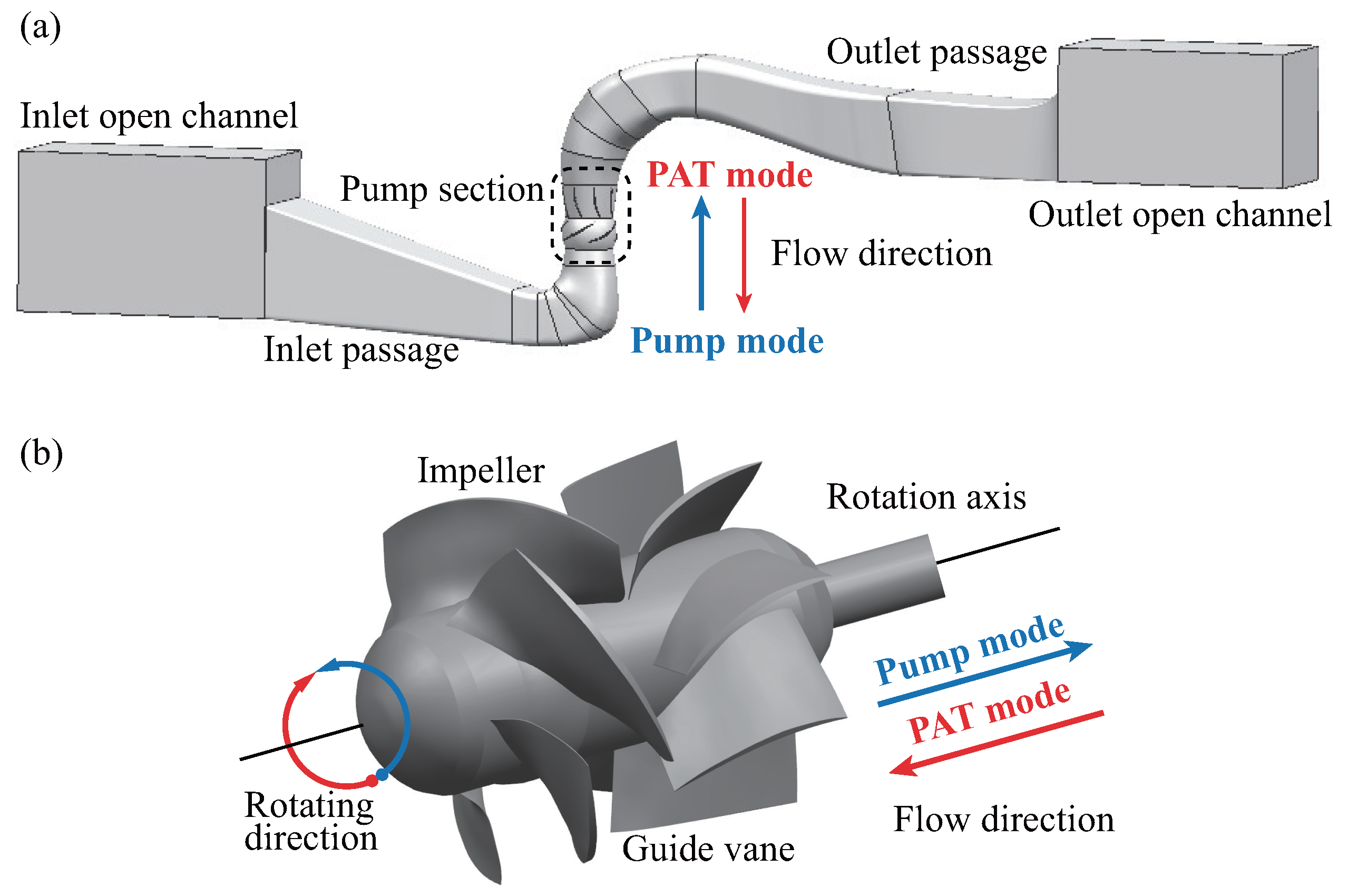
3.1. Geometry of Pump Device

This paper conducts numerical simulation and theoretical research on a large vertical axial-flow pump in a certain pumping station. Figure 2 shows the schematic diagram of the pump device, the entire pump device consists of an open inlet channel, an elbow-shaped inlet passage, a pump section, a low hump-shaped outlet passage, and an open outlet channel. The pump section includes an impeller part composed of five blades and a guide vane part composed of eight blades. The basic parameters of the pump section are listed in Table 1.
The axial-flow pump device has two different modes. One is the conventional pump mode that uses the rotation of the impeller to transport water. The other mode utilizes the elevation difference of the water flow to make the pump impeller rotate in the opposite direction and drive the generator to generate electricity. This mode is usually called the reverse power generation mode of the pump or the PAT mode. Both modes are also indicated in Figure 2. In addition, the axial-flow pump blades are made of ZG 0 Cr13Ni 4 CuMo stainless steel, with a yield strength of 668 MPa, an ultimate strength of 800 MPa and a fatigue limit of 210 MPa.

3.2. Fluid Field

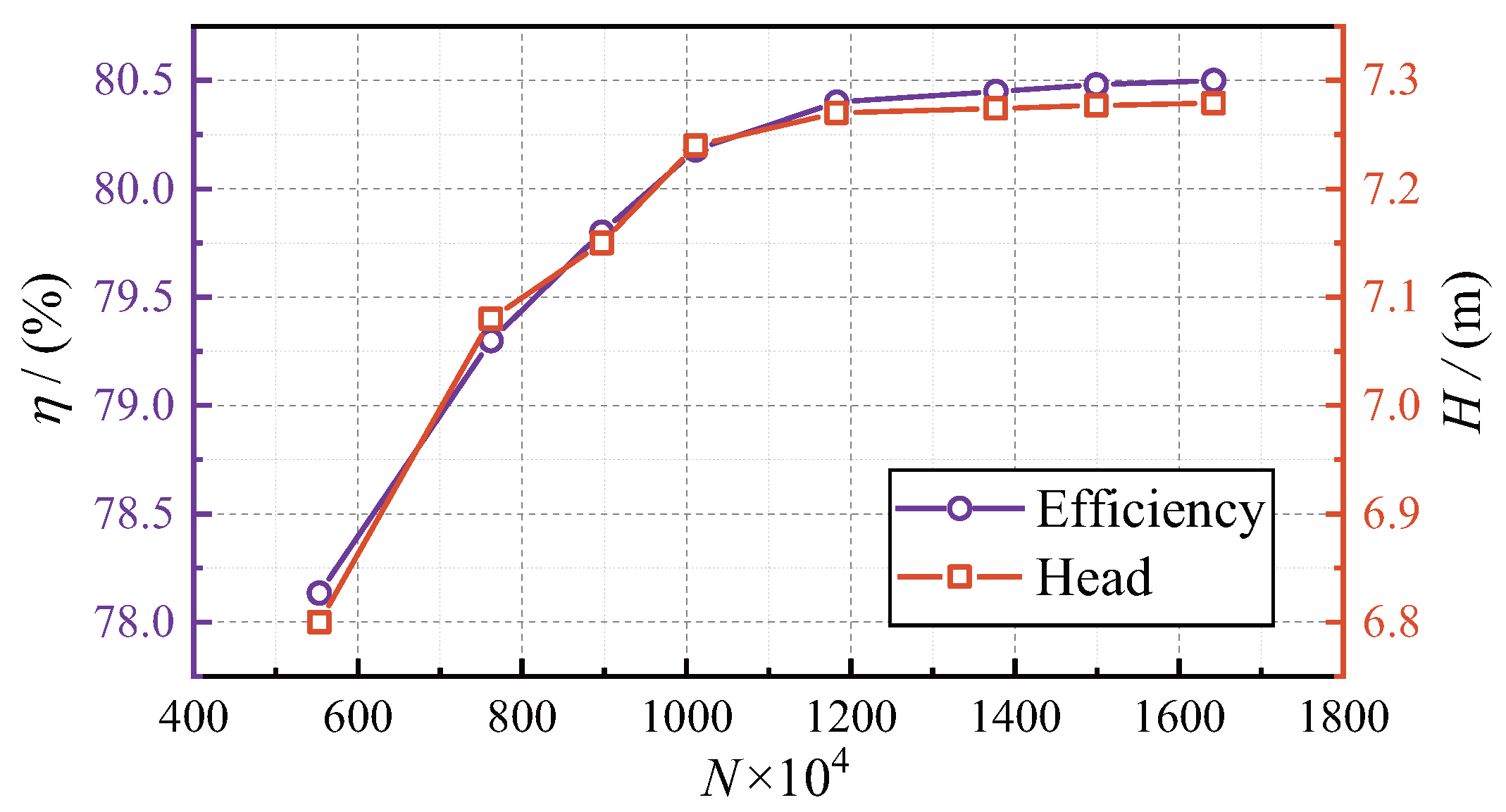
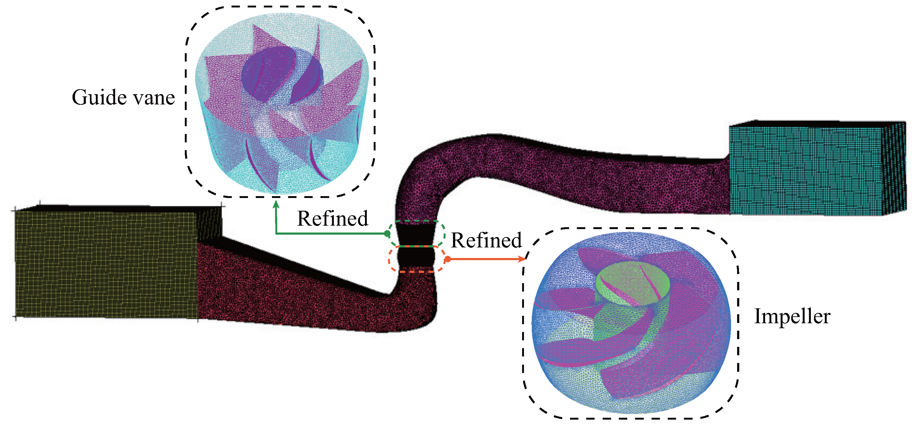
3.2.1. Spatial Discretization

In this study, ANSYS ICEM was used to discretize the fluid domain of the entire axial-flow pump device. The discretization was carried out using unstructured grids, while structured grids were used to discretize the inlet and outlet channels. In order to ensure accurate flow solutions, local refinements of the grid were performed in critical areas such as the impeller and guide vanes, where complex flows exist. Initially, eight grid configuration schemes were established, and the head and efficiency of the axial flow pump under each scheme were computed. Figure 3 shows the verification curve of grid independence of the fluid domain. Both efficiency and head increase with the increase in the number of grids, indicating gradual convergence. When the number of grids exceeds 11.83 million, the degree of change in head and efficiency with the number of grids becomes very small.
Therefore, after considering the comprehensive factors of efficiency and computational accuracy, the final total number of grids was determined to be 11.83 million grid cells, of which the inlet passage accounted for 3.4 million, the impeller part accounted for 2.83 million, the guide vane part accounted for 2.8 million, and the outlet passage part accounted for 2.8 million. The grid quality reached 0.32, which met the requirements for accurate simulation. A schematic diagram of the meshing result of the pump device is shown in Figure 4.

3.2.2. Solution Method and Boundary Conditions

The steady-state flow fields of an axial-flow pump were simulated under six different operating conditions, including low flow rate ( Q = 0.8 Q BEP ), optimal flow rate ( Q = 1.0 Q BEP ), and high flow rate ( Q = 1.2 Q BEP ), in both the pump mode and the PAT mode. Here, Q BEP refers to the respective optimal operating point flow rate of the two modes. The optimal guide vane angle was selected for each operating condition. The numerical simulations of the flow fields were conducted using the FLUENT 19.2 commercial software. The RNG k ϵ turbulence model was selected, and the SIMPLEC algorithm was used to couple the velocity and pressure fields. A first-order implicit scheme was used for time discretization, while a second-order upwind scheme was used for the convective terms of the momentum equation and other spatial terms. The rotating and stationary regions were connected through interfaces. The inlet boundary condition was set as a mass flow inlet, while the outlet boundary condition was set as a pressure outlet and the solid wall was set as a no-slip wall. The number of iterations was designated as 3000.

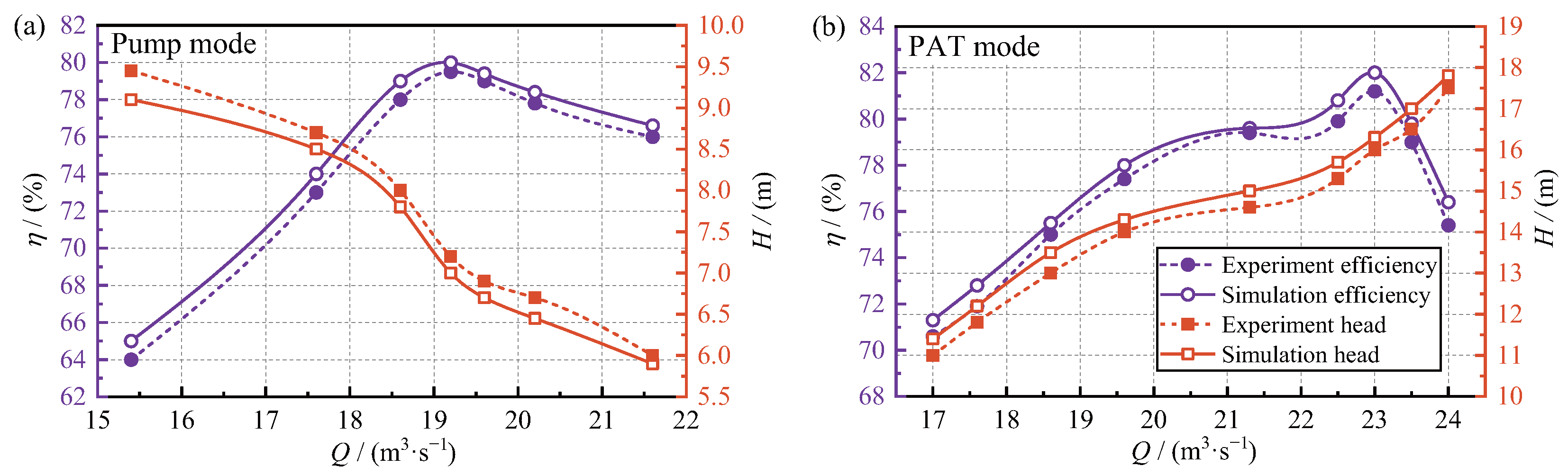
3.2.3. Validation of External Characteristics

To verify the reliability of the numerical simulation results, model tests were conducted for the pump mode and the PAT mode of the axial-flow pump at a rated speed in this study. The experiments were carried out on the hydraulic machinery multi-functional model test bench of Hohai University [35], as shown in Figure 5. The total uncertainty of the experiment was less than 0.4%. The diameter of the model pump impeller was D = 300 mm, and the experimental rotation speed was 1305.8 r/min. The experimental results were converted to the values of the prototype axial-flow pump according to the similarity law and compared with the simulated efficiency and head. The comparison results are shown in Figure 6. The trend of efficiency and head with flow rate in a numerical simulation is consistent with the experimental results, but the numerical simulation overestimates the efficiency and head slightly. This is partly due to the large roughness and leakage losses of the model pump in the experiment. The maximum error at each flow rate condition did not exceed 3%; thus, the numerical calculation results can be considered acceptable.

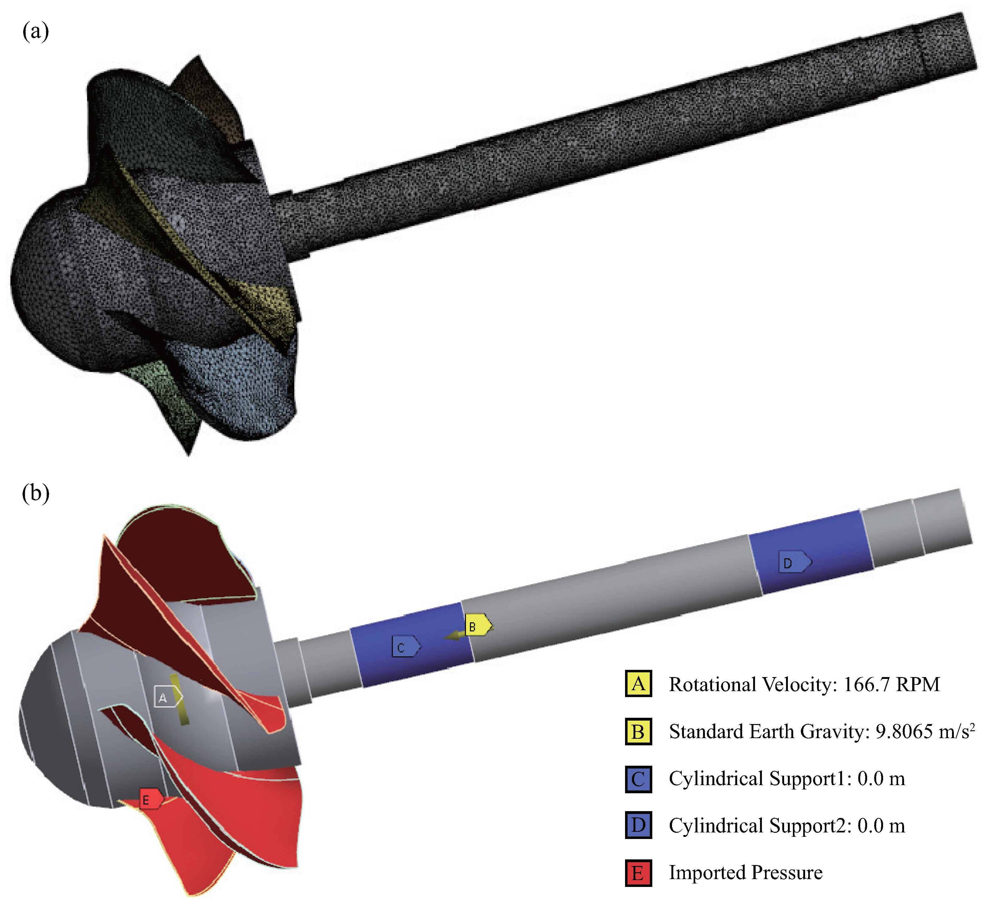
3.3. Structural Field

In this study, the Mesh module interface provided by the ANSYS Workbench platform was used to perform mesh generation on the solid domain of the blade [36]. To ensure the accuracy and reliability of the mesh generation, four mesh generation schemes were established, and the independence of the solid field mesh was verified. The blade region was divided into four different sizes of 45 mm, 35 mm, 25 mm, and 15 mm, respectively, and local refinement was performed on the blade. The grid division schemes and the maximum stress and maximum displacement values under each scheme are shown in Table 2.
Among the four schemes, as the grid size of the blade region decreased and the number of elements and nodes increased, both the maximum stress value and the maximum displacement value showed a monotonic increase. Therefore, Scheme IV was selected as the mesh scheme for subsequent computations. In this scheme, the number of elements reached 322,237, the number of nodes reached 557,320, and the final details of the mesh can be found in Figure 7a.
When performing a one-way FSI computation on the axial-flow pump device, it is necessary to add constraint conditions in various directions of the blade. Figure 7b shows the constraint conditions added to the blades, where A represents the gravity constraint (Standard Earth Gravity), and the acceleration due to gravity is set to 9.8066 m/s 2 . B represents the circumferential velocity (Rotational Velocity), and the rotating centrifugal force acts on the structural part of the blade during rotation. The rotational speed of the impeller is set to 166.7 r/min. C and D represent cylindrical constraints (Cylindrical Support), which prevent displacement of the rotating part of the impeller. E represents the pressure-bearing surface (Imported Pressure), where the water pressure on the surface of the blade computed from the steady-state flow field is imported to this pressure-bearing surface.

4. Results and Discussion

4.1. Analysis of Deformation and Stress of Blades

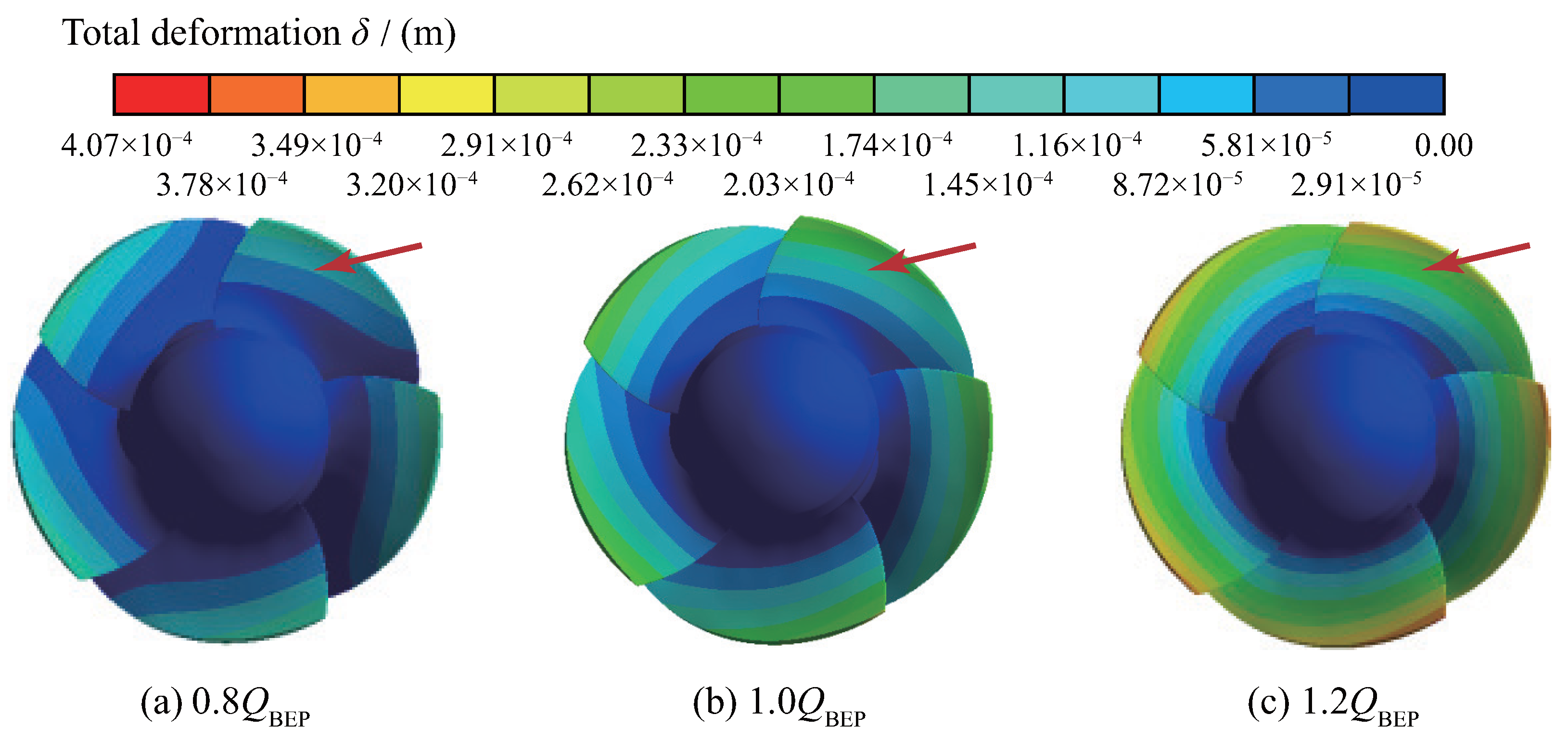
4.1.1. Total Deformation of Blades

Figure 8 shows the solid total deformation of the blade of the axial-flow pump device operating in pump mode at 0.8 Q BEP , 1.0 Q BEP , and 1.2 Q BEP flow rates. The maximum deformation of the blade is δ = 0.158 mm at 0.8 Q BEP , δ = 0.245 mm at 1.0 Q BEP , and δ = 0.407 mm at 1.2 Q BEP . As the flow rate increases, the maximum deformation on the blade surface gradually increases. The main deformation distribution of the blade is increasing gradually from the hub along the wheel rim, while there is almost no deformation at the hub. The deformation gradient near the hub is relatively small, and the increase in radial deformation is slow. The maximum deformation occurs at the water-inlet edge of the blade pressure surface (PS), and the deformation gradually decreases along the circumferential direction towards the water-outlet edge. This is because the thickness of the blade is the thinnest at the water-inlet edge and the thickest at the hub.
The distribution of solid total deformation of the blades of the axial-flow pump device operating in the PAT mode at 0.8 Q BEP , 1.0 Q BEP , and 1.2 Q BEP flow rates is shown in Figure 9. At 0.8 Q BEP , the maximum deformation of the blade is δ = 0.167 mm, at 1.0 Q BEP it is δ = 0.256 mm, and at 1.2 Q BEP it is δ = 0.410 mm. The total deformation of the blade increases with the flow rate, and the area of deformation of the blade gradually increases. The maximum deformation values of the PS and suction surface (SS) can be found at the top wheel rim of the blade, and the thinner top of the blade is more susceptible to deformation due to the impact of the water flow, which can have a certain impact on the safe use of the blade. Similar to the pump mode, the deformation at the thicker hub can be ignored. In the PAT mode, the deformation of the blade is slightly increased compared to the pump mode. This is because during reverse power generation, the flow state is more turbulent, and the fluid does more work on the blade, which intensifies the deformation of the blade and thus has a certain impact on the safety and stability of the pump device.

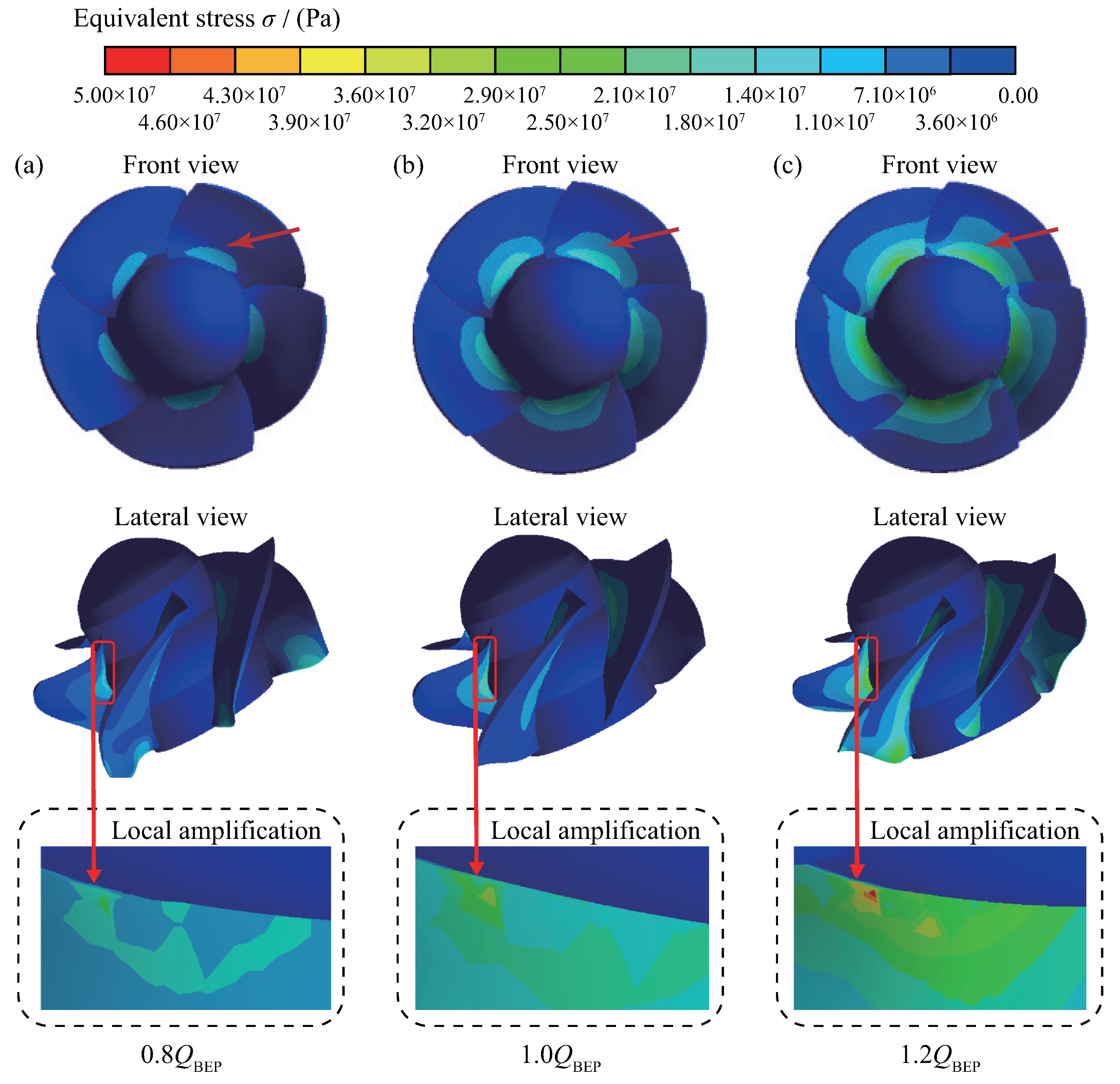
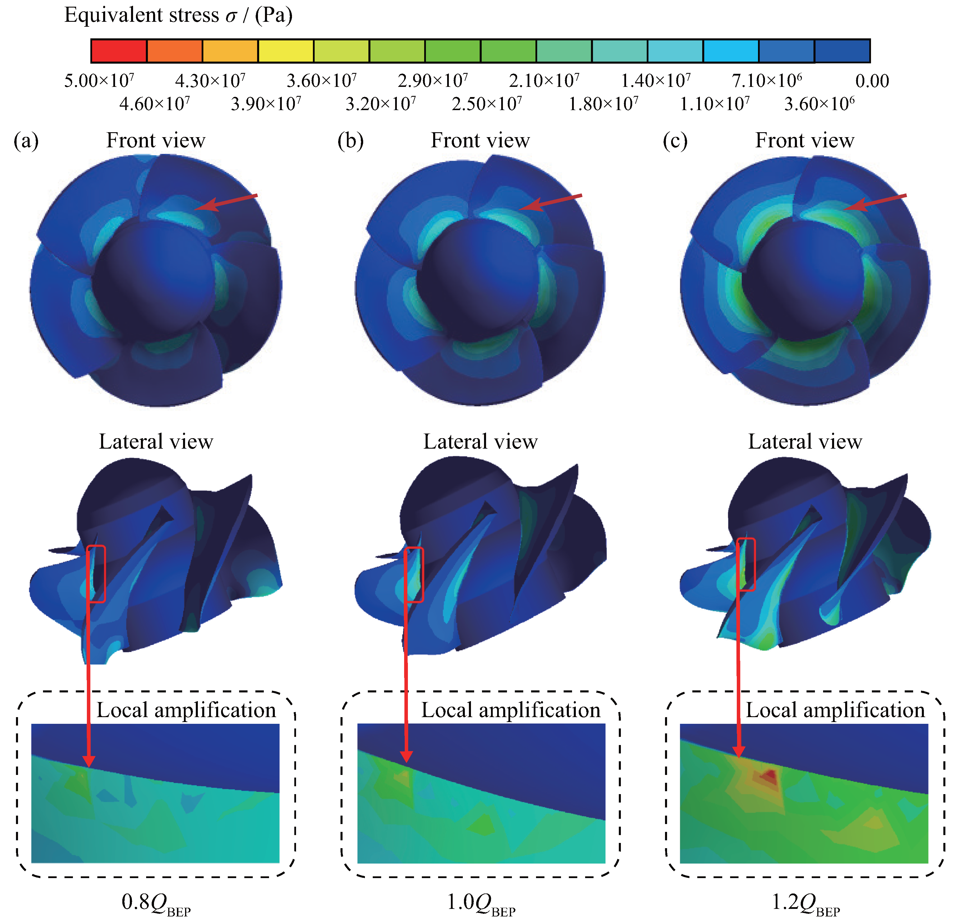
4.1.2. Equivalent Stress of Blades

In this study, the equivalent stress σ of the rotor system is calculated according to the fourth strength theory, and the calculation equation is
σ = 1 2 σ 1 σ 2 2 + σ 1 σ 3 2 + σ 3 σ 2 2 ,
where σ 1 , σ 2 and σ 3 are principle stresses. The distribution of the equivalent stress of the blade of the axial-flow pump device operating in the pump mode and the PAT mode at the above-mentioned three different flow rates is shown in Figure 10 and Figure 11. Stress concentration occurs at the root of the blade in both modes, which may cause fatigue cracks and static load fracture in the blade. The maximum equivalent stress is at the root of the blade on the SS, and the stress on the blade decreases gradually from the root near the hub to the rim, which is caused by the shape of the blade. It can be observed that the back of the blade is more prone to flow separation near the position close to the hub, leading to a significant difference in equivalent stress between the front and back of the blade.
When operating in the pump mode, the equivalent stress of the blade increases with the increase in the flow rate. At 0.8 Q BEP , the maximum equivalent stress is 20.34 MPa, while at 1.0 Q BEP it reaches 31.13 MPa, and at 1.2 Q BEP it reaches up to 47.95 MPa. The corresponding trend between flow rate and equivalent stress in the PAT mode is consistent with that in the pump mode. At 0.8 Q BEP , the maximum stress value of the blade is 22.23 MPa, while at 1.0 Q BEP , it reaches 33.12 MPa, and at 1.2 Q BEP , it reaches up to 49.93 MPa. The maximum equivalent stress in the PAT mode is higher than that in the pump mode, and the high-stress distribution area is larger at 0.8 Q BEP .

4.2. Analysis of Fatigue Life of Impeller

According to the fatigue loss theory, the fatigue strength is checked by calculating the safety factor n σ , and its theoretical calculation equation is
n σ = σ 1 K σ D σ a [ n ] .
Here, σ 1 is the fatigue limit, K σ D is the fatigue reduction coefficient which equals 2.2 and σ a is the stress amplitude. Using the maximum stress value for checking, the corresponding safety allowance coefficient [ n ] is 1.5. In this study, the Fatigue Tools module in ANSYS Workbench is called to evaluate the fatigue life of axial flow pump. The Goodman model is used to modify the average value of alternating stress.

4.2.1. Number of Stress Cycles

The minimum blade cycle times in all operating conditions for both modes exceeded 10 6 cycles, indicating that the blade usage time and usage cycles are close to infinite cycling. This proves that when operating in the pump mode and the PAT mode, the blade usage time and usage cycles of the axial-flow pump device are within the safe allowable range, meeting the safety requirements of the material and ensuring structural strength for long-term safe and stable operation.

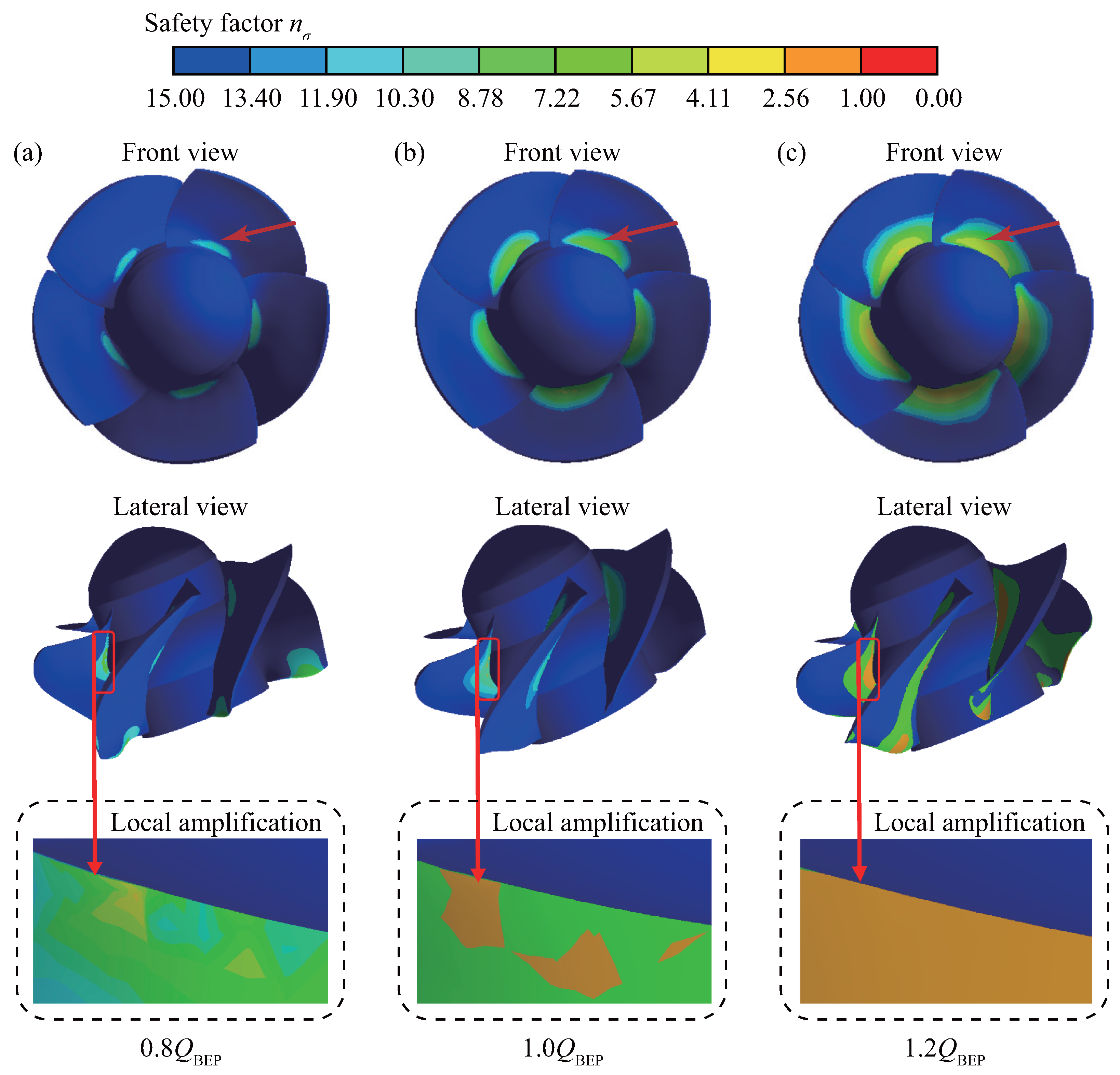
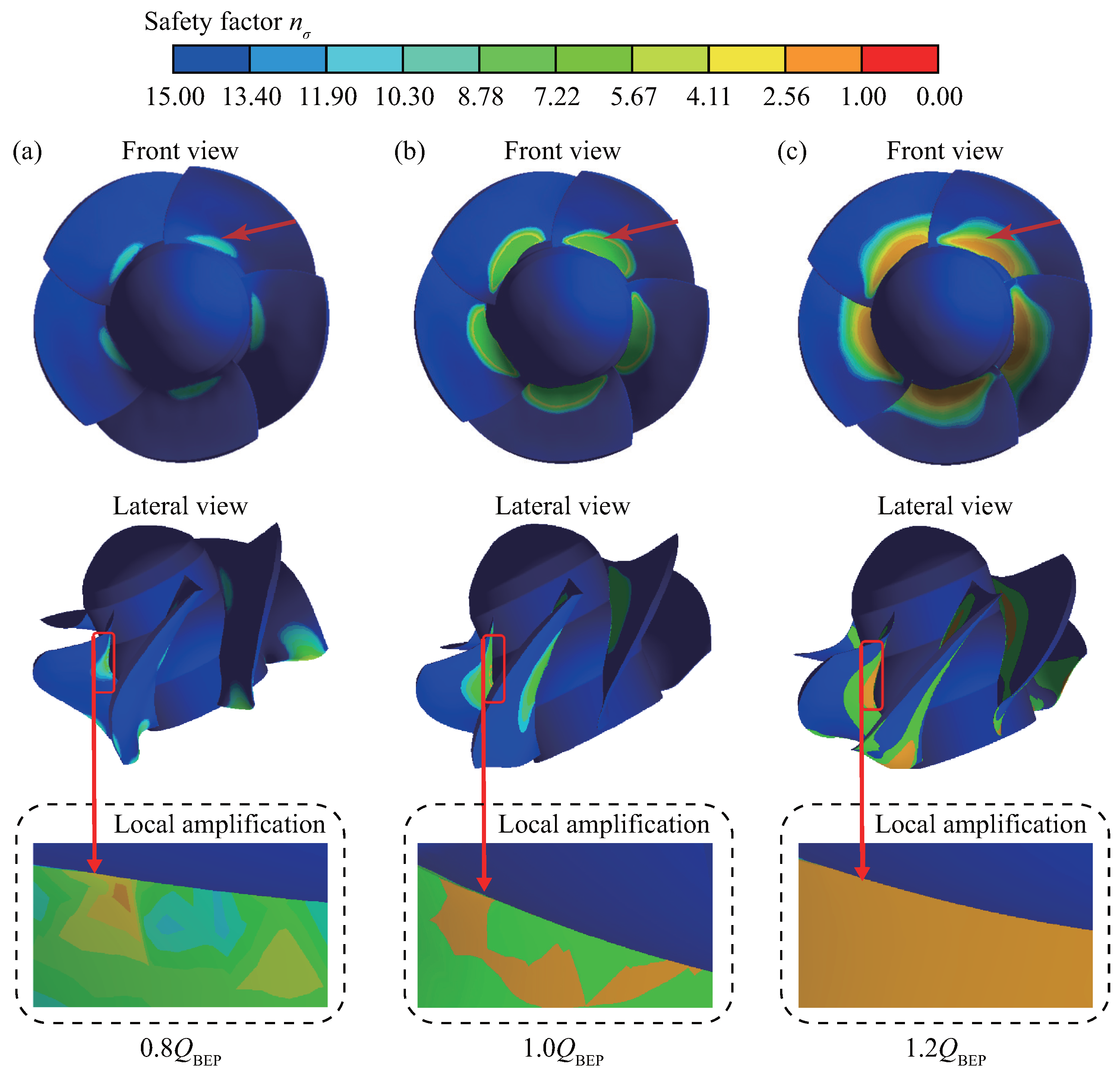
4.2.2. Blade Safety Factor

Figure 12 depicts the distribution of blade safety factors of the axial-flow pump device in the pump mode at 0.8 Q BEP , 1.0 Q BEP , and 1.2 Q BEP flow rates. In all operating conditions, the region where the minimum safety factor of the blade is located is at the connection between the blade root and the hub, while the safety factor is significantly higher at the blade tip. The amplified area in the figure shows the region where the minimum safety factor is located, and the distribution characteristics under each operating condition exhibit a noticeable regular pattern. The minimum safety factor at 0.8 Q BEP is n σ = 4.24 , at 1.0 Q BEP it is n σ = 2.77 , and at 1.2 Q BEP it is n σ = 1.79 . As the flow rate increases, the safety factor of the blade root decreases, making it more susceptible to damage, which is consistent with the pattern observed at the maximum equivalent stress of the blade. Additionally, Figure 13 compares the blade safety factors of the impeller obtained from numerical simulation and theoretical analysis for the axial-flow pump device operating in the pump mode at the three different flow rates mentioned above, and the relative error is provided. The relative error between the simulated minimum safety factor and the theoretical value increases with the flow rate. At a 0.8 Q BEP flow rate, the relative error of the minimum safety factor is 2.17%, while it is 3.75% at 1.0 Q BEP . The maximum error is 6.55% at a 1.2 Q BEP flow rate because as the flow rate increases, the relative error in the solution denominator decreases due to the decrease in the safety factor. The absolute error is within the acceptable range, which verifies the accuracy and reliability of the numerical simulation results for the safety factor.
Figure 14 presents the distribution of blade safety factors for the axial-flow pump device operating in the PAT mode at 0.8 Q BEP , 1.0 Q BEP , and 1.2 Q BEP flow rates. Similar to the operation in the pump mode, the minimum safety factor of the blade mainly concentrates at the blade root where it connects to the hub, while the safety factor at the blade edge is relatively larger for different flow rates. The figure also has local amplification on the region where a small safety factor distribution exists. At a 0.8 Q BEP flow rate, the minimum safety factor is n σ = 3.86 , while it is n σ = 2.60 at 1.0 Q BEP , and n σ = 1.73 at 1.2 Q BEP . As the flow rate increases, the safety factor of the blade root decreases, which corresponds to the pattern observed at the maximum equivalent stress of the blade. Figure 15 compares the blade safety factors obtained from numerical simulation and theoretical analysis for the axial-flow pump device operating in the PAT mode at the three different flow rates. The trend of the minimum safety factor error is similar to that under the pump mode. The relative error between the simulated and theoretical values increases with the flow rate. At a 0.8 Q BEP flow rate, the relative error of the minimum safety factor is 4.61%, while it is 7.44% at 1.0 Q BEP and 8.81% at 1.2 Q BEP . It can be observed that the error between the simulated and theoretical values under the PAT mode is generally higher than that under the pump mode, which can be attributed to the more complex internal flow field under the PAT mode. Considering that the value of the safety factor is small, it leads to a small denominator and a large relative error when solving the relative error. However, the maximum error is still less than 10% under all operating conditions, so the simulation results can be considered accurate.
In summary, for the axial-flow pump device operating in both pump and PAT modes, the minimum safety factor of the blade is mainly concentrated at the blade root. Therefore, the blade root needs to be reinforced during the manufacturing process to ensure the material safety during operation. Compared with the operation under the pump mode, the minimum safety factor of the blade under the PAT mode is smaller at a low flow rate of 0.8 Q BEP and an optimal flow rate of 1.0 Q BEP . This may be attributed to the more turbulent and poorer flow state of the water flow during the PAT mode, which results in more work performed by the water flow on the blade and greater impact on the blade. Under these conditions, the blade is more susceptible to damage. Therefore, the material strength and safety stability of the blade under PAT mode should be given special consideration during the design and manufacturing process.

5. Conclusions

In this paper, commercial software ANSYS and the one-way FSI algorithm are used to study the equivalent stress, blade deformation, and fatigue life characteristics of the rotor system of a large vertical axial-flow pump operating in both pump and PAT modes at their respective three different flow rates: 0.8 Q BEP , 1.0 Q BEP , and 1.2 Q BEP . The main conclusions of this study are summarized as follows:
(1)
When the axial-flow pump device operates in both pump mode and PAT mode, the maximum blade deformation increases with the increasing flow rate. The deformation at the blade root can be neglected and the radial deflection gradient is small, while the deflection gradient increases gradually near the top of the blade. In comparison, the maximum deformation in the PAT mode is generally higher than that in the pump mode at all flow rates.
(2)
Under all operating conditions, the stress concentration phenomenon mainly occurs at the blade root, with the maximum equivalent stress at the impeller root occurring at the blade suction surface, and the stress gradually decreasing from the blade root to the blade edge. Comparing different flow rate conditions, the maximum equivalent stress of both modes occurs at a flow rate of 1.2 Q BEP . Under the same flow rate conditions, the equivalent stress in the PAT mode is relatively higher than in the pump mode.
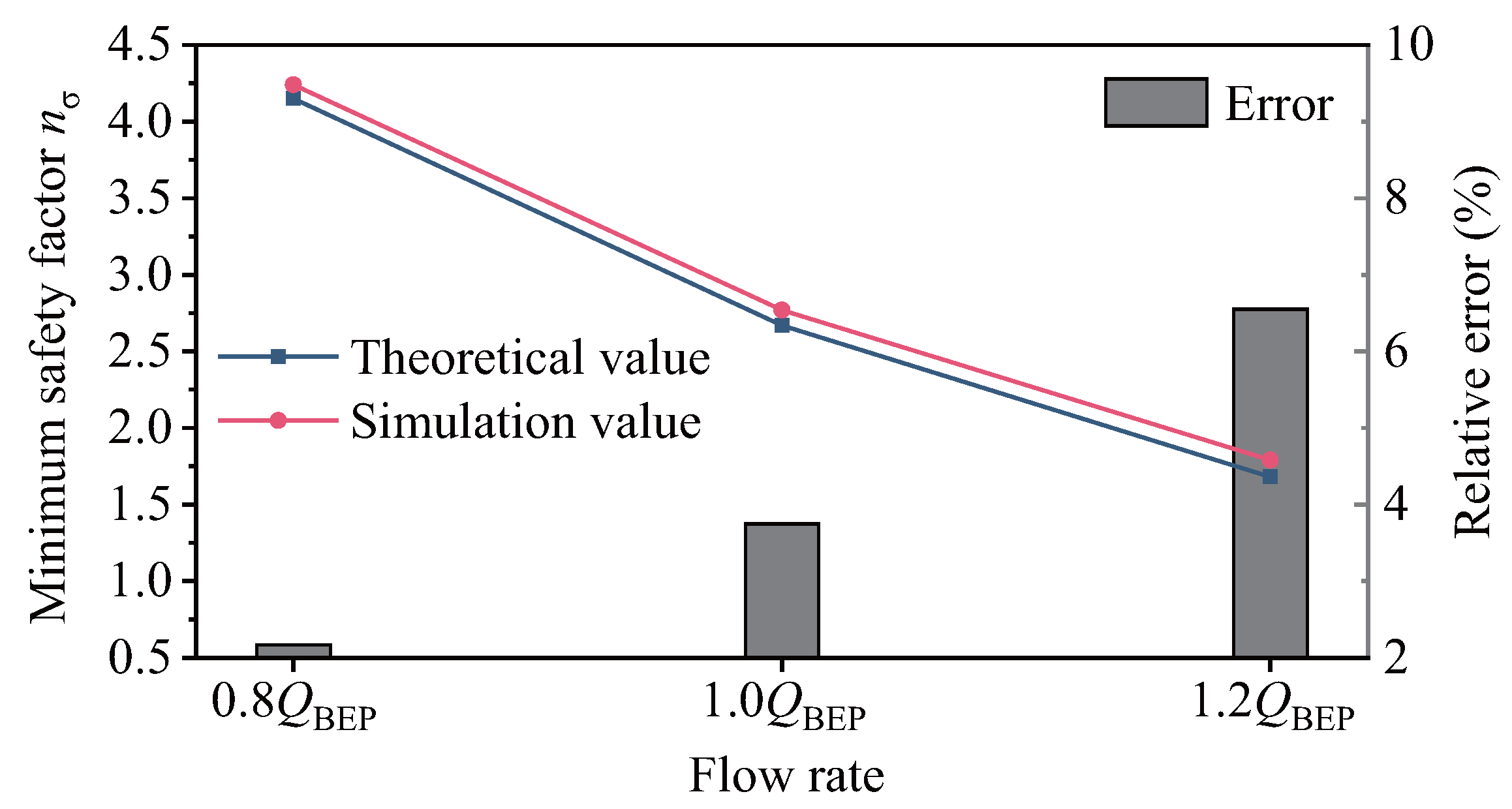
(3)
The number of cycles of the impeller exceeds 10 6 under all operating conditions, indicating that the load carrying capacity of the impeller is within the safe allowable range when the axial-flow pump device operates in both modes. The simulated impeller safety factor in the pump mode and the pump-turbine mode is slightly higher than the theoretical calculation value, which is reasonable. The minimum safety factor appears at the blade root, and the safety factor is smaller when operating in the PAT mode. Therefore, the blade root of the blade needs to be strengthened during processing to ensure the safe and stable operation of the pump device.
The above conclusions can be used to evaluate the service cycle of axial-flow pumps and the influence on pump life under different operation modes. At present, we only analyze the influence of water pressure on the structural strength of the rotor system under ideal conditions. In practical engineering, the impeller may have cracks in the long-term operation process. Therefore, in future work, more research will be conducted on the influence of cracks on the life of the axial-flow pump under full operating conditions and the comprehensive evaluation of the PAT generation economy and the influence on the life of the pump.

Author Contributions

Conceptualization, K.K.; methodology, K.K. and Z.C.; software, H.L. and Z.C.; validation, H.L., Z.C. and K.K.; formal analysis, H.L. and Z.C.; investigation, H.L. and Z.C.; resources, K.K. and H.C.; data curation, H.L. and Z.C.; writing—original draft preparation, H.L., Z.C.; writing—review and editing, K.K., H.C. and M.B.; visualization, H.L. and Z.C.; supervision, Y.Z., J.F. and H.X.; project administration, Y.Z., J.F. and H.X.; funding acquisition, K.K. and H.L. All authors have read and agreed to the published version of the manuscript.

Funding

This research was funded by the National Natural Science Foundation of China (52379086; 52009033), the Natural Science Foundation of Jiangsu Province (BK20200509), the Postdoctoral Research Foundation of China (2022T150185; 2022M711021), and the Project on Excellent Post-graduate Dissertation of Hohai University (422003515).

Data Availability Statement

Not applicable.

Conflicts of Interest

The authors declare no conflict of interest.

Abbreviations

CFDComputational fluid dynamics
FEMFinite element method
FSIFluid–structure interaction
FFTFast Fourier transform
PATPump as turbine
RNGRe-normalization group
RANSReynolds-averaged Navier–Stokes
BEPBest efficiency point
PSPressure surface
SSSuction surface
LELeading edge
TETrailing edge
u i and u j Velocity components in x, y and z direction
i and jDirectional indices for x, y and z
tPhysical time
ρ Fluid density
μ Fluid dynamic viscosity
f i External force
kTurbulence kinetic energy
ϵ Turbulence dissipation rate
C ϵ 1 RNG , C ϵ 2 , σ k and σ ϵ Constants of the RNG model
M Matrix of structure mass
C Matrix of structural damping
K Matrix of structural rigidity
q ¨ Nodal acceleration vector
q ˙ Nodal velocity vector
q Nodal displacement vector
Q Fluid load vector
η Efficiency
HHead
DImpeller diameter
QFlow rate
Q r Rated flow rate
nRotation speed
n r Rated rotation speed
δ Deformation
σ Equivalent stress
σ 1 , σ 2 and σ 3 Principle stresses
n σ Safety factor
σ 1 Fatigue limit
K σ D Fatigue reduction coefficient
σ a Stress amplitude
[ n ] Safety allowance coefficient

References

  1. Feng, J.; Luo, X.; Guo, P.; Wu, G. Influence of tip clearance on pressure fluctuations in an axial flow pump. J. Mech. Sci. Technol. 2016, 30, 1603–1610. [Google Scholar] [CrossRef]
  2. Shi, L.; Zhang, W.; Jiao, H.; Tang, F.; Wang, L.; Sun, D.; Shi, W. Numerical simulation and experimental study on the comparison of the hydraulic characteristics of an axial-flow pump and a full tubular pump. Renew. Energy 2020, 153, 1455–1464. [Google Scholar] [CrossRef]
  3. Zhang, X.; Tang, F.; Chen, Y.; Huang, C.; Chen, Y.; Wang, L.; Shi, L. Experimental study on the internal pressure pulsation characteristics of a bidirectional axial flow pump operating in forward and reverse directions. Machines 2022, 10, 167. [Google Scholar] [CrossRef]
  4. Abera, F.F.; Asfaw, D.H.; Engida, A.N.; Melesse, A.M. Optimal Operation of Hydropower Reservoirs under Climate Change: The Case of Tekeze Reservoir, Eastern Nile. Water 2018, 10, 273. [Google Scholar] [CrossRef]
  5. Xi, S.; Desheng, Z.; Bin, X.; Weidong, S.; van Esch, B.B. Experimental and numerical investigation on the effect of tip leakage vortex induced cavitating flow on pressure fluctuation in an axial flow pump. Renew. Energy 2021, 163, 1195–1209. [Google Scholar] [CrossRef]
  6. Kan, K.; Yang, Z.; Lyu, P.; Zheng, Y.; Shen, L. Numerical study of turbulent flow past a rotating axial-flow pump based on a level-set immersed boundary method. Renew. Energy 2021, 168, 960–971. [Google Scholar] [CrossRef]
  7. Shen, S.; Qian, Z.; Ji, B.; Agarwal, R.K. Numerical investigation of tip flow dynamics and main flow characteristics with varying tip clearance widths for an axial-flow pump. Proc. Inst. Mech. Eng. Part A J. Power Energy 2019, 233, 476–488. [Google Scholar] [CrossRef]
  8. Wang, C.; Wang, F.; Tang, Y.; Zi, D.; Xie, L.; He, C.; Zhu, Q.; Huang, C. Investigation into the phenomenon of flow deviation in the S-shaped discharge passage of a slanted axial-flow pumping system. J. Fluids Eng. 2020, 142, 041205. [Google Scholar] [CrossRef]
  9. Zhang, D.S.; Shi, W.D.; Bin, C.; Guan, X.F. Unsteady flow analysis and experimental investigation of axial-flow pump. J. Hydrodyn. Ser. B 2010, 22, 35–43. [Google Scholar] [CrossRef]
  10. Zhang, D.; Shi, W.; Van Esch, B.B.; Shi, L.; Dubuisson, M. Numerical and experimental investigation of tip leakage vortex trajectory and dynamics in an axial flow pump. Comput. Fluids 2015, 112, 61–71. [Google Scholar] [CrossRef]
  11. Keck, H.; Sick, M. Thirty years of numerical flow simulation in hydraulic turbomachines. Acta Mech. 2008, 201, 211–229. [Google Scholar] [CrossRef]
  12. Hübner, B.; Weber, W.; Seidel, U. The role of fluid-structure interaction for safety and life time prediction in hydraulic machinery. In Proceedings of the IOP Conference Series: Earth and Environmental Science; IOP Publishing: Bristol, UK, 2016; Volume 49, p. 072007. [Google Scholar]
  13. Trivedi, C.; Cervantes, M.J. Fluid-structure interactions in Francis turbines: A perspective review. Renew. Sustain. Energy Rev. 2017, 68, 87–101. [Google Scholar] [CrossRef]
  14. Pei, J.; Meng, F.; Li, Y.; Yuan, S.; Chen, J. Fluid–structure coupling analysis of deformation and stress in impeller of an axial-flow pump with two-way passage. Adv. Mech. Eng. 2016, 8, 1687814016646266. [Google Scholar] [CrossRef]
  15. Liu, X.; Xu, F.; Cheng, L.; Pan, W.; Jiao, W. Stress Characteristics Analysis of Vertical Bi-Directional Flow Channel Axial Pump Blades Based on Fluid–Structure Coupling. Machines 2022, 10, 368. [Google Scholar] [CrossRef]
  16. Shi, L.; Zhu, J.; Wang, L.; Chu, S.; Tang, F.; Jin, Y. Comparative Analysis of Strength and Modal Characteristics of a Full Tubular Pump and an Axial Flow Pump Impellers Based on Fluid-Structure Interaction. Energies 2021, 14, 6395. [Google Scholar] [CrossRef]
  17. Zhang, D.; Pan, D.; Xu, Y.; Shao, P.; Wang, G. Numerical investigation of blade dynamic characteristics in an axial flow pump. Therm. Sci. 2013, 17, 1511–1514. [Google Scholar] [CrossRef]
  18. Gao, J.; Hou, Y.; Xi, S.; Cai, Z.; Yao, P.; Shi, H. Prediction of flow-induced dynamic stress in an axial pump impeller using FEM. In Proceedings of the IOP Conference Series: Materials Science and Engineering; IOP Publishing: Bristol, UK, 2013; Volume 52, p. 022041. [Google Scholar]
  19. Zhang, L.; Wang, S.; Yin, G.; Guan, C. Fluid–structure interaction analysis of fluid pressure pulsation and structural vibration features in a vertical axial pump. Adv. Mech. Eng. 2019, 11, 1687814019828585. [Google Scholar] [CrossRef]
  20. Kan, K.; Xu, Z.; Chen, H.; Xu, H.; Zheng, Y.; Zhou, D.; Muhirwa, A.; Maxime, B. Energy loss mechanisms of transition from pump mode to turbine mode of an axial-flow pump under bidirectional conditions. Energy 2022, 257, 124630. [Google Scholar] [CrossRef]
  21. Kan, K.; Zhang, Q.; Xu, Z.; Zheng, Y.; Gao, Q.; Shen, L. Energy loss mechanism due to tip leakage flow of axial flow pump as turbine under various operating conditions. Energy 2022, 255, 124532. [Google Scholar] [CrossRef]
  22. Singh, V.K.; Nath, T. Energy generation by small hydro power plant under different operating condition. Int. J. Hydromechatron. 2021, 4, 331–349. [Google Scholar] [CrossRef]
  23. Asomani, S.N.; Yuan, J.; Wang, L.; Appiah, D.; Zhang, F. Geometrical effects on performance and inner flow characteristics of a pump-as-turbine: A review. Adv. Mech. Eng. 2020, 12, 1687814020912149. [Google Scholar] [CrossRef]
  24. Kan, K.; Binama, M.; Chen, H.; Zheng, Y.; Zhou, D.; Su, W.; Muhirwa, A. Pump as turbine cavitation performance for both conventional and reverse operating modes: A review. Renew. Sustain. Energy Rev. 2022, 168, 112786. [Google Scholar] [CrossRef]
  25. Nautiyal, H.; Kumar, A. Reverse running pumps analytical, experimental and computational study: A review. Renew. Sustain. Energy Rev. 2010, 14, 2059–2067. [Google Scholar] [CrossRef]
  26. Meng, F.; Yuan, S.; Li, Y. Fluid–structure coupling analysis of impeller in unstable region for a reversible axial-flow pump device. Adv. Mech. Eng. 2018, 10, 1687814017751762. [Google Scholar] [CrossRef]
  27. Bai, Y.; Wu, D. Study on Fatigue Characteristics of Axial-Flow Pump Based on Two-Way Fluid–Structure Coupling. Energies 2022, 15, 8965. [Google Scholar] [CrossRef]
  28. Kan, K.; Chen, H.; Zheng, Y.; Zhou, D.; Binama, M.; Dai, J. Transient characteristics during power-off process in a shaft extension tubular pump by using a suitable numerical model. Renew. Energy 2021, 164, 109–121. [Google Scholar] [CrossRef]
  29. Li, Y.; Wang, F. Numerical investigation of performance of an axial-flow pump with inducer. J. Hydrodyn. 2007, 19, 705–711. [Google Scholar] [CrossRef]
  30. Shi, W.; Zhang, D.; Guan, X.; Leng, H. Numerical and experimental investigation of high-efficiency axial-flow pump. Chin. J. Mech. Eng. 2010, 23, 38–44. [Google Scholar] [CrossRef]
  31. Zhang, R.; Chen, H. Numerical analysis of cavitation within slanted axial-flow pump. J. Hydrodyn. 2013, 25, 663–672. [Google Scholar] [CrossRef]
  32. Shi, L.; Yuan, Y.; Jiao, H.; Tang, F.; Cheng, L.; Yang, F.; Jin, Y.; Zhu, J. Numerical investigation and experiment on pressure pulsation characteristics in a full tubular pump. Renew. Energy 2021, 163, 987–1000. [Google Scholar] [CrossRef]
  33. Birajdar, R.; Keste, A. Prediction of flow-induced vibrations due to impeller hydraulic unbalance in vertical turbine pumps using one-way fluid- structure interaction. J. Vib. Eng. Technol. 2020, 8, 417–430. [Google Scholar] [CrossRef]
  34. Pei, J.; Yuan, S.; Yuan, J. Fluid-structure coupling effects on periodically transient flow of a single-blade sewage centrifugal pump. J. Mech. Sci. Technol. 2013, 27, 2015–2023. [Google Scholar] [CrossRef]
  35. Chen, X.; Zheng, Y.; Xu, J.; Zhang, Y.; Fernandez-Rodriguez, E.; Li, C.; Zhou, Y.; Jiang, T. Fatigue life study of francis pump under reverse generation condition based on fluid solid coupling. Water 2020, 12, 1162. [Google Scholar] [CrossRef]
  36. Balakrishna, A.; Mishra, P. Modelling and analysis of static and modal responses of leaf spring used in automobiles. Int. J. Hydromechatron. 2021, 4, 350–367. [Google Scholar] [CrossRef]
Figure 1. Solution flow chart of fluid–structure interaction.
Water 15 03041 g001
Figure 2. Schematic diagram of (a) integral flow channel and (b) pump section of axial-flow pump device.
Water 15 03041 g002
Figure 3. Verification curve of fluid domain grid independence.
Water 15 03041 g003
Figure 4. Computational domain division of fluid field.
Water 15 03041 g004
Figure 5. Hydraulic machinery multi-functional model test bench of Hohai University.
Water 15 03041 g005
Figure 6. Comparison between simulation and experiment values of head and efficiency for axial-flow pump under (a) Pump mode and (b) PAT mode.
Water 15 03041 g006
Figure 7. Details of structural field setting including (a) grid division of structural solid domain and (b) structural field constraint.
Water 15 03041 g007
Figure 8. Total deformation of blades under the flow rate of (a) 0.8 Q BEP , (b) 1.0 Q BEP and (c) 1.2 Q BEP in pump mode.
Water 15 03041 g008
Figure 9. Total deformation of blades under the flow rate of (a) 0.8 Q BEP , (b) 1.0 Q BEP and (c) 1.2 Q BEP in PAT mode.
Water 15 03041 g009
Figure 10. Equivalent stress of blades under the flow rate of (a) 0.8 Q BEP , (b) 1.0 Q BEP and (c) 1.2 Q BEP in pump mode.
Water 15 03041 g010
Figure 11. Equivalent stress of blades under the flow rate of (a) 0.8 Q BEP , (b) 1.0 Q BEP and (c) 1.2 Q BEP in PAT mode.
Water 15 03041 g011
Figure 12. Blade safety factor under the flow rate of (a) 0.8 Q BEP , (b) 1.0 Q BEP and (c) 1.2 Q BEP in pump mode.
Water 15 03041 g012
Figure 13. Comparison between theoretical value and numerical simulation value of minimum safety factor of impeller fatigue in pump mode.
Water 15 03041 g013
Figure 14. Blade safety factor under the flow rate of (a) 0.8 Q BEP , (b) 1.0 Q BEP and (c) 1.2 Q BEP in PAT mode.
Water 15 03041 g014
Figure 15. Comparison between theoretical value and numerical simulation value of minimum safety factor of impeller fatigue in PAT mode.
Water 15 03041 g015
Table 1. Main parameters of axial-flow pump section.
Impeller Diameter D/(mm)Rated Rotational Speed n r /(r/min)Rated Flow Rate Q r /(m 3 /s)Number of Impeller BladesNumber of Guide Vanes
2350166.716.6758
Table 2. Solid grid division scheme.
SchemeGrid Size at Blade/(mm)Number of UnitsNumber of NodesUltimate Stress/(Mpa)Maximum Offset/(mm)
I4545,55783,24338.870.398
II3574,511133,74043.860.412
III25145,001255,62247.920.413
IV15322,237557,32049.930.408
Disclaimer/Publisher’s Note: The statements, opinions and data contained in all publications are solely those of the individual author(s) and contributor(s) and not of MDPI and/or the editor(s). MDPI and/or the editor(s) disclaim responsibility for any injury to people or property resulting from any ideas, methods, instructions or products referred to in the content.

