Article

BENFEP Spheres: New Porous Adsorbent Material for Arsenic Removal from Natural Waters

by
Jorge Acarapi-Cartes
1 and
Lorena Cornejo-Ponce
2,3,*
1
Programa de Doctorado en Química, Departamento de Ciencias Químicas y Farmacéuticas, Facultad de Ciencias de la Salud, Universidad Arturo Prat, Avenida Arturo Prat 2120, Iquique 1100000, Chile
2
Laboratorio de Investigaciones Medioambientales de Zonas Áridas (LIMZA), Facultad de Ingeniería, Universidad de Tarapacá, Avenida General Velásquez 1775, Arica 1000007, Chile
3
Departamento de Ingeniería Mecánica, Facultad de Ingeniería, Universidad de Tarapacá, 18 Septiembre 2222, Arica 1010069, Chile
*
Author to whom correspondence should be addressed.
Water 2023, 15(16), 2887; https://doi.org/10.3390/w15162887
Submission received: 27 June 2023 / Revised: 21 July 2023 / Accepted: 28 July 2023 / Published: 10 August 2023

Abstract

:
In the present work, the adsorption of arsenic (V) on a new porous material (named BENFEP), was studied for the first time. The parameters pH, adsorbent dosage, initial concentration and contact time were evaluated on the adsorption performance in a batch system. The results show that maximum arsenic removal is achieved at pH 7.0–7.5 with 1.5 g/L adsorbent. The observed data were found to follow the Langmuir adsorption isotherm between pH values of 5 and 9, indicating that the adsorbent had mainly homogeneous sites on its surface. The experimental data obtained from the thermodynamic study showed that the reaction was viable, spontaneous and exothermic. No significant deterioration in water quality was observed after the adsorption process, a characteristic that is fundamental for its application in small-scale water treatment systems, particularly in isolated rural areas.

1. Introduction

In the world, the lack of access to safe drinking water has generated a series of problems related to the lack of opportunities for social and economic development. These problems affect, in an even more critical way, those communities that are rural, poor and far from urban centers [1,2,3,4]. In this sense, arsenic (As) contaminated water is one of the main problems affecting water quality in different areas of the planet. Countries such as Bangladesh, India, Vietnam, Mexico, Peru, Argentina, Chile and the United States face significant challenges to comply with national and international standards related to the maximum limits of arsenic recommended for water intended for human consumption [5,6,7,8,9,10].
In the particular case of the Atacama Desert, in northern Chile, surface water courses (rivers, springs and lagoons), correspond to natural water sources that have been historically used by local communities to supply water, both for their personal consumption and for their main economic activities related to agriculture and livestock. However, waters from these sources have high levels of arsenic, in the range of 1000 to 10,000 µg/L, which corresponds to 100 to 1000 times higher than the limits considered safe for health [11,12,13,14,15,16,17]. Different studies have established that chronic arsenic intake has carcinogenic effects for humans [18]. Prolonged exposure to arsenic can cause skin lesions, peripheral neuropathy, gastrointestinal symptoms, diabetes, kidney damage, cardiovascular disease and several types of cancer [5,14,19,20,21].
From a technological point of view, there are currently different methods and technologies for arsenic removal from water. These technologies include processes such as precipitation, adsorption, ion exchange, solvent extraction, nanofiltration and reverse osmosis [11,22,23,24,25]. However, these conventional technologies often do not perform with the required levels of efficiency and robustness, since they involve high operation/maintenance costs, the need for highly qualified users for their management, high energy expenses and previous stages of conditioning of the water to be treated. When the natural water sources have high levels of suspended or dissolved solids, the problem increases [26,27,28]. This raises the need for research, development and availability of new materials and improved treatment systems to meet the need for arsenic-free water from complex matrix waters.
Among the technologies currently under investigation, those based on solid–liquid adsorption processes stand out, with good levels of selectivity, low technological complexity [29,30,31] and robustness against local environmental conditions and physicochemical characteristics of the water to be treated, such as high salinity (presence of dissolved sodium salts, chlorides and sulfates) and hardness (calcium and magnesium). Together, these characteristics allow considering technologies based on adsorption processes as an attractive and competitive solution to the problem of arsenic-free water supply, mainly in rural and isolated areas.
Specifically, in the case of arsenic removal from water, it is necessary to have an adsorbent medium with a high affinity for this element, allowing the reduction of this element below 10 µg/L and the reduction of the replacement frequency of the adsorbent materials utilized by the treatment technology [32,33].
In the literature, it is possible to find research results that have focused on the study of arsenic removal from water considering its adsorption on iron oxides, activated carbon, activated alumina, and natural materials (sands, minerals and organic wastes). Among these materials, iron (III) oxides stand out for showing great potential for arsenic adsorption, based on their affinity for different arsenic species, with a higher sorption affinity for arsenic (V) than for arsenic (III) [34,35,36,37,38,39,40].
Similarly, the study and use of nanomaterials as useful adsorbents for the removal of toxic elements present in water are expected to continue to increase in the future, highlighting the use of natural and modified clay mineral materials with interesting characteristics that make them good alternatives for the removal of metal ions, organic pollutants and bacteria from water [41,42].
Clays such as montmorillonite have a net negative charge due to broken bonds around the edges of the silica-alumina units that give rise to unpaired charges, which can be balanced by ion exchange cations. However, for practical application, these materials require improvement of their sorption capacity, particularly in the presence of other anions and cations. Different studies have shown that the adsorption capacities of natural clays can be increased by their modification using acids, bases, cationic surfactants and polyoxocations [43,44,45]. However, to date, there are few studies related to the use of modified clays for arsenic removal [46,47,48].
In the present work, the synthesis of a material with high surface area based on zerovalent iron, polyurethane and bentonite was studied in order to generate a material with high arsenic (V) sorption capacity. The study also considered the evaluation of operational, thermodynamic and kinetic parameters involved in the arsenic removal process.

2. Materials and Methods

2.1. Material Synthesis

Natural calcium bentonite from the locality of Alcérreca (UTM 8057686 446940 19K), Commune of General Lagos, Parinacota Province, Arica and Parinacota Region, northern Chile, was used. This bentonite was used as starting material without any modification.
Prior to its use, a commercial polyurethane (PU) foam was converted to powder by wet milling in a blender machine. For this purpose, 2.0 g of PU was combined with 500 mL of deionized water (electric conductivity < 0.045 µS/cm) and subjected to grinding for 5 min at 3500 RPM. The product obtained was filtered and dried at a temperature of 40 °C until constant weight (48 h), and finally sieved under a 0.2 mm mesh.
Commercial steel wool, used as a source of zero-valent iron, ZVI, was mechanically cut and subsequently sieved under a 0.2 mm mesh. Additionally, tests were performed employing two alternative iron sources, Fe(II) and Fe(III), using ACS/Reag grade reagents FeO4S·7H2O and FeN3O9·9 H2O (Merck KGaA, Darmstadt, Germany) respectively.
Once the starting materials were arranged, they were combined in the mass ratio Bentonite: PU:Fe:Fe:H20 of 20:2:20:28. The iron ratio (0, II and III) was suitably modified, in order to obtain final products with an iron content of 0, 20, 30 and 50% w/w. Using a Transferpette® S micropipette (BRAND GMBH + CO KG) with a maximum volume of 10 mL, the resulting mixture was allowed to drip gently over 100 mL of a 2% w/v sodium alginate solution (Merck KGaA, Darmstadt, Germany).
The spheres thus obtained were separated from the solution, washed four times with deionized water and dried at room temperature for 72 h. Once this period was over, the spheres were calcined in a muffle at a temperature of 450 °C, cooled and stored for use in the following stages of the study.

2.2. Material Analysis

The chemical composition of the materials used for the synthesis of BENFEP was determined with an Energy Dispersive X Ray Fluorescence (EDXRF) 900 HS Spectrometer (Shimadzu Corp., Japan). The optimal instrument conditions were: voltage 50 kV, current 300 μA, collimator 10 mm, real integration time 100 s, detector dead time < 1%, atmosphere vacuum (pressure < 30 Pa).
XRD patterns of all synthesized powder samples oriented on a glass slide were recorded on a D2 PHASER with XFlash® diffractometer (Bruker AXS GmbH, Karlsruhe, Germany) using a Cu-Kαy radiation source. The morphology of materials was examined using a scanning electron microscope (SEM) EVO LS10 (Carl Zeiss Microscopy GmbH, Munich, Germany).

2.3. Determination of Surface Area and Porosity

Surface area of the materials was determined using the water adsorption technique. For this, saturated solutions of CaSO4, LiCl, CaCl2 and NaCl salts were prepared by dissolving the salts in deionized water in a 100 mL beaker.
These saturated solutions were then transferred to flasks with airtight lids. Finally, 1.00 g of each BENFEP was transferred to these tightly capped flasks, preventing the saturated solutions from contacting the solid samples. Each of these assays was performed in triplicate. All of the tightly capped bottles and their contents were left to stand for 24 h to allow equilibrium to be reached. After this, we proceeded to determine the difference in mass experienced by the adsorbent solid [8,49].
The weight difference was calculated and Equation (1) [50,51] was used to calculate the bulk density:
% A p p a r e n t   d e n s i t y = w e i g h t   o f   s a m p l e v o l u m e   o f   s a m p l e 100 %
The porosity of the adsorbent materials was calculated from the bulk and true density values [50] obtained above for each sample using Equation (2):
% P o r o s i t y = A p p a r e n t   d e n s i t y S o l i d   D e n s i t y A p p a r e n t   d e n s i t y 100 %

2.4. Point of Zero Charge (PZC) Analysis

Fifty milliliters of deionized water (electrical conductivity < 0.045 µS/cm) was placed in 100 mL Erlenmeyer flasks, adjusting the pH of each solution between 5.0 and 9.0 units by adding appropriate quantities of HCl 0.1 mol/L and NaOH 0.1 mol/L. To these solutions, 1.0 g of BENFEP adsorbent sample was added, and after 48 h under agitation and at room temperature, the final pH value was measured. The point of zero load corresponds to the point where the final pH curve as a function of the initial pH cuts the diagonal [52].

2.5. Batch Adsorption Experiments

Batch adsorption experiments were performed on 50 mL volumes of each As(V) solution using 0.1000 g of adsorbent in a stoppered flask at constant temperature. Arsenic solutions in the range 100–10,000 ppb (0.1–10 mg/L), were prepared from appropriate amounts of HAsNa2O4·7H2O (Merck, Germany), dissolved in deionized water.
The solutions were adjusted to the desired pH value by adding amounts of NaOH 0.01 mol/L or HCl 0.01 mol/L and subjected to stirring on a magnetic stirrer for 4 h to reach equilibrium.
After each of the adsorption experiments, the suspension was filtered, and the concentration of residual As(V) in solution was determined. The total arsenic content was determined in an atomic absorption spectrophotometer (Spectr AA-200 Varian) with an arsenic hollow cathode lamp (Varian). A hydride generation system (VGA77 Varian) was connected to the equipment and arsine was atomized in a quartz cell. Sodium borohydride (0.6% w/v) dissolved in sodium hydroxide (0.5% w/v) was used as reducing agent. As carrier, 5 mol/L HCl was used. Instrumental conditions were: air-acetylene reducing flame, 0.5 nm slit, 193.7 nm wavelength and 10 mA lamp current.
All samples were analyzed in triplicate, and blank control tests were performed for comparative purposes.
The adsorption capacity of As(V) was calculated by the following equations:
% R e m o v a l = C 0 C e C 0 × 100
q e = C 0 C e V m
where qe is the equilibrium adsorption capacity of As(V) per unit mass of adsorbent (mg/g); C0 and Ce are the initial and equilibrium concentration of As(V), respectively (mg/L); V is the volume of As(V) solution in liters; and m is the mass of adsorbent (g).
The data obtained from the sorption tests were evaluated using two widely used adsorption isotherm models: Langmuir and Freundlich, comparing to determine which of them corresponded to the best fit. The Langmuir isotherm assumes homogeneity of the adsorbent surface, and its linear form can be represented by the following equation:
1 q e = 1 q m + 1 K l q m × 1 C e
where Ce is the equilibrium concentration (m/L), qm is the maximum amount adsorbed on the adsorbent surface with full monolayer coverage (mg/g), qe is the equilibrium amount adsorbed (m/g) per unit mass of adsorbent, and Kl is the Langmuir adsorption constant (in L/mg). Kl and qmax are determined by the intersection and slope of the linear plot of 1/Ce versus 1/qe.
The Freundlich isotherm assumes that arsenic adsorption on BENFEPs occurs by multilayer adsorption on a heterogeneous surface:
ln q e = ln K f + 1 n ln C e
where Kf is the adsorption capacity (mg/g), and n is the heterogeneity factor or an empirical parameter related to adsorption intensity, which varies with adsorption heterogeneity. The values of n and Kf were obtained from the plot of ln qe versus. ln Ce.

2.6. Thermodynamic Studies

Experiments were carried out to determine the effect of temperature on the adsorption capacity. Thermodynamic studies for the adsorption of As(V) on BENFEP-ZVI were carried out from 298 to 333 K, using solutions with a concentration of 1 mg/L of As(V) and a mass of 1.00 g of BENFEP-ZVI. The changes in enthalpy ( H 0 ), entropy ( S 0 ) and Gibbs free energy ( G 0 ) were used to evaluate the spontaneity of the process and to determine its endothermic or exothermic nature.
The Gibbs free energy makes it possible to discern whether a process is spontaneous or not. Negative values of G 0 imply a spontaneous process, while positive values mean that it is necessary to contribute energy to the system since the system is not able to evolve on its own. It is calculated from the following equation [53]:
G 0 = H 0 T S 0
This equation is used in the first instance at the level of ideal gas systems, but its use can be extended to adsorption at very dilute solid–liquid interfaces, since it implies that the intermolecular distance is large enough to guarantee ideal gas-type behavior.
The Van ’t Hoff equation allows one to obtain graphically the values H 0 and S 0 . This equation arises from the Gibbs free energy equation as follows:
G 0 = R T ln K c
where R is the universal gas constant (8.314 × 10⁻³ kJ mol−1 K−1), T is the temperature in Kelvin, and KC is the equilibrium constant. Equating the above equations gives:
R   T   l n   K c = Δ H 0 T   Δ S 0
By subtracting ln KC, we obtain the Van ’t Hoff equation:
ln K c = S 0 R H 0 R T
A graph of ln Kc on the abscissa axis and 1/T on the ordinate axis should be linear, and the intercept would be equal to S 0 /R while the slope would be numerically equal to H 0 /R. For its part, KC is determined as follows:
K c = C A e C S E
CAe is the concentration of the adsorbate at equilibrium contained on the adsorbent surface, and CSe is the concentration in solution at equilibrium.
The adsorption enthalpy provides information about the exothermic or endothermic nature of the process and also allows differentiating whether it is a process that occurs via physical adsorption (low values) or chemical adsorption (high values). The adsorption entropy allows predicting the magnitude of the changes on the adsorbent surface, since if the changes are very deep on it, reversibility is affected, which would result in a negative value of the adsorption entropy; otherwise, it is indicative of a high possibility of reversibility [52].
Using van ’t Hoff’s assumptions, it is possible to estimate the range of thermodynamic properties such as enthalpy, entropy and Gibbs free energy of the adsorption processes studied. For this purpose, adsorptive capacity tests of the samples were carried out at three temperatures (25, 40 and 60 °C) in accordance with the work of other authors where three temperatures were also explored, which were sufficient for the interpretation of the adsorption process based on an approximation to its thermodynamics [52]. Starting from an initial arsenic(V) concentration of 1 mg/L, the final concentration after the adsorption process was determined, estimating the amount of arsenic removed from the solution. With this information, a ln Kc versus 1/T graph was plotted, calculating the required thermodynamic parameters.

2.7. Water Sampling

Water samples were collected at one site of the Camarones River (19K0409709 UTM 7898390), located 700 m above sea level, close to the town of Camarones. The water samples were collected in sterile polyethylene containers and stored at 4 °C until arriving at the laboratory within 24 h for their characterization and testing (APHA, 2003).

3. Results and Discussion

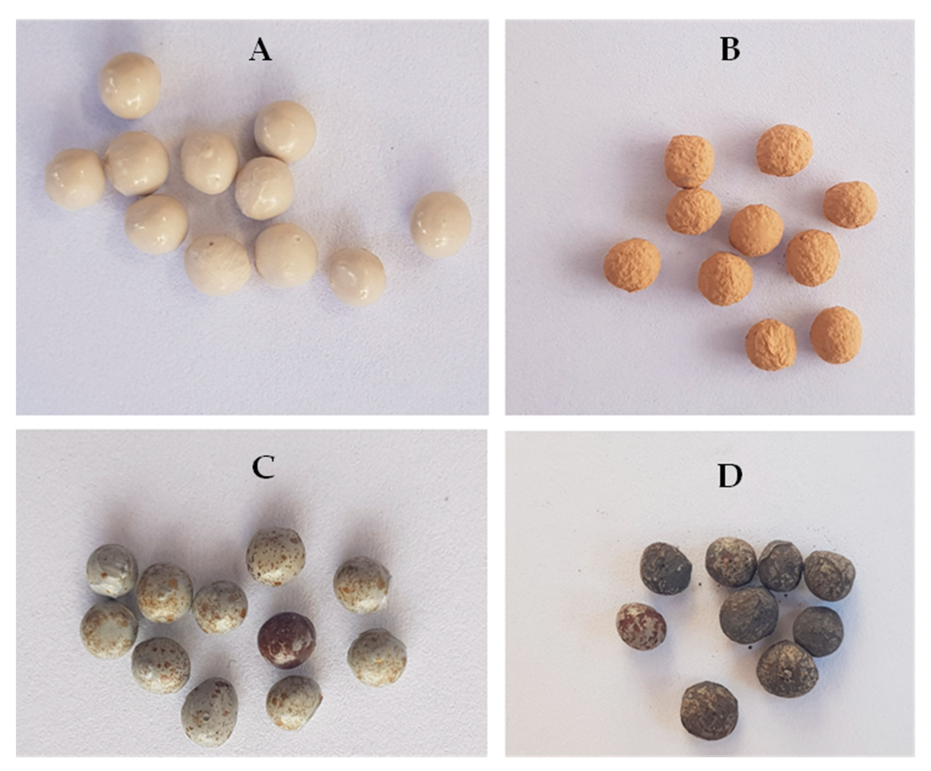
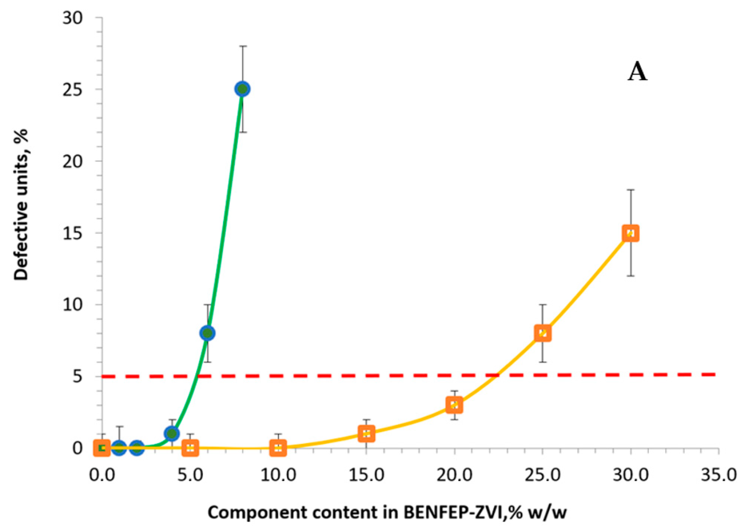
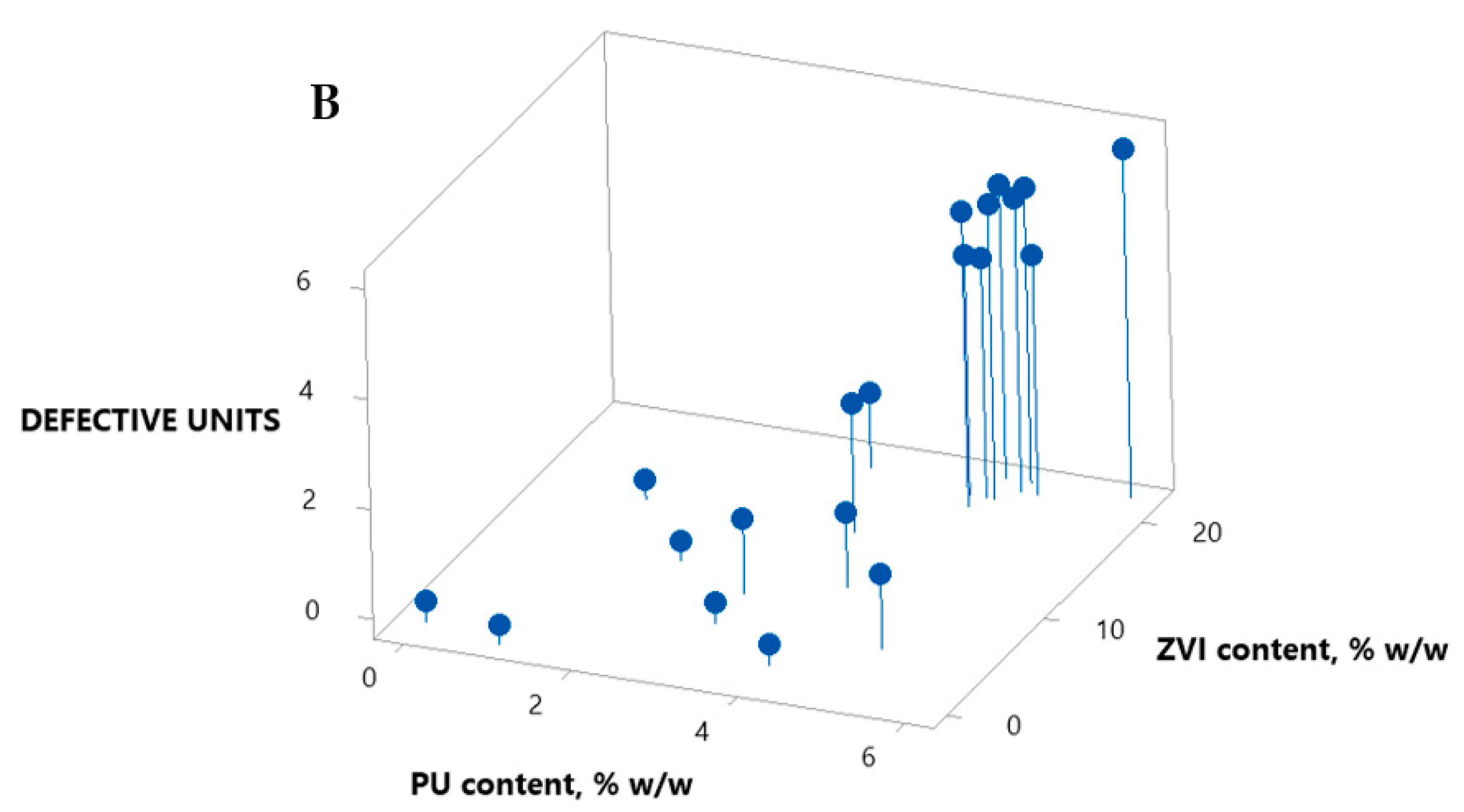
3.1. Synthesis and Characterization of Materials

Figure 1 represents the synthesis process of BENFEP, starting with the preparation of the bentonite/ZVI/PU suspension, pouring over the consolidation solution (sodium alginate at 2% m/v), coagulation, drying and calcination at 450 °C.
In the consolidation stage, the alginate solution interacts with the calcium ions in the bentonite, acquiring a rigid structure along the suspension–consolidant solution interface. The result is a sphere, the content of which corresponds to the bentonite/ZVI/PU suspension (Figure 2).
After calcination at a temperature of 450 °C, the final adsorbent product, BENFEP-ZVI, is obtained (Figure 3).
The SEM micrographs of the starting materials used for the preparation of the BENFEP adsorbent are shown in Figure 4. Figure 1A shows the typical lamellar structure of smectites, with lamellar associations of the order of 2 μm. Similarly, Table 1 summarizes the main mineral phases determined via XRD. In the case of PU and Fe(0), it is possible to determine the dimensions of their cross sections, which can be reflected in the characteristics of the adsorbent products generated, significantly affecting characteristics such as porosity and surface area.
Considering desirable characteristics to obtain an adsorbent material with high porosity and also high iron content, the first BENFEP synthesis tests were oriented to establish the maximum content of Polyurethane (PU) and ZVI to be used before producing ruptures in the structure of the adsorbent spheres. The results of these tests are shown in Figure 5A. The decision criterion was to increase the PU and ZVI contents in the spheres up to a concentration such that the number of defective units remained below 5% (maximum of 5 defects per 100 units). With this restriction, the maximum ratio of 5% w/w PU and 20% w/w ZVI was selected, which was used in subsequent studies. Figure 5B depicts the combined effect of PU and ZVI content on the BENFEP’s stability. Above the ratio of 5% m/m PU and 20% m/m ZVI, a significant increase in the generation of defective units was confirmed, with the understanding that the combination of both components above the specified amounts promoted the physical instability of the desired product.
Using van ’t Hoff’s assumptions, it was possible to estimate the range of thermodynamic properties such as enthalpy, entropy and Gibbs free energy of the adsorption processes studied. For this purpose, adsorptive capacity tests of the samples were carried out at three temperatures (25, 40 and 60 °C) in accordance with the work of other authors where three temperatures were also explored, which were sufficient for the interpretation of the adsorption process based on an approximation to its thermodynamics [52]. Starting from an initial arsenic(V) concentration of 1 mg/L, the final concentration after the adsorption process was determined, estimating the amount of arsenic removed from the solution. With this information, a lnKc versus 1/T graph was plotted, calculating the required thermodynamic parameters.

3.2. Porosity and Surface Area

Salts with low relative humidities were selected because they give better results than salts with high relative humidities. Adsorption isotherms were plotted to obtain the volume in monolayer coverage (Vm). The slope of the figures gave 1/Vm, which was then used to obtain the surface area using Equation (3) [54]: Sg = 3897.63 Vm (m2/g).
The results obtained show that the BENFEP synthesis process significantly increases the porosity and surface area parameters. In the case of natural bentonite, it has a porosity of 22% and a surface area of 110 m2/g. The synthesized adsorbent, BENFEP-ZVI, increased the porosity of its starting materials to reach a porosity of 45% and a surface area of 173 m2/g, i.e., increases of 104% and 57%, respectively. These results agree with those reported by Mandal et al. [55], who, during the development of a new zirconium polyacrylamide hybrid material (ZrPACM-43), were able to relate the increase in arsenic removal to the increase in porosity and surface area of the final product, as a result of the synthesis process.
Thus, the increase in the percentage of arsenic removal could be attributed to the availability of a greater number of adsorption sites in the solid phase. The availability of specific surface area and micropore volume plays a vital role in the surface adsorption process.

3.3. pH Effect

The pH of the solution can significantly affect the As(V) removal process, employing BENFEP-ZVI adsorbent, as it affects factors such as surface charge and adsorbent morphology, along with the speciation of arsenic in aqueous solution [56].
Figure 6 shows the removal of As(V) at different pH values (5–9); it can be observed that, from the pH in the range of 5–8, there is an increase in the removal of As(V), which drops considerably at pH 9.
This decrease is a consequence of the increase in electrical repulsion due to the formation of a layer of iron oxide-hydroxides on the adsorbent surface at alkaline pH (self-passivation). In an acidic or slightly alkaline solution, there is a significantly higher population of H+ ions, which promotes the continuous oxidation of Fe(0), increasing the concentration of Fe(II) and Fe(III) in solution. This allows the generation of greater amounts of iron oxide-hydroxides, which in turn increase the elimination of As(V).
Different studies have revealed that pH plays an important role in As(V) ion species and their adsorption capacity on ZVI [57]. These investigations suggested that with increasing solution pH, the adsorption capacity of As(V) on ZVI gradually decreases, and the main reason has been attributed to electrostatic interactions [58,59]. In the pH range of 5–7, the dominant form of As(V) is H2AsO4, a negatively charged ion [60], while the surface of nZVI is positively charged. The opposite charges between the adsorbate and adsorbent will lead to enhanced arsenic removal through electrostatic attractive force. As the pH increases further, the dominant form of As(V) changes to HAsO42−, while the surface of ZVI becomes negatively charged. Therefore, the electrostatic repulsive force would result in a decrease in As(V) adsorption.
On the other hand, it is worth noting that pH can also affect the corrosion of ZVI in solution [57,61]. Previous studies have shown that pH strongly influences the redox reactions occurring on the ZVI surface by accelerating corrosion at low pH and passivating the iron surface at high pH through the formation of iron hydro(oxides) [57,62]. Investigation revealed that ZVI corrosion products include lepidocrocite (γ-FeOOH), magnetite (Fe3O4) and/or maghemite (α-Fe2O3), each having different adsorption capacity toward arsenic. In this context, it has been reported that magnetite shows higher adsorption affinity for As than lepidocrocite [63,64,65]. This shows that the interactions and dissociation between As(V) and ZVI cannot be simply attributed to electrostatic interaction. However, how pH affects the formation of the oxide layer on the nZVI surface is not fully understood [62], let alone the systematic evaluation of the contribution of phases to As(V) adsorption at varied pH. Therefore, the mechanisms of pH influence on arsenic removal by nZVI, when considering influencing factors including electrostatic interaction and the corresponding corrosion phases of nZVI, are still cause for investigation.
In the present study, and considering the results obtained, BENFEP-ZVI presented good As(V) adsorption performances in the pH range of 5–8. Likewise, BENFEP-ZVI contains important contents of magnetite (8.43%), magnesioferrite (12.33%) and hematite (13.72%) phases, minerals formed since the synthesis stage and that increased arsenic removal under the conditions of the study (Table 1).
The point of zero charge, PZC, is defined as the pH value at which the total net charge (external and internal) of the particles on the surface of the adsorbent material is neutral, i.e., the number of positive and negative sites is equal. This parameter is very valuable in determining the particular affinity of a given adsorbent for a specific adsorbate. With respect to PZC, the following results were obtained for BENFEP calcined at 450 °C (Figure 3B,D): BENFEP-ZVI, 0% Fe, pH = 7.6 and BENFEP-ZVI, 20% Fe, pH = 7.3. The slight variation in the zero charge point with respect to the value of 7.3 corresponding to BENFEP-ZVI (20% Fe) may be associated with the substitution of silicon atoms, which generates a change in the charges [65].

3.4. Adsorption Isotherm Studies

The adsorption isotherms were analyzed using the Langmuir and Freundlich models (Equations (5) and (6)), and correlation coefficients were determined to evaluate the best fit. Adsorption isotherms show the interaction of the adsorbate with the adsorbent and provide information on the adsorption capacity of a specific adsorbent material. The linear forms of the Langmuir and Freundlich adsorption models were evaluated by using the correlation coefficients (R2). In both cases, the adsorption process of As(V) was performed at different pH values between 5 and 9. The Langmuir model presented R2 values in the range of 0.981–0.997, while the Freundlich model presented lower R2 values, in the range of 0.915–0.931. Based on these results, it was concluded that the model that fit the experimental data was the Langmuir model. In this model, the maximum adsorption capacity (qmax) of BENFEP-ZVI was in the range of 1.44 (pH 9.0) to 4.25 (pH 5.0) mg/g.
The adsorbent BENFEP-ZVI exhibited higher As adsorption capacity compared to other reported adsorbents such as magnetic nanoparticles obtained from metal wool, qmax = 2.2 mg/g [66,67], and iron-impregnated Lapsi seed nanoparticles and stone, qmax = 2 mg/g [68]. On the other hand, the results are comparable to those presented by Rahman and Yanfu [69], who worked with magnetite-maghemite nanoparticles, obtaining values of qmax = 3.69 mg/g.

3.5. Thermodynamic Studies

The thermodynamic parameters Gibbs free energy change ( G 0 ), enthalpy change ( H 0 ) and entropy change ( S 0 ) can predict the feasibility and nature of the adsorption process. The thermodynamic parameters evaluated from Equations (7)–(9) are listed in Table 2. From the plots of ln Kd vs. 1/T, the parameters H 0 and S 0 were calculated, using the slope and the intercept, respectively. Negative values of G 0 indicated that the adsorption process on BENFEP-ZVI was feasible and thermodynamically spontaneous. The ( G 0 values ranged from −12.19 to −12.13 kJ/mol, indicating that the mechanism was feasible and thermodynamically spontaneous in the temperature range of 298–333 K [8]. The H 0 was negative, reflecting that the process was exothermic in nature, while the S 0 value was negative, indicating a decrease in randomness at the solution–solid interface during adsorption [70,71], a product of the loss of freedom upon binding on the adsorbent surface.

3.6. Adsorbent Regeneration

The technologies employed for arsenic removal from water are largely based on the use of adsorbents, due to their simplicity and efficiency. Current practice is to replace the media when they no longer reduce arsenic below the maximum contaminant level of 10 μg/L. However, medium replacement generally accounts for approximately 80% of the total operating and maintenance costs of the water treatment process [72,73]. One potential option to reduce the cost is in situ regeneration and reuse of media [74,75]. To evaluate the regeneration option of the BENFEP-ZVI adsorbent, regeneration tests were performed using NaOH wash solutions of 1, 3 and 5% w/v concentration, and subsequent rinsing with deionized water until no alkaline response was observed in the pH measurement. After regeneration, arsenic adsorption tests were performed under the same optimized conditions: As(V) concentration 1 mg/L, 1.5 g/L BENFEP, pH adjusted to 7.0, contact time of 1 h. The results of this test indicate that a caustic regeneration process and subsequent rinsing of the adsorbent with deionized water was effective in removing arsenic and other contaminants from the depleted medium (Table 3).

3.7. Natural Water Sample Test

The Camarones River is a water system in which the physicochemical characteristics vary seasonally. Its waters present high levels of arsenic, with an average concentration 100 times higher than the WHO recommended value of 10 µg/L [16,76]. Table 4 presents the physicochemical parameters of a point sample of water from the Camarones River before and after being subjected to the adsorption process. The sample showed a pH value of 7.5 and conductivity higher than 1.9 mS/cm. Additionally, a low iron concentration was found in the Camarones River water sample (<0.10 mg/L).
The most likely arsenic oxidation state is +5, according to previously reported results from the Camarones River waters using HPLC-AAS and HPLC-ICP-MS [77,78]. The arsenic adsorption levels in these waters were 99%, indicating that the proposed process presents adequate robustness, allowing the treatment of waters with high salinity levels. It was observed that more than 95% of the adsorption of As(V) in BENFEP occurred in contact times of less than 30 min (Figure 7).
Table 4. Physicochemical parameters of Camarones river water before and after treatment using BENFEP-ZVI.
Parameters UnitBefore TreatmentAfter
Treatment
Test
Method *
Electrical conductivity mS/cm1.90 ± 0.021.94 ± 0.03SMWW 2510B
SulfatesSO42−mg/L340 ± 10325 ± 8SMWW 4500-SO42-D
ChlorideClmg/L350 ± 5332 ± 6SMWW 4500-Cl-B
CalciumCamg/L310 ± 3323 ± 3SMWW 3111B
IronFemg/L<0.1<0.1SMWW 3111B
ManganeseMnmg/L<0.1<0.1SMWW 3111B
CopperCumg/L<0.1<0.1SMWW 3111B
ZincZnmg/L<0.1<0.1SMWW 3111B
LeadPbmg/L<0.1<0.1SMWW 3111B
ChromiumCrmg/L<0.1<0.1SMWW 3111B
Total dissolved solids mg/L1750 ± 61823 ± 9SISS-ME-31-2007
BoronBmg/L3.1 ± 0.22.8 ± 0.15ISO9390.1990
Total arsenicAsmg/L1.0 ± <0.010 ± 0.009SMWW 3114C
Note: * SMWW: Standard Methods for Examination of Water and Wastewater [79].

4. Conclusions

It was possible to establish that the BENFEP adsorbent is a good alternative as a low-cost adsorbent to reduce the concentration of As(V) in water. Tests were carried out with both synthetic and natural water, and it was observed that more than 95% of the adsorption of As(V) in BENFEP occurred in contact times of less than 30 min. The tests with real water samples (Camarones river) established that the proposed process is robust and efficient for the treatment of water with high levels of dissolved salts. The maximum As(V) removal efficiency was observed at a pH value in the range of 5 to 8. In the isotherm studies, the experimental data established a good fit to the Langmuir adsorption model, indicating that the adsorbent has mainly homogeneous sites on its surfaces. The thermodynamic results showed that the adsorption process was feasible, spontaneous and exothermic.
Finally, it is essential to highlight that there was no deterioration in water quality after adsorption of As(V) using BENFEP as adsorbent. This is essential for its application in small-scale water treatment systems, particularly in isolated rural areas.

Author Contributions

Conceptualization, L.C.-P. and J.A.-C.; methodology, J.A.-C.; software, J.A.-C.; validation, L.C.-P. and J.A.-C.; formal analysis, J.A.-C.; investigation, J.A.-C.; writing—original draft preparation, J.A.-C.; writing—review and editing, L.C.-P. and J.A.-C.; visualization, L.C.-P. All authors have read and agreed to the published version of the manuscript.

Funding

The authors wish to express their thanks for the support of the Project Fondecyt Regular N°1201314/ANID, Agencia Nacional de Investigación y Desarrollo, Ministerio de Ciencia, Tecnología, Conocimiento e Innovación, Gobierno de Chile.

Institutional Review Board Statement

Not applicable.

Informed Consent Statement

Not applicable.

Data Availability Statement

Not applicable.

Acknowledgments

The authors wish to express their gratitude for the support of the Project Fondecyt Regular N°1201314/ANID and Solar Energy Research Center, SERC-Chile ANID/FONDAP/1522A0006.

Conflicts of Interest

The authors declare no conflict of interest.

References

  1. Lan, L.E.; Reina, F.D.; De Seta, G.E.; Meichtry, J.M.; Litter, M.I. Comparison between Different Technologies (Zerovalent Iron, Coagulation-Flocculation, Adsorption) for Arsenic Treatment at High Concentrations. Water 2023, 15, 1481. [Google Scholar] [CrossRef]
  2. Chowdhury, S.; Mazumder, M.A.J.; Al-Attas, O.; Husain, T. Heavy metals in drinking water: Occurrences, implications, and future needs in developing countries. Sci. Total Environ. 2016, 569–570, 476–488. [Google Scholar] [CrossRef]
  3. National Academy of Sciences (NAS). Arsenic in Drinking Water; National Academy of Sciences: Washington, DC, USA, 2001. [Google Scholar]
  4. Nordstrom, D.; Alpers, C. Negative pH, efflorescent mineralogy, and consequences for environmental restoration at the Iron Mountain Superfund site California. Proc. Natl. Acad. Sci. USA 1999, 96, 3455–3462. [Google Scholar] [CrossRef]
  5. Agency for Toxic Substances and Disease Registry, ATSDR, Addendum to the Toxicological Profile for Arsenic. 2016. Available online: https://www.atsdr.cdc.gov/substances/toxsubstance.asp?toxid=3 (accessed on 12 June 2023).
  6. Abejon, R.; Garea, A. A bibliometric analysis of research on arsenic in drinking water during the 1992–2012 period: An outlook to treatment alternatives for arsenic removal. J. Water Process. Eng. 2015, 6, 105–119. [Google Scholar] [CrossRef]
  7. European Union, EU. 2014. European Union (Drinking Water) Regulations 2014. S.I. No. 122 of 2014. Available online: https://www.ecolex.org/details/legislation/european-union-drinking-water-regulations-2014-si-no-122-of-2014-lex-faoc134269/ (accessed on 12 June 2023).
  8. Kumar, A.; Thakur, A.; Panesar, P.S. A review on the industrial wastewater with the efficient treatment techniques. Chem. Pap. 2023, 77, 4131–4163. [Google Scholar] [CrossRef]
  9. U.S. Environmental Protection Agency. USEPA, USEPA Integrated Risk Information System (IRIS) Online Database. 2016. Available online: http://www.epa.gov/iris (accessed on 12 June 2023).
  10. WHO. Guidelines for Drinking-Water Quality: Fourth Edition Incorporating the First Addendum; World Health Organization: Geneva, Switzerland, 2017; Available online: https://apps.who.int/iris/bitstream/handle/10665/254637/9789241549950-eng.pdf;jsessionid=A03BF55AAAB65FDEE990ED0001BCF997?sequence=1/ (accessed on 12 June 2023).
  11. Al Samman, M.T.; Sotelo, S.; Sánchez, J.; Rivas, B.L. Arsenic oxidation and its subsequent removal from water: An overview. Sep. Purif. Technol. 2023, 123055, 1383–5866. [Google Scholar] [CrossRef]
  12. Cornejo, L.; Acarapi, J.; Arenas, M. Development and validation of a method for simultaneous arsenic, antimony, selenium and mercury determination in plants by energy dispersive X ray fluorescence spectrometry. Interciencia 2018, 43, 425–433. [Google Scholar]
  13. Gamboa, J.; Cornejo, L.; Acarapi, J.; Squella, J. Determination of arsenic (III) by differential pulse polarography in the waters of Camarones area, Chile. J. Chil. Chem. Soc. 2013, 53, 2031–2034. [Google Scholar] [CrossRef] [Green Version]
  14. Akram, Z.; Jalali, S.; Shami, S.A.; Ahmad, L.; Batool, S.; Kalsoom, O. Adverse effects of arsenic exposure on uterine function and structure in female rat. Exp. Toxicol. Pathol. 2010, 62, 451–459. [Google Scholar] [CrossRef]
  15. Cornejo, L.; Lienqueo, H.; Arenas, M.; Acarapi, J.; Yañez, J.; Mansilla, H. In field arsenic removal from natural water by zero valent iron. Environ. Pollut. 2008, 156, 827–831. [Google Scholar] [CrossRef]
  16. Cornejo, L.; Acarapi, J. Fractionation and bioavailability of arsenic in agricultural soils: Solvent extraction tests and their relevance in risk assessment. J. Environ. Sci. Health Part A 2011, 46, 1247–1258. [Google Scholar] [CrossRef]
  17. Marcela, S.; Eric, L.; Lorena, C.; Jorge, A. Elemental characterization of prehispanic rock art and arsenic in northern Chile. J. Rock Art Res. 2012, 29, 93–107. [Google Scholar]
  18. International Agency for Research on Cancer, IARC. 2016. IARC Monographs on the Evaluation of Carcinogenic Risks to Humans. Volumes 1–115. Available online: http://monographs.iarc.fr/ENG/Classification/latest_classif.php (accessed on 20 June 2021).
  19. Marshall, G.; Ferreccio, C.; Yuan, Y.; Michael, N.B.; Steinmaus, C.; Selvin, S.; Liaw, J.; Smith, H.A. Fifty-year study of lung and bladder cancer mortality in Chile related to arsenic in drinking water. J. Natl. Cancer Inst. 2007, 99, 920–928. [Google Scholar] [CrossRef] [Green Version]
  20. Lisabeth, L.D.; Hyeong, A.J.; Chen, J.J.; Shawnita, S.J.; Burke, J.F.; Meliker, J.R. Arsenic in drinking water and stroke hospitalizations in Michigan. Stroke 2010, 41, 2499–2504. [Google Scholar] [CrossRef] [Green Version]
  21. Islam, R.; Zhao, L.; Zhang, X.; Liu, L.Z. MiR-218-5p/EGFR Signaling in Arsenic-Induced Carcinogenesis. Cancers 2023, 15, 1204. [Google Scholar] [CrossRef]
  22. Asere, T.G.; Stevens, C.V.; Laing, G.D. Use of (modified) natural adsorbents for arsenic remediation: A review. Sci. Total Environ. 2019, 676, 706–720. [Google Scholar] [CrossRef]
  23. Auta, M.; Hameed, B.H. Modified mesoporous clay adsorbent for adsorption isotherm and kinetics of methylene blue. Chem. Eng. J. 2012, 198, 219–227. [Google Scholar] [CrossRef]
  24. Awual, M.R.; Hossain, M.A.; Shenashen, M.A.; Yaita, T.; Suzuki, S.; Jyo, A. Evaluating of arsenic(V) removal from water by weak-base anion exchange adsorbents. Environ. Sci. Pollut. R. 2013, 20, 421–430. [Google Scholar] [CrossRef]
  25. Jain, C.; Singh, R. Technological options for the removal of arsenic with special reference to South East Asia. J. Environ. Manag. 2012, 107, 1–18. [Google Scholar] [CrossRef] [Green Version]
  26. Dilpazeer, F.; Munir, M.; Baloch, M.Y.J.; Shafiq, I.; Iqbal, J.; Saeed, M.; Abbas, M.M.; Shafique, S.; Aziz, K.H.H.; Mustafa, A.; et al. A Comprehensive Review of the Latest Advancements in Controlling Arsenic Contaminants in Groundwater. Water 2023, 15, 478. [Google Scholar] [CrossRef]
  27. Oscarson, D.; Huang, P.; Liaw, W.; Hammer, U. Kinetics of oxidation of arsenite by various manganese dioxides. Soil Sci. Soc. Am. J. 1983, 47, 644–648. [Google Scholar] [CrossRef]
  28. Ferguson, J.; Gavis, J. Review of the arsenic cycle in natural waters. Water Res. 1972, 6, 1259–1274. [Google Scholar] [CrossRef]
  29. Hassan, H. A review on different arsenic removal techniques used for decontamination of drinking water. Environ. Pollut. Bioavailab. 2023, 35, 2165964. [Google Scholar] [CrossRef]
  30. Mohan, D.; Pittman, C.U. Arsenic removal from water/wastewater using adsorbents. A critical review. J. Hazard. Mater. 2007, 142, 1–53. [Google Scholar] [CrossRef]
  31. Murphy, T.; Guo, J. Aquatic Arsenic Toxicity and Treatment; Backhuys Publishers: Leiden, The Netherlands, 2003. [Google Scholar]
  32. Dutta, S.; Manna, K.; Srivastava, S.K.; Gupta, A.K.; Yadav, M.K. Hollow polyaniline Microsphere/Fe3O4 nanocomposite as an Effective Adsorbent for Removal of Arsenic from Water. Sci. Rep. 2020, 10, 4982. [Google Scholar] [CrossRef] [Green Version]
  33. Gao, Q.; Feng, Z.; He, Y.; Hou, Y.; Ren, H.; Su, M.; Ni, L.; Liu, Z. Pyrolysis self-activation: An environmentally friendly method to transform biowaste into activated carbon for arsenic removal. Bioresour. Technol. 2023, 368, 128353. [Google Scholar] [CrossRef]
  34. Grba, N.; Baldermann, A.; Dietzel, M. Novel green technology for wastewater treatment: Geo-material/geopolymer applications for heavy metal removal from aquatic media. Int. J. Sediment Res. 2023, 38, 33–48. [Google Scholar] [CrossRef]
  35. Thirunavukkarasu, O.; Viraraghavan, T.; Subramanian, K. Arsenic removal from drinking water using granular ferric hydroxide. Water SA 2003, 29, 161–170. [Google Scholar] [CrossRef] [Green Version]
  36. Altundogan, H.; Altundogan, S.; Tumen, F.; Bildik, M. Arsenic adsorption from aqueous solutions by activated red mud. Waste Manage. 2002, 22, 357–363. [Google Scholar] [CrossRef]
  37. Do, D. Adsorption Analysis: Equilibria and Kinetics; Imperial College Press: London, UK, 1998. [Google Scholar]
  38. Livesey, N.; Huang, P. Adsorption of arsenate by soils and its relation to selected chemical properties and anions. Soil Sci. 1981, 131, 88–94. [Google Scholar] [CrossRef]
  39. Rosenblum, E.; Clifford, D. Equilibrium Arsenic Capacity of Activated Alumina [EPA-600/2-83-107]; U.S. Environmental Protection Agency: Washington, DC, USA, 1983; p. 89.
  40. Subramanian, K.; Viraraghavan, T.; Phommavong, T.; Tanjore, S. Manganese greensand for removal of arsenic in drinking water. Water Qual. Res. J. Can. 1997, 32, 551–561. [Google Scholar] [CrossRef]
  41. Zialame, A.; Jamshidi-Zanjani, A.; Darban, A.K.; Homaee, M. Arsenic removal from solution using nano-magnetic compound: Optimization modeling by response surface method. Environ. Monit. Assess 2023, 195, 136. [Google Scholar] [CrossRef]
  42. Gupta, S.; Chen, K. Arsenic removal by adsorption. J. Water Pollut. Control Fed. 1978, 50, 493–506. [Google Scholar]
  43. Han, X.; Wang, F.; Zhao, Y.; Meng, J.; Tian, G.; Wang, L.; Liang, J. Recycling of iron ore tailings into magnetic nanoparticles and nanoporous materials for the remediation of water, air and soil: A review. Environ. Chem. Lett. 2023, 21, 1005–1028. [Google Scholar] [CrossRef]
  44. Maeda, S.; Ohki, A.; Saikoji, S.; Naka, K. Iron(III) hydroxide-loaded coral limestone as an adsorbent for arsenic(III) and arsenic(V). Sep. Sci. Technol. 1992, 27, 681–689. [Google Scholar] [CrossRef]
  45. Manning, B.; Goldberg, S. Modeling arsenate competitive adsorption on kaolinite, montmorillonite and illite. Clay Clay Miner. 1996, 44, 609–623. [Google Scholar] [CrossRef]
  46. Das, T.; Bezbaruah, A. Comparative study of arsenic removal by iron-based nanomaterials: Potential candidates for field applications. Sci. Total Environ. 2021, 764, 142914. [Google Scholar] [CrossRef]
  47. Cundy, A.B.; Hopkinson, L.; Whitby, R.L.D. Use of iron-based technologies in contaminated land and groundwater remediation: A review. Sci. Total Environ. 2008, 400, 42–51. [Google Scholar] [CrossRef]
  48. Jin, H.Z.; Qiu, C.X.; Li, Y.S.; Liu, B.; Liu, J.Y.; Chen, Q.; Lu, X.F.; Li, C.X.; Wamg, Q.K. Structural and functional design of geopolymer adsorbents: A review. Tungsten 2023. [Google Scholar] [CrossRef]
  49. Diya’uddeen, B.; Mohammed, I.; Jibril, B.; Bugaje, I. Comparison of Bet and Water Adsorption Techniques. Am. J. Eng. Appl. Sci. 2013, 6, 282–285. [Google Scholar] [CrossRef]
  50. Ahmedna, M.; Johns, M.; Clark, S.; Marshall, W.; Rao, R. Potential of agricultural byproduct- based activated carbons for use in raw sugar decolourisation. J. Sci. Food Agric. 1997, 75, 117–124. [Google Scholar] [CrossRef]
  51. Akinyemi, O.P.; Taiwo, E.A. Production of activated carbon from agricultural wastes. In Proceedings of the Nigerian Society of Chemical Engineers, Warri, Nigeria, 20–24 September 2004; pp. 59–62. [Google Scholar]
  52. Jaramillo-Fierro, X.; Alvarado, H.; Montesdeoca, F.; Valarezo, E. Faujasite-Type Zeolite Obtained from Ecuadorian Clay as a Support of ZnTiO3/TiO2 NPs for Cyanide Removal in Aqueous Solutions. Int. J. Mol. Sci. 2023, 24, 9281. [Google Scholar] [CrossRef]
  53. Yadav, S.; Asthana, A.; Singh, A.K.; Chakraborty, R.; Vidya, S.S.; Md. Hasan Susan, A.B.; Carabineiro, S.A.C. Adsorption of cationic dyes, drugs and metal from aqueous solutions using a polymer composite of magnetic/β-cyclodextrin/activated charcoal/Na alginate: Isotherm, kinetics and regeneration studies. J. Hazard. Mater. 2021, 409, 124840. [Google Scholar] [CrossRef]
  54. Adefila, S.S.; Aderemi, B.O.; Ajayi, O.A.; Baderin, D.A. Comparative surface area determination using water adsorption method. Niger. J. Eng. Fac. Eng. Ahmadu Bello Univ. Zaria 2003, 11, 88–95. [Google Scholar]
  55. Mandal, S.; Kumar, M.; Kishore, R. Adsorption studies of arsenic(III) removal from water by zirconium polyacrylamide hybrid material (ZrPACM-43). Water Resour. Ind. 2013, 4, 51–67. [Google Scholar] [CrossRef] [Green Version]
  56. Thirunavukkarasu, O.; Viraraghavan, T.; Subramanian, K. Removal of arsenic in drinkingwater by iron oxide-coated sand and ferrihydrite—Batch studies. Water Qual. Res. J. Can. 2001, 36, 55–70. [Google Scholar] [CrossRef]
  57. Triszcz, M.; Porta, A.; Einschlag, F. Effect of operating conditions on iron corrosion rates in zero-valent iron systems for arsenic removal. Chem. Eng. J. 2009, 150, 431–439. [Google Scholar] [CrossRef]
  58. Giasuddin, A.; Kanel, S.; Choi, H. Adsorption of humic acid onto nanoscale zerovalent iron and its effect on arsenic removal. Environ. Sci. Technol. 2007, 41, 2022–2027. [Google Scholar] [CrossRef]
  59. Katsoyiannis, I.O.; Ruettimann, T.; Hug, S. pH Dependence of Fenton Reagent Generation and As(III) Oxidation and Removal by Corrosion of Zero Valent Iron in Aerated Water. Environ. Sci. Technol. 2008, 42, 7424–7430. [Google Scholar] [CrossRef]
  60. Smedley, P.; Kinniburgh, D. A review of the source, behaviour and distribution of arsenic in natural waters. Appl. Geochem. 2002, 17, 517–568. [Google Scholar] [CrossRef] [Green Version]
  61. Hu, B.; Ye, F.; Ren, X.; Zhao, D.; Sheng, G.; Li, H.; Ma, J.; Wang, X.; Huang, Y. X-ray absorption fine structure study of enhanced sequestration of U(VI) and Se(IV) by montmorillonite decorated zerovalent iron nanoparticles. Environ. Sci. Nano 2016, 3, 1460–1472. [Google Scholar] [CrossRef]
  62. Carroll, D.; Sleep, B.; Krol, M.; Boparai, H.; Kocur, C. Nanoscale Zero Valent Iron and Bimetallic Particles for Contaminated Site Remediation. Adv. Water Resour. 2013, 51, 104–122. [Google Scholar] [CrossRef]
  63. Wang, Y.; Morin, G.; Ona-nguema, G.; Brown, G. Arsenic(III) and Arsenic(V) Speciation during Transformation of Lepidocrocite to Magnetite. Environ. Sci. Technol. 2014, 48, 14282–14290. [Google Scholar] [CrossRef]
  64. Wu, C.; Tu, J.; Liu, W.; Zhang, J.; Chu, S.; Lu, G.; Lin, Z.; Danga, Z. The double influence mechanism of pH to the arsenic removal 2 by nano zero valent iron: Electrostatic interactions and the corrosion of Fe0. Environ. Sci. Nano 2017, 4, 1544–1552. [Google Scholar] [CrossRef]
  65. Guaya, D.; Maza, L.; Angamarca, A.; Mendoza, E.; García, L.; Valderrama, C.; Cortina, J.L. Fe3+/Mn2+ Oxy)Hydroxide Nanoparticles Loaded onto Muscovite/Zeolite Composites (Powder, Pellets and Monoliths): Phosphate Carriers from Urban Wastewater to Soil. Nanomaterials 2022, 12, 3848. [Google Scholar] [CrossRef] [PubMed]
  66. Pedersen, H.; Postma, D.; Jakobsen, R. Release of arsenic associated with the reduction and transformation of iron oxides. Geochim. Cosmochim. Acta 2006, 70, 4116–4129. [Google Scholar] [CrossRef]
  67. Alarcon, M.; Lopez, M. Technical feasibility of using magnetic nanoparticles obtained from metallic wool for arsenite (As (III)) removal from aqueous solutions. J. Nanosci. Technol. 2016, 4, 35–43. [Google Scholar]
  68. Shrestha, R.M.; Yadav, A.P.; Pokharel, B.P.; Rajbhandari, R. Preparation and Characterization of Activated Carbon from Lapsi (Choerospondias axillaris) seed stone by chemical activation with phosphoric acid. Res. J. Chem. Sci. 2012, 2, 80–86. [Google Scholar]
  69. Rahman, S.; Yanful, E. Arsenic and chromium removal by mixed magnetite-maghemite nanoparticles and the effect of phosphate on removal. J. Environ. Manag. 2010, 11, 2238–2247. [Google Scholar]
  70. Figueroa, D.; Moreno, A.; Hormaza, A. Equilibrio, termodinámica y modelos cinéticos en la adsorción de Rojo 40 sobre tuza de maíz. Rev. Medellín 2015, 14, 105–120. [Google Scholar] [CrossRef]
  71. Aksu, Z.; Tatlı, A.İ.; Tunç, Ö. A comparative adsorption/biosorption study of Acid Blue 161: Effect of temperature on equilibrium and kinetic parameters. Chem. Eng. J. 2008, 142, 23–39. [Google Scholar] [CrossRef]
  72. Sorg, T.; Wang, L.; Chen, A. Costs of Small Drinking Water Systems Removing Arsenic from Groundwater. J. Water Supply Res. Technol.—AQUA 2015, 64, 219. [Google Scholar] [CrossRef]
  73. Wang, L.; Chen, A. Costs of Arsenic Removal Technologies for Small Water Systems: U.S. EPA Arsenic Removal Technology Demonstration Program; EPA/600/R-11/090; National Risk Management Research Laboratory: Cincinnati, OH, USA, 2011. [Google Scholar]
  74. Chaudhary, B.; Farrell, J. Understanding Regeneration of Arsenate-Loaded Ferric Hydroxide-Based Adsorbents. Environ. Eng. Sci. 2015, 32, 353–360. [Google Scholar] [CrossRef] [PubMed]
  75. Sorg, T.; Chen, A.; Wang, L.; Kolisz, R. Regenerating an Arsenic Removal Iron-Bed Adsorptive Media System, Part 1: The Regeneration Process. J. Am. Water Work. Assoc. 2017, 109, 13–24. [Google Scholar] [CrossRef]
  76. Bundschuh, J.; Litter, M.; Parvez, F.; Román-Ross, G.; Nicolli, H.; Jeanc, J.; Liuj Ch López, D.; Armiental, M.; Guilherme, L.; Gomez, A.; et al. One century of arsenic exposure in Latin America: A review of history and occurrence from 14 countries. Sci. Total Environ. 2012, 429, 2–35. [Google Scholar] [CrossRef] [PubMed]
  77. Yañez, J.; Fierro, V.; Mansilla, H.; Cornejo, L.; Figueroa, L.; Barnes, R. Arsenic speciation in human hair: A new perspective for epidemiological assessment in chronic arsenicism. J. Environ. Monit. 2005, 7, 1335–1341. [Google Scholar] [CrossRef] [PubMed]
  78. Lara, F.; Cornejo, L.; Yañez, J.; Freer, J.; Mansilla, H.D. Solar-light assisted removal of Arsenic from natural water: Effect of iron and citrate concentrations. J. Chem. Technol. Biotechnol. 2006, 81, 1282–1287. [Google Scholar] [CrossRef]
  79. American Public Health Association; American Water Works Association; Water Environment Federation. Standard Methods for the Examination of Water and Wastewater, 24th ed.; Lipps, W.C., Braun-Howland, E.B., Baxter, T.E., Eds.; APHA Press: Washington, DC, USA, 2023. [Google Scholar]
Figure 1. Stages of the BENFEP synthesis process.
Water 15 02887 g001
Figure 2. Representation of structural changes and component rearrangements within BENFEP during the synthesis process. (A) one drop of Bentonite/ZVI/PU suspension falls and comes into contact with sodium alginate (2% w/w) solution. (B) The calcium ions on the surface of the sphere bind to the alginate molecules, initiating the consolidation and solidification of the sphere. (C) During the drying stage (24–48 h, 40 °C), the water molecules are eliminated from inside the sphere, generating a solid, low-moisture intermediate product, suitable for the final calcination stage. With calcination the elimination of alginate and PU molecules is achieved, obtaining a sphere with a porous structure (BENFEP).
Water 15 02887 g002
Figure 3. BENFEP-ZVI spheres synthesized in the present study. (A) BENFEP-ZVI, 0% Fe, not calcined. (B) BENFEP-ZVI, 0% Fe, calcined at 450 °C. (C) BENFEP-ZVI, 20% Fe, without calcination. (D) BENFEP-ZVI, 20% Fe, calcined at 450 °C.
Water 15 02887 g003
Figure 4. Cross-sectional SEM images of BENFEP-ZVI sphere, 20% Fe. (Left) uncalcined sphere. (Right) sphere calcined at 450 °C.
Water 15 02887 g004
Figure 5. (A): Plot of independent effect of PU (green) and ZVI (yellow) content versus number of defective BENFEP units. The criterion used is to select the PU and ZVI content in such a way that the number of defective units is less than 5% of the total: 5% w/w PU and 20% w/w ZVI maximum content, respectively. Circle symbols: PU content. Square symbols: content of ZVI. (B): Joint effect of PU and ZVI content on the number of defective units. To keep the number of defective BENFEP units below 5%, the contents of PU and ZVI in the spheres must be less than 5% w/w PU and 20% w/w ZVI.
Water 15 02887 g005aWater 15 02887 g005b
Figure 6. Langmuir adsorption plots for the adsorption of As(V) on BENFEP, at different pH values.
Water 15 02887 g006
Figure 7. Arsenic removal curve as a function of time. Conditions: Test in batch system, initial solution conc. As(V) = 1.0 mg/L; adsorbent mass = 1.5 g; solution volume 100 mL; BENFEP-ZVI, 20% Fe, pH solution adjusted to 7.5 with buffer (HCO3/CO32−). Each point corresponds to the mean of three determinations and its respective standard deviation (bar).
Water 15 02887 g007
Table 1. Main mineral phases and elemental composition of materials used in this work.
X-ray Diffraction *
BentoniteBENFEP-ZVI
Montmorillonite22.5821.92
Quartz4.2724.92
Anhydrite10.0216.87
Magnetite<18.43
Magnesioferrite<112.33
Cristobalita<11.78
Hematite<113.72
Andesita13.31<1
Muscovite41.78<1
X-ray Fluorescence (EDXRF) *
BentoniteZVIPolyurethane (PU)
Silicon79.70<0.001<0.001
Sulfur7.91<0.001<0.001
Potassium4.35<0.001<0.001
Iron 3.8198.80<0.001
Calcium1.98<0.0010.16
Titanium1.07<0.001<0.001
Manganese<0.0010.94<0.001
Strontium0.76<0.001<0.001
Arsenic0.25<0.001<0.001
Lead<0.001<0.001<0.001
Note: * Expressed on a dry basis and % w/w.
Table 2. Thermodynamic parameters of the As(V) adsorption process on BENFEP-ZVI.
G 0 (kJ/mol) at Studied Temperature (K)
H 0
(kJ/mol)
S 0
(kJ/mol ∗ K)
298313333
−12.66−0.002−12.19−12.15−12.13
Table 3. Arsenic removal with the use of regenerated sorbent media.
SampleNaOHFirst
Regeneration
Second
Regeneration
Third
Regeneration
(% w/v)(%)(%)(%)
183.281.180.2
BENFEP 20393.092.390.1
599.399.098.5
Disclaimer/Publisher’s Note: The statements, opinions and data contained in all publications are solely those of the individual author(s) and contributor(s) and not of MDPI and/or the editor(s). MDPI and/or the editor(s) disclaim responsibility for any injury to people or property resulting from any ideas, methods, instructions or products referred to in the content.

