Article

Simulation Study on Seepage Patterns of Geothermal Reinjection in Carbonate Thermal Reservoir and Geothermal Doublet Well Patterns in Xiong’an New Area

1
School of Geosciences, Yangtze University, University Road 111, Caidian Street, Caidian District, Wuhan 430100, China
2
China Renewable Energy Engineering Institute, Liupukang North Street 2, Xicheng District, Beijing 100120, China
3
The Institute of Hydrogeology and Environmental Geology, Chinese Academy of Geological Sciences, Shijiazhuang 050061, China
4
Technology Innovation Center for Geothermal & Hot Dry Rock Exploration and Development, Ministry of Natural Resources, Shijiazhuang 050061, China
5
New Energy Institute, Sinopec Star, Beijing 100083, China
*
Author to whom correspondence should be addressed.
Water 2023, 15(15), 2683; https://doi.org/10.3390/w15152683
Submission received: 26 April 2023 / Revised: 21 July 2023 / Accepted: 21 July 2023 / Published: 25 July 2023
(This article belongs to the Special Issue Hydrochemical Characteristics of Geothermal Water)

Abstract

:
The karst fissures of the carbonate thermal reservoir in Xiong’an New Area have developed, and they have the advantages of a concentrated distribution, shallow burial, large water volume, and easy recharge, which are conducive to the development and utilization of geothermal resources. This paper took the carbonate thermal reservoir in Xiong’an New Area as the research object and studied the characteristics of the seepage patterns and temperature distribution in thermal storage with different well arrangements and recharge methods by laser etching the micromodel of the carbonate thermal reservoir and simulating the recharge methods. The paper established a numerical model of the resettlement area of Xiong’an New Area based on the production data and the current recharge well pattern, and it proposed a plan for a geothermal doublet well arrangement. The results showed that the injection speed and angle significantly influenced the seepage of injected water in the fractured reservoir. The injection speed correlated with the breakthrough time and swept area. The breakthrough time plummeted as the injection speed increased, and the swept area crept up as the injection-fracture dip increased. The well arrangements also impacted the seepage patterns. The well pattern of two injectors and three producers was relatively suitable for geothermal reinjection, and it was more appropriate to choose the maximum injection-fracture dip because of the largest swept area. Factors that affected the sustainable development and utilization of geothermal fields included the well pattern arrangement, well spacing, injection and production volumes, and the temperature of the injected water. Based on the modeling, it is recommended that the well spacing be greater than 500 m, and the injection and production volumes less than 110 m3/h in the resettlement area of Xiong’an New Area. Moreover, a vertical fracture well is recommended to reduce thermal breakthroughs.

1. Introduction

China is well endowed with geothermal resources that are widely distributed with distinctive distribution patterns and regional characteristics. In particular, the large sedimentary basins have wealthy reserves and thus have the greatest potential for geothermal resource development [1,2]. Xiong’an New Area is located in the North China Basin, where the karst fissures of the bedrock thermal storage have the advantages of a concentrated distribution, shallow burial, large water volume, and easy recharge, which are conducive to development and utilization [3,4,5]. Geothermal reinjection is critical to ensuring the sustainable development and utilization of geothermal resources. It can maintain a relatively stable pressure for thermal storage, reduce the pollution caused by geothermal tailwater discharge, and realize sustainable development. The production capacity of Geysers geothermal fields in the United States has improved significantly since geothermal reinjection in 1970 [6]. The Larderello geothermal power station in Italy began geothermal reinjection in 1974; the reservoir pressure has recovered somewhat, and production increased significantly [7]. In 1995, “two production and one injection” was implemented in the Paris Basin geothermal field; the temperature of the producing well has not decreased according to years of data [8].
In addition to effectively recharging and stabilizing the thermal storage pressure, the rechargeable geothermal fluid has no irreversible effects on the thermal storage temperature or the chemical environment. Geothermal resources are developed mainly for geothermal heating in China. Therefore, dynamic changes in the water levels are affected by artificial exploitation, and the overall water levels in most areas are declining. Reinjection can slow down the rate of the water level decline. Geothermal reinjection recharges the low-temperature water in the thermal reservoir after heat extraction, which inevitably causes a local fluid-temperature decrease in the thermal reservoir. In the geothermal system, the injected water reaches the production well too quickly, which causes a reduction in the production well temperature. It is the thermal breakthrough; reasonable well network layout can avoid the occurrence of thermal breakthrough. Diazr et al. [9] proposed that infield reinjection near the production well could effectively restore the thermal reservoir pressure, but it needs to choose the appropriate well distance to maintain the balance between the reservoir pressure and the thermal breakthrough. However, the Daye thermal field in Japan is a low-heat reservoir and cracks are widely distributed; then the injection well is arranged slightly far from the production well to reduce the risk of heat storage cooling [10]. Data from the Icelandic Reykjanes geothermal field show that infield reinjection can reduce the rate of the pressure drop in the thermal reservoir [11]. The simulation study of the thermal reservoir in Tianjin of China shows that the production and injection spacing of 850 m is not conducive to the recovery of the reservoir water level flow field [12]. Feng et al. [13] analyzed the monitoring data of multiyear water levels and temperatures in Northwest Shandong Province. The research showed that the annual rate of water level decline slowed by 50%, but the temperature around the injection wells dropped after stable reinjection in the heating season for three consecutive years. Ruan analyzed the monitoring data of the multiyear water levels and temperatures of geothermal wells in Tianjin and concluded that reinjection could significantly mitigate the water level decline in geothermal reservoirs [14].
Many researchers have studied seepage patterns in reservoir fractures by numerical simulations. Freedman and Nam et al. [15,16] analyzed the migration and heat transfer in the geothermal reservoir by numerical simulations. Ilyushin and Anastasiya et al. [17,18] analyzed the technological process of mineral water extraction, and constructed a mathematical model of hydrogeological processes occurring under random disturbances. Mahmoodpour et al. [19] found that, for a given discrete fracture network, the fracture aperture, rock matrix permeability, and wellbore radius are the most influential parameters controlling the thermal breakthrough time, production-well mass flux, and overall energy recovery. Some researchers used COMSOL to simulate the influence of fracture distribution characteristics and the layout of well mesh on thermal performance [20,21,22]. Fan et al. [23] analyzed the influence of the parameters of injection and production of five spot patterns by the Laplace. In this paper, we used Petrel and tNavigator software; construction modeling, matrix attribute modeling, and fracture modeling were performed, and the dual property coupling via the Simulation module. Finally, we constructed the model of geothermal well patterns in Xiong’an New Area.
This paper took the carbonate thermal reservoir in Xiong’an New Area as the research object. It studied the effect of different well patterns and reinjection methods on the seepage patterns of the injected water in the fractured reservoir with a thermal reservoir micromodel and recharge methods. Moreover, it suggested a geothermal doublet well pattern in Xiong’an New Area through numerical simulations.

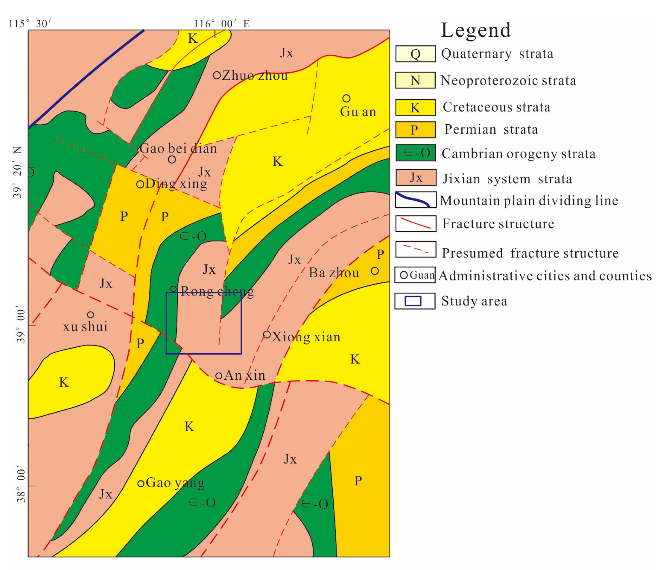
2. Geological Settings

Xiong’an New Area is located in the Jizhong depression of the Bohai Bay Basin in the northern North China Plain (Figure 1). It is a depression in the western Bohai Bay Rift Basin, uplifting against the Yanshan Mountains to the north, the Xingheng Mountains to the south, the Taihang Mountains to the west, and Cang County to the east. Its range has an NE–SW trend, and it can be divided into 12 depressions and 6 uplifts, including Rao Yang, Ba County, Langgu, Shu Lu, Shen County, and Jin County. From the Paleoproterozoic to the end of the Triassic, the Jizhong depression developed a relatively stable set of carbonate and clastic sediments, changing from marine to paralic and continental facies, with high stability, a wide distribution, and mild tectonic movements and magmatism (mainly oscillatory movements). Since the Jurassic, it has developed a set of terrestrial clastic rocks with wild tectonic movements and magmatism (mainly subsidence and deposition). The depressions and uplifts in the Cenozoic Erathem deposit are arranged in a cloak-like manner. The unconsolidated quaternary layer is nearly parallel to the sandstones, conglomerates, and mudstones in the Neogene System, and the dip of those of the Paleogene System is gentle. The underlying formation is Cretaceous, Jurassic, Permian, Carboniferous, Ordovician, Cambrian, Qingbaikouan, Jx and Ch Systems, and Archean metamorphic rocks [24,25].
Xiong’an New Area is mainly influenced by NE-trending faults, followed by EW-, NNE-, and NW-trending faults, including Niudong Fault, Rongcheng Fault, Daxing Fault, and Niunan Fault. Among them, the first three are long-term faults that formed in the late Yanshan Movement and intensified in the early Himalayan Movement. According to the regional geological data, it is believed that the NE-trending faults have changed from compressional to tensional.
The thermal reservoir of carbonate is the subject of this study. The Wumishan Formation of the Jx System in Xiong’an New Area has been deposited for a long time and has experienced multiple phases of tectonic movements, with highly developed karst fissures. The early fissures are mainly diagenetic fractures, developed during the dry Qinyu and Hercynian movements, which were relatively stable uplift and subsidence movements. During this period, the fissures were mainly shear fractures, with several fracture systems, high density, and a small scale, and often cut by the faults of other fracture systems, facilitating the formation of the Qinyu karst. The middle fissures are mainly tectonic fractures, developed during the Indosinian and Yanshanian, and especially during the Yanshanian, with the principal compressive stress in the NW–SE direction. A series of fissures were formed, mainly in the NE and NNE directions, facilitating the formation of the Indosinian and Yanshanian karst. The late fissures are mainly tectonic fractures of the early Himalayan period and nontectonic fractures of the late Himalayan period. The principal compressive stress is in the NEE–SWW direction, forming fissures in the NNW–SSE direction and facilitating the formation of the Himalayan karst [26].
The Wumishan Formation in Xiong’an New Area has been affected by diagenesis, tectonic activity, weathering, and tectonic denudation, and leaching and hydrothermal activity in multiple periods, forming fractured karst reservoirs characterized by pores, holes, and seams. The lithology is mainly dolomite with flint strip, huge thick laminated dolomite, asphaltentic dolomite, and silty mudomite with thin brown–red and gray–green mudstone. The debris is mostly flaky. In the upper part, the degree of water erosion is higher, the core is broken, and the weathering degree is higher, which affects the fissure development. The effective thermal reservoir is mainly distributed at 300–400 m at the top of Jixian system strata, with a thickness ratio of 20~40%, a fissure of 4~12% and a water temperature of 50~80 °C. The fissures in the strata are not evenly distributed, and the volume of the fissure space only accounts for parts per thousand of the rock mass. The fissures with water storage and conduction abilities generally appear in layers in the rock mass, forming local fractured zones. The highly developed fracture systems in the Wuzhishan Formation in Xiong’an New Area and the in-situ stress help open the fissures. The great internal connectivity of the reservoir leads to a water-conducting channel and storage space for geothermal water, providing favorable conditions for the enrichment of the karst geothermal resources in the study area [27,28].
Figure 1. Geological map of study area in Xiong’An New Area [29].
Water 15 02683 g001

3. Experimental Method

This section is divided by subheadings. It should provide a concise and precise description of the experimental results, their interpretation, as well as the experimental conclusions that can be drawn.

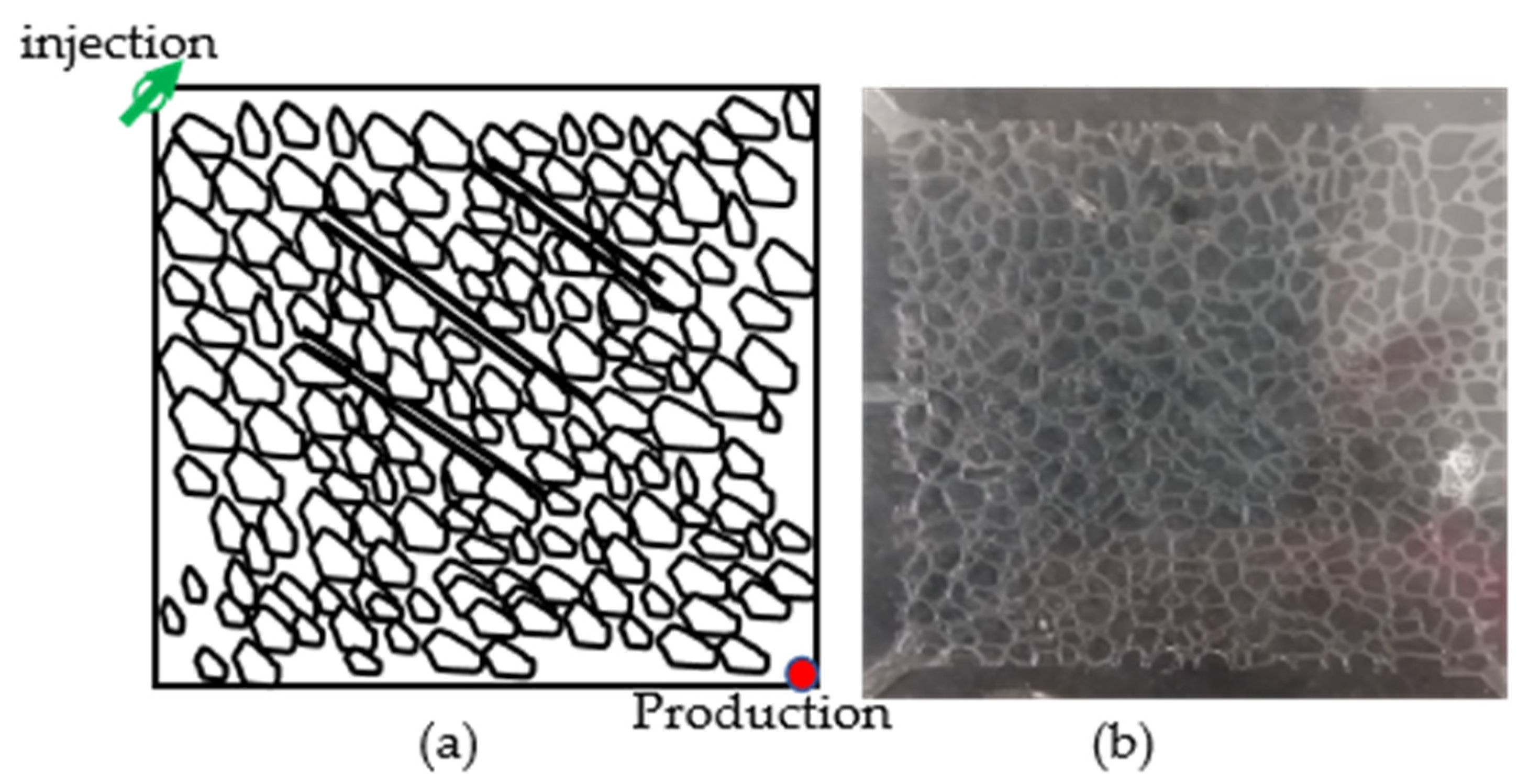
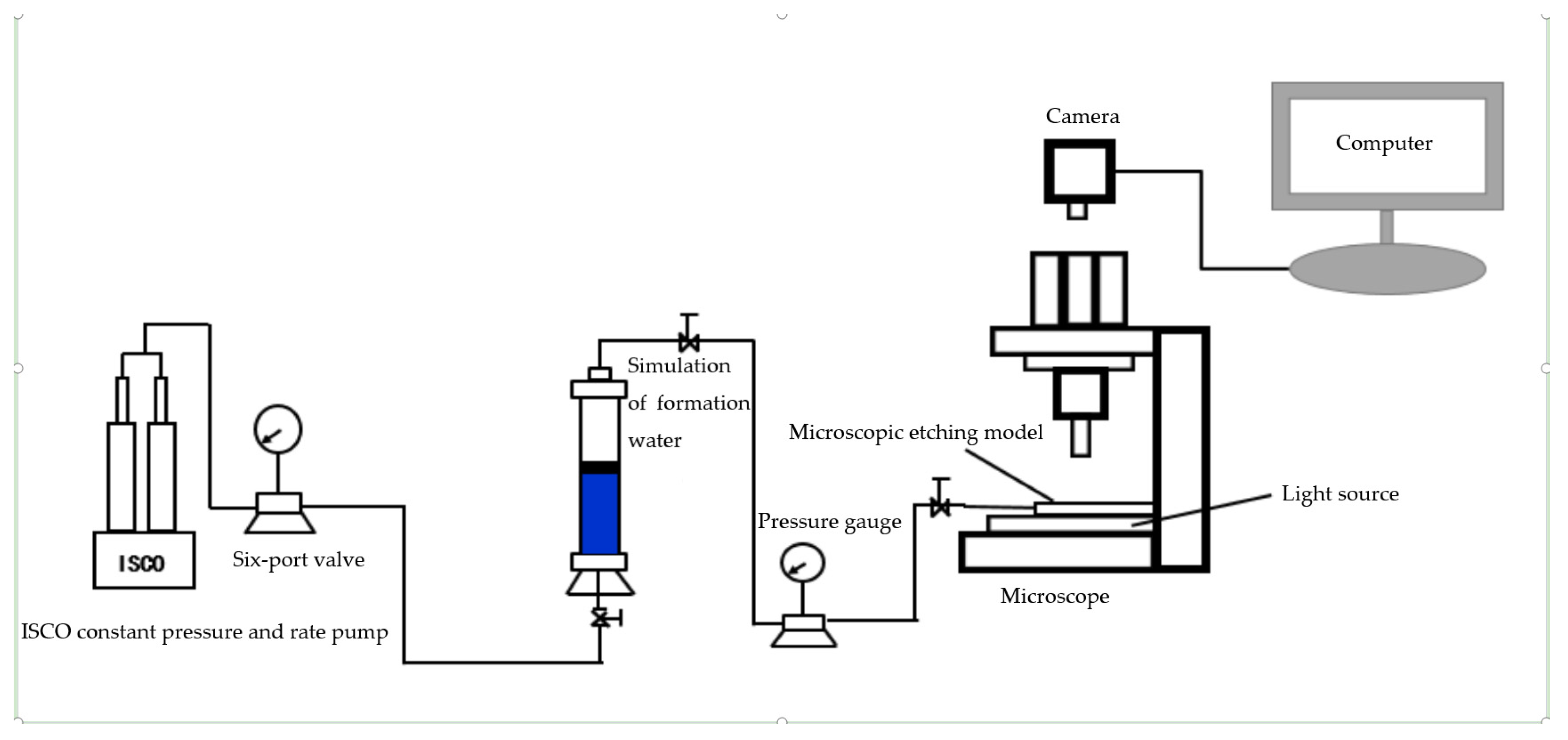
3.1. Visual Seepage Experiment Based on Microscopic Etching Model

Based on the characteristics of the pore structure of the carbonate thermal reservoir in Xiong’an New Area, laser etching and other methods were applied to produce a rock pore structure on the glass surface that was consistent with that in the study area, and a microscopic etching model with dual media of typical pores and fissures was designed. The microscopic etching model was 4 cm × 4 cm; the pore throat was 50 μm due to process and tracing limitations, and the three fissures were 100 μm, 200 μm, and 300 μm, as shown in Figure 2.
This paper studied the impact of the fissure azimuth and injection rate on the seepage patterns and swept areas of geothermal reinjection by establishing a microscopic visual simulation model using a laser. Moreover, a 1% methylene blue solution was prepared as a tracer for the seepage of injected water to facilitate the analysis of the seepage patterns and swept areas. Figure 3 shows the flowchart of the microscopic seepage experiment.

3.2. Seepage Experiment on Physical Cemented Plate Model of Carbonate Fissures

The physical cemented plate model of carbonate fissures is shown in Figure 4. Its size was 30 cm × 30 cm × 3 cm, cemented and pressed using dolomite and epoxy resin. The matrix permeability of the core was 20 mD, and the pore throat was 50 μm. Three fissures and two karst caves were designed to simulate the characteristics of the carbonate thermal reservoir. The karst cave was achieved by suppressing the salt grains. The width of the three fissures was 100 μm, 200 μm, and 300 μm, and the lengths were 30 cm, 20 cm, and 20 cm. The fracture width was adjusted by the thickness of the gaskets, which were drilled with different small holes to ensure seepage between the fractures and the matrix. The physical cemented plate model was vacuumed into saturated formation water. And the model was placed at the set carbonate thermal storage temperature and heated to the target reservoir temperature (65 °C). A total of 36 temperature probes were embedded in advance to monitor the changing distribution of the temperature field in real time. Based on the physical cemented plate model of the carbonate fissures with dual media, the injection and production wells were arranged differently to simulate the influence of the fracture development azimuth and well patterns on the temperature field variation during the seepage of injected water for the development adjustment. The impact of the well arrangements on the seepage patterns of the injected water with different injection–production ratios was researched using the microscopic models of various well systems. The specific well patterns are shown in Table 1.

3.3. Numerical Modeling

Based on the fracture seepage patterns concluded from the visual seepage experiment based on the microscopic etching model and the seepage experiment on the physical cemented plate model of carbonate fissures, a reasonable numerical simulation parameter system was established. According to the geothermal geological characteristics of Xiong’an New Area, the upper Proterozoic Jx and Ch thermal reservoirs were selected. According to the lithological characteristics of each layer, the material properties of the material model and mechanical model were defined, the boundary conditions were set, and the mechanical coupling under the finite element grid calculation was carried out. The material model was constructed according to the Young’s modulus, Poisson’s ratio, density, bio-ratio coefficient, and the thermal expansion coefficient of the limestone in Xiong’an New Area. The mechanical model was constructed according to the mechanical properties of the reservoir, overlying rock, underlying rock, and surrounding rock. Digitization was conducted according to the location and depth of the faults in the structural map of Xiong’an New Area. Large-scale fracture modeling was accomplished by defining the stiffness of the rock and fracture. According to the fracture morphology, fracture orientation, and fracture physical parameters, the fracture density distribution characteristics, angle rotation, random seed number, and equivalent algorithm were selected to control the fracture model. Then, a numeral model of Xiong’an New Area was established using Petrel and tNavigator software (Figure 5). This study took the numerical model of the resettlement area of Xiong’an New Area as an example. The model had an effective grid of 340,000, involving 52 production wells. The Rongcheng fault, which was mainly considered, is located at the boundary of Niutuo Town bulge and Rongcheng bulge, about 30 km long, close to NNE, with an inclination of about 45°; the fault amplitude is 3000 m and the horizontal distance is 1000–3000 m. The uplifted side is Minghua Town group, directly covering the middle and upper proterozoic realms, and the downthrown side is the ancient system. The study area was mainly located in the uplifted side of the fault area.
A.
Pressure-field finite element
Based on the mass conservation equation, we supposed that the flow of geothermal water in an anisotropic aquifer satisfied Darcy’s law. Then, we derived the mass conservation equation for the geothermal water system. The problem of solving the geothermal water pressure field can be described as:
S 0 1 + ρ r h t + ϕ ρ 0 ρ T T t x i K i j 0 1 + ρ r μ r h + ρ r z = ρ Q ρ 0 Q h ( x , y , z , t ) | t = 0 = h 0                         ( x , y , z ) Ω h ( x , y , z , t ) | Γ 1 = h 1                         t > 0 , ( x , y , z ) Γ 1 q n ( x , y , z , t ) | Γ 2 = K i j 0 μ r h + ρ r z n i               t > 0 , ( x , y , z ) Γ 2
where ρ is the groundwater density; ρr is thedensity variation rate of geothermal water; Φ is the effective porosity; t is time; ρQ is the density of the source–sink terms; Q is the source sink item; μr is the coefficient of relative dynamic viscosity, Kij is the permeability, i, j = x, y, z, h is the water level in the reference condition; ρ0 is the density under the reference condition; S0 is the elastic water supply; Γ1 is the first boundary, where a part of the reference pressure is known; Γ2 is the second boundary, which is a given flow boundary; ni is the external normal direction at boundary Γ2; qn is the known function at boundary Γ2, representing the lateral recharge per unit area. The production well or injection well was used as a known point sink or point source. The extracted amount or the injected amount is the q, with negative values for the production well and positive values for the injection well.
B.
Temperature field finite element
For the medium-and low-temperature geothermal water systems, the modes of geothermal water heat transport in porous media were mainly divided into three categories. The first mode was heat transfer through the convection of water. The second mode was heat transfer through water and solid particles in a porous medium. Finally, the heat was transported through the thermomechanical dispersion of the water, according to the transport mode of geothermal water and the conservation of energy. The energy conservation equation in the geothermal water system can be divided into two parts. One part is the energy conservation of the water in the porous media. The other is the energy conservation of solid particles in the porous media. The thermal dynamic equilibrium between the water and solid particles in the thermal reservoir was assumed to be transiently completed. There was no heat source in the aquifer, and the heat flow in the underground hot water system was mainly transported in the way of the convection mode, conduction mode, and thermomechanical dispersion. The temperature field-bound problem can be described:
ϕ ρ C f + 1 ϕ ρ s C s T t + ρ C f q i T x i x i λ i j T x j + ρ Q C Q Q T T Q = 0 T x , y , z , t | t = 0 = T 0                         x , y , z Ω T x , y , z , t | Γ 4 = T 1                         t > 0 , ( x , y , z ) Γ 4 q h x , y , z , t | Γ 5 = λ i j T x j n i                                   t > 0 , ( x , y , z ) Γ 5
λ i j = λ i j c o n d f + λ i j d i s p f + λ i j c o n d s . Where λ i j c o n d f is the thermal-conductivity coefficient of the water, λ i j c o n d s is the thermal-conductivity coefficient of the solid particles, λ i j d i s p f is the thermomechanical dispersion coefficient of the water; ρs is the density of the porous medium; Q is the heat source sink term; TQ is the temperature of the heat source sink item; T0 is the known temperature on the calculated region Ω. Γ4 is the first boundary, where a part of the temperature was known; Γ5 is the second boundary, which was a given flow boundary; qh is the heat flux of the inflow at the boundary Γ5. The production well or injection well was used as a known point sink or point source, and negative values were used for the production well and positive values for the injection well.

4. Result

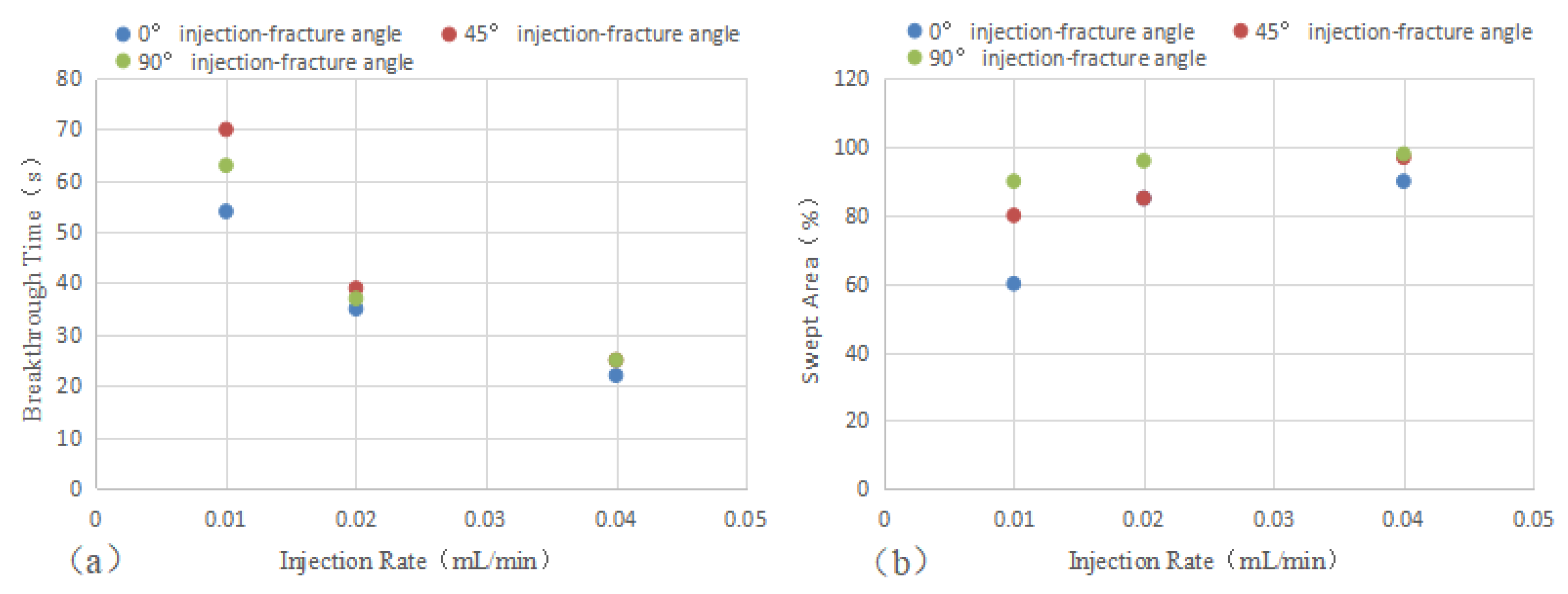
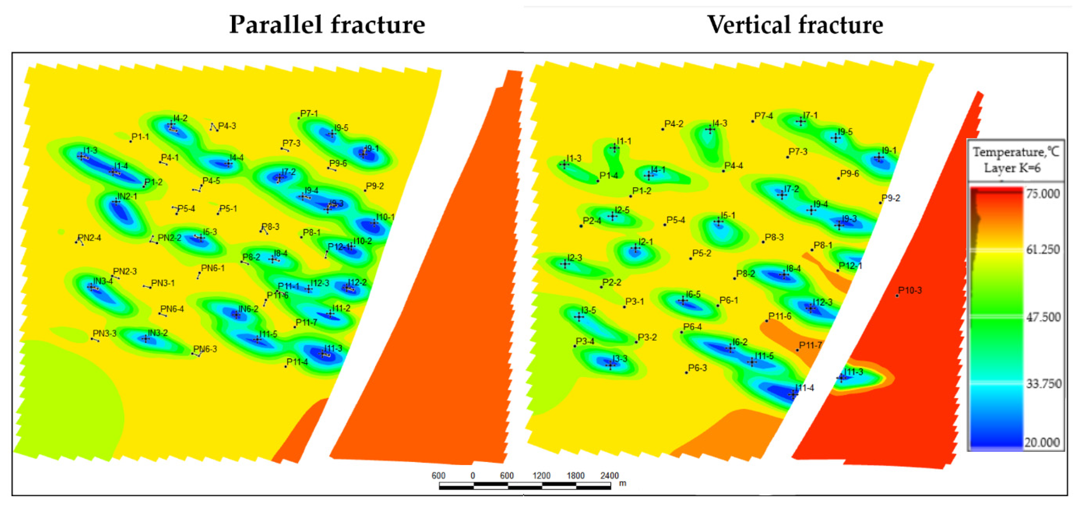
4.1. Macroscopic Spatterns and Distribution Characteristics of Temperature Fields of Injected Water with Different Fracture Azimuths

Recharge methods were simulated to study the macroscopic seepage patterns and distribution characteristics of the temperature fields of the injected water with different fracture azimuths. The visual seepage experiment based on the microscopic etching model studied the impact of the injection rate and injection angle on the flow direction of the injected water to explore the seepage pattern. The experimental results are shown in Table 2 and Table 3 and Figure 6.
As shown in Table 4, the injection rate was negatively correlated to the breakthrough time to a great extent, and significantly correlated to the swept area. Its correlation with the injection rate and breakthrough time was enhanced with a controlled injection angle. The injection angle was correlated with the swept area instead of the breakthrough time, indicating that the injection rate had a more significant impact on the breakthrough time and swept area.
As shown in Table 3 and Figure 6a, the breakthrough time was the longest, or the breakthrough velocity was the highest, with a 45° fracture dip and low injection rate at the same injection angle, followed by that with a 90° fracture dip. The breakthrough time was the shortest with a 0° angle along the fracture direction. However, as the injection rate increased, the gap narrowed. When the injection rate reached 0.04 mL/min, the breakthrough time and swept area in different injection angles tended to become the same. Moreover, the breakthrough time decreased sharply with an increase in the injection rate, indicating that the thermal breakthrough was more likely to occur with a high reinjection rate.
As seen in Figure 6b, the swept area of the injected water was the largest with a 90° fracture dip and low injection rate at the same injection angle, followed by that with a 45° fracture dip. The swept area was the smallest with a 0° angle along the fracture direction, indicating that as the injection-fracture angle increased, the injected water could not break through in the preferential migration passages in the fracture, enlarging the swept area. The weakened water channeling increased the swept area of the injected water. Moreover, the increase slowed with the increases in the injection rate and swept area. Therefore, the heat exchange occurrence in the thermal breakthrough reduced by a higher injection rate exceeded that increased by a larger swept area.

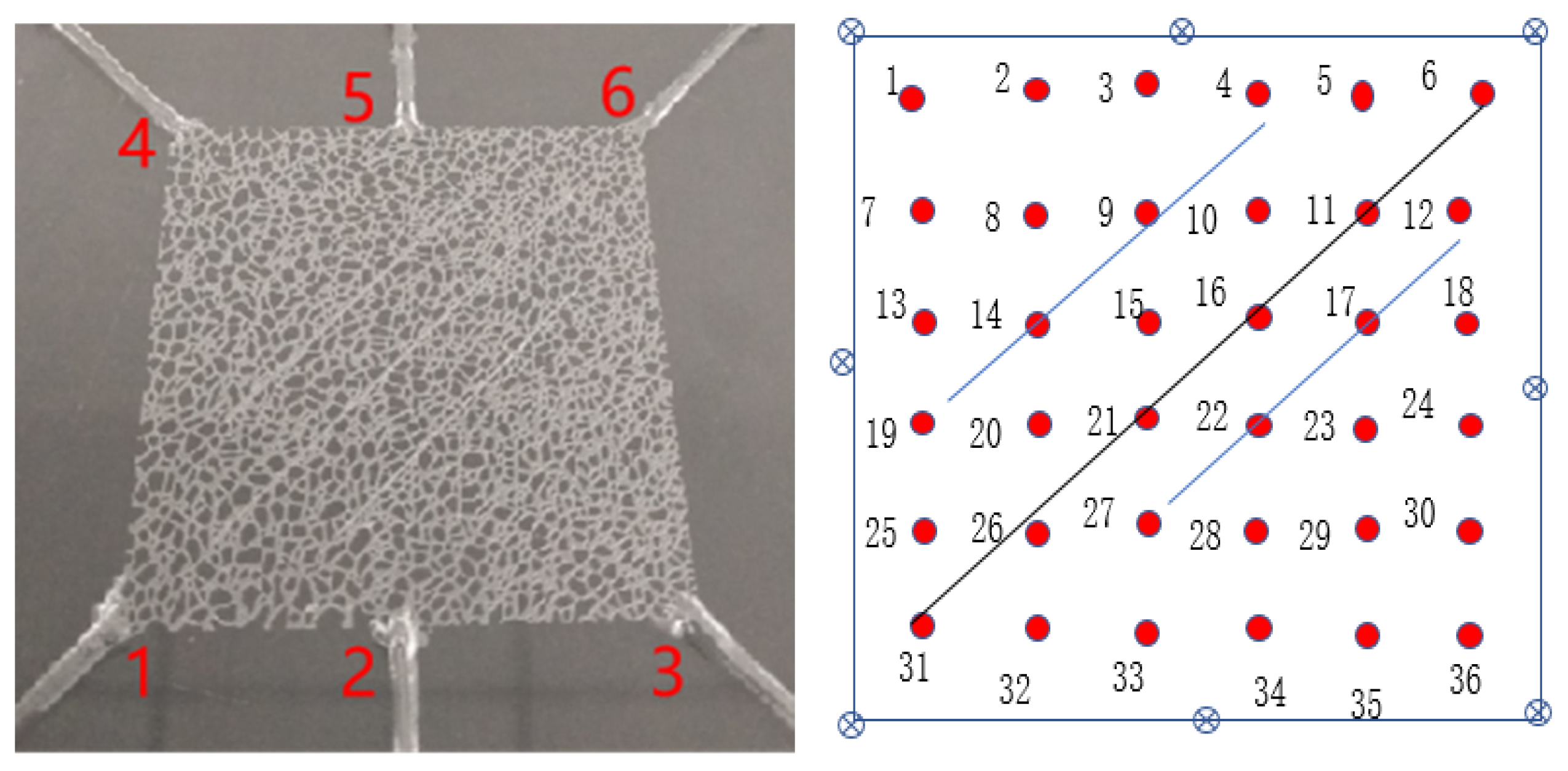
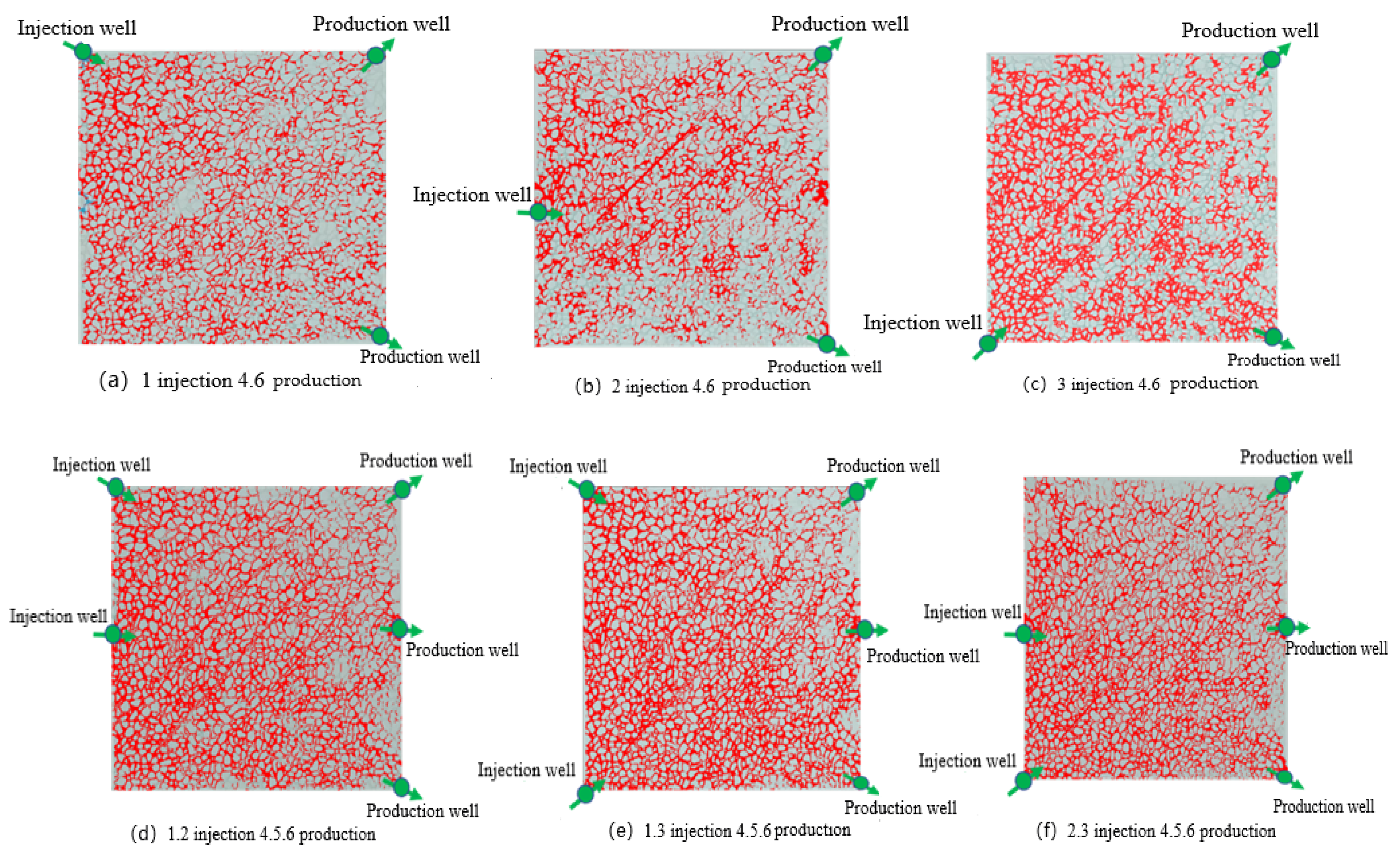
4.2. Study on Seepage Patterns with Different Well Arrangements

The seepage experiment with the physical cemented plate model of carbonate fissures studied the seepage patterns with different well arrangements. The results are shown in Table 4 and Figure 7. For the well pattern of one injector and two producers, the swept area of the injected water in Figure 7b,c was smaller than that in Figure 7a, as the primary seepage routes in (b) and (c) were parallel to the preferential migration passages in the fracture. The strengthened water channeling reduced the swept area of the injected water to a certain extent. For the well pattern of two injectors and three producers, the swept area of the injected water in Figure 7f was smaller than that in Figure 7b,c, and it was almost the same as that in Figure 7d,e. This was because the preferential migration passage allowed the injected water to flow rapidly along it, resulting in a relatively small swept area. Overall, the well pattern of two injectors and three producers was relatively suitable for geothermal reinjection considering the well interference, swept area, and maximum on-site economic benefits. Meanwhile, the maximum injection-fracture angle of “1 and 2 for injection and 4, 5, and 6 for production” was more suitable with the largest swept area.

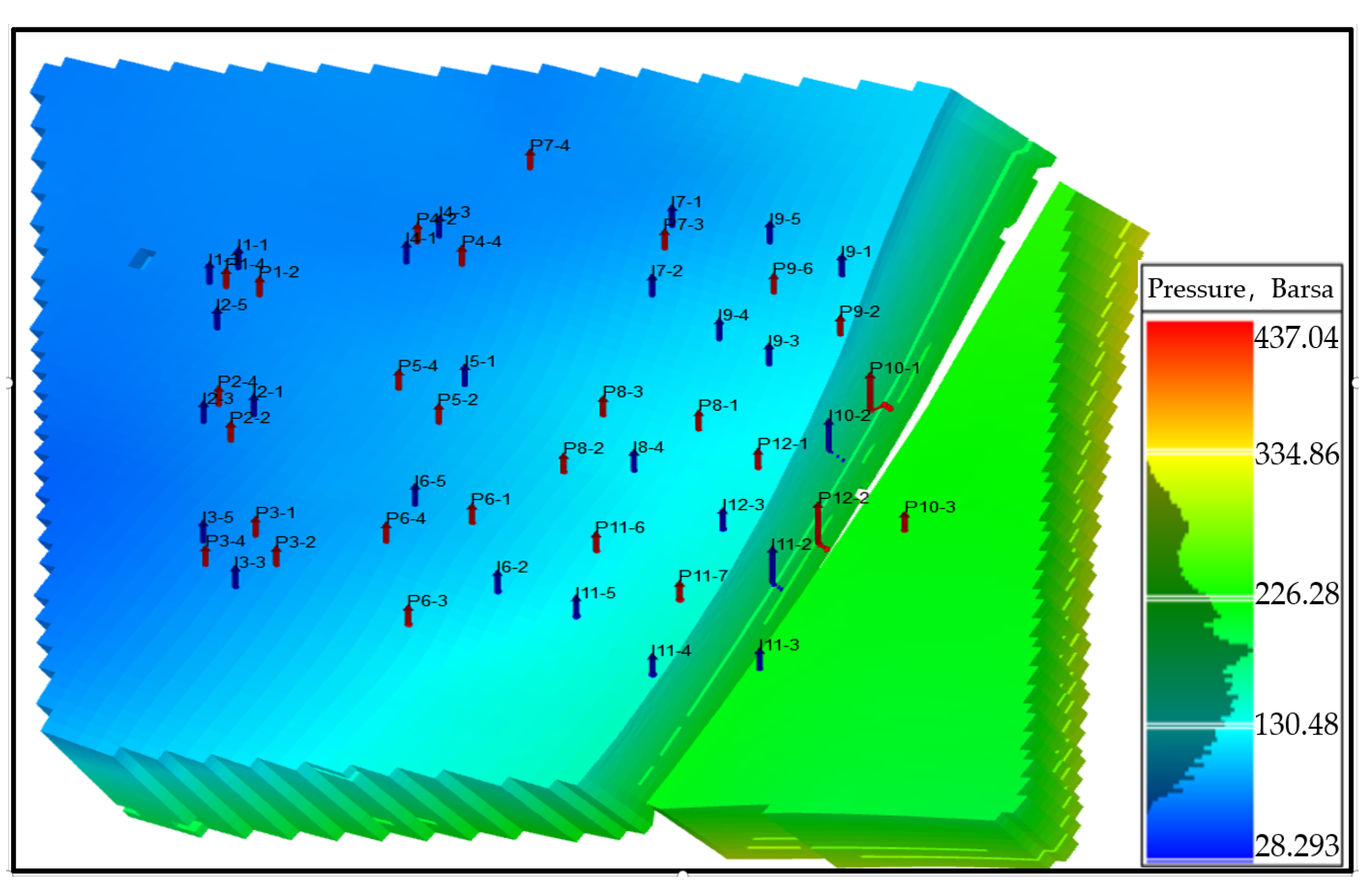
4.3. Modeling of Geothermal Doublet Well Patterns in Xiong’an New Area

The results of the visual seepage experiment with the microscopic etching model and the physical cemented plate model of carbonate fissures showed that the injection rate and angle of the injected water affected the seepage pattern in the fracture. As the well-fracture dip increased, the injected water could not flow through the preferential migration passage, and the weakened water channeling enlarged the swept area. With the same dip, the swept area significantly increased with the higher injection rates. The swept area was the largest and most optimal with a 90° well-fracture dip. Guided by the fracture influence law and the conclusions of the physical model experiments, a numerical model of Xiong County, Rongcheng, and the resettlement area of Xiong’an New Area was built using tNavigator, based on the current development and utilization of the geothermal resources, the production data, and the geothermal doublet well pattern in Xiong’an New Area. The result analysis is as follows.

4.3.1. Demonstration of Relationship between Well Patterns and Fissures

The temperature field variation with two types of well patterns, parallel and vertical fractures, was simulated, as shown in Figure 8. The fractures were mainly perpendicular to the fault distribution; the white-band set in the figure is the fault. The results showed that the injected water broke through faster along the parallel fracture. Therefore, the geothermal doublet well should be arranged in the vertical fracture.

4.3.2. Demonstration of Spacing of Geothermal Doublet Wells

The temperature field variation with different well spacings (200 m, 300 m, 400 m, 600 m) was simulated, as shown in Figure 9. The results showed that a well spacing over 400 m could avoid thermal breakthroughs in the simulated developments. And the 600 m well spacing was too large, which may have affected the recovery of the well capacity. Therefore, it is suggested that the well spacing be over 500 m considering the geological and development factors.

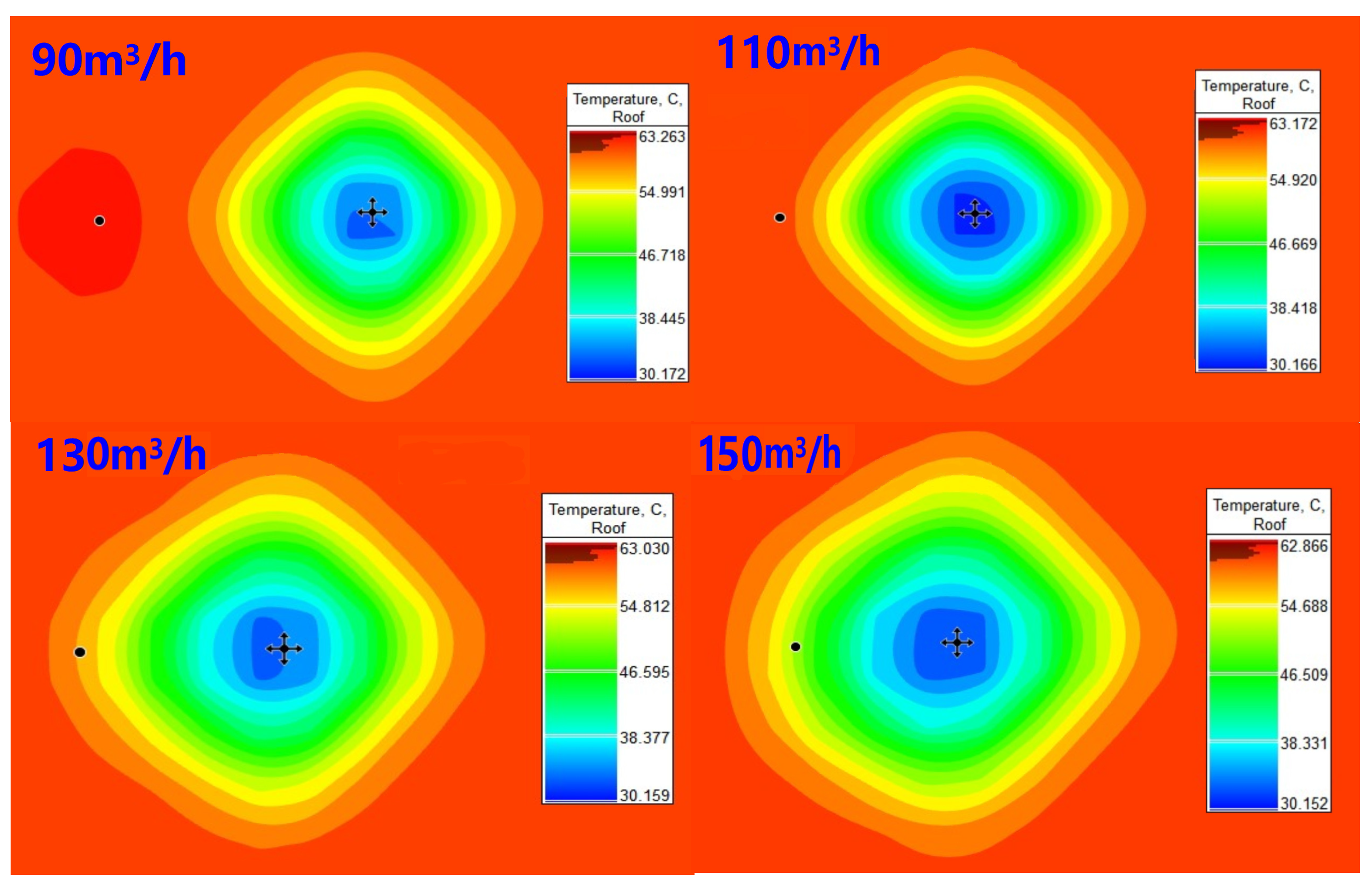
4.3.3. Demonstration of Injection and Production Volumes

The temperature field variation with different injection and production volumes (90 m3/h; 110 m3/h; 130 m3/h; 150 m3/h) were simulated with a well spacing of 500 m (Figure 10). The results showed that thermal breakthroughs would occur when the injection and production volumes exceeded 110 m3/h during the simulated development. Therefore, it is suggested that the injection and production volumes be lower than 110 m3/h.

4.3.4. Feasibility Demonstration of Well Interchangeability

The simulation showed that the water temperature of the second heating season dropped from 63 °C to 48 °C when the injection and production wells were interchanged, as shown in Table 5. It can be concluded that well interchange decreased the water temperature. Therefore, the injection and production wells should not be interchanged in the development process.

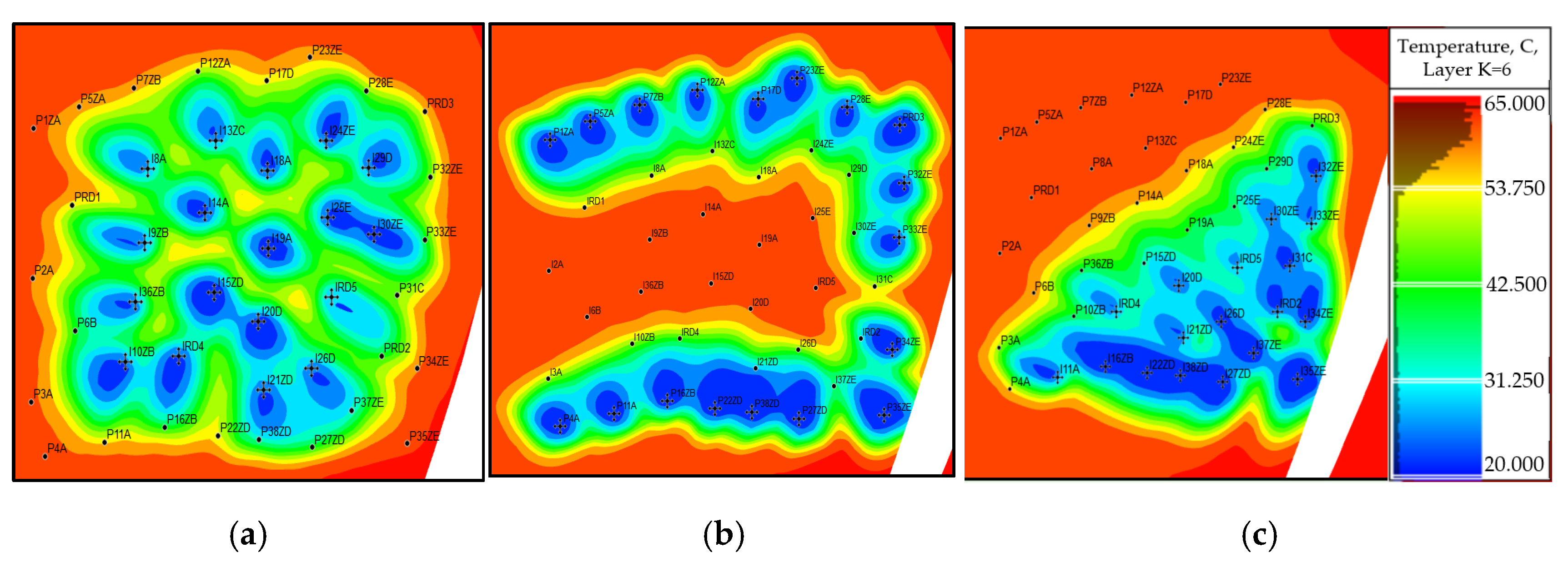
4.3.5. Demonstration of Centralized Geothermal Doublet Well Patterns

The temperature field variation with different injection and production patterns is shown in Figure 11. The simulation revealed that the three centralized patterns were more likely to result in thermal breakthrough in the area close to the injection well during the simulated development. In particular, the thermal breakthrough was the most serious in the “side-by-side centralized injection and production” pattern. The “central production and surrounding injection” pattern had less influence on the thermal breakthrough.

5. Discussion

Hydrothermal geothermal systems require reinjection to maintain formation pressure, avoid production declines caused by pressure drop, and require reasonable well spacing to avoid thermal breakthrough. The seepage process of reinjection geothermal fluid in the reservoir also affects the thermal breakthrough time and exploitation efficiency. Multiple factors influence the seepage of injected water in the thermal reservoir, such as the matrix permeability, porosity, fractures, and other preferential migration passages. When the injected water flows into the thermal reservoir with a preferential migration passage, most of the injected water will flow into the production well along the passage. In fluid heat conduction, the heat of the rocks near the preferential migration passage is rapidly extracted, while that from the rocks in other passages is not. Moreover, if a thermal breakthrough occurs, then the heating effect of the thermal reservoir on the injected water is unclear. When there are no preferential migration passages in the bedrock pores of the thermal reservoir, such as fractures, the injected water will flow and exchange heat in the bedrock pores, with heat conduction as the primary mode of the heat exchange. As there are no preferential migration passages, the fluid sweeps more widely in the thermal reservoir.
Factors such as the well arrangement and temperature of the injected water are essential in the overall design of the reinjection project, and they can prevent the injected water from reaching the production well too quickly and decreasing the temperature there. A smaller well spacing or flow path, such as an open fracture between wells, may result in a “thermal breakthrough”. Few “thermal breakthroughs” caused by geothermal reinjection have been observed worldwide. However, studies have shown that the reinjection of low-temperature cooling water can decrease the thermal storage temperature around the injection well to various degrees. However, it has little impact on the temperature field of the thermal reservoir around its location [30]. Kamila et al. [31] statistically analyzed more than 80 geothermal projects; the spacing of pore-type geothermal doublet wells of the hydrothermal geothermal system is between 0.2 and 6 km. Zhu et al. [32] established a numerical model based on the Guantao Formation in Tianjin and proposed that, considering compensation for the reinjection pressure and the impact of the temperature field, the spacing of pore-type geothermal doublet wells should be no less than 500 m. Wang et al. [33] conducted a reinjection test in the geothermal field in the town of Niubao and concluded that a well spacing of 400 m or less might lead to a rapid temperature decrease in the production well. In contrast, a well spacing of 1500 m is relatively safe. Kong et al. [34] established a numerical model using a carbonate heat reservoir in northern China and proposed that the optimal well spacing is 400 m. Dou et al. [35] carried out a pilot study on the development of the sandstone thermal reservoir of the Guantao Formation in the middle Hebei and suggested that the injection and production rate of a single well be controlled at 50–60 m3/h. As the thermal reservoir has a high-permeability layer at about 1800 m, the hot-well spacing should be at least 400 m. In this paper, it is suggested for the carbonate thermal reservoir in Xiong’an New Area that the optimal well spacing should be more than 200 m, with production and injection volumes lower than 110 m3/h. Moreover, a vertical fracture well is recommended to reduce geothermal breakthroughs.

6. Conclusions

This paper simulated recharge methods by a laser-etched microscopic model of carbonate thermal reservoirs, and it studied the macroscopic seepage patterns and characteristics of the temperature field distribution of injected water with different fracture azimuths in different well patterns. Guided by the fracture influence law and the conclusions of the physical model experiments, numerical models of the resettlement area of Xiong’an New Area were built based on the production data and current geothermal doublet well pattern. Furthermore, this paper proposed an arrangement scheme of geothermal doublet wells and a technical development scheme for the resettlement area of Xiong’an New Area.
(1)
The injection rate and angle of the injected water influenced its seepage pattern in the fracture. The injection rate was negatively correlated to the breakthrough time and positively correlated to the swept area to a great extent. Such correlations were enhanced with a controlled injection angle. The breakthrough time dramatically decreased with the increase in the injection rate, indicating that thermal breakthroughs were more likely to occur with a high reinjection rate. Moreover, as the injection-fracture dip increased, the swept area of the injected water grew larger. The swept area was the largest and most favorable with a 90° dip.
(2)
Well arrangement methods influenced the seepage pattern of the injected water. Considering the well interference, swept area, and maximum on-site economic benefits, the well pattern of two injectors and three producers was relatively suitable for geothermal reinjection, and the maximum injection-fracture angle of “1 and 2 for injection and 4, 5 and 6 for production” was more suitable with the largest swept area.
(3)
The well pattern, well spacing, injection and production volumes, and temperature of the injected water affected the sustainable development and utilization of the geothermal fields. Based on the model demonstration, it is suggested that the resettlement area of Xiong’an New Area arrange its geothermal doublet wells with a spacing of over 500 m, with injection and production volumes lower than 110 m3/h for its geothermal development. Moreover, a vertical fracture well is recommended to reduce geothermal breakthroughs. Injection and production wells should not be interchanged during the development.

Author Contributions

Conceptualization, M.L. and Y.Q.; methodology, Y.Q.; software, Y.Q.; formal analysis, M.L. and Y.Q.; investigation, Y.Q. and L.D.; resources, Y.Q. and L.D.; data curation, Y.Q.; writing—original draft preparation, M.L.; writing—review and editing, M.L., Y.Q. and S.L.; visualization, M.L.; supervision, Y.Q.; project administration, Y.Q.; funding acquisition, Y.Q. All authors have read and agreed to the published version of the manuscript.

Funding

This research received no external funding.

Data Availability Statement

All the data have been presented in the tables and figures.

Conflicts of Interest

The authors declare no conflict of interest.

References

  1. Zhang, W.; Wang, G.L.; Liu, F.; Xing, L.X.; Li, M. Characteristics of geothermal resources in sedimentary basins. Geol. China 2019, 46, 255–268. (In Chinese) [Google Scholar]
  2. Wang, G.L.; Lin, W.J. Main hydro-geothermal systems and their genetic models in China. Acta Geol. Sin. 2020, 94, 1923–1937. (In Chinese) [Google Scholar]
  3. Zhang, D.Z.; Liu, Z.G.; Lu, H.L. Hebei Geothermal; Geology Press: Beijing, China, 2013. (In Chinese) [Google Scholar]
  4. Wang, G.L.; Gao, J.; Zhang, B.J.; Xing, Y.F.; Zhang, W.; Ma, F. Study on the thermal storage characteristics of the Wumishan Formation and huge capacity geothermal well parameters in the Gaoyang low uplift area of Xiong’an New Area. Acta Geol. Sin. 2020, 94, 1970–1980. (In Chinese) [Google Scholar]
  5. Ma, F.; Wang, G.G.L.; Zhang, W.; Zhu, X.; Zhang, H.X.; Yue, G.F. Structure of geothermal reservoirs and resource potential in the Rongcheng geothermal field in Xiong’an New Area. Acta Geol. Sin. 2020, 94, 1981–1990. (In Chinese) [Google Scholar]
  6. Kennedy, B.M.; Pruess, K.; Lippmann, M.J.; Ernest, L.M.; Rose, P.E.; Adams, M.; Roberston, T.A.; Moller, N.; Weare, J.; Clutter, T.; et al. A History of Geothermal Energy Research and Development in the United States on 1976–2006; Office of Energy Efficiency and Renewable Energy (EERE): Washington, DC, USA, 2010.
  7. Cappetti, G.; Parisi, L.; Ridolfi, A.; Stefani, G. Fifteen years of reinjection in the Larderello-Valle Secolo area: Analysis of the production data. In Proceedings of the World Geothermal Congress, Florence, Italy, 18–31 May 1995. [Google Scholar]
  8. Ungemach, P.; Antics, M. Sustainable geothermal reservoir management practice. In Proceedings of the Geothermal Resources Council Annual Meeting 2009, Reno, NV, USA, 4–7 October 2009. [Google Scholar]
  9. Diazr, A.R.; Kaya, E.; Zarrouk, S.J. Reinjection in geothermal fields−a worldwide review update. Renew. Sustain. Energy Rev. 2016, 53, 105–162. [Google Scholar]
  10. Zarrouk, S.; Kaya, E.; O’Sullivan, M.J. A review of worldwide experience of reinjection in geothermal fields. In Proceedings of the 28th NZ Geothermal Workshop, Auckland, New Zealand, 15–17 November 2006. [Google Scholar]
  11. Matthiasdottir, K.V.; Albertsson, A.; Sigurð-Sson, O. Tracer tests at reykjanes geothermal field, Iceland. In Proceedings of the World Geothermal Congress, Melbourne, Australia, 16–24 April 2015. [Google Scholar]
  12. Cheng, W.Q.; Liu, J.L.; Chen, H.B. Simulation research on reinjection temperature field of geothermal doublet well. Glob. Geol. 2011, 30, 486–492. (In Chinese) [Google Scholar]
  13. Feng, S.T.; Wang, C.M.; Yang, Y.B.; Song, W.H.; Liu, S.; Zhao, J.C. Impact assessment of reinjection on sandstone geothermal reservoir:a case study of Northwest Shandong depression. Acta Geol. Sin. 2019, 93, 158–167. (In Chinese) [Google Scholar]
  14. Ruan, C.X. A Study of Reinjection of Geothermal Resources in the Geothermal Reservoir of the Wumishan Group in Tianjin; China University of Geosciences: Beijing, China, 2018. (In Chinese) [Google Scholar]
  15. Nam, Y.; Ooka, R. Numerical simulation of ground heat and water transfer for groundwater heat pump system based on real-scale experiment. Energy Build. 2010, 42, 69–75. [Google Scholar] [CrossRef]
  16. Freedman, V.L.; Waichler, S.R.; Mackley, R.D.; Horner, J.A. Assessing the thermal environmental impacts of angroundwater heat pump in southeastern WashingtonState. Geothermics 2012, 42, 65–77. [Google Scholar] [CrossRef]
  17. Ilyushin, Y.V.; Asadulagi, M.-A.M. Development of a Distributed Control System for the Hydrodynamic Processes of Aquifers, Taking into Account Stochastic Disturbing Factors. Water 2023, 15, 770. [Google Scholar] [CrossRef]
  18. Anastasiya, A.M.; Irina, V.M.; Dmitrii, A.K.; Igor, N.K. The Modeling of Mineral Water Fields Data Structure. In Proceedings of the 2021 IEEE Conference of Russian Young Researchers in Electrical and Electronic Engineering (ElConRus), Moscow, Russia, 26–29 January 2021. [Google Scholar]
  19. Mahmoodpour, S.; Singh, M.; Bär, K.; Sass, I. Thermo-hydro-mechanical modeling of an enhanced geothermal system in a fractured reservoir using carbon dioxide as heat transmission fluid- A sensitivity investigation. Energy 2022, 254, 124266. [Google Scholar] [CrossRef]
  20. Wei, K.; Nie, F.J.; Guo, Y.; Li, Y.F.; Wang, X.Y. Study on the effect of interwell fracture on geothermal recharge. Renew. Energy Resour. 2020, 38, 24–28. (In Chinese) [Google Scholar]
  21. Qu, Z.Q.; Zhang, W.; Guo, T.k.; Sun, J.; Gong, F.C.; Tian, Y.; Li, X.L. Numerical simulation of heat mining performance of hotdry rocks with fracture network based on a local thermal non-equilibrium model. J. China Univ. Pet. (Ed. Nat. Sci.) 2019, 43, 90–98. (In Chinese) [Google Scholar]
  22. Du, L.; Tang, G.; Zhan, H.Y. Seepage and heat transfer characteristics of acid corroded fractures in carbonate rock. Sci. Technol. Eng. 2021, 21, 14333–14344. (In Chinese) [Google Scholar]
  23. Fan, D.Y.; Sun, H.; Yao, J.; Li, H.F.; Yan, X.; Zhang, K.; Zhang, L. Parametric Analysis of Different Injection and Production Well Pattern in Enhanced Geothermal System. J. Jilin Univ. (Earth Sci. Ed.) 2019, 49, 797–806. (In Chinese) [Google Scholar]
  24. Wang, G.L.; Lin, W.J.; Liu, F.; Gan, H.N.; Wang, S.Q.; Yue, G.F.; Long, X.T.; Liu, Y.G. Theory and survey practice of deep heat accumulation in geothermal system and exploration practice. Acta Geologica Sinica 2023, 97, 639–660. (In Chinese) [Google Scholar]
  25. Li, M.; Xing, L.X.; Wang, G.L.; Zhang, W.; Zhao, J.Y. Distribution Characteristics of Fluorine in Deep Geothermal Water and Its Risk Assessment and Suggestions for Utilization in JIZHONG Depression. Geology in China. Available online: https://kns.cnki.net/kcms/detail/11.1167.P.20221012.1750.002.html (accessed on 13 October 2022).
  26. Dai, M.G.; Ma, P.P.; Lei, H.F.; Hu, J.G.; Guo, X.F.; Zhang, J.Y.; Bao, Z.G. Distribution characteristics and favorable targets of karst geothermal reservoir of Wumishan Formation in Xiong’an New Area. Chin. J. Geol. (Sci. Geol. Sin.) 2020, 55, 487–505. (In Chinese) [Google Scholar]
  27. Tang, B.N.; Zhu, C.Q.; Qiu, N.S.; Cui, Y.; Guo, S.S.; Chen, C. Characteristics of the karst thermal reservoir in the Wumishan Formation in the Xiong’an New Area. Acta Geol. Sin. 2020, 94, 2002–2012. (In Chinese) [Google Scholar]
  28. Wang, S.Q.; Zhang, B.J.; Li, Y.Y.; Xing, Y.F.; Yuan, W.Z.; Li, J.; Gao, J.; Zhao, T. Heat accumulation mechanism of deep ancient buried hill in the northeast of Gaoyang geothermal field, Xiong’an New Area. Bull. Geol. Sci. Technol. 2021, 40, 12–21. (In Chinese) [Google Scholar]
  29. Zhang, H.; Wang, G.; Zhang, W.; Ma, F.; Zhu, X.; Yue, G.; Yu, M. Characteristics of the Rongcheng Bulge geothermal field and the evolution of geothermal fluids, Xiong’an New Area, China. Water 2022, 14, 2468. (In Chinese) [Google Scholar] [CrossRef]
  30. Cao, Q.; Fang, C.H.; Li, Y.; Wang, H.X.; Fang, Q.; Shi, X.Y. Development status of geothermal reinjection at home and abroad and its enlightenment. Oil Drill. Prod. Technol. 2021, 43, 203–211. (In Chinese) [Google Scholar]
  31. Kamila, Z.; Kaya, E.; Zarrouk, S.J. Reinjection in geothermal fields: An updated worldwide review 2020. Geothermics 2021, 89, 101970. [Google Scholar] [CrossRef]
  32. Zhu, J.L.; Zhu, X.M.; Lei, H.Y. Analysis of impact of pressure compensation between geothermal wells on reinjection effeciency. Acta Energ. Sol. Sin. 2012, 33, 56–62. (In Chinese) [Google Scholar]
  33. Wang, S.F.; Liu, J.R.; Lin, P.; Li, H.K.; Yin, M.; Pang, J.M.; Sun, C.X.; Gao, X.R. A study of reinjection experiment and tracer test in a karst geothermal reservoir. Hydrogeol. Eng. Geol. 2013, 40, 129–133. (In Chinese) [Google Scholar]
  34. Kong, Y.L.; Pang, Z.H.; Shao, H.B.; Kolditz, O. Optimization of well-doublet placement in geothermal reservoirs using numerical simulation and economic analysis. Environ. Earth Sci. 2017, 76, 118. [Google Scholar] [CrossRef]
  35. Dou, H.P.; Chen, X.H.; Zhou, Q.C.; Zhuang, W.J.; Lian, Z.H. Simulation study on thermal recovery and thermal recoverable under balanced exploitation condition:A case study of Guantao sandstone geothermal reservoir in Renqiu area. Geotech. Investig. Surv. 2021, 49, 39–45. (In Chinese) [Google Scholar]
Figure 2. (a) Microscopic etching model and (b) the physical diagram.
Water 15 02683 g002
Figure 3. Flowchart of microscopic seepage experiment.
Water 15 02683 g003
Figure 4. Design of physical cemented plate model of carbonate fissures.
Water 15 02683 g004
Figure 5. Three-dimensional numerical simulation of original pressure in geothermal field of resettlement area of Xiong’an New Area.
Water 15 02683 g005
Figure 6. (a) Relation graph of injection velocity versus breakthrough time and (b) swept area.
Water 15 02683 g006
Figure 7. Experimental results of different well patterns.
Water 15 02683 g007
Figure 8. Temperature field distribution with different well-fracture dips.
Water 15 02683 g008
Figure 9. Temperature field distribution with different well spacing.
Water 15 02683 g009
Figure 10. Temperature field distribution with different injection and production volumes.
Water 15 02683 g010
Figure 11. Thermal breakthroughs in different injection and production patterns. (a) Surrounding production and central injection. (b) Central production and surrounding injection. (c) Side-by-side centralized injection and production.
Water 15 02683 g011
Table 1. Design of microscopic models for different well patterns.
Well PatternInjection–Production RatioInjection Rate (mL/min)Well Placement
1 Injector and 2 Producers2:10.02Injector:1 and Producers:4.6
Injector:2 and Producers:4.6
Injector:3 and Producers:4.6
2 Injector and 3 Producers1:5:10.015Injectors:1.2 and Producers:4.5.6
Injectors: 1.3 and Producers:4.5.6
Injectors:2.3 and Producers:4.5.6
Table 2. Leading-edge breakthrough time and breakthrough velocity with different injection angles and injection rates.
Injection Angle
(°)
Injection Rate (mL/min)Breakthrough Time
(s)
Breakthrough Velocity
(m/d)
Injection Time
(s)
Swept Area (%)
00.01541.5087460
00.02352.3274985
00.04223.7036290
450.01700.8239580
450.02391.4776585
450.04252.3045197
900.01631.29313090
900.02372.2024096
900.04253.2585698
Table 3. Correlation study on injection and seepage variables.
Correlation
Dependent VariableControl VariableBreakthrough Time
(s)
Breakthrough Velocity
(m/d)
Injection Time
(s)
Swept Area
(%)
Injection RateN/A−0.9030.867−0.570.64
Injection Angle (°)−0.9090.874−0.5840.802
Injection AngleN/A0.116−0.1210.2120.602
Injection Rate0.27−0.2430.2580.783
Table 4. Statistics of microscopic well arrangement models and experimental results of different well patterns.
Well PatternInjection-Production RatioInjection Rate (mL/min)Injection Angle (°)Well LocationSwept Area (%)
One injectors and two producers2:10.0290Injector:1 and Producers:4.675.68
45Injector:2 and Producers:4.659.62
0Injector:3 and Producers:4.665.7
Two injectors and three producers1:5:10.0151:90;
2:45
Injectors:1.2 and Producers:4.5.692.21
1:90;
3:0
Injectors: 1.3 and Producers:4.5.692
2:45;
3:0
Injectors:2.3 and Producers:4.5.686.45
Table 5. Water temperature variation with interchanged wells.
Well No.Test Water Temperature
(°C)
Recharge Temperature
(°C)
Production Temperature (°C)Temperature Difference
(°C)
Boao1#563549−7
Jintai1#513548−3
Zhongjin1#513549−2
Disclaimer/Publisher’s Note: The statements, opinions and data contained in all publications are solely those of the individual author(s) and contributor(s) and not of MDPI and/or the editor(s). MDPI and/or the editor(s) disclaim responsibility for any injury to people or property resulting from any ideas, methods, instructions or products referred to in the content.

