Article

Stability Study of a Double-Row Steel Sheet Pile Cofferdam Structure on Soft Ground

1
Yellow River Laboratory, Zhengzhou University, Zhengzhou 450001, China
2
Geotechnical Engineering Research Institute, Guangdong Research Institute of Water Resources and Hydropower, Guangzhou 510610, China
*
Author to whom correspondence should be addressed.
Water 2023, 15(14), 2643; https://doi.org/10.3390/w15142643
Submission received: 27 April 2023 / Revised: 10 July 2023 / Accepted: 16 July 2023 / Published: 20 July 2023

Abstract

:
The stability of a double-row steel sheet pile cofferdam structure under soft ground conditions was investigated in this study, using the temporary cofferdam of the Shenzhen–Zhongshan cross-river channel as the engineering background. The stability of the cofferdam design solution was calculated with a model that incorporates factors such as the coordination of independent pile top displacement, as well as the m-value for backfilled sand and the thrown rock body. The internal force and displacement results of the cofferdam under different working conditions are obtained. And the entire construction process was analyzed using the finite element method. The results indicate that the overall stability and overturning stability of the cofferdam satisfy relevant safety requirements, with minimum safety factors of 1.744 and 1.400, respectively. The maximum displacement of the inner and outer steel sheet piles is 34 mm, the maximum bending moment is 249.30 kN·m, and the maximum shear force is 266.66 kN. The displacements of sheet piles were within an acceptable range, and the internal forces remained below the load capacity of the selected sheet pile type for the design. Based on these findings, the cofferdam structure can be considered safe and satisfying the specified requirements. This work may have instructive value for cofferdam design and construction.

1. Introduction

Steel sheet piles have a rich history and have undergone significant development in Europe and Japan since their introduction in the early 20th century. They have become widely utilized in various construction applications, including cofferdams, foundation support in docks, wharves, bridges, immersed tube tunnels, and other projects. Steel sheet piles offer numerous advantages such as high quality, simple construction, durability, and the ability to reduce spatial requirements for construction tasks [1,2]. They are extensively utilized in water conservancy, transportation, municipal, harbor, and navigation projects. In soft soil areas, the double-row steel sheet pile cofferdam structure is particularly favored due to its excellent structural stability, strong resistance to deformation and seepage, and adaptability to engineering challenges [3]. Therefore, it is widely adopted in soft-ground foundation projects.
Scholars have conducted valuable research on the practical applications of double-row steel sheet piles, yielding significant findings. Hou et al. [4] conducted on-site monitoring of a double-row sheet pile cofferdam for a large wharf project in Shanghai, studying its deformation characteristics under construction conditions. Zhu et al. [5] conducted a reliability analysis of double-row steel sheet piles using the Bayesian approach, effectively integrating statistical and field survey data. Mitobe et al. [6] conducted flume model tests on embankment reinforcement using single and double rows of sheet piles to prevent tsunami overflow, observing better performance with double rows of sheet piles. Shen et al. [7] investigated the effects of different lengths of double-row pile support through model tests to find that structural stability was less affected by the appropriate shortening of the pile’s length on the soil-accommodating side. Khan et al. [8] established a centrifugal test model for a double-row sheet pile cofferdam and found that multi-layer tie rods significantly enhanced its stability.
There have been many other valuable contributions to the literature. Zhou et al. [9] found that the displacement of the pile on the back soil side was greater than that of the pile on the facing soil side through small-scale model tests. Sawaguchi et al. [10] simplified the double-row pile structure to a stable frame structure and derived pile displacement curves under different loading conditions. Buhan et al. [11] used the limit equilibrium design theory to calculate the load limit on a cofferdam, considering the weir core fill and sheet piles on both sides as an elastic continuous medium and shell, while also analyzing the deformation based on different boundary conditions. Banerjee et al. [12] analyzed the effect of steady-state seepage on a double-row sheet pile cofferdam structure by adding a seepage safety factor to the theoretical calculations. Lei et al. [13] determined that the damage patterns of slopes reinforced by single and double rows of stabilizing piles differ based on the distribution of potential sliding surfaces, bending moments, and thrusts. Li et al. [14] proposed a simplified analytical model to derive the required resistance of a double-row pile at different rotational angle positions, combining the kinematic approach of limit analysis with the strength discounting technique. Zhang et al. [15] confirmed the feasibility of monitoring the strain of double-row steel pipe piles during foundation excavation through field tests with strain gauges. Zhou et al. [16] reviewed and evaluated the force deformation and earth pressure of double-row pile piles, summarizing current research problems and shortcomings. In a large-scale physical model test based on a deep foundation pit project in Changchun City, Zhou et al. [9] calculated the strain and displacement of double-row piles and soil pressure, finding greater strain and displacement in the front-row piles compared to the rear-row piles. Lefas et al. [17] developed a simplified two-dimensional (2D) model to analyze the steel sheet pile cofferdam structure and investigated its force deformation characteristics during construction according to a calculation program they developed. Byfield et al. [18] conducted experiments and analyses on the calculated deformation of steel plates, providing valuable insights for understanding the forces and pile-soil interaction mechanisms of steel sheet piles.
With advancements in computer technology, numerous scholars have employed numerical analysis methods to investigate the stability of cofferdam structures [19]. Gui et al. [20] analyzed a failed double-row steel sheet pile cofferdam using finite element software and identified low tie weld strength as the cause of damage to the structure. Zhao [21] conducted numerical simulations to analyze the influence of various parameters of double-row steel sheet piles on cofferdam performance, emphasizing the importance of filling materials within the double-row steel pipe pile cofferdam. Xue et al. [22] performed stability analysis on a pile wall frame structure cofferdam through engineering tests and 3D finite element numerical simulation, then proposed a design method based on the limit equilibrium approach. Monika et al. [23] investigated the cofferdam of the main central column foundation of an asymmetric bridge using numerical simulation based on the finite element method with Plaxis geotechnical software. Fujiwara et al. [24] examined the dynamic behavior of a structure with partition walls perpendicular to sheet piles under seismic action through shaking table tests and 2D numerical simulations. Wang et al. [25] used FLAC 3DV6.0 software to numerically simulate the excavation process of steep reinforced riverbank slopes in an effort to predict long-term slope deformation. Xu et al. [26] developed a numerical solution based on the power-law nonlinear damage criterion and the upper bound theorem of limit analysis, deriving the shape of the cofferdam collapse block and landslide thrust under the effects of long-term water waves and residual pore pressure. Hui et al. [27] established a Plaxis 3D finite element model to investigate the relationship between the depth of soil reinforcement between double rows of sheet piles and internal force displacement. Chen et al. [28] studied the hydrodynamic response and seabed response around a dumbbell weir under combined wave and current loads, considering the wave-current interactions. Hu et al. [29] integrated saturated–unsaturated seepage theory and the intensity discounting method into a finite element system to analyze the effects of water level fluctuations on the instability and seepage damage of a landfill weir. Ti et al. [30] evaluated the stochastic wave pressure of a construction cofferdam for a bridge under the action of a tropical cyclone in terms of the pressure spectrum, pressure spectrum characteristics, transfer function, and maximum wave pressure. Wang et al. [31] developed a prediction model for short- and medium-term water levels, enabling dynamic adjustment and adaptation to the actual needs of sheet pile cofferdam construction. Although the above studies have analyzed the structural stability of cofferdams and the safety of the construction process, there is limited research on the structural stability of cofferdams in soft-ground foundations. Additionally, no previous researcher has compared and verified the internal forces and displacements of cofferdam structures using different calculation methods. To this effect, it is difficult to secure accurate predictions of potential adverse conditions during construction, and available techniques for structural reliability analysis are seriously limited.
The safety and stability of double-row steel sheet piles in soft soil areas were analyzed in this study using a Rizheng deep foundation pit and Midas GTS finite element calculation software. The overturning resistance and overall stability of the cofferdam were analyzed, and the minimum internal forces and displacements of the inner and outer steel sheet piles were derived. Additionally, the entire process of cofferdam construction was simulated using the finite element method.

2. Project Overview and Scheme Design

2.1. Project Overview

The Shenzhen–Zhongshan Passage is located approximately 30 km north of Humen Bridge and 38 km south of Hong Kong–Zhuhai–Macau Bridge. To facilitate the construction of a widened bifurcated tunnel, a temporary water retaining structure in the form of a cofferdam will be established in the sea on the Shenzhen side. The cofferdam, classified as grade 4, is designed for the cut and cast structure construction within its boundaries. The cofferdam has a double-row steel sheet pile configuration with a width of 10 m and a total length of approximately 1393.4 m. Once the main tunnel structure is completed and backfilled, the temporary cofferdam above the seabed surface will be dismantled. Figure 1 illustrates the planned layout of the steel sheet pile cofferdam.

2.2. Scheme Design

2.2.1. Profile Design

The construction section of the weir is designed according to marine and surrounding environmental conditions as well as the construction schedule. The cofferdam is divided into two sides: the pit side (inner side) and the waterfront side (outer side). Steel ties 60 mm in diameter are used to connect the inner and outer rows of steel sheet piles, with a spacing and center elevation of 1.5 m. An “L”-shaped retaining wall is installed on the inside of the outer row of steel sheet piles, measuring 2 m in height and 200 mm in thickness. Support walls that are 150 mm thick are placed at intervals of 1.5 m along the axis of the cofferdam. Concrete beams measuring 400 × 500 mm are used to connect the retaining wall and inner row of sheet piles. To prevent scouring of the steel sheet piles, a sand-ribbed soft drain is installed on the waterward side of the cofferdam. A layer of bagged gravel, 25 cm thick, is placed above the soft drain. On the sea side, a rock throwing layer with minimum thickness of 2.0 m is applied, consisting of rocks weighing between 800 and 1500 kg. Blocks weighing 200–300 kg are used for the remaining sides. A counter pressure soil slope is constructed on the backwater side of the cofferdam, which is not protected by molded concrete. Figure 2 shows a typical cross-section of a steel sheet pile cofferdam.

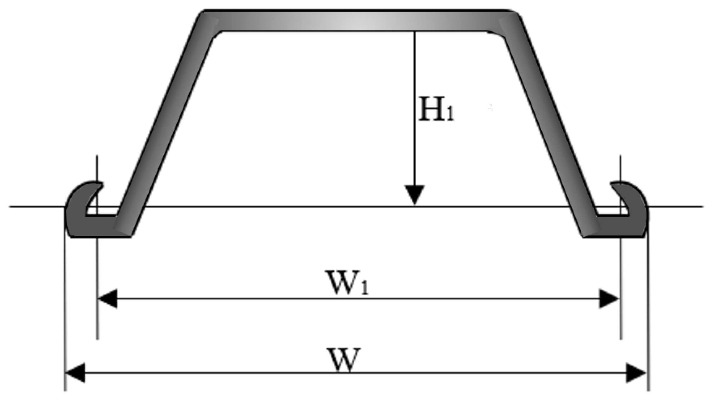
2.2.2. Steel Sheet Pile Section Design and Wave Force Value

The design under analysis has a steel sheet pile model U 750 × 225 × 14.5. The steel type is Q390BZ and Q345B. The flexural load capacity of the structure is 775 kN·m. The steel sheet pile cross-section and characteristics are shown in Figure 3 and Figure 4 and Table 1 and Table 2.
The calculation includes water pressure and wave forces as the primary factors. Water pressure is determined based on each specific working condition, whereas wave crest and wave forces are calculated according to the Harbor Hydrographic Code (JTS 145-2-2013). The design considers extremely unfavorable working conditions, such as encountering waves of the same frequency as the 20-year high tide level. The bed type of the cofferdam project is classified as a low bed, and the wave state is a standing wave. The wave pressure distribution is shown in Figure 5.

3. Structural Stability Analysis

3.1. Overall and Overturning Stability Test

The calculation model was established based on two typical cross sections: K6 + 598 right line and K7 + 030 left line. The overturning and general stability of the cofferdam were calculated using Lizheng Geotechnical Software.

3.1.1. Overall Stability Analysis

The construction period of the temporary cofferdam is expected to span approximately three years. The design considers a flood recurrence period of 5–10 years, and the cofferdam can withstand a level 4 flood. The overall stability calculation requires a safety factor of at least 1.35 for both normal and extraordinary operation conditions. The Swedish circular sliding method is adopted to calculate the overall stability.
min K s , 1 , K s , 1 , , K s , i K s
K s , i = { c j l j + [ ( q j b j + Δ G j ) cos θ j u j l j ] t a n ϕ j } q j b j + Δ G j s i n θ j
where K s is arc sliding stability safety factor; K s , i is the ratio of the anti-slip moment to the sliding moment of the ith arc sliding body; c j is the cohesive force (kPa); ϕ j falls the angle of internal friction (°); b j is the width of the jth soil strip (m); θ j is the angle between the normal and the vertical plane at the midpoint of the slip arc of the jth soil strip (°); l j is slip arc length of the jth soil strip (m); q j is the standard value of the additional distributed load on the jth soil strip (kPa); u j is the water pressure on the slip-arc surface of the jth soil strip (kPa); Δ G j is the self-weight of the jth earth bar (kN).
Two typical cross-sections, the K6 + 598 right line and the K7 + 030 left line, were analyzed for their safety factors under four different working conditions. On the right line of K6 + 598, Condition 1 assumes no precipitation within the cofferdam, and the water level outside the cofferdam sharply drops after its completion. Condition 2 considers the completion of the cofferdam, with the internal water level dropping to 1 m below the surface while the external water level remains at the designed high tide level. Condition 3 assumes no precipitation within the weir, and the external water level rises to the top of the weir’s backfill sand. Condition 4 accounts for the internal water level dropping to 1 m below the berm inside the weir, the external water level at the designed high tide level of the weir, and the backfill sand filled to the top of the weir.
On the left line of K7 + 030, Condition 5 assumes no precipitation within the cofferdam, and the water level outside the cofferdam suddenly drops after its completion. Condition 6 considers the completion of the cofferdam, with the internal water level dropping to 1 m below the surface while the external water level remains at the designed high tide level. Condition 7 assumes no precipitation in the weir and the external water level rises to the top of the weir’s backfill sand. Condition 8 accounts for the internal water level dropping to 1 m below the berm inside the weir, the external water level at the designed high tide level of the weir, and the backfill sand filled to the top of the weir.
The results of the cofferdam stability calculations for comparison are presented in Figure 6.
As shown in Figure 6, the overall stability of this cofferdam was evaluated for eight working conditions in two typical design sections. The minimum safety coefficient is 1.744. All the safety coefficients obtained exceed the safety coefficients specified in the regulations, indicating that the design meets the necessary safety requirements.

3.1.2. Overturning Stability Analysis

The overturning stability of the cofferdam is conducted based on a gravity-type cement soil wall, taking into account the discounted internal friction angle of the finite bagged sand and thrown rock. The discount factor is determined by comparing the required width of the passive zone calculated by the 45-degree rupture angle with the actual width of the passive zone. The calculation of overturning stability follows the formula specified in the Technical Regulations for Construction Pit Support (JGJ120-2012), which state that the safety factor should be at least 1.3. The overturning stability of the gravity-type cement soil wall can be calculated as follows:
E p k a p + G u m B a G E a k a a K o v
where K o v is the overturning safety factor; a a is the vertical distance from the point of combined active earth pressure on the outside of the cement wall to the toe (m), E a k is the standard value of active earth pressure (kN/m); E p k is the passive earth pressure acting on the cement soil wall (kN/m), G is the self-weight of the concrete wall (kN/m); B is the width of the concrete wall’s bottom section (m), u m is the water pressure on the bottom surface of the cement wall (kPa), a p is the vertical distance from the action point of the combined passive earth pressure on the inside of the concrete wall to the toe (m), a G is the horizontal distance from the action point of the combined weight of the cement wall and the water pressure at the bottom of the wall to the toe (m).
The safety coefficient of overturning resistance is calculated for two typical cross-sections, the K6 + 598 right line and K7 + 030 left line, under two sets of respective working conditions. As shown in Figure 7, the overturning stability of this cofferdam is calculated for four working conditions of two design typical sections. The minimum safety factor is 1.4, which meets the specified safety requirements.

3.2. Internal Force and Displacement Analysis

The spacing between the double rows of sheet piles in the cofferdam is 10 m, which is much larger than the width of a single sheet pile. When the sand filling reaches the active limit equilibrium state, the angle between the damaged surface and the sheet pile is considered to be 45° − φ/2. However, at an excavation depth of 7–8 m, the top of the damaged surface is still located between the front and rear rows of the sheet pile, which does not align with the calculation mode for double-row piles. Therefore, the single-row pile mode is considered separately.
The simulation performed in Lizheng deep foundation pit software considers independent pile top displacements for the inner and outer sheet piles, as well as discounts for backfilling sand and the thrown stone body (m-value discounts). To equalize the top displacement of the front and back rows of the pile model, the concentrated pull rod force is progressively adjusted during the calculation. At this stage, the pull rod force is considered more appropriate. This tie force is reapplied to the front pile model to analyze the sheet pile displacements and forces. The material parameters are shown in Table 3 and the calculation model is shown in Figure 8.
The m-value method is an approach that utilizes a vertical plane elastic foundation beam method, where a retaining wall is treated as an elastic beam element and the passive earth pressure inside the pit is simulated using soil springs. This method offers several advantages, including a simplified model, fewer calculation parameters, the ability to simulate distributed excavation, and the ability to capture the relationship between passive soil pressure and displacement. It is widely employed for calculating and analyzing the forces acting on retaining structures during foundation pit excavations.
In the calculation model, the m-values finite rock throwing, coarse sand replacement, and bagged sand are discounted. For reinforced soil, the m-values of bagged sand, backfilled sand inside the weir, sand replacement on the outside of the weir, and thrown rock are discounted by 0.20, 0.12, 0.24, and 0.26, respectively. Calculations were performed in Lizheng deep foundation pit software calculation to validate the design by comparing the displacements of semi-infinite and finite bodies. By calculating the stiffness of both bodies, reduction factors and average values for the same soil layer were obtained as depicted in Figure 9.
Two working conditions were calculated and analyzed. In Condition 1, the inner water level is the design high tide level and the outer water level drops after completion of the cofferdam. The water level reduction is based on a maximum tidal difference of 2.6 m according to hydrological data, and the corresponding wave suction force is taken into account. In Condition 2, the inner water level is lowered to 1 m below the inner apron of the cofferdam and the outer water level remains at the designed high tide level after the cofferdam is built. The corresponding wave thrust is considered.
As an example, consider the K6 + 598 right-line working condition for Condition 1. The inner and outer piles of the cofferdam are inclined outward. The inner and outer sheet piles are treated as independent models. For the inner side piles of the cofferdam, the pit’s inner and outer sides are defined as shown in Figure 10, and a tie rod force pointing out of the cofferdam is applied to the inner piles. The water levels inside and outside the foundation pit are set to high, and the portion above the bagged sand is simplified as a soil layer with c=0, φ=0, and γ=0. The inner bagged sand is considered as a semi-infinite soil layer, and the backfill sand inside the weir is analyzed as reinforced soil in the pit. The excavation depth of the pit is set to 0 m.
As shown in Figure 11, the sheet pile is displaced to the seaward side. The maximum displacement value is −21 mm at the top of the pile, the maximum bending moment value is 150.60 kN·m, and the maximum shear force value is −93.00 kN. The blue line in the figure shows the elastic method and the green line shows the passive earth pressure.
The maximum displacement is 34 mm on the inner and outer sheet piles of the cofferdam, the maximum bending moment is 249.30 kN·m, and the maximum shear force is 266.66 kN. The calculated displacement results are relatively small, and the magnitude of the internal forces satisfies the force requirements for the sheet pile. Therefore, the internal force deformation of the cofferdam meets the original design safety requirements. The internal force deformation results for the two sections of the cofferdam under each working condition are shown in Figure 12.
The calculation results for the single-row steel sheet pile anchor model indicate that the stress on the sheet pile is significantly lower than the allowable stress of the material. This suggests that the material properties of the sheet pile are not fully utilized in the model calculations. Additionally, the horizontal displacement of the steel sheet pile structure is found to be small. This is because the model calculation does not consider the integrity of the double-row sheet pile structure and the interaction between the pile and soil in terms of force and deformation coordination. Therefore, for the initial design stage of the double-row sheet pile cofferdam, it is more appropriate to use the Lizheng deep foundation software. For later stages, however, it is recommended to optimize the design solution using the finite element calculation method.

3.3. Planar Finite Element Calculation of Construction Process

The finite element method has gained popularity due to its ability to incorporate spatial effects and its adaptability, especially for flexible structures in deep soft-ground foundations. The finite element simulation encompasses the entire construction process and relies on geotechnical investigation and ground profiles provided by the design department. To simplify the analysis here, the Mohr–Coulomb method is applied. The finite element calculation model is shown in Figure 13.
The cohesion and friction angle of sludge, clay, and weathered granite were measured in the laboratory by the design department for the purposes of this analysis (Table 4).
K6 + 598 right line and K7 + 030 left line cross-sections were selected for calculation. According to the cofferdam design of this project and the site construction conditions, the main construction steps were determined as shown in Table 5.
Take the left line section of K7 + 030 as an example. The initial horizontal displacement of the steel sheet pile when upon its set-up is not considered. The horizontal displacements of the inner and outer sheet piles at construction step 11 are shown in Figure 14.
The maximum internal force on the cofferdam occurs during construction step 10 (b). At this point, the maximum bending moment of the steel sheet pile inside and outside the cofferdam is 373.6 kN·m and the maximum shear force is 189.7 kN. The displacement of the cofferdam is largest during construction step 11 (a), with the maximum displacement of the steel sheet pile reaching 82 mm. Out of this displacement, 34 mm is attributed to precipitation.
Based on the calculation results of two typical sections under different construction steps and water level working conditions, it is evident that each construction step has limited influence on the internal force deformation of the steel sheet pile. The internal force acting on the steel sheet pile is well below the bearing capacity of the designed steel sheet pile type.

4. Conclusions

This study investigated the overall stability and overturning stability of a double-row steel sheet pile cofferdam in relation to specific projects. The conclusions of this work can be summarized as follows.
(1)
The calculation results show that the minimum safety factor for all working conditions is 1.744, and the minimum safety factor against overturning for all working conditions is 1.40. Both satisfy the code safety requirement of 1.35.
(2)
In the analysis of internal forces and displacements of the cofferdam structure, the calculation results of two typical sections revealed that under the water level drop condition, the maximum displacement on the outside of the right-line section at K6 + 598 is 34 mm. The maximum bending moment is 249.30 kN·m, and the maximum shear force is 266.66 kN. The displacements of the steel sheet pile inside and outside the cofferdam under each condition are minimal, and the internal forces are below the design sheet pile type bearing capacity. Therefore, the cofferdam structure is considered to be safe.
(3)
The influence of construction procedures on the internal force deformation of the sheet pile is found to be negligible, according to the calculation results for two typical sections at different steps in the construction process and under different water level conditions.

Author Contributions

Methodology and software, Y.J.; writing—original draft preparation and software, F.G.; validation, writing—review and editing, W.W.; conceptualization and investigation, G.Y.; project administration and investigation, J.Y.; validation and data curation, Y.H. All authors have read and agreed to the published version of the manuscript.

Funding

We thank the National Natural Science Foundation of China for the support of this research (52078143) and the Guangdong Provincial Science and Technology Program (2019B020208003).

Data Availability Statement

Details on all data supporting the reported results can be obtained in Table 1, Table 2, Table 3, Table 4 and Table 5 and Figure 5, Figure 6, Figure 7, Figure 8, Figure 9, Figure 10, Figure 11, Figure 12, Figure 13 and Figure 14 in this original manuscript.

Acknowledgments

We thank Guangdong Research Institute of Water Resources and Hydro-power for providing test materials and fields for the study.

Conflicts of Interest

The authors declare no conflict of interest.

References

  1. Yang, Y.; Liu, W.; Hu, A.; Li, F.; Yang, Z. Application of Steel Sheet Pile in Deep Foundation Pit Support of Collapsible Loess Regions. In IOP Conference Series: Earth and Environmental Science; IOP Publishing: Philadelphia, PA, USA, 2020; Volume 474, No. 7. [Google Scholar] [CrossRef]
  2. Wu, S.; Hao, W.; Yao, Y.; Li, D. Investigation into durability degradation and fracture of cable bolts through laboratorial tests and hydroge-ochemical modelling in underground conditions. Tunn. Undergr. Space Technol. 2023, 138, 105198. [Google Scholar] [CrossRef]
  3. Zhu, Y.; Li, X.J.; Shi, Z.M.; Peng, M.; Xuan, L.J.; Gao, J.Y.; Cai, S. Dynamic Behavior of Double Steel Sheet Pile Cofferdam under Different Wave Actions. In IOP Conference Series: Earth and Environmental Science; IOP Publishing: Philadelphia, PA, USA, 2021; Volume 861, No. 7. [Google Scholar] [CrossRef]
  4. Hou, Y.-M.; Wang, J.-H.; Gu, Q.-Y. Deformation performance of double steel sheet piles cofferdam. J. Shanghai Jiaotong Univ. 2009, 43, 1577. [Google Scholar]
  5. Yan, Z.; Qian-Yan, G.; Jie, J.; Ming, P. Reliability analysis for overall stability of large-span double-row steel sheet-piled dock cofferdam based on Bayesian method. Rock Soil Mech. 2016, 37, 609–615. [Google Scholar]
  6. Mitobe, Y.; Adityawan, M.B.; Roh, M.; Tanaka, H.; Otsushi, K.; Kurosawa, T. Experimental study on embankment reinforcement by steel sheet pile structure against tsunami overflow. Coast. Eng. J. 2016, 58, 1–18. [Google Scholar] [CrossRef] [Green Version]
  7. Shen, Y.; Yu, Y.; Ma, F.; Mi, F.; Xiang, Z. Earth pressure evolution of the double-row long-short stabilizing pile system. Environ. Earth Sci. 2017, 76, 1–11. [Google Scholar] [CrossRef]
  8. Khan, M.R.A.; Takemura, J.; Kusakabe, O. Behavior of double sheet pile wall cofferdam on sand observed in centrifuge tests. Int. J. Phys. Model. Geotech. 2001, 1, 1–16. [Google Scholar] [CrossRef]
  9. Zhou, Y.; Yao, A.; Li, H.; Zheng, X. Correction of Earth Pressure and Analysis of Deformation for Double-Row Piles in Foundation Excavation in Changchun of China. Adv. Mater. Sci. Eng. 2016, 19, 167–180. [Google Scholar] [CrossRef] [Green Version]
  10. Tschebotarioff, G.P. Lateral behavior of a double sheet pile wall structure. Soils Found. 1974, 14, 92–93. [Google Scholar]
  11. De Buhan, P.; Corfdir, A. Limit Design of Axisymmetric Shells with Application to Cellular Cofferdams. J. Eng. Mech. 1996, 122, 921–929. [Google Scholar] [CrossRef] [Green Version]
  12. Banerjee, S.; Banerjee, M.S.; Member, A. Design Charts for Double-Walled Cofferdams. J. Geotech. Eng. 1993, 119, 214–222. [Google Scholar] [CrossRef]
  13. Lei, H.; Liu, X.; Song, Y.; Xu, Y. Stability analysis of slope reinforced by double-row stabilizing piles with different locations. Nat. Hazards 2021, 106, 19–42. [Google Scholar] [CrossRef]
  14. Li, C.; Chen, W.; Song, Y.; Gong, W.; Zhao, Q. Optimal Location of Piles in Stabilizing Slopes Based on a Simplified Double-Row Piles Model. KSCE J. Civ. Eng. 2020, 24, 377–389. [Google Scholar] [CrossRef]
  15. Zhang, M.-Y.; Ma, J.-X.; Yang, S.-J.; Wang, Y.-H.; Bai, X.-Y.; Sun, S.-X. Experimental Study on Bending Moment of Double-Row Steel Pipe Piles in Foundation Excavation. Adv. Civ. Eng. 2020, 2020, 1–8. [Google Scholar] [CrossRef]
  16. Zhou, Y.; Luo, L.; Zheng, L. Review of the Deformation Mechanism and Earth Pressure Research on the Double-Row Pile Support Structure. Front. Earth Sci. 2022, 10, 933840. [Google Scholar] [CrossRef]
  17. Lefas, I.; Georgiannou, V. Analysis of a cofferdam support and design implications. Comput. Struct. 2001, 79, 2461–2469. [Google Scholar] [CrossRef]
  18. Byfield, M.P.; Crawford, R.J. Oblique bending in U-shaped steel sheet piles. Proc. Inst. Civ. Eng.-Struct. Build. 2003, 156, 255–261. [Google Scholar] [CrossRef]
  19. Wu, S.; Zhang, Z.; Chen, J.; Yao, Y.; Li, D. Characterisation of stress corrosion durability and time-dependent performance of cable bolts in under-ground mine environments. Eng. Fail. Anal. 2023, 150, 107292. [Google Scholar] [CrossRef]
  20. Gui, M.-W.; Han, K.-K. An investigation on a failed double-wall cofferdam during construction. Eng. Fail. Anal. 2009, 16, 421–432. [Google Scholar] [CrossRef]
  21. Zhao, T.; Ding, W.; Wei, L.; Wu, W.; Qiao, Y. The behavior analysis of a cofferdam constructed by double sheet pile wall above muck. In Proceedings of the GeoShanghai 2018 International Conference: Tunnelling and Underground Construction, Shanghai, China, 27–30 May 2018; Springer: Singapore, 2018. [Google Scholar]
  22. Xue, R.; Bie, S.; Guo, L.; Zhang, P. Stability Analysis for Cofferdams of Pile Wall Frame Structures. KSCE J. Civ. Eng. 2019, 23, 4010–4021. [Google Scholar] [CrossRef]
  23. Sulovska, M.; Stacho, J.; Kopecky, M. The Stability Analysis of a Cofferdam Using the Numerical Modelling. In IOP Conference Series: Materials Science and Engineering; IOP Publishing: Philadelphia, PA, USA, 2020; Volume 960, No. 2. [Google Scholar]
  24. Fujiwara, K.; Taenaka, S.; Otsushi, K.; Yashima, A.; Sawada, K.; Ogawa, T.; Takeda, K. Study on levee reinforcement using double sheet-piles with partition walls. Jpn. Geotech. Soc. Spec. Publ. 2017, 5, 11–15. [Google Scholar] [CrossRef]
  25. Wang, K.; Gao, Y.; Jin, Z.; Zhou, X.; Chen, L.; Zhang, C. Research on stability of steep bank slope and reserved thin-walled rock cofferdam during excavation of intake foundation pit. Eng. Fail. Anal. 2022, 141, 106659. [Google Scholar] [CrossRef]
  26. Xu, F.; Li, S.-C.; Zhang, Q.-Q.; Li, L.-P.; Wang, K.; Liu, H.-L. Analysis and Design Implications on Stability of Cofferdam Subjected to Water Wave Action. Mar. Georesources Geotechnol. 2014, 34, 181–187. [Google Scholar] [CrossRef]
  27. Hui, S. Research on the Bearing Capacity of Double Row Steel Sheet Pile Reinforcement Depth of the Based on Soil between Piles. Int. J. Eng. Res. Afr. 2016, 25, 127–132. [Google Scholar] [CrossRef]
  28. Chen, L.; Jeng, D.-S. Study on the seabed response around a dumbbell cofferdam under combined wave and current loading. Ocean Eng. 2022, 256, 111456. [Google Scholar] [CrossRef]
  29. Hu, Y.; Huang, J.; Tao, Z.; Zhu, J.; Lv, Q.; Qiao, J.; Cai, W. The Influence of Water-Level Fluctuation on the Instability and Seepage Failure of Dump-Fill Cofferdam. Adv. Civ. Eng. 2022, 2022, 5845340. [Google Scholar] [CrossRef]
  30. Ti, Z.; Wei, K.; Qin, S.; Mei, D.; Li, Y. Assessment of random wave pressure on the construction cofferdam for sea-crossing bridges under tropical cyclone. Ocean Eng. 2018, 160, 335–345. [Google Scholar] [CrossRef]
  31. Wang, J.; Jiang, Z.; Li, F.; Chen, W. The prediction of water level based on support vector machine under construction condition of steel sheet pile cofferdam. Concurr. Comput. Pract. Exp. 2020, 33, e6003. [Google Scholar] [CrossRef]
Figure 1. Plane position of the cofferdam.
Water 15 02643 g001
Figure 2. Typical Profile of Steel Sheet Pile.
Water 15 02643 g002
Figure 3. Standard section of steel sheet pile.
Water 15 02643 g003
Figure 4. Combined section of small locking sheet pile.
Water 15 02643 g004
Figure 5. Cofferdam wave force distribution. (a) Ten-year high wave thrust; (b) ten-year high wave suction.
Water 15 02643 g005aWater 15 02643 g005b
Figure 6. Comparison of overall stability safety factors.
Water 15 02643 g006
Figure 7. Comparison of safety factors for overturning stability.
Water 15 02643 g007
Figure 8. Calculation model.
Water 15 02643 g008
Figure 9. m-value discount result. (a) Bagged sand; (b) riprap; (c) sand backfills; (d) sand backfills between piles.
Water 15 02643 g009
Figure 10. Calculation model of inner pile.
Water 15 02643 g010
Figure 11. Internal force displacement diagram of the inner pile.
Water 15 02643 g011
Figure 12. Internal force and deformation results.
Water 15 02643 g012
Figure 13. Finite element overall calculation model. Different colors represent different grid divisions.
Water 15 02643 g013
Figure 14. Horizontal displacement of steel sheet pile.
Water 15 02643 g014
Table 1. Steel sheet pile section characteristics.
Model
W × H × Tw
Effective Width
W1 (mm)
Effective Height
H1 (mm)
Board Thickness
t (mm)
Cross-Sectional Area per Meter of Sheet (cm2)Theoretical Weight per Meter of Sheet
(kg/m)
750 × 225 × 14.575022514.5188147.2
Table 2. Steel parameters.
Steel TypeDesign Value of Flexural Strength
(MPa)
Design Value of Shear Strength
(MPa)
Modulus of Elasticity
(MPa)
Other
(mm)
Q390BZ3502052.06 × 105Thickness ≤ 16
Q345B2951702.06 × 105Thickness ≤ 16
Table 3. Internal force and displacement calculation parameters.
NameNatural
Density
(g/cm3)
Compression Modulus
(MPa)
Poisson’s RatioCohesive Force
(kPa)
Internal
Friction Angle
(°)
Sludge Ⅰ1.491.530.43.12.0
Sludge Ⅱ1.521.410.42.81.8
Clay1.976.290.332.28.7
Residual silty clay1.879.60.315.125.1
Completely weathered granite1.89180.218.527.4
Sandy strongly weathered granite1.93260.227.528.6
Fragmented strongly weathered granite2.55/0.2300030
Moderately weathered granite2.6226.20.215,00041
Riprap filling2.1/0.2038
Backfilling with medium coarse sand1.9/0.3035
Bagging sand1.9/0.312.325.96
Mixing pile1.8/0.32020
Concrete (retaining walls, support beams)2.4/0.15//
Steel (steel tie rods, steel sheet pile cofferdams, steel supports)78.5/0.3//
Table 4. Planar finite element calculation parameters.
AttributeMaterial NameElastic Modulus (MPa)Poisson’s RatioConstitutiveCohesive Force
(kPa)
Internal Friction Angle
(°)
Plane Strain
(2D)
Sludge Ⅰ4.60.4Mohr–Coulomb3.12.0
Plane Strain
(2D)
Sludge Ⅱ4.20.4Mohr–Coulomb2.81.8
Plane Strain
(2D)
Clay200.3Mohr–Coulomb32.28.7
Plane Strain
(2D)
Residual silty clay200.3Mohr–Coulomb15.125.1
Plane Strain
(2D)
Completely weathered granite500.2Mohr–Coulomb18.527.4
Plane Strain
(2D)
Sandy strongly weathered granite900.2Mohr–Coulomb27.528.6
Plane Strain
(2D)
Fragmented strongly weathered granite2000.2Mohr–Coulomb300030
Plane Strain
(2D)
Moderately weathered granite5000.2Mohr–Coulomb15,00041
Plane Strain
(2D)
Riprap filling1000.2Mohr–Coulomb038
Plane Strain
(2D)
Backfilling with medium coarse sand300.3Mohr–Coulomb035
Plane Strain
(2D)
Bagging sand300.3Mohr–Coulomb12.325.96
Plane Strain
(2D)
Mixing pile300.3Mohr–Coulomb2020
Plane Strain
(2D)
Concrete (retaining walls, support beams)30,0000.15Linear Elasticity//
Beam/Truss
(1D)
Steel (steel tie rods, steel sheet pile cofferdams, steel supports)200,0000.3Linear Elasticity//
Table 5. Construction sequence.
NumberConstruction Step
1Calculation of initial crustal stress
2Excavation of foundation trench
3Overall replacement of medium-coarse sand to the original seabed surface
4Driving inner and outer steel sheet piles
5Outer row steel sheet pile outer sand rib soft row, bagged gravel, and bagged soil for roof protection
6Install steel tie rods
7Synchronous layered backfilling of medium to coarse sand in the weir body to an elevation of −2.0~+1.0 m
8Backfilling inside the weir to an elevation of +1.0 m
9Continue backfilling the dam body to an elevation of +3.0 m
10Construction anti-pressure soil slope, inner soft soil reinforcement
10 (a)The water level inside the cofferdam is constant, while the water level outside the cofferdam drops sharply by 2.6 m + 10-year wave suction
10 (b)Design a high tide level on the inner side of the cofferdam, with a sudden drop in water level of 2.6 m and a 10-year wave suction force on the outer side of the cofferdam
11The water level on the inner side of the cofferdam drops, the anti-pressure soil slope is protected by concrete bags, and the top of the cofferdam is supported by a retaining wall
11 (a)Considering 10-year high water level and 10-year wave thrust
11 (b)Considering 10-year low water level and 10-year wave suction
Disclaimer/Publisher’s Note: The statements, opinions and data contained in all publications are solely those of the individual author(s) and contributor(s) and not of MDPI and/or the editor(s). MDPI and/or the editor(s) disclaim responsibility for any injury to people or property resulting from any ideas, methods, instructions or products referred to in the content.

