


Energy Characteristics and Internal Flow Field Analysis of Centrifugal Prefabricated Pumping Station with Two Pumps in Operation


Abstract
:1. Introduction
2. Three-Dimensional Modeling and Numerical Calculation Setup
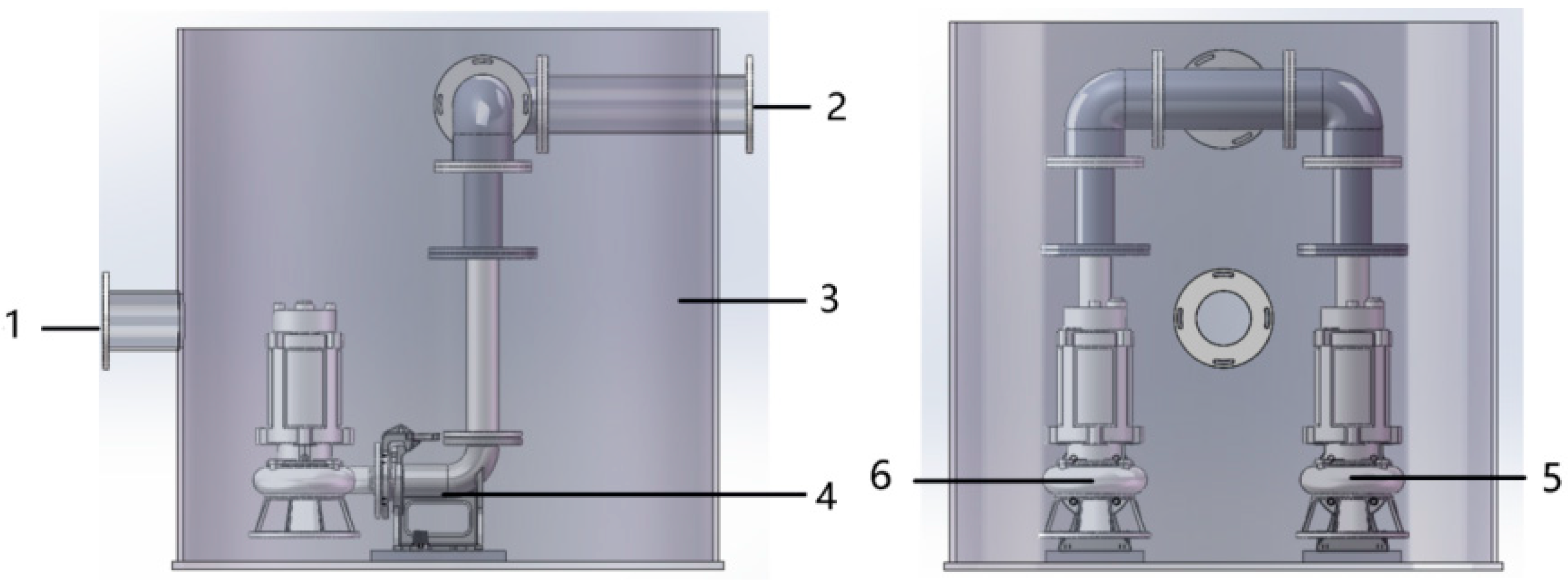
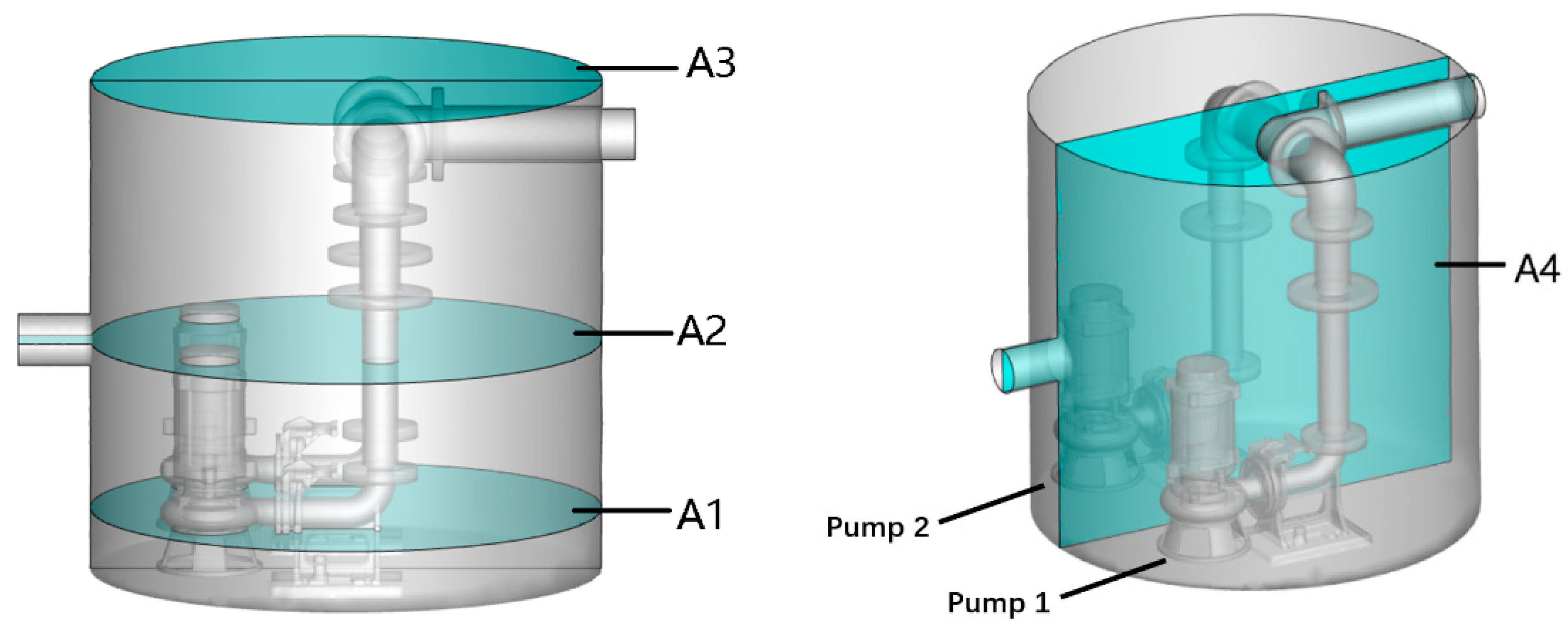
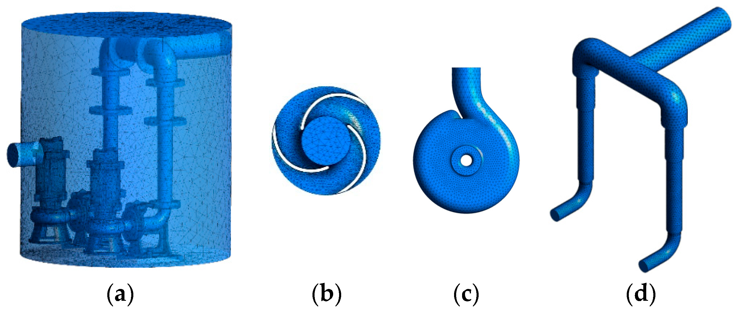
2.1. Calculation Model
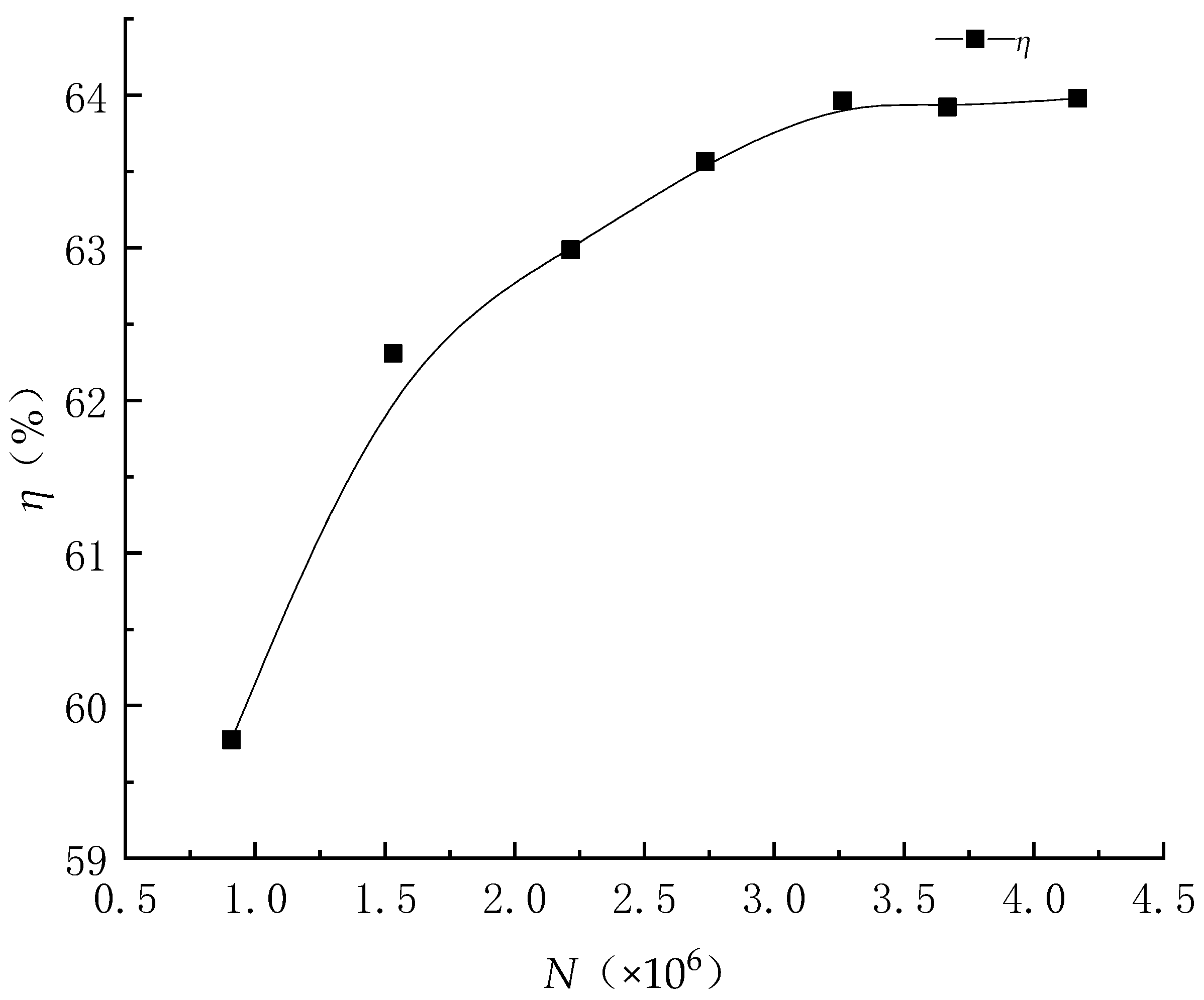
2.2. Meshing
2.3. Boundary Conditions and Turbulence Model
2.4. Calculation Formula
2.4.1. Control Equations
2.4.2. Hydraulic Performance Prediction
2.4.3. Uniformity of Flow Velocity Distribution
3. Energy and Internal Flow Characteristics Analysis
3.1. Energy Characteristics Analysis
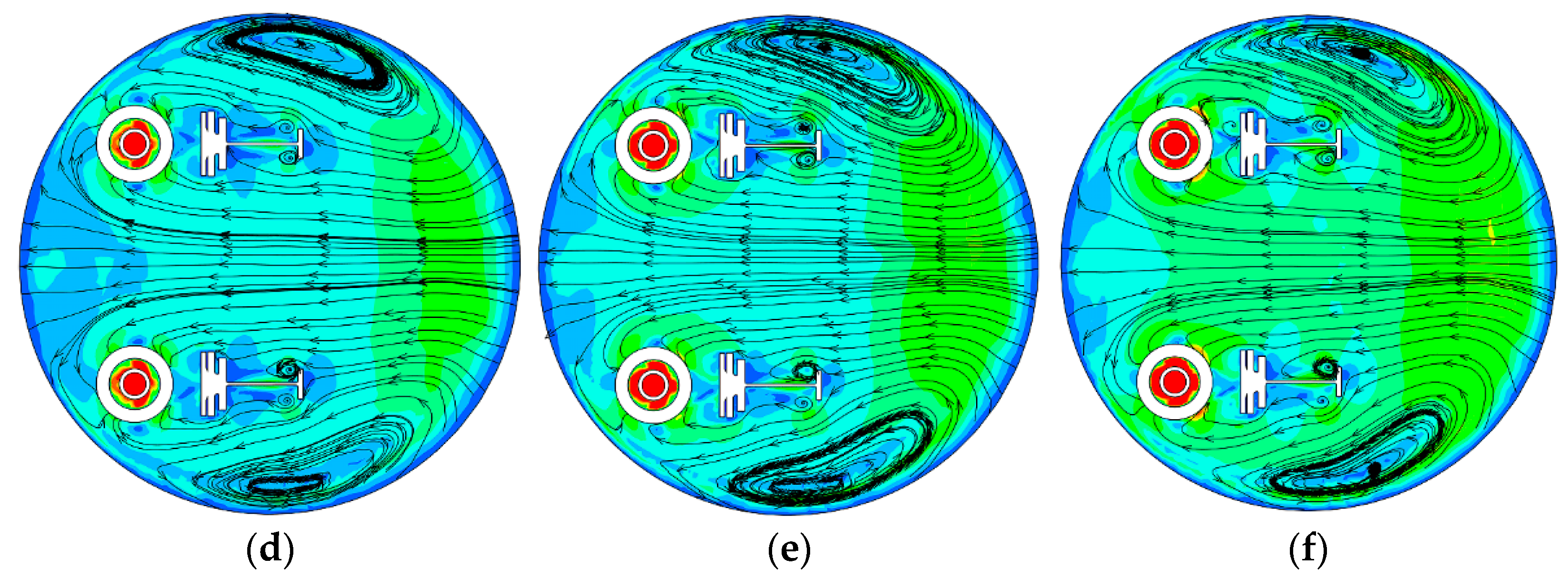
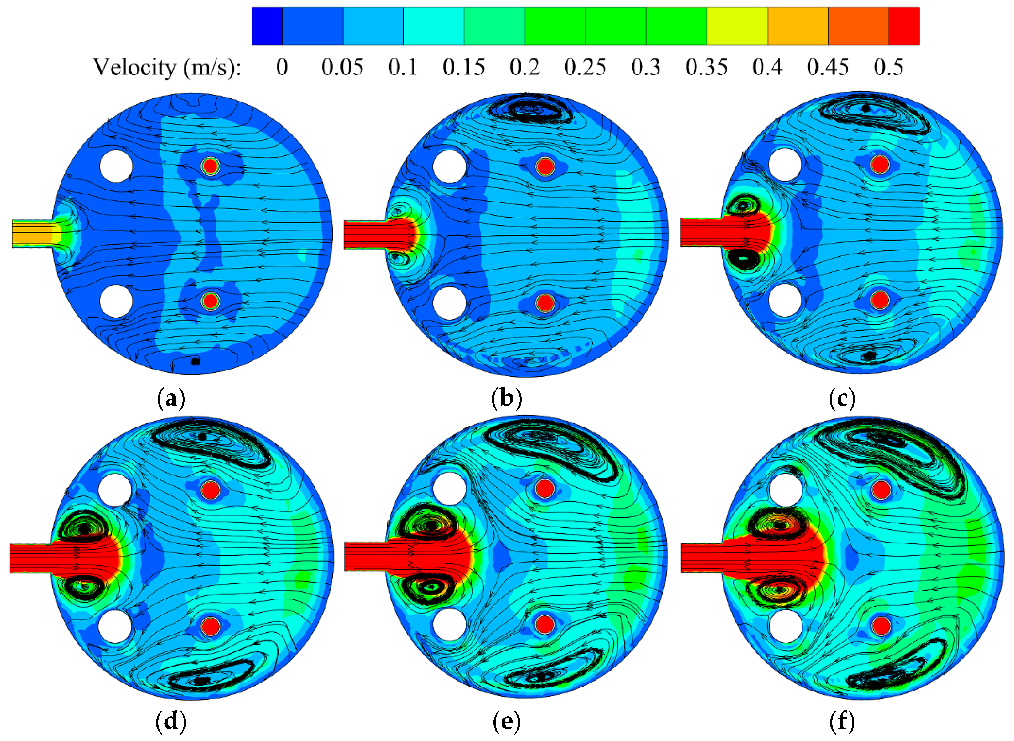
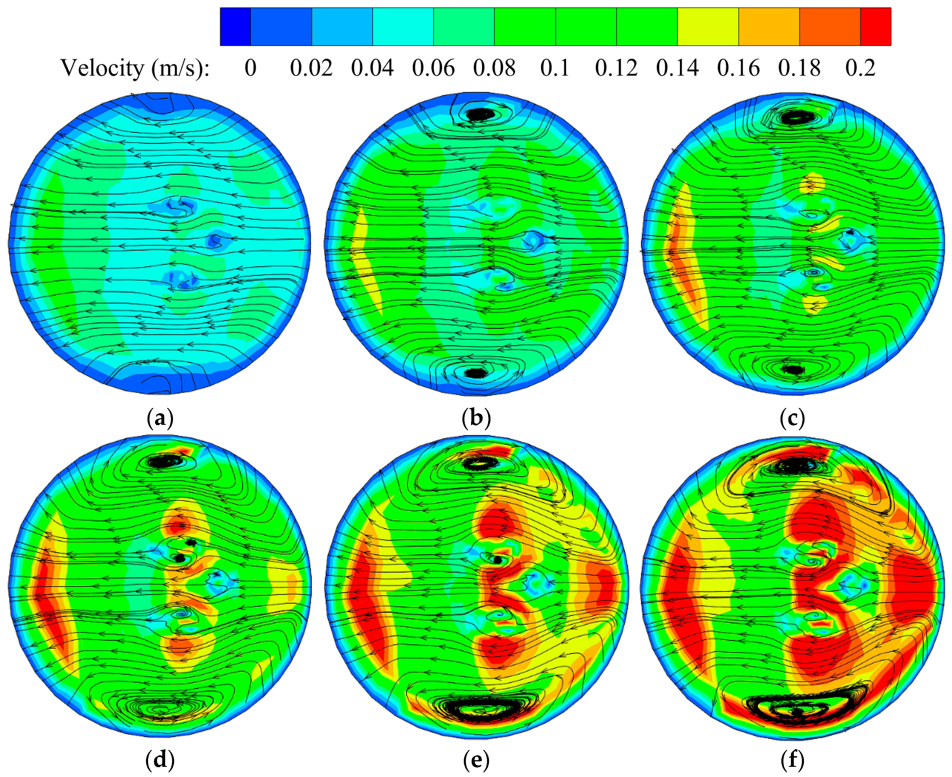
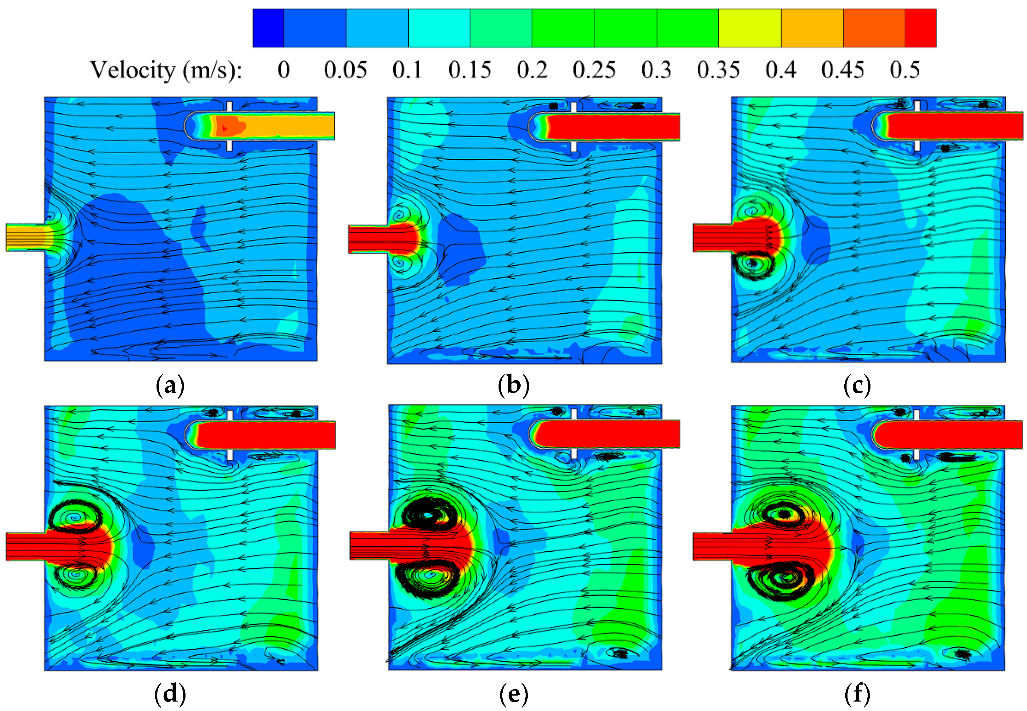
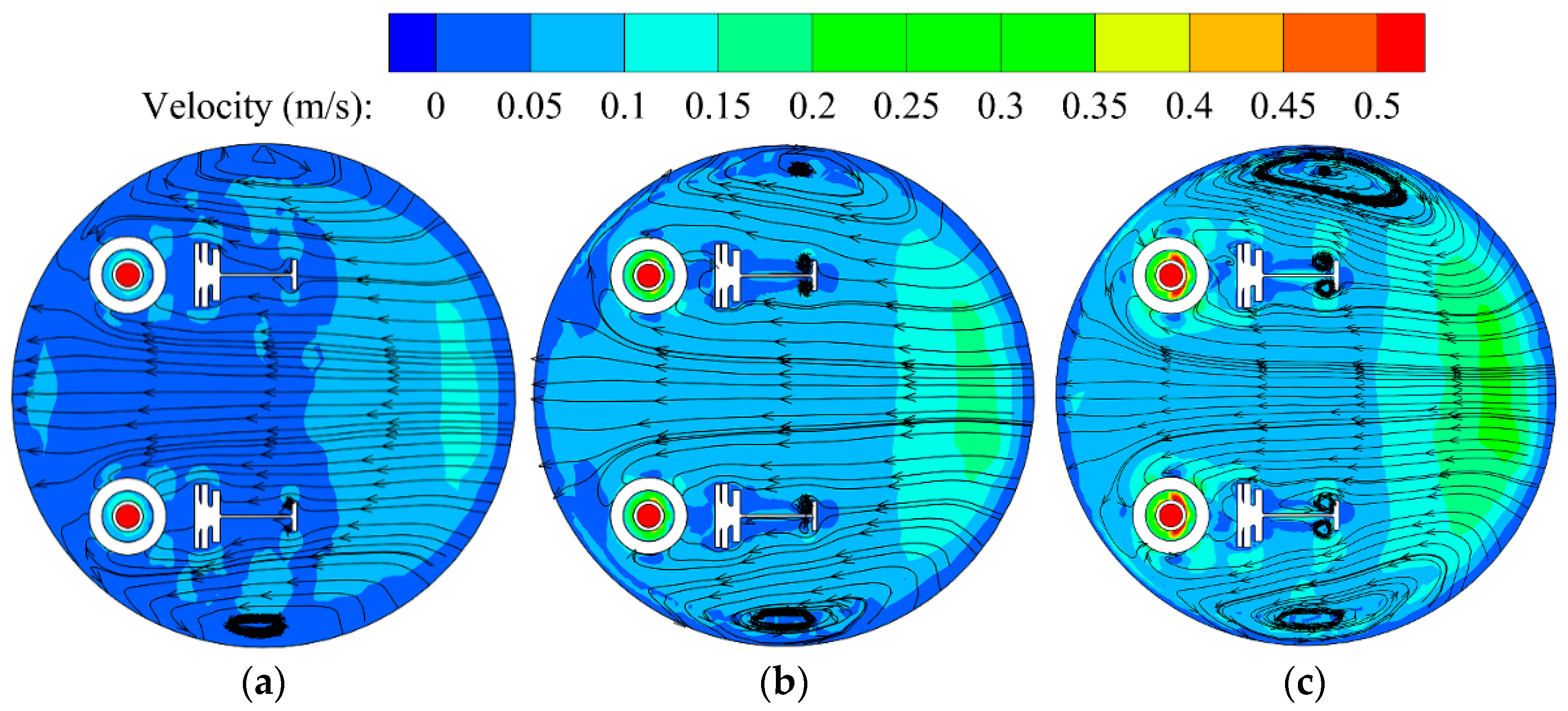
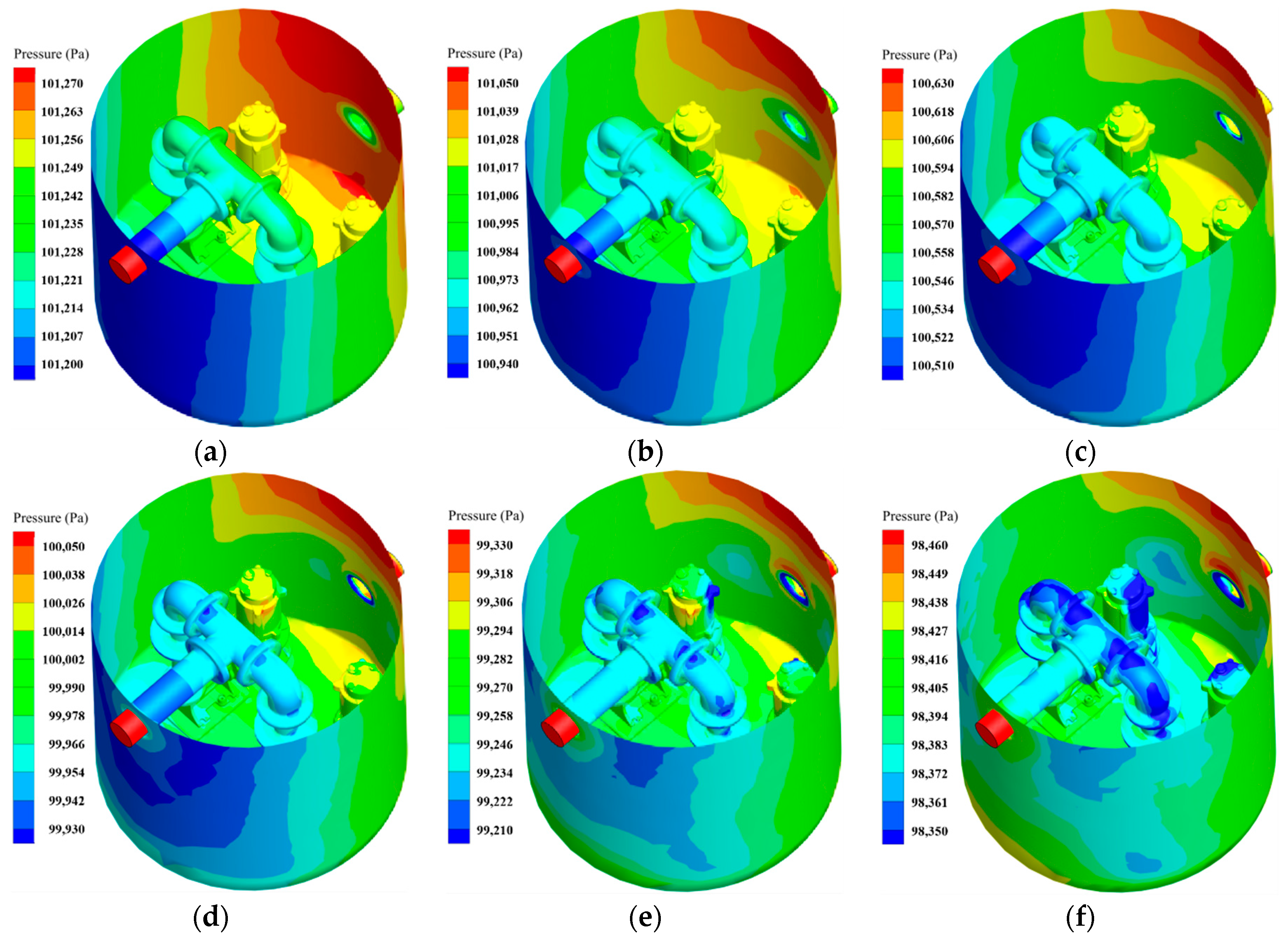
3.2. Analysis of Internal Flow Characteristics
4. Experiment Equipment, Test and Result Analysis
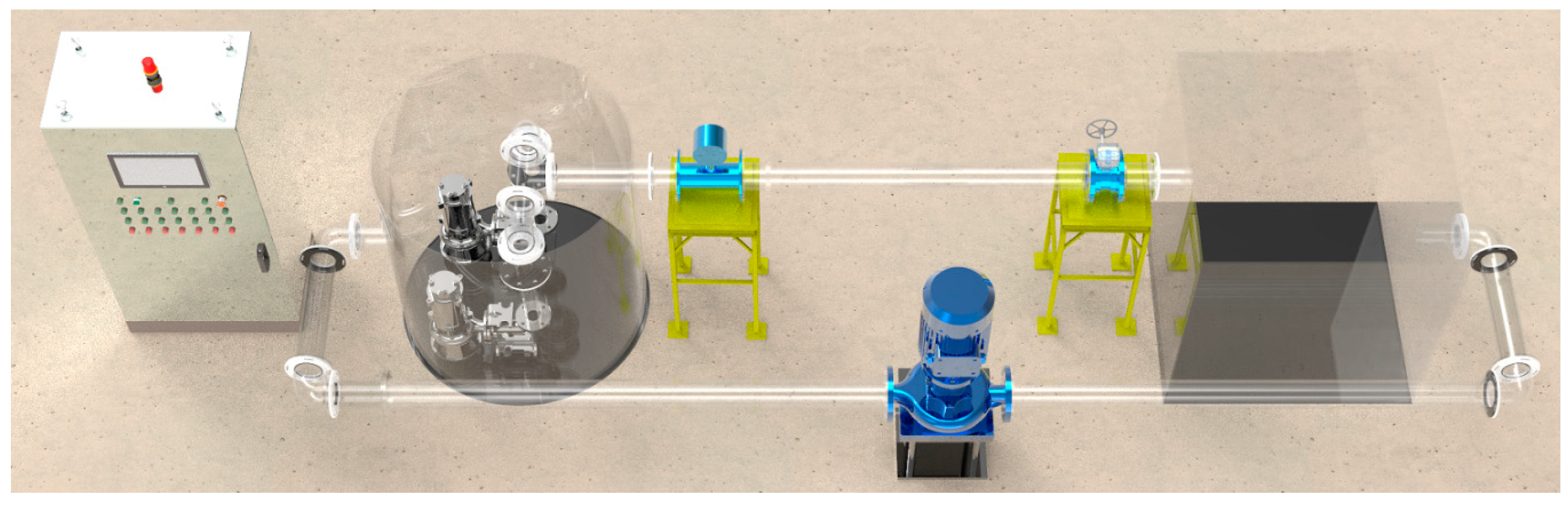
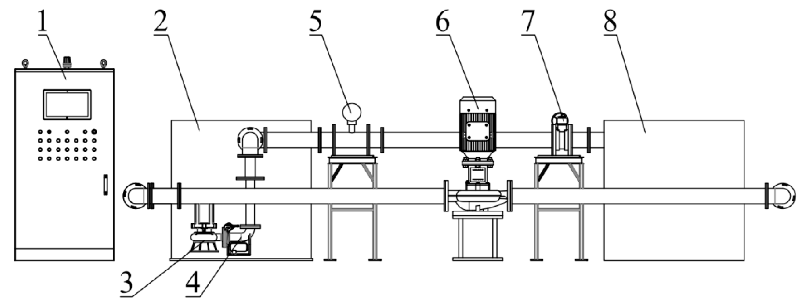
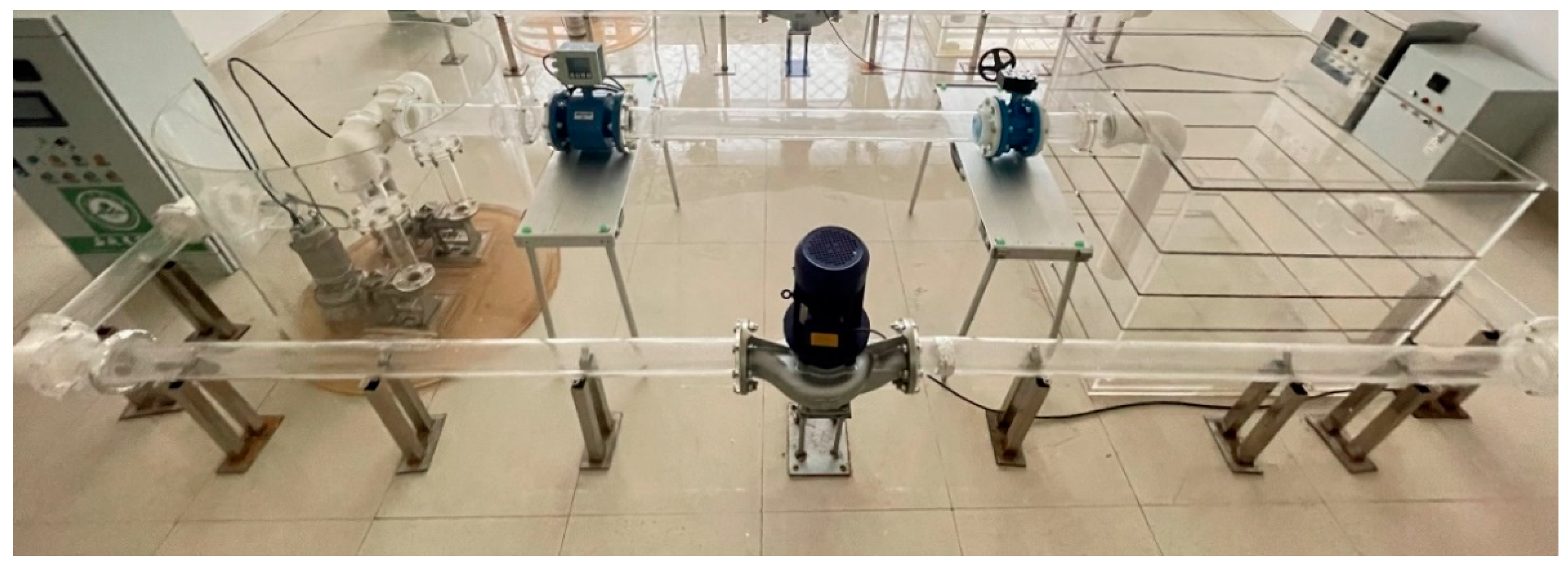
4.1. Test Bench Introduction
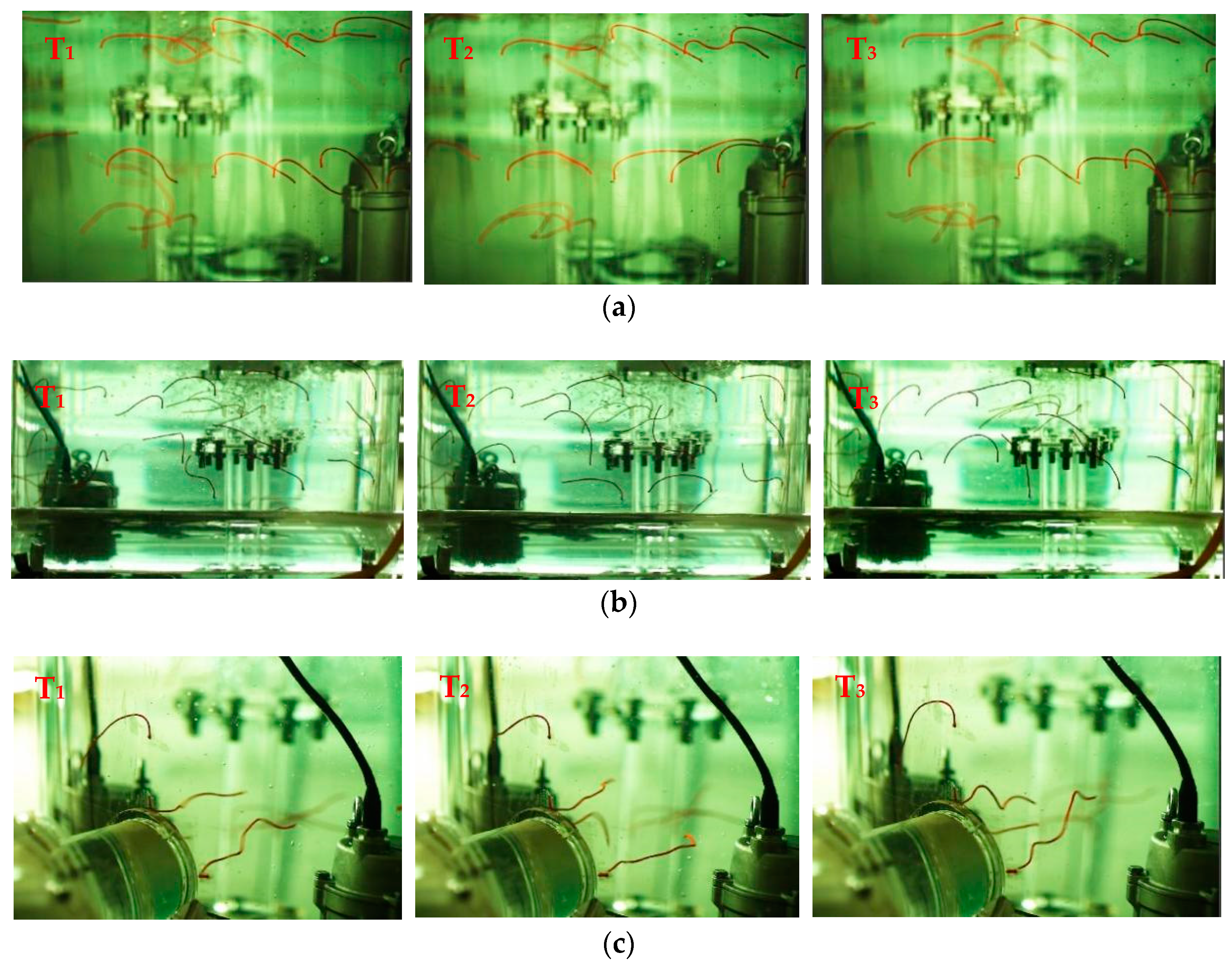
4.2. Analysis of Experimental Results
5. Conclusions
6. Suggestions
Author Contributions
Funding
Institutional Review Board Statement
Informed Consent Statement
Data Availability Statement
Conflicts of Interest
References
- Wang, D. Research on design development and application of integrated prefabricated pumping station. Gen. Mach. 2014, 7, 87–88. [Google Scholar]
- Fang, A.B. Research and application of integrated drainage pumping station. Build. Mater. Decor. 2020, 1, 218–219. [Google Scholar]
- Zhang, Z.; Wang, K.; Chen, K.; Yang, J.; Wang, S.; Wang, Y. Effects of different operation modes on flow characteristics and cylinder strength of integrated prefabricated pumping stations. China Rural. Water Conserv. Hydropower 2019, 4, 162–167. [Google Scholar]
- Li, Q.; Kang, C.; Teng, S.; Li, M. Optimization of Tank Bottom Shape for Improving the Anti. Deposition Performance of a Prefabricated Pumping Station. Water 2019, 11, 602. [Google Scholar]
- Wang, K.; Hu, J.; Liu, H.; Zhang, Z.; Zou, L.; Lu, Z. Research on the Deposition Characteristics of Integrated Prefabricated Pumping Station. Symmetry 2020, 12, 760. [Google Scholar] [CrossRef]
- Zhang, B.; Cheng, L.; Xu, C.; Wang, M. The Influence of Geometric Parameters of Pump Installation on the Hydraulic Performance of a Prefabricated Pumping Station. Energies 2021, 14, 1039. [Google Scholar] [CrossRef]
- Iacob, N.; Drăgan, N. Dynamic Analysis of a Centrifugal Pump using CFD and FEM Methods. Hidraulica 2019, 4, 29–37. [Google Scholar]
- Ramakrishna, R.; Hemalatha, S.; Rao, D.S. Analysis and performance of centrifugal pump impeller. Mater. Today Proc. 2022, 50, 5. [Google Scholar] [CrossRef]
- Kumar, S.V.; Han, X.; Kang, Y.; Li, D.; Zhao, W.; Selamat, F.E.; Wan Izhan, W.H.I.; Baharudin, B.S.; Bellary, S.A.I. Upgradation in efficiency of centrifugal pump. Asian J. Multidimens. Res. 2021, 10, 32–34. [Google Scholar]
- Tong, Z.; Xin, J.; Tong, S.; Yang, Z.; Zhao, J.; Mao, J. Internal flow structure, fault detection, and performance optimization of centrifugal pumps. J. Zhejiang Univ.-Sci. A Appl. Phys. Eng. 2020, 21, 85–117. [Google Scholar] [CrossRef]
- Al-Obaidi, A.R. Numerical investigation on effect of various pump rotational speeds on performance of centrifugal pump based on CFD analysis technique. Int. J. Modeling Simul. Sci. Comput. 2021, 12, 2150045. [Google Scholar] [CrossRef]
- Shunya, T.; Shinichi, K.; Shinichiro, E.; Masahiro, M. Effect of diffuser vane slit on rotating stall behavior and pump performance in a centrifugal pump. J. Phys. Conf. Ser. 2022, 2217, 012054. [Google Scholar]
- Tan, M.; Lu, Y.; Wu, X.; Liu, H.; Tian, X. Investigation on performance of a centrifugal pump with multi-malfunction. J. Low Freq. Noise Vib. Act. Control 2020, 40, 740–752. [Google Scholar] [CrossRef]
- Susilo, S.H.; Setiawan, A. Analysis of the number and angle of the impeller blade to the performance of centrifugal pump. EUREKA Phys. Eng. 2021, 5, 62–68. [Google Scholar] [CrossRef]
- Ding, H.; Li, Z.; Gong, X.; Li, M. The influence of blade outlet angle on the performance of centrifugal pump with high specific speed. Vacuum 2019, 159, 239–246. [Google Scholar] [CrossRef]
- Lila, A.; Mathieu, S.; Idir, B.; Smaine, K. Numerical Assessment of the Hydrodynamic Behavior of a Volute Centrifugal Pump Handling Emulsion. Entropy 2022, 24, 221. [Google Scholar] [CrossRef]
- Deepak, M.; Tony, K.; Atma, P.; Sajid, A.; Faik, H. Effect of Geometric Configuration of the Impeller on the Performance of Liquivac Pump: Single Phase Flow (Water). Fluids 2022, 7, 45. [Google Scholar] [CrossRef]
- Yu, T.; Shuai, Z.; Jian, J.; Wang, X.; Ren, K.; Dong, L.; Li, W.; Jiang, C. Numerical study on hydrodynamic characteristics of a centrifugal pump influenced by impeller-eccentric effect. Eng. Fail. Anal. 2022, 138, 106395. [Google Scholar] [CrossRef]
- Elyamin, G.R.H.A.; Bassily, M.A.; Khalil, K.Y.; Gomaa, M.S. Effect of impeller blades number on the performance of a centrifugal pump. Alex. Eng. J. 2019, 58, 39–48. [Google Scholar] [CrossRef]
- Zhaoheng, L.; Fangfang, Z.; Faye, J.; Ruofu, X.; Ran, T. Influence of the hydrofoil trailing-edge shape on the temporal-spatial features of vortex shedding. Ocean. Eng. 2022, 246, 110645. [Google Scholar]
- Menter, F.R. Zonal two equation k.ω turbulence models for aerodynamic flows. In Proceedings of the 23rd Fluid Dynamics, Plasmadynamics, and Lasers Conference, Orlando, FL, USA, 6–9 July 1993; p. 2906. [Google Scholar]
- Lu, Z.; Xiao, R.; Tao, R.; Li, P.; Liu, W. Influence of guide vane profile on the flow energy dissipation in a reversible pump-turbine at pump mode. J. Energy Storage 2022, 49, 104161. [Google Scholar] [CrossRef]
- Fang, X.; Hou, Y.; Cai, Y.; Chen, L.; Lai, T.; Chen, S. Study on a high-speed oil-free pump with fluid hydrodynamic lubrication. Adv. Mech. Eng. 2020, 12, 1687814020945463. [Google Scholar] [CrossRef]
- Stuparu, A.; Baya, A.; Bosioc, A.; Anton, L.; Mos, D. Experimental investigation of a pumping station from CET power plant Timisoara. IOP Conf. Ser. Earth Environ. Sci. 2019, 240, 032018. [Google Scholar] [CrossRef]
- Hassan, S.M.; Salman, S. Effects of impeller geometry modification on performance of pump as turbine in the urban water distribution network. Energy 2022, 255, 124550. [Google Scholar]
- Liu, Y.; Xia, Z.; Deng, H.; Zheng, S. Two-Stage Hybrid Model for Efficiency Prediction of Centrifugal Pump. Sensors 2022, 22, 4300. [Google Scholar] [CrossRef] [PubMed]
- Francesco, P.; Maurizio, G. An Operative Framework for the Optimal Selection of Centrifugal Pumps As Turbines (PATs) in Water Distribution Networks (WDNs). Water 2022, 14, 1785. [Google Scholar]
- Parkes, A.I.; Sobey, A.J.; Hudson, D.A. Physics-based shaft power prediction for large merchant ships using neural networks. Ocean. Eng. 2018, 166, 92–104. [Google Scholar] [CrossRef]
- Wang, X.; Zhang, J.; Li, Z. Numerical Simulation of Internal Flow Field of Self-Designed Centrifugal Pump. In Proceedings of the 2021 International Conference on Fluid and Chemical Engineering (ICFCE 2021), Wuhan, China, 29–30 October 2021; pp. 158–166. [Google Scholar]
- Sun, Z.; Yu, J.; Tang, F. The Influence of Bulb Position on Hydraulic Performance of Submersible Tubular Pump Device. J. Mar. Sci. Eng. 2021, 9, 831. [Google Scholar] [CrossRef]


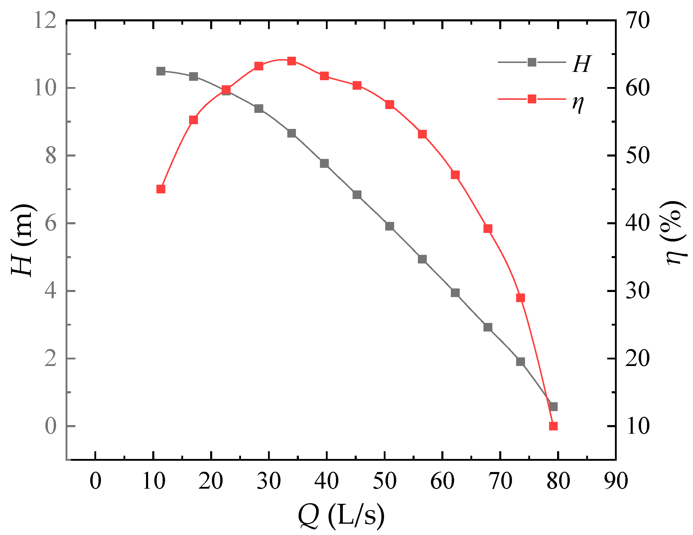
| Flow Rate Q (m3/h) | Head H (m) | Efficiency η (%) |
|---|---|---|
| 11.31 (0.33Qd) | 10.50 | 45.05 |
| 16.96 (0.50Qd) | 10.33 | 55.28 |
| 22.62 (0.67Qd) | 9.91 | 59.77 |
| 28.27 (0.83Qd) | 9.39 | 63.22 |
| 33.93 (1.00Qd) | 8.66 | 63.96 |
| 39.58 (1.17Qd) | 7.77 | 61.78 |
| 45.24 (1.33Qd) | 6.84 | 60.36 |
| 50.89 (1.50Qd) | 5.91 | 57.54 |
| 56.55 (1.67Qd) | 4.93 | 53.17 |
| 62.20 (1.83Qd) | 3.94 | 47.15 |
| 67.86 (2.00Qd) | 2.92 | 39.18 |
| 73.51 (2.17Qd) | 1.90 | 28.97 |
| 79.17 (2.33Qd) | 0.57 | 9.98 |
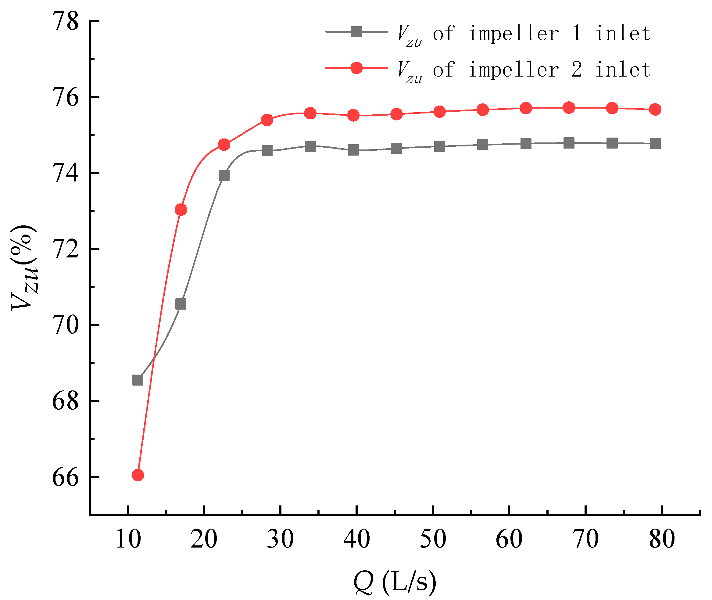
| Flow Rate Q (m3/h) | Water Pump 1 Impeller Inlet Flow Rate Uniformity (%) | Water Pump 2 Impeller Inlet Flow Rate Uniformity (%) |
|---|---|---|
| 11.31 (0.33Qd) | 68.55 | 66.05 |
| 16.96 (0.50Qd) | 70.55 | 73.03 |
| 22.62 (0.67Qd) | 73.93 | 74.74 |
| 28.27 (0.83Qd) | 74.59 | 75.40 |
| 33.93 (1.00Qd) | 74.70 | 75.57 |
| 39.58 (1.17Qd) | 74.61 | 75.52 |
| 45.24 (1.33Qd) | 74.65 | 75.55 |
| 50.89 (1.50Qd) | 74.70 | 75.61 |
| 56.55 (1.67Qd) | 74.74 | 75.66 |
| 62.20 (1.83Qd) | 74.77 | 75.70 |
| 67.86 (2.00Qd) | 74.79 | 75.72 |
| 73.51 (2.17Qd) | 74.79 | 75.70 |
| 79.17 (2.33Qd) | 74.78 | 75.67 |
Publisher’s Note: MDPI stays neutral with regard to jurisdictional claims in published maps and institutional affiliations. |
© 2022 by the authors. Licensee MDPI, Basel, Switzerland. This article is an open access article distributed under the terms and conditions of the Creative Commons Attribution (CC BY) license (https://creativecommons.org/licenses/by/4.0/).
Share and Cite
Xie, C.; Yuan, Z.; Feng, A.; Wang, Z.; Wu, L. Energy Characteristics and Internal Flow Field Analysis of Centrifugal Prefabricated Pumping Station with Two Pumps in Operation. Water 2022, 14, 2705. https://doi.org/10.3390/w14172705
Xie C, Yuan Z, Feng A, Wang Z, Wu L. Energy Characteristics and Internal Flow Field Analysis of Centrifugal Prefabricated Pumping Station with Two Pumps in Operation. Water. 2022; 14(17):2705. https://doi.org/10.3390/w14172705
Chicago/Turabian StyleXie, Chuanliu, Zhenyang Yuan, Andong Feng, Zhaojun Wang, and Liming Wu. 2022. "Energy Characteristics and Internal Flow Field Analysis of Centrifugal Prefabricated Pumping Station with Two Pumps in Operation" Water 14, no. 17: 2705. https://doi.org/10.3390/w14172705
APA StyleXie, C., Yuan, Z., Feng, A., Wang, Z., & Wu, L. (2022). Energy Characteristics and Internal Flow Field Analysis of Centrifugal Prefabricated Pumping Station with Two Pumps in Operation. Water, 14(17), 2705. https://doi.org/10.3390/w14172705