Article

Low-Calcium Cave Dripwaters in a High CO2 Environment: Formation and Development of Corrosion Cups in Postojna Cave, Slovenia

Karst Research Institute ZRC SAZU, Titov trg 2, 6230 Postojna, Slovenia
*
Author to whom correspondence should be addressed.
Water 2021, 13(22), 3184; https://doi.org/10.3390/w13223184
Submission received: 30 September 2021 / Revised: 5 November 2021 / Accepted: 8 November 2021 / Published: 11 November 2021
(This article belongs to the Special Issue Geochemical Processes of Karst and Karst Paleoenvironments)

Abstract

:
Speleothems have proven to be one of the most reliable terrestrial archives for palaeoclimate research. However, due to the complexity of karst systems, long-term monitoring and high-resolution analyses of the cave atmosphere and water geochemistry have become essential to better constrain the factors that control calcite growth and how geochemical palaeoclimate proxies are encoded into speleothems. While calcite precipitation incorporates the palaeoclimate signals into the speleothem fabric, certain conditions in caves can favour dissolution, which may form hiatuses or even destroy these signals. In extreme cases, in-cave dissolution by dripwater can form cup-shaped features (i.e., corrosion cups), which were the main focus of this study. The study site in Postojna Cave, Slovenia was investigated through cave climate monitoring and drip and cup water sampling, which took place during 2017–2021. We found that the cups are fed by low-calcium drips as the consequence of the thin rock overburden above the cave. Due to the specific configuration of the airflow pathways, the study site accumulates high levels of CO2 (>10,000 ppm), which shifts low-calcium dripwater into undersaturation. This causes dissolution on the rock surfaces and speleothems on the cave floor. The results of this study have broader significance in addressing the suitability of cave environments and speleothems used in paleoclimate research.

Graphical Abstract

1. Introduction

Speleothems provide robust palaeoclimate archives in continental settings, because they can be absolutely dated using U-series methods and contain multiple palaeoclimate proxy records. Although extensive studies have been carried out to understand the mechanisms of palaeoclimate signal occlusion into stalagmites, it remains a challenging task due to the inherent complexity of karst systems and the processes involved [1]. Therefore, it is important to fill the knowledge gaps in a broader context: the weather and climate controls, the (bio)geochemistry in the soil zone, the hydrology of the karst vadose zone, the physical and chemical processes on a microscale and, finally, the conditions in the cave environment that form an incubator for speleothem growth [2,3,4,5,6,7].
CO2 is one of the main regulators of speleothem growth, because it determines the amount of calcium dissolved in water percolating towards the cave and the amount of calcium carbonate precipitated in caves in the form of speleothems. Since CO2 sources and sinks are highly variable both spatially and temporally, it is important to record the CO2 distribution in caves and monitor its variations with high resolution [3,8,9,10,11,12,13,14,15,16]. In mid-latitude, high-latitude and continental caves, seasonal variations in CO2 partial pressure (pCO2) are a common feature of the cave climate regularly observed [3,12,17,18,19]. The seasonal variations of pCO2 in cave air and the corresponding variations in the calcite deposition rates are usually influenced by cave ventilation, which, in turn, is frequently driven by the chimney effect [19]. In a typical situation of caves with only one entrance—which can still be ventilated by the chimney effect—more ventilation in one season leads to a reduction of pCO2 in the cave air, more degassing of the dripwater and more abundant precipitation of calcite [12,19]. In the other seasons, ventilation may be restricted, for example, in descending caves with only one entrance, which act as cold traps in the warm season and are only ventilated in the colder season when cold and dense outside air flows into the cave [11,12,18]. In such cases, a build-up of CO2 can limit or prevent calcite precipitation altogether and, in extreme cases, lead to dissolution. Alternatively, a lack of or reduced speleothem growth can be associated with colder climates and/or higher altitudes due to a thin soil zone that does not provide sufficient CO2 for the initial dissolution of the host rock [20].
The growth, architecture and micropetrography of speleothems affected by occasional periods of dissolution have been investigated in only a handful of studies [2,21]. Other studies refer to “hindered stalagmite growth”, “near-zero growth” or explicitly to “dissolution by undersaturated dripwater” in certain cave settings but have yet to be subjected to detailed studies [12,14,16,22]. However, dissolution in the context of specific processes, such as condensation corrosion [23], mixing corrosion [24], microbially mediated dissolution [25], hypogene speleogenesis [26] or prior calcite precipitation (PCP) [27], has received some attention. One aim of this work is to investigate the geochemical and cave climate conditions that promote local dissolution in a cave that is rich in speleothems, which results in extensive damage to the speleothems and the palaeoclimate signals that they contain.
A model of the evolution of water-carbonate chemistry in the karst system facilitates understanding of the processes and constraints at the conceptual level [1,28,29]. Due to the rapid kinetics of calcite dissolution, water percolating through the vadose zone reaches equilibrium with calcite and the pCO2 value of the vadose zone within a few tens of meters. When this water enters a cave where the atmosphere has lower pCO2 than before, this causes the degassing of excess CO2, leading to supersaturation of the water with respect to calcite and, finally, calcite precipitation [30]. In a conceptual model of water evolution in Figure 1, these processes are shown with blue arrows. The amount of dissolved calcium depends on the initial pCO2 in the water and the conditions in the vadose zone, which either replenish CO2 during dissolution (open system conditions; A to C) or deplete CO2 (closed system conditions; A to B). Finally, the degree of calcite supersaturation depends on the pCO2 of the cave air.
At the other end of the extreme, there are several possible scenarios for dissolution in the cave’s environment, represented by the red arrows in Figure 1.
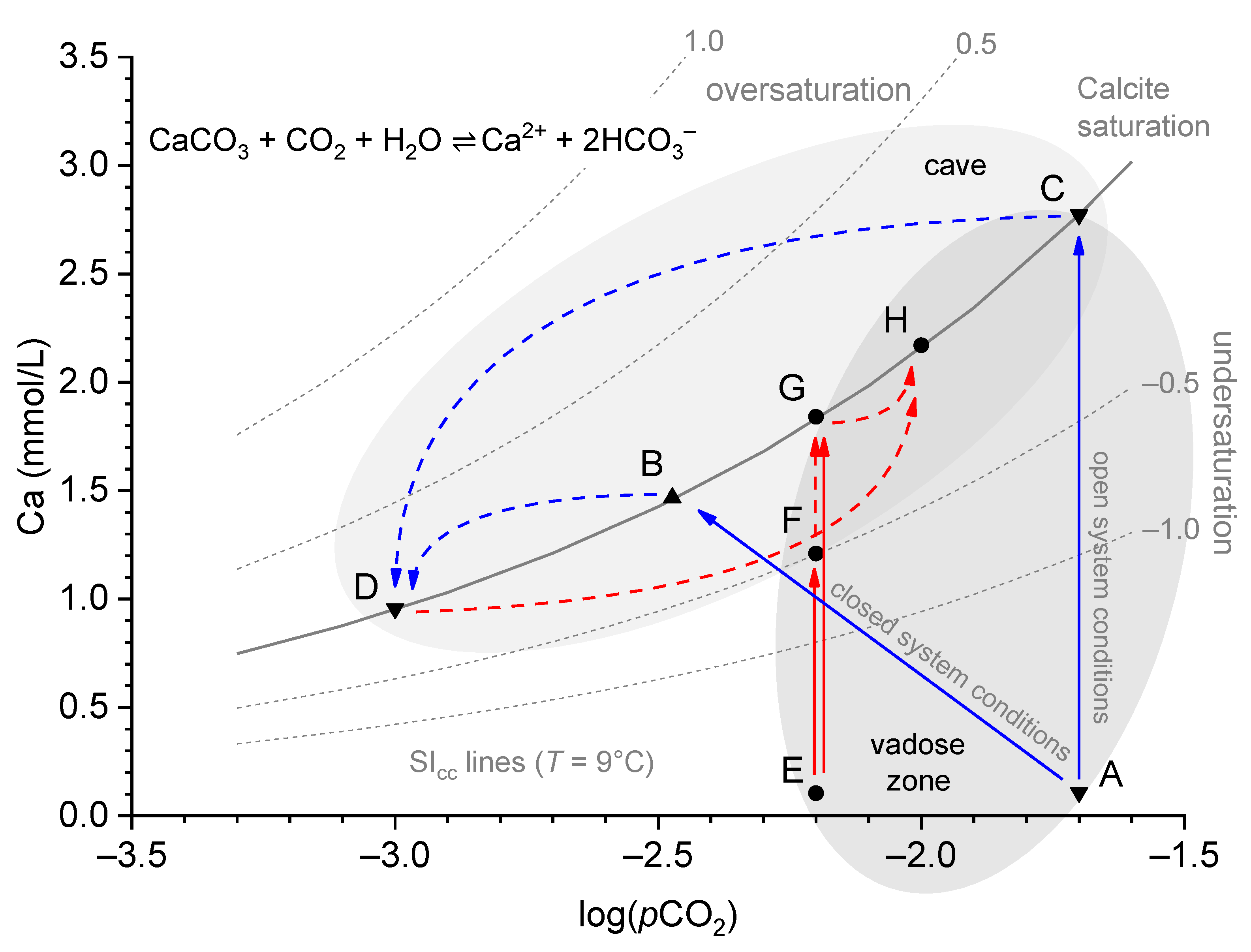
  • The water arrives in the cave undersaturated (e.g., due to rapid flow and incomplete saturation; E to F) and causes dissolution in the cave (F to G).
  • The water arrives saturated in the cave but encounters a higher pCO2 than in the vadose zone, or it has been saturated under closed system conditions, replenishing the spent CO2 from the cave air (E to G to H).
  • The dripping water degasses and equilibrates to the low pCO2 of the cave air, but after a conceivable increase in pCO2, it equilibrates to this new state (C to D to H).
  • Mixing corrosions due to the effect of undersaturation of the calcite, even if the mixed solutions were previously saturated (not shown).
The strongest dissolution would occur when pCO2 fluctuations in the cave air are the greatest (C to D to H). Weaker precipitation would keep the water supersaturated, and only a sharp increase in pCO2 would move the water into the undersaturated region. However, how well such a simple model reflects real-world scenarios depends on the study sites or the observed drip spots, but nevertheless, valuable insights can be gained and boundary conditions found.
The aim of this paper is to present an example of calcite dissolution occurring within a cave, thus far presented only theoretically in Figure 1, and to investigate the real-world conditions necessary for calcite dissolution to occur. We examined the cup-shaped dissolution features, so-called “corrosion cups”, found in large numbers in the Pisani Passage of Postojna Cave, using the cave climate and dripwater monitoring data collected in 2017–2021. Previous studies have found that Pisani Passage has the highest CO2 concentrations in Postojna Cave and extreme pCO2 gradients during warm periods [15,32,33]. In the current study, we compare the observations of the cave climate with hydrochemical analyses and use basic models of carbonate chemistry to explain the formation and growth of corrosion cups that have implications for the corrosion of speleothems.

2. Materials and Methods

2.1. Study Site

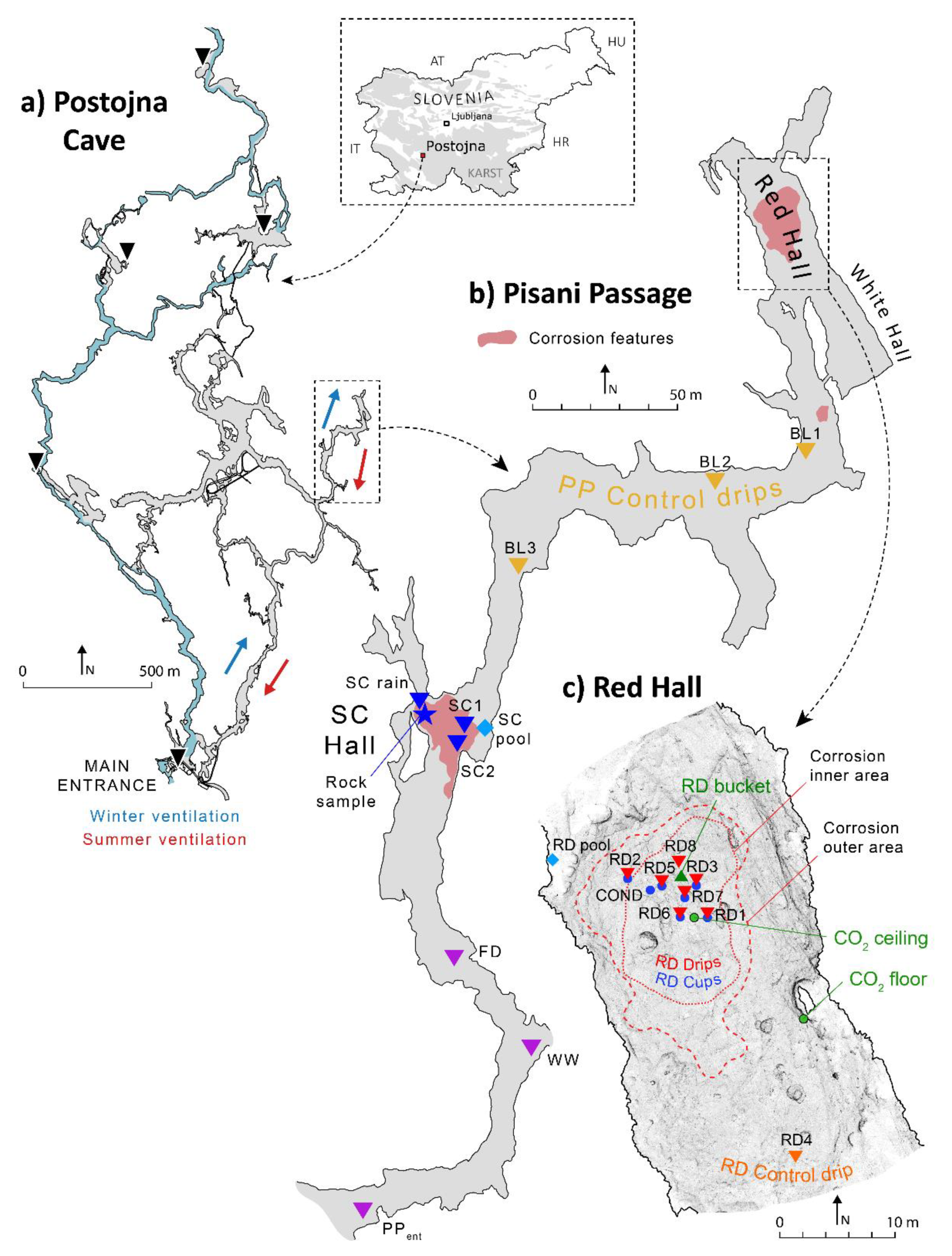
2.1.1. Postojna Cave

Postojna Cave is a world-famous show cave in Central Slovenia near the town of Postojna (Figure 2a). It is an extensive cave system comprising 24 km of passages connected to the surface by five main entrances [34]. The system extends horizontally over several levels—the lower level is epiphreatic and drains the Pivka River, while the upper level is dry and consists of large breakdown chambers and passages decorated with speleothems. The main entrance of the cave is located at the southern end near Pivka Ponor at 529 m a.s.l. The rock overburden is 30–100 m thick [35]. The cave is located within the extensive Dinaric (NW–SE) fault zones, and active micro-deformations are present throughout the cave, especially in the breakdown chambers [36]. The cave system is characterised by efficient cave ventilation, which changes direction seasonally. In the colder seasons, an upward airflow (updraft) directs air from the main entrance of the cave to the higher elevation entrances, while, in the warmer seasons, the direction of the airflow is reversed (downdraft). The average ambient cave air temperature is 9–11 °C, depending on the location. The nearest national meteorological station is in Postojna, 1.2 km SSW of the main cave entrance [37]. The average air temperature in Postojna is 9.3 °C, with July being the warmest month (19 °C) and January the coldest (0.1 °C). Postojna receives an average of 1500 mm of precipitation per year, with the least in January, February and July and the most in September, November and December.

2.1.2. Pisani Passage and Red Hall

Postojna Cave has a few dead-end side passages, the largest being Pisani Passage (Figure 2b). Pisani Passage (PP) is located in the easternmost part of the system and extends ~500 m northwards along the southwest-facing fault zones. The passage is formed from relatively pure Upper Cretaceous limestones, with rare intercalations of chert lenses and dolomitised limestones [38]. The passage is about 5 m wide and 4 m high. The largest spaces associated with the crossing of several active faults [38,39] are in breakdown chambers halfway down the passage (SC Hall) and at the end of the passage (Red Hall, “Rdeča dvorana”, abbr. RD, and White Hall, abbr. WH). There, the thickness of the overburden is lowest (~30 m). Apart from breakdown chambers filled with loose rock, the interior of the passage is filled with fluvial sediments remaining from the former river flow and overlain by a rich cover of speleothems. Although there is no accessible opening to the surface, PP is well-ventilated throughout its extent. The average air temperature is 8.8 °C and shows very little seasonal variation (±0.1 °C), but a gradual warming of about 0.08 °C per year has been observed over the last ten years [15]. The air pCO2 dynamics and specific phenomena relevant to this study were investigated previously [15]. The surface above PP is covered by beech and fir forests with thick, rocky soils about 20 cm deep, with pockets more than 1 m deep above the Red Hall [40].
The distinct dissolution features in PP are found in abundance in only two sites already mentioned in earlier studies [38,41]. The first location is in the SC Hall below the high chimney and the other in the lowest section of the Red Hall (Figure 2b,c). The Red Hall and White Hall form a single chamber with a volume of about 6800 m3. The intersection of prominent faults has resulted in the dislodgment and accumulation of boulders that cover most of the passage floor. The sides and the most distant section of PP are covered with fluvial loam sediments. Many massive (>2 m high and >20 cm in diameter) stalagmites have grown in the Red and White Halls. In general, all other surfaces are covered by either a thick flowstone cover or a thin (few mm thick) flowstone crust of brown or red colour, hence the name Red Hall (Figure 3a). No signs of dissolution features were found on the ceiling of the Red Hall. Soda straw stalactites predominate on the NE part of the ceiling, while the SW part is mostly bare, indicating relatively recent collapses.
Dissolution features are concentrated under active drip spots and exhibit a variety of shapes and sizes, ranging from shallow white indentations where only a flowstone crust is dissolved to ~50 cm deep and narrow tubes (Figure 3a). The most common are so-called corrosion cups, which are typically about 5 cm wide and 5–10 cm deep (e.g., RD5 and RD6), while RD1 is a wide, shallow dish-shaped feature (Figure 3b). Almost 400 corroded drip spots were found only in the localised deepest area in Red Hall. Some drip spots do not form cup-shaped cavities but, rather, semi-circular tubes or flutes, especially on sloping surfaces or in cases when the water drains efficiently. When the dripping water splashes into the cups, some of the water is displaced from the cup, and the cups are usually never completely filled with water. The splashing contributes to corrosion of the surfaces surrounding the cup, as can be seen for high-discharge drip RD1 (Figure 3b). The dissolution occurs irrespective of the surfaces, so that even stalagmites are strongly affected by the drips (Figure 3c). Interestingly, some corrosion cups are covered with flowstone and contain calcite crystals (RD2 in Figure 3d). Within the Red Hall, we have distinguished several areas characterised by different degrees of dissolution and precipitation. These are indicated by red dashed lines in Figure 2c and are explained below:
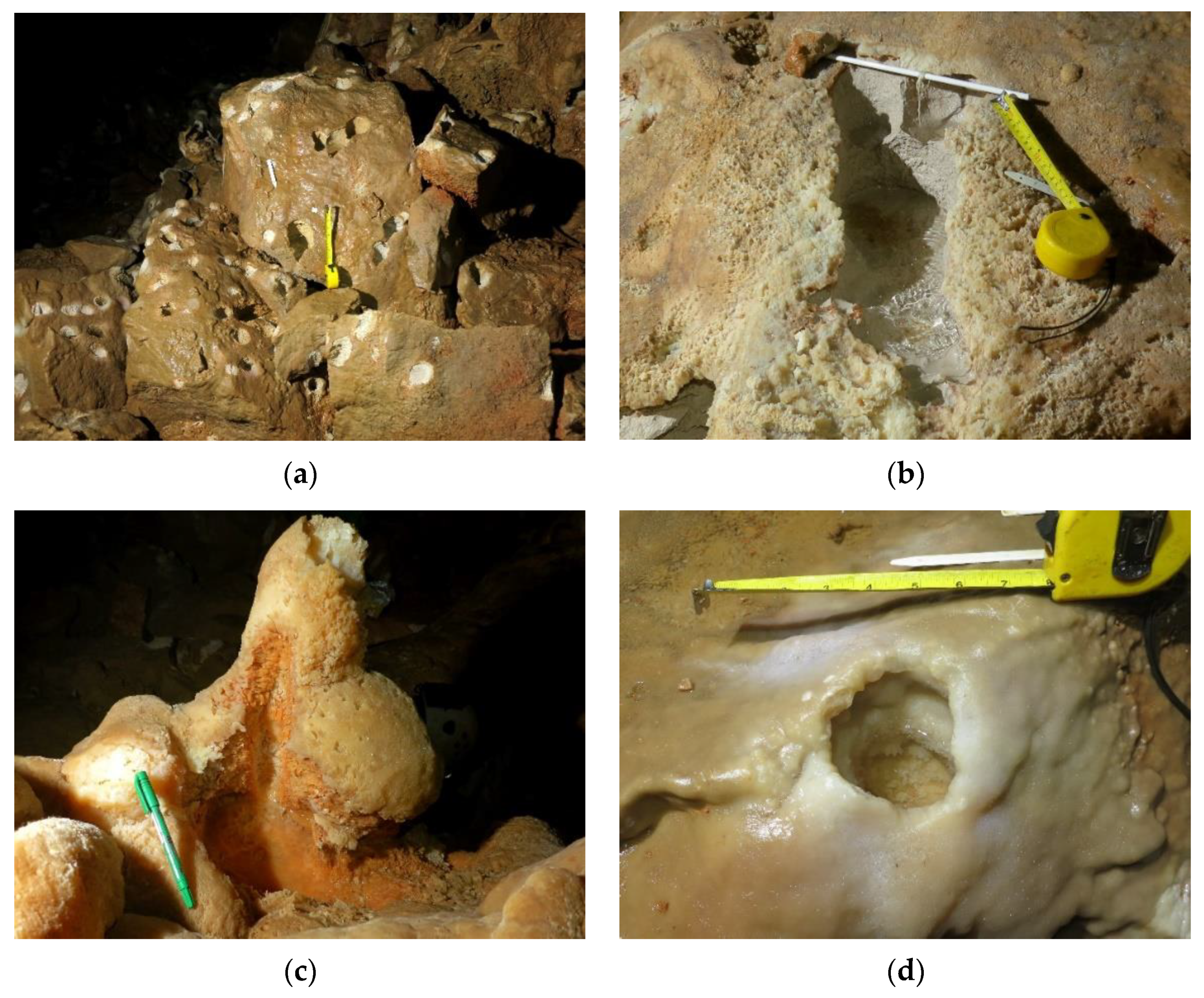
  • Inner corrosion area—contains only cups with bare rock surfaces and corroded speleothems (see the examples in Figure 3a–c).
  • Outer corrosion area—this area encompasses the inner area and contains cups whose upper rims are covered in flowstones or are completely covered by flowstones and often contain broken calcite crystals (e.g., RD2 cup in Figure 3d).
  • Outside the outer area—cups are rare or absent. Some stalagmites have indented tops but no pronounced corrosion (e.g., RD4). Dissolution takes place only hidden in thin fractures near the floor, through which high-CO2 air is introduced during downdrafts [15].

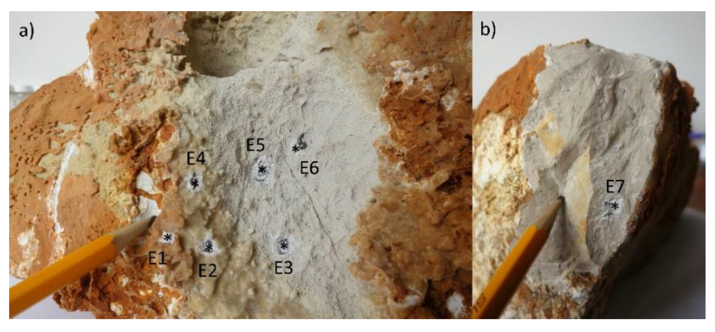
2.2. Bedrock Analysis

A rock sample containing two cups was taken from the cave and analysed for its elemental composition (the location in the SC Hall is marked in Figure 2b). The sample contained two cups, one deeper (2 cm) and one shallow (<1 cm), both with grey bare rock surfaces (Figure 4a). The rest of the rock surface is covered by a thin crust of yellow flowstone, which, in turn, is covered by a red flowstone crust. The analysis was carried out with an Agilent 5100 Inductively Coupled Plasma Optical Emission Spectrometer (ICP OES) at the Institute of Geology, Czech Academy of Sciences in Prague. To obtain milligram powder samples, seven distinct spots labelled E1–E7 were drilled on the surface, then dissolved in ~5% HCl and diluted to a 25-mL mark in a volumetric flask. The compositional analysis included the following elements, with their detection limits in parentheses: Al (0.002 ppm), Ba (0.001 ppm), Ca (0.001 ppm), Fe (0.001 ppm), K (0.004 ppm), Mg (0.001 ppm), Mn (0.0001 ppm), P (0.01 ppm), S (0.01 ppm), Si (0.002 ppm) and Sr (0.0001 ppm). The standard conditions and instrument settings recommended by the manufacturer were used (1200-W RF power, concentric nebuliser, nebuliser pressure 25 psi and sample uptake 2.5 mL/min).

2.3. Dripwater Hydrology

The drip count N was measured with two acoustic Stalagmate® (Driptych, UK) drip counters [42], whose positions were relocated occasionally to cover a wide range of dripping regimes. Occasionally, the drip count was measured manually with or without measuring the drip discharge Qdrip (mL/s) directly with a graduated vial and a stopwatch. For slow drip sites where only drip counting was practical, the discharge was calculated from the empirical function between the drip interval Δt and the drop mass mdrop reported in the literature m d r o p = m 0 + S Δ t 0.75 [43]. The function fitting parameters m0 and S were obtained by comparing data points where both the drip discharge and drip count N were measured, with the drop mass calculated as m d r o p = ρ w Q d r i p t N , where ρw is the water density (1 kg/dm3) and t is the time period. Finally, the missing dripwater discharge was then calculated as Q d r i p = N m d r o p ρ w t . The same equation was used to calculate a continuous series of drip discharges from drip counts obtained from stalagmites.
To evaluate the contribution of precipitation to recharge the drips in Pisani Passage, a “water balance” (WB) was calculated by subtracting the precipitation from the evapotranspiration on a monthly basis. Evapotranspiration was calculated with the Penman–Monteith equation [37].

2.4. Cave Air Monitoring

Continuous monitoring of the cave climate at Postojna Cave includes the pCO2, ambient air temperature and airflow velocity. Details of this monitoring setup can be found in a previous publication [15]. In the Red Hall, pCO2 was measured at two levels—one probe was located on the ceiling, directly above the inner corrosion area of the Red Hall, and the other probe was located above the floor at a distance of 20 m and 6.5 m below the ceiling probe, outside of the area affected by corrosion (Figure 2c). The ambient air pCO2 in the immediate vicinity of the water sampling sites was measured with a Vaisala GM70 portable CO2 metre using GMP222 or GMP252 probes (compensated at 25 °C, measuring range 0–10,000 ppm, resolution 1 ppm for GM252 and 10 ppm for GM222).

2.5. Water Sampling and Monitoring

Water sampling in PP took place at irregular intervals from winter 2017 to summer 2021, with a total of 295 samples collected either in the form of dripwater (drip), water in corrosion cups (cup), flowstone pools (pool) or from a plastic bucket without contact with limestone (bucket). The sampling sites were divided into several groups:
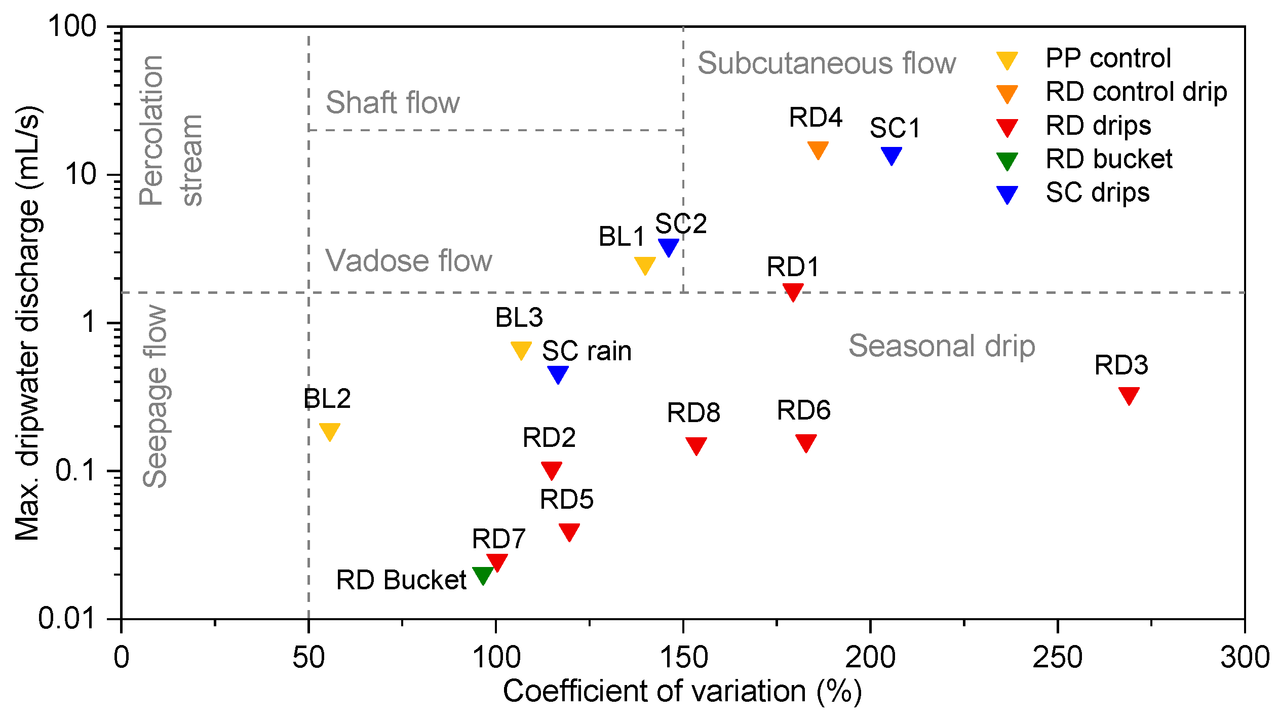
  • PP control—drips scattered across the PP and not reflecting extreme pCO2 conditions (drips BL1, BL2 and BL3);
  • RD control—drip that falls on an actively growing stalagmite (RD4) or a calcite pool near the Red Hall (RD pool);
  • RD—drips (RD drips) or their associated cups (RD cups) located in the most corroded area in the Red Hall (RD1, RD2, RD3, RD5, RD6, RD7 and RD8);
  • RD bucket—drip sampled in the Red Hall without contact with limestone;
  • SC—drips or their associated cups in the SC Hall (SC1, SC2 and the SC stream).
When the text refers to a specific group, it is an average value of all the water samples. Samples of the cup water were collected and filtered with a syringe through a 0.45-μm filter (Acrodisc®, Pall Corporation, New York, NY, USA) into 60-mL airtight HDPE bottles, while the dripwater was first collected in larger acid-washed bottles and then treated in the same way as the cup water. For the determination of solute concentrations, the water samples were filtered into 15-mL centrifuge tubes. SEC and pH were measured immediately before sampling using a portable multiparameter metre (WTW MultiLine® Multi 3620 IDS, Xylem Analytics, DE, Weilheim, Germany) with corresponding probes for measuring the pH (WTW SenTix® 940, Xylem Analytics, DE; accuracy ± 0.004) and SEC (WTW TetraCon® 925, Xylem Analytics, DE; resolution 1 μS/cm, accuracy ± 0.5% of reading and compensation at 25 °C), both calibrated in the laboratory before each sampling trip. Both probes are equipped with temperature sensors (accuracy ± 0.1 °C). The pH probe was kept in a KCl solution and washed with deionised water before use. Washing with deionised water was repeated after each completed measurement.
The temporal dynamics of the hydrochemistry in the cups were recorded by two conductivity loggers with a resolution of 10 min (HOBO U24-001, Onset Computer, Bourne, MA, USA; accuracy ± 5 μS/cm). The loggers were immersed in two cups: the RD conductivity cup (RD Cond. for 3.5 years) and the RD7 cup (for 1 year). With compensation up to 25 °C, the specific electroconductivity (SEC) was obtained, and the drift was corrected regularly by manual measurements with the calibrated handheld device WTW MultiLine® Multi 3620 IDS. In cases when the cups were dry, erroneous data were removed from the total dataset.

2.6. Analytical Methods

The chemical analyses of the water samples were carried out in the laboratory of the Karst Research Institute ZRC SAZU (IZRK) in Postojna and included the measurements of the alkalinity, total hardness, calcium hardness and the concentration of major aqueous species. Carbonate alkalinity (Alk) was determined by potentiometric Gran titration with a standardised 0.02-M HCl. All samples for alkalinity were analysed within 48 h of sampling and stored in a refrigerator prior to analysis. Total and calcium hardness were determined by complexometric titration with 0.01-M EDTA using different buffers and indicators. The Mg concentration was obtained as the difference between the two hardness values. The samples from March 2020 were titrated with the TitroLine® 7800 automatic titrator (SI Analytics, Xylem Analytics, DE) using pH probe A 162 IDS for the alkalinity and calibrated before each use.
Initially, the concentrations of the major ions were determined using Shodex YK-421 ion chromatography (IC) in the laboratory of the University of Nova Gorica, Slovenia. However, due to unexpected difficulties with the instrument, the results were erroneous and unusable. In order to be able to use the quantities measured or analysed with other techniques, such as the alkalinity, the Ca concentration was estimated using a strong linear correlation with the SEC, which is discussed in the results. In 2021, the samples were analysed for the concentration of the major ions using the ion chromatograph Metrohm Eco IC, located in the laboratory of Karst Research Institute ZRC SAZU. The ion chromatograph consisted of two units for anion (Metrosep A Supp 17 anion column, Metrohm, CH, Herisau, Switzerland) and cation exchanges (Metrosep C 6 cation column, Metrohm, CH) with a self-regenerating suppressor. The concentrations were determined with a conductivity detector and calibrated with standard ion solutions. The determined ions were: Ca2+, Mg2+, Na+, K+, NH4+, Li+, Cl, F, Br, NO3, NO2, SO42− and PO43−. In the analysed samples (n = 18), Li+, PO43−, F and Br were below the detection limit.
The derived hydrochemical parameters (saturation index with respect to calcite (SIcc), pCO2(eq) and pCO2(sat) (pCO2(eq) value of water with SIcc = 0) for forward and backward mass balance modelling were calculated using speciation software PHREEQC [31]. The input parameters included the pH, alkalinity, ion concentrations and temperature. The samples that had a charge balance of >5% were discarded for further evaluations. Overall, 89% of the samples were within a 5% and 98% within a 10% charge balance error.

3. Results

3.1. Bedrock Chemistry

The results of an elemental analysis of rock samples containing corrosion cups are given in Table 1. The composition of the bare rock samples (Rock #1–#4) is typical of pure limestone, while, in the flowstone samples, there is a marked depletion of Mg and Sr and similar values for other trace elements. The red flowstone sample has a higher proportion of trace elements (Na, K, Fe, Al and Si) than the yellow flowstone samples. The concentrations of Ba and Mn were below the detection limit (<0.001 ppm and <0.0001 ppm, respectively). These results are comparable to previous chemical analyses of rock or sediment samples in Pisani Passage [44].

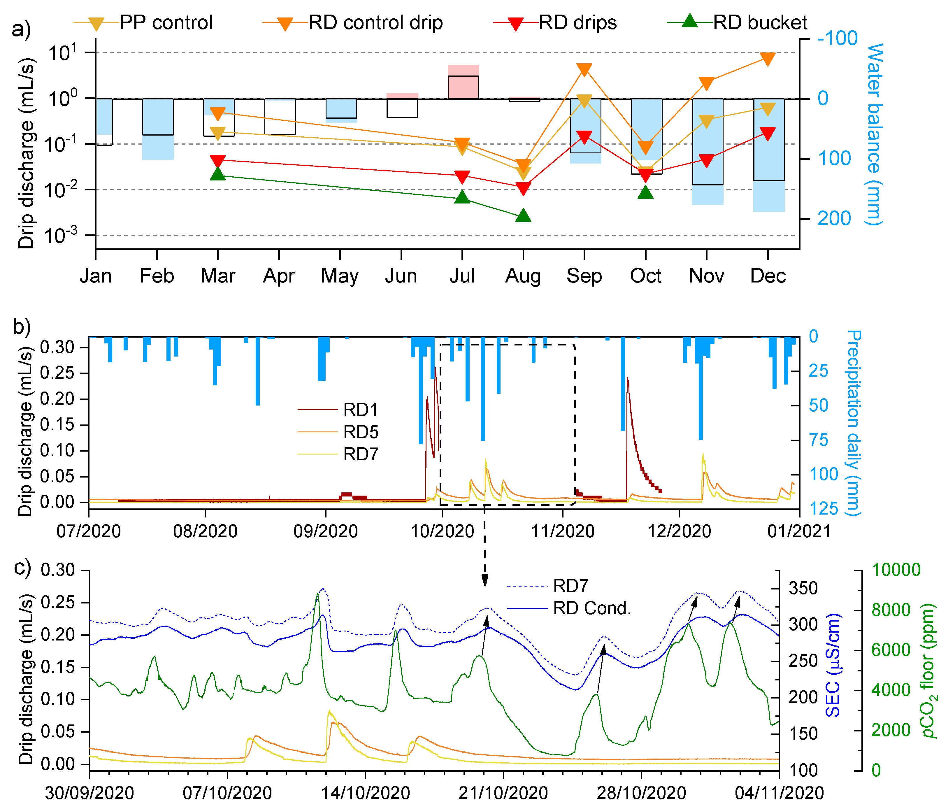
3.2. Dripwater Hydrology

According to the drip hydrology classification of Baker et al. [45], most of the sampled drips belong to the “seasonal drips” category, while a few others belong to the “subcutaneous flow” or “seepage flow” groups (Figure 5). In the Red Hall, RD1 and RD4 show the greatest variations and the highest discharge rates, but such drip sites are usually rare. The control drip BL2 showed the highest stability of discharge. Storm events were recorded at virtually every site, and the responses depended on the previous saturation of the vadose zone (Figure 6a,b [46]). Figure 6b shows the responses to precipitation at some continuously monitored drip sites (RD1, RD5 and RD7), while Figure 6c compares the drip discharge with continuous variations in the SEC in cup water and pCO2 in the cave air near the floor.
During the monitoring period 2017–2020, the mean annual precipitation was 1596 mm, close to the climatic mean (1500 mm). Precipitation was concentrated in the cooler period, with the wettest months of September, November and December receiving 125% of the usual (climatic) precipitation, while the three driest months of January, March and April receiving 80% of the usual amount (Figure 6a). The dripwater discharge followed the seasonal trend of precipitation, with the highest discharges occurring in the wetter, cooler months (especially autumn), when the water excess is greatest. In the summer (June–August), all monitored drips in the Red Hall, except RD4 (RD control drip), dried or became very slow (~2 drips/min), which was the main limiting factor for sampling during this period. The longest period of above-average precipitation was the winter 2017 to 2018 (November 2017–April 2018; 38% more precipitation over this period) exactly during the first and most frequent water sampling trips.

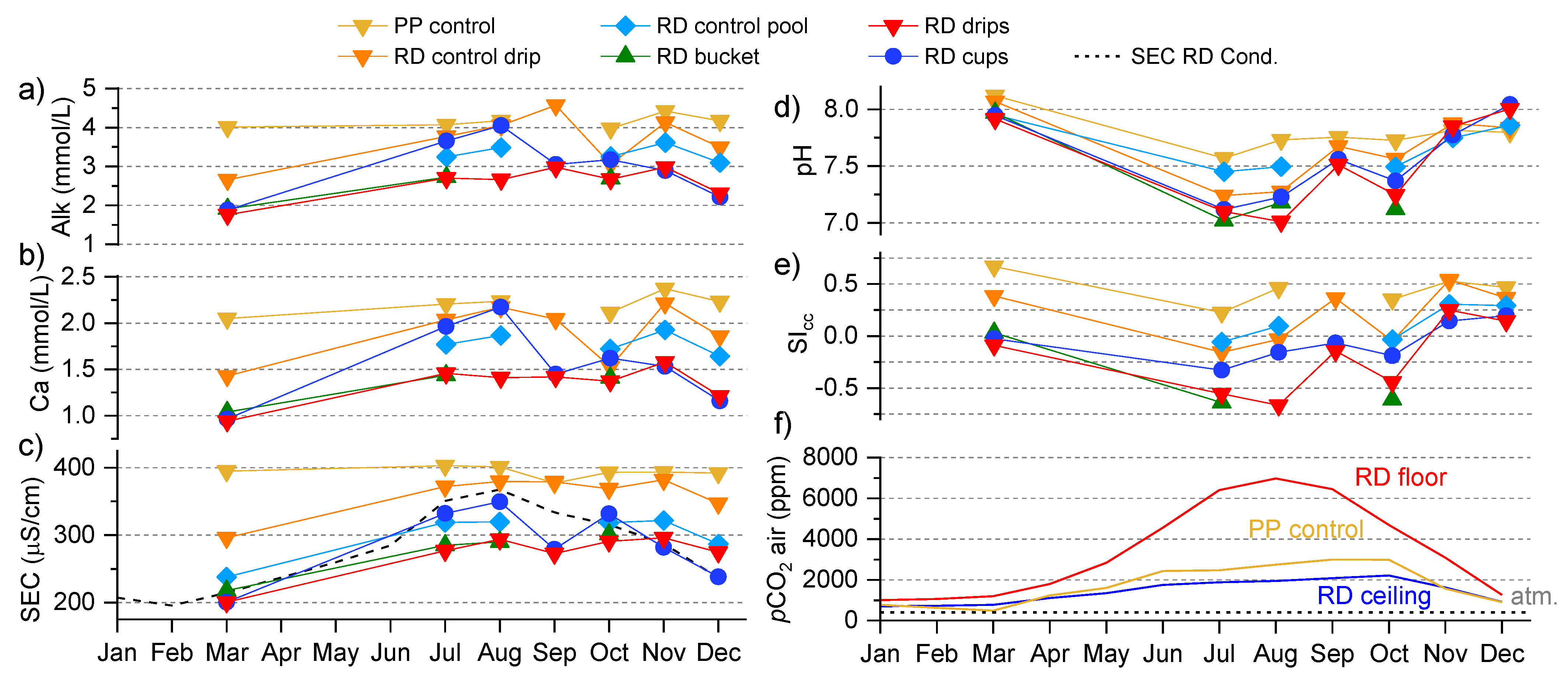
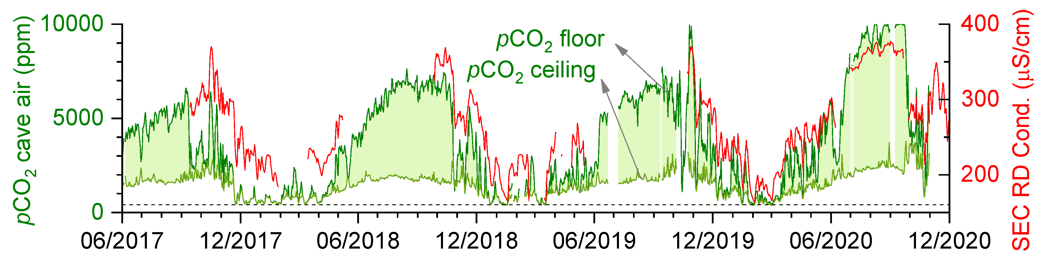
3.3. Spatiotemporal Dynamics of CO2

The spatial and temporal CO2 dynamics in Pisani Passage were investigated in a previous study [15], while only the results relevant to the geochemistry of the dripwater are reviewed here. The CO2 dynamics follow the seasonal airflow pattern for Postojna Cave, with the highest pCO2 values measured during warm periods (July–September) when the downdraft prevailed and the lowest in cooler months (December–February) during the updraft, when the values often approached those outside (Figure 7). In the cooler periods, air moved through large airflow pathways (direction from the main entrance towards PP), while, in the warm periods, the air was directed from the soil and the vadose zone with high pCO2 to the interior of PP (see the airflow direction in Figure 2a). High CO2 conditions in the winter occurred only exceptionally when NE winds forced the ventilation direction into a downdraft and lasted only for a short time [47]. In Pisani Passage, the pCO2 values gradually increased from about 1000–2000 ppm to about 3000–4000 ppm from the entrance toward the farthest extent. The greatest increase in pCO2 was found in the lowest floor sections of the Red and White Halls at the end of Pisani Passage (Figure 2b). In a location where the air was sheltered from ventilation and mixing, a pCO2 value of 12,640 ppm was measured, which was not only the maximum value for Pisani Passage but also of Postojna Cave. Due to the different characteristics and positions of the airflow pathways, the air in the Red Hall was stratified, with pCO2 values near the floor showing ~6000 ppm higher values than at the ceiling in extreme cases. This contrast is illustrated by the 2017–2020 time series in Figure 7 with green shading. The stratification of the air was supported by a downdraft, while an updraft mixed the air and homogenised the distribution of CO2 [15].

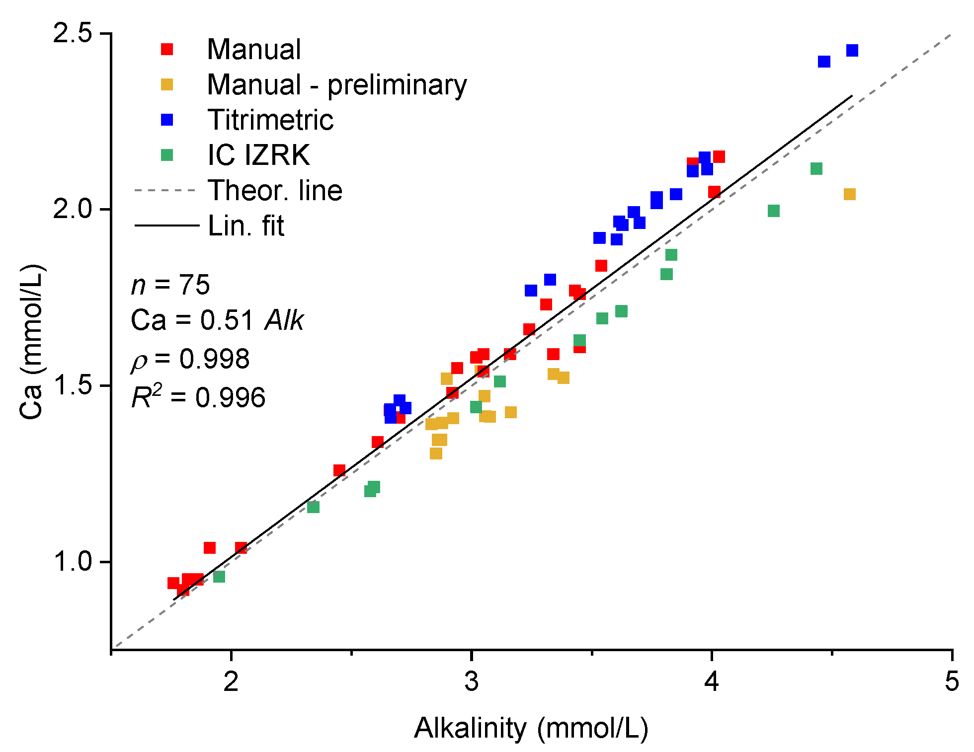
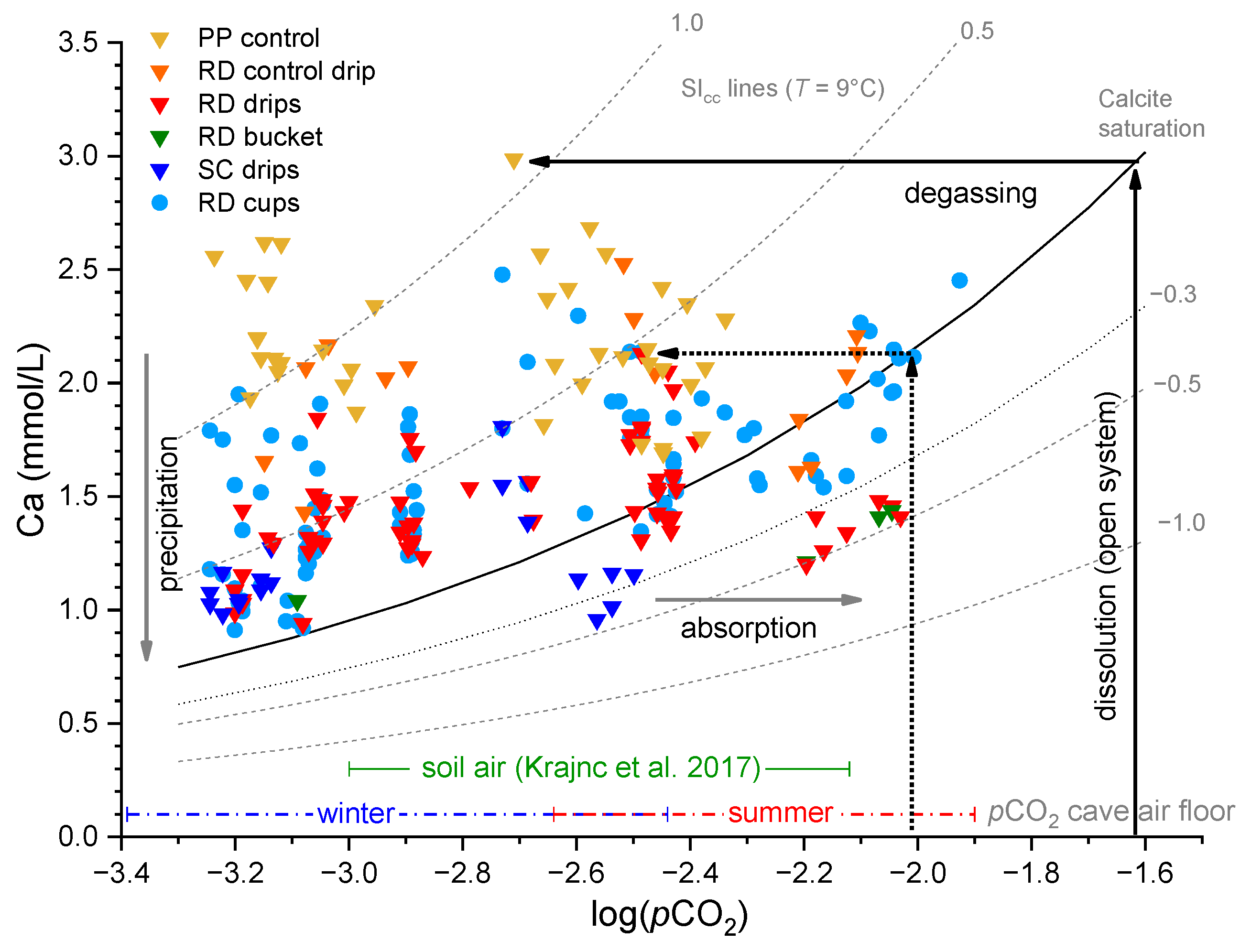
3.4. Drip and Cup Water Chemistry

As mentioned in the Methods section, most of the samples analysed using the Shodex YK-421 IC gave erroneous major ion concentrations. In order to be able to use the data nevertheless, the Ca concentrations were calculated using a strong linear relationship with alkalinity that was determined by a separate method (i.e., potentiometric titration). The relationship is shown in Figure 8 and was evaluated by the Pearson factor ρ (0.998) and the coefficient of determination R2 (0.996). The linear relationship was also consistent with the theoretical line, confirming that the sampled waters were predominantly the Ca-HCO3 type. The Mg concentrations showed a weak correlation with alkalinity, so a constant value of 0.04 mmol/L was used, which was the mean value of the Mg concentrations determined in the subsequent analyses. The possible fluctuations and deviations of Mg from this value proved to be insignificant for the further interpretation of the results, and previous studies confirmed that this was a reasonable estimate [41].
The time series of the alkalinity, calcium concentration, SEC, pH, SIcc and pCO2 of the cave air were summarised as collated monthly averages over the period 2017–2020 (Figure 9). The parameters showed general seasonal variations with a few exceptions (see Discussion in Section 4.2.1). In the cooler months, the dissolved ion concentrations (Alk, Ca and SEC) were the lowest, while the pH and SIcc values were the highest. In the warm summer months, the samples had higher solute loads (alkalinity, Ca and SEC) and a wide range in SIcc (from −0.5 at RD to 0.5 at the control sites). The control drips were the least variable, showing almost constant values for the Ca, alkalinity and SEC but minor fluctuations in the pH and SIcc. The SIcc values of the control drips never fell below zero. The average value of the alkalinity was highest in the control drips at PP (4.3 mmol/L) and much lower in the RD drips (2.8 mmol/L). Similar extremes were found for the Ca concentrations (2.2 mmol/L for the control group and 1.5 mmol/L for the RD drips) and SEC (from 389 μS/cm to 291 μS/cm). Differences between the RD drips and controls occurred throughout the year, regardless of the season, which was already observed in a previous study [41]. When comparing the RD drips and cups, the differences in the aqueous species were minimal in the cooler months and maximal in the summer (July to August). The dripwater temperatures ranged from 8.7 °C to 9.1 °C, while the average water temperature in the cups fell within these values (8.9 ± 0.2 °C), which was again very similar to the average air temperature in RD (8.8 °C) [15].
The continuous time series of the RD Cond. cup water SEC closely followed the manual measurements in other cup waters, which was confirmed by a high linear correlation (ρ = 0.995, R2 = 0.990). A similar high correlation was found in the case of the neighbouring RD7 cup (ρ = 0.999, R2 = 0.997; also shown in Figure 6c). A high correlation was found between the SEC and pCO2 (already shown in Figure 7). Any change in pCO2 was quickly reflected in the water chemistry, which could also be seen in the moderate correlation between the log(pCO2) and SEC and pH (Figure 10a,b). The linear correlation between the Ca concentration in the water samples and SEC was strong (Figure 10c, ρ = 0.888, R2 = 0.785), which was very similar to the correlation from the global dataset for clean carbonate water [48]. The linear relationship of the SEC with the alkalinity of the water samples was also strong (Figure 10d; ρ = 0.912, R2 = 0.830). A high correlation of Ca or alkalinity to the SEC is expected in Ca-HCO3-type water, as these two ions account for a major proportion of the dissolved species. The mean values of the aqueous parameters (alkalinity, Ca concentrations, pH and SEC); their variations and correlations from Figure 10 are in agreement with previously published results [41,49].

4. Discussion

4.1. Origins of Undersaturated Dripwaters

4.1.1. Geology

One of the plausible explanations for the increased dissolution in the Red Hall is a possible dissolution of limestone due to impurities, which could cause increased acidity in addition to the usual dissolution by carbonic acid (e.g., pyrite). The results of the elemental analysis of a single rock block with a corrosion cup (Figure 4) are given in Table 1 and indicate that this is not the case. The rock is composed of pure limestone, typical of the lithology of Pisani Passage, as it likely derives from a breakdown of the host rock. The analysis of the flowstone covering the rock sample revealed a similar composition with a depletion in Mg and Sr concentrations [44]. Considering the vadose zone that determines the chemistry of the percolating water, the lithology is not expected to differ over the extent of the cave to the surface [34]. Our results and previous dripwater analyses carried out at Pisani Passage show that the dripwater is of the Ca-HCO3 type characteristic of water percolating through pure carbonate karst [44]. We might expect a greater influence on the water chemistry at the SC Hall, where dolomitised limestone and chert lenses have been detected [38,50,51]. However, our hydrochemical results, which we present in the following sections, do not support this assumption either.
More interestingly, the rock overburden above Pisani Passage has a variable thickness, with the greatest cover at the entrance (~100 m), gradually decreasing to 50 m above the SC Hall and to 30 m above Red Hall as the passage approaches the Jeršanova Doline, which terminated the course of the passage to the north [35,50]. Many hydrochemical parameters of the sampled drips show a trend related to this reduction in the thickness of the rock overburden along Pisani Passage, which is explained in more detail in the following sections.

4.1.2. Soil and Vadose Zone Conditions

To explore the possible origin of the undersaturated dripwater, backward modelling of the water chemistry could provide an estimate of the pCO2 in the vadose zone before the water equilibrates to the cave conditions. However, this value will always be an underestimate due to the possibility of PCP, incomplete saturation, closed system conditions or incomplete soil cover [28,29,52]. In a diagram showing the relationship between the Ca concentrations and log(pCO2) (Figure 11), it is clear that the different drip groups occupy different areas. In general, the control drips have higher Ca concentrations than the drips causing corrosion, while the Ca concentrations of the corrosion cup waters tends to lie between these two groups. Under the open system conditions, the maximum possible pCO2 value of the water in equilibrium with the gas phase (i.e., pCO2(eq)) for the control group of drips was about 10−1.6 (~25,000 ppm; black arrows), while the minimum value for the same group was about 10−2.2 (~6300 ppm). For the RD cup waters and corresponding drips, the maximum value was found to be 10−2.0 (~10,000 ppm; black dashed arrows), while the minimum value was 10−3.1 (~800 ppm), but such low values tend to indicate strong degassing in the cave before collection, usually in the winter. The highest Ca concentrations were thus be explained by the parent solution being in contact with the highest pCO2 of the vadose zone, as was found to be the case with the PP control group.
Monitoring the soil pCO2 may provide another boundary for evaluating the formation of initial dripwater chemistry. The only such study to date, where the monitoring setup was located at the surface directly above the Red Hall, was conducted by Krajnc et al. [40] in 2014 to 2015. There, it was found that the seasonal dynamics of pCO2 and δ13CO2 in the soil at different soil depths (20–80 cm) were promoted by cave ventilation, in contrast to the typical factors of the soil temperature and soil water content that determined the soil CO2 production at a nearby control site. The pCO2 value in the soil ranged from 1000 to 7600 ppm, which was lower than the maximum value measured in the cave (10,426 ppm; the pCO2 range in the soil air is marked by a green line in Figure 11). However, the measured pCO2 in the upper soil layer could be an underestimate compared to a subsoil CO2 reservoir that likely contributes much CO2 to the cave. In addition, studies have shown that the deeper vadose zone may in fact be a larger source/reservoir of CO2 than the soil and epikarst, where the greatest biogenic CO2 production would usually be expected [8,28,53,54,55]. Accordingly, the high CO2 zone, in our case, seemed to be shifted even deeper into or below the cave itself [15]. Furthermore, the soil cover was not found to be an important factor in determining the water chemistry across PP, as it did not vary across the extent of PP on the surface [52]. The surface cover was generally uniform, with rocky soils in the forested area.

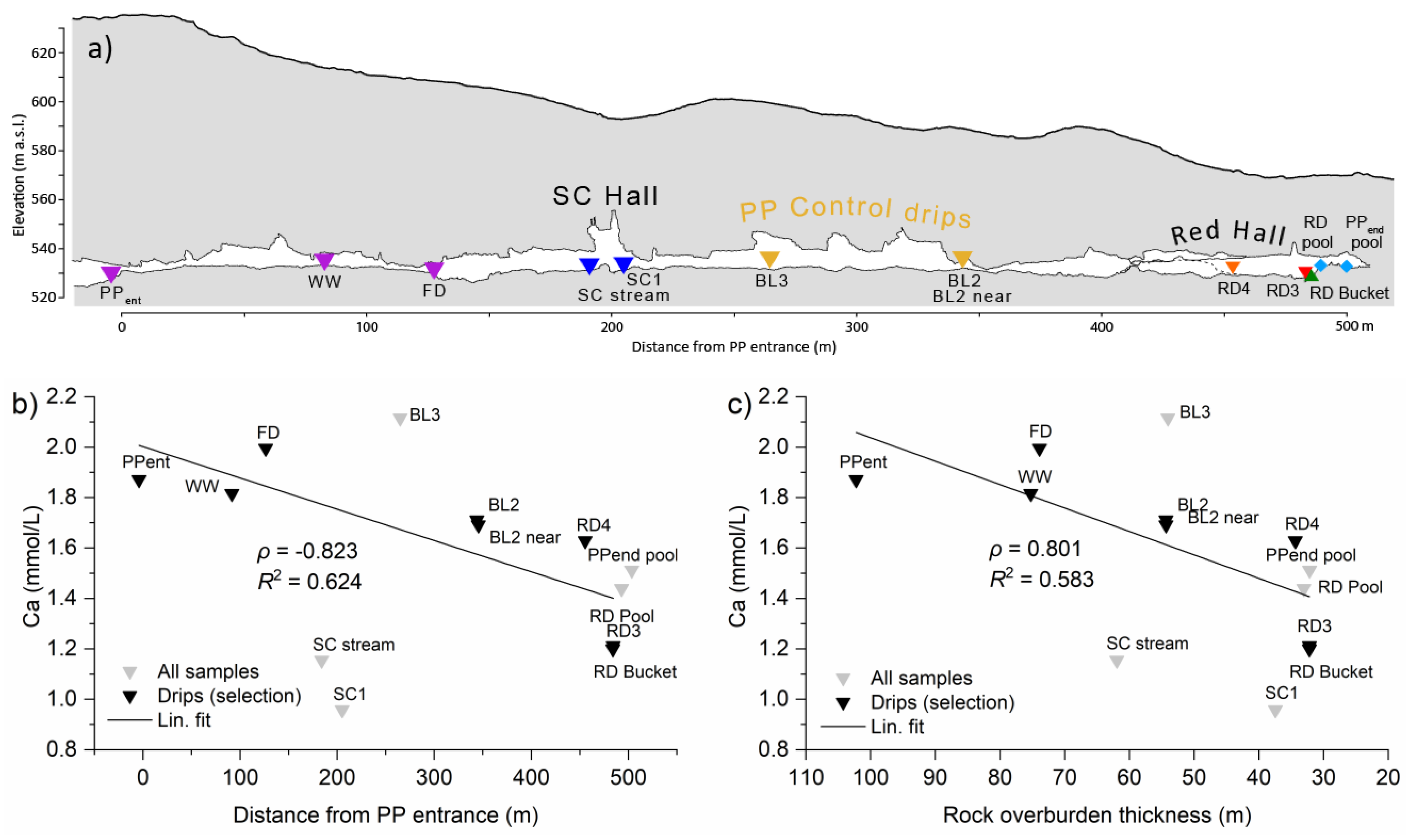
4.1.3. Thickness of the Rock Overburden

Comparing the results of the different sampling groups in Figure 11 with the morphology of PP (Figure 2b), there appears to be a negative trend between the Ca concentration and distance from the PP entrance. The geochemical profile in Figure 12a shows that this trend could be related to the thickness of the rock overburden, which, as mentioned earlier, decreases from the entrance to the end of PP. To confirm this influence on the initial dripwater chemistry, we sampled additional water samples across PP on 14 July 2021 (Figure 12b,c). The Ca concentrations of the dripping waters decreased with the distance from the entrance of PP or with the decreasing thickness of the rock overburden. The Ca concentrations of the dripwaters decreased from about 2 mmol/L measured near the entrance of the passage to as low as 1.2 mmol/L in the Red Hall. The exceptions were in the SC Hall, where the lower Ca (<1.2 mmol/L) was probably due to a more direct connection to the surface, and in BL3 with a higher Ca concentration (>2 mmol/L), perhaps due to the much longer water pathways. The correlation was moderate but surprisingly high when considering all the possible factors that could influence the water chemistry (e.g., varying pCO2 in the soil or vadose zone, water flow pathways, airflow pathways and open or closed system conditions).

4.2. Processes Occuring in the Cave

4.2.1. Dripwater Entering the Cave Atmosphere

The drip discharge is greatest in the cooler months—during periods of increased water excess (Figure 6a) and shortly after heavy precipitation events (>20 mm/day; Figure 6b). In the warm months, many of the drip sites in the Red Hall dry up or reduce to constant low drip rates of about 2 drops per minute and do not respond to precipitation events. For two of the longest available time series of drip counts, a moderate correlation was found between discharge rate and water balance on a monthly basis (R2 = 0.537 for RD5 and R2 = 0.644 for RD7). This behaviour can be explained by the saturation of the vadose zone, which replenishes during the cooler period and depletes during the warm period when the evapotranspiration increases [1,56]. In the Red Hall, only a small percentage of the drip sites show fracture-fed seepage (e.g., RD1 in Figure 6b), while the majority of the drips are fed by the slow-draining matrix component (Figure 5). After precipitation, the majority of the RD drips show a sharp increase in SEC (Figure 6c), a response that contrasts with the rapid fracture-fed sites, where a decrease in the SEC and undersaturation with respect to calcite is probable. However, the variations in the SEC correlated more with changes in the pCO2 in the cave air than with hydrology (see the time series in Figure 7 and the correlation in Figure 10a). This was also true for SIcc, which correlated only weakly with the drip discharge. Compared to the RD drips above the corrosion cups, the PP control drip group showed lower annual fluctuations in the drip discharges, stable water chemistry with an almost constant SEC and generally higher solute concentrations (Figure 9). All PP control drips had positive SIcc values throughout the year, with the maximum occurring in the winter (Figure 9e). Such behaviour of these sites could indicate efficient buffering of the outside signal, which could be related to the thicker overburden above these sites than above the Red Hall.
We now discuss whether the kinetics of the reactions involving carbonate species could play an important role in determining the geochemical conditions in the Red Hall. The initial degassing of dissolved CO2 from the solution occurred within seconds, while the subsequent equilibration with an increase in pH and SIcc was an order of magnitude slower as HCO3 was converted into CO2 [30]. Therefore, slow drips with drip intervals longer than the initial degassing phase would be most likely equilibrated to the low pCO2 at the ceiling level and achieve the greatest supersaturation. However, without further precipitation at the ceiling, no change in the calcium concentration can be expected between a drip sampled at the ceiling and a drip sampled near the floor. Only very slow drips (drip intervals in the range of ~400 s) would exhibit precipitation (i.e., PCP). None of our samples showed such slow drips, not even during the dry summer periods. From a visual inspection of the ceiling, we concluded that precipitation does not readily occur at the ceiling. However, PCP could be important, as many of the geochemical parameters resulting from this process were found in our data (low SEC, low SIcc and low mineralisation [27,57]). However, to diagnose PCP, at least the ratios of the trace elements (e.g., Mg/Ca and Sr/Ca) and the δ13C signature would need to be determined, with higher values being a key signal for this process. Alternatively, mixing corrosion could provide a source of potential dissolution in the Red Hall [57]. However, both mixing corrosion and PCP in the vadose zone are highly unlikely to control the geochemistry in our case, as there is simply an abundance of corrosion features over a wide area fed by several hundred different drips.

4.2.2. Dripwater Evolution in the Cave

The dripwaters that emerged at the control sites of PP and RD almost always originated from an atmosphere with similar or higher pCO2 than in the cave. This is illustrated in Figure 13 by the monthly variations of pCO2 in the cave air and pCO2(sat) in the water (pCO2(eq) of the solution forced to SIcc = 0). The maximum value of pCO2(sat) obtained for the controls from RD was close to the maximum value measured in the cave (~12,000 ppm). In contrast, the RD drips above the corrosion cups appeared to have lower pCO2(sat) values than the cave air pCO2 value, especially in the warm period (July–September), as indicated by the red shading in Figure 13. In the period of July to August, such a geochemical situation was also observed at the sites in the SC Hall. Interestingly, none of the drips, either RD or the controls, showed a stability of pCO2(sat) but showed a similar seasonality as the pCO2 of the cave air. One of the reasons could be that the dominant sources of CO2 are located in the soil zone and epikarst, where the surface conditions vary with the seasons and hydrologic conditions. Another explanation could be the strong degassing along the water flow paths and the possibility of PCP, either in the vadose zone or at the ceiling. In the vadose zone, this could be possible due to upward cave ventilation in the winter, which effectively flushes out some of the biogenic CO2. At the ceiling, it could be possible if drips do not fall directly on the stalagmite but flow along the outside of the stalactites or along the cave walls and even more so if the drip interval is long [27,30,58]. However, the ceiling of Pisani Passage is not overly occupied by stalactites, especially not the Red Hall, which limits the importance of PCP.
The range of estimated pCO2(sat) values at Red Hall is consistent with a recent study in which the pCO2(sat) value of dripwater sampled at Pisani Passage near RD (8710 ppm) was the lowest of all the drip sites studied at Postojna Cave, although the highest pCO2 value of cave air was measured there [32]. Using the data published by Vokal et al. [49] for the measurement site in the SC Hall, we again calculated a similar range of pCO2(sat) as in our control or SC measurements (2800–5500 ppm).
In Figure 14, which compares the dripwater SIcc with the log(pCO2) values, the majority of the drip groups lie along the CO2 degassing or absorption lines (slope ~−1), assuming a possible wide range of pCO2(sat) between 10−3.0 (1000 ppm) and 10−1.8 (~16,000 ppm), and are assumed to originate from parent solutions with SIcc = 0 [58]. The scatter between the sites can be explained by different water flow paths and varying conditions in the vadose zone and PCP. As expected, the highest calcite saturation (~0.8) was reached in the control group. The RD drips reached SIcc ≈ 0.6 only in the cooler months, while above a cave air pCO2 value of 10−2.2 (~6300 ppm), they exclusively showed undersaturation.

4.2.3. Mechanism of Cup Formation

Seasonal cave ventilation, driven by the chimney effect, controls the temporal dynamics of pCO2 in the cave air [15]. The clearest link between pCO2 in the cave air and water chemistry comes from records of the SEC (as explored in detail in Reference [59]). The continuous time series of the SEC measured in the RD Cond. cup showed a high similarity with all the other manually measured SEC values in the Red Hall (see red dots in Figure 10a), resulting in a high correlation coefficient (ρ = 0.995, R2 = 0.990). Thus, although fed from different infiltration pathways, the differences in the SEC were small when comparing different cups within a given time period. Moreover, the cup water SEC showed a very high similarity with the variations of pCO2 in the Red Hall (Figure 7 and a closer view in Figure 6c). Although the Red Hall is characterised by a vertical gradient of pCO2 in the air, the pCO2 at the floor level—where the cups are located—is uniform, with little horizontal variability [15]. The continuous time series of pCO2 of the cave air at the floor station, therefore, strongly reflects the pCO2 conditions prevailing in the area of cup formation, while the similarity with the values of SEC suggests a controlling role (as seen in Figure 10a; ρ = 0.901, R2 = 0.811). As the pCO2 in the air increases, some CO2 dissolves in the solution, dissolving the cup wall and forming ions that increase the SEC. Conversely, as pCO2 falls, the water equilibrium shifts back, releasing gaseous CO2, precipitating calcite and causing the SEC to fall. In this way, the seasonal fluctuations in pCO2 imprint a similar variation in the SEC of the cup water, with low values in the winter (~200 µS/cm) and high values in the summer (~300 µS/cm). The response of the pCO2 fluctuation to the chemistry of the cup water is consistently visible up to an hourly scale. However, the response was delayed by a few hours to about 12 h (Figure 6c). In the inner RD area of corrosion, precipitated calcite crystals are not clearly visible in the corrosion cups, but in the cups in the outer area, even millimetre-sized crystals can grow, as in the case of RD2 (Figure 3d).
Low initial calcium concentrations of dripwaters in the Red Hall and the SC Hall have an important effect on SIcc, as an increase in pCO2 in the cave air tends to undersaturate such drips, especially in RD, where CO2 accumulates [14,16]. This was already illustrated in the theoretical example in Figure 1 by the water evolution from point D to H and was also visible in our case in Figure 11. In the pCO2 range of 10−2.2–10−2.0 (6300–10,000 ppm), there is a clear difference in Ca concentrations between the RD cups (light blue dots) and drips (red triangles), with the cups having concentrations about 0.5 mmol/L higher than the drips. Above a pCO2 threshold of 10−2.2 (~6300 ppm), the RD drips have a SIcc ≈ −0.3, while the RD cups have a slightly higher SIcc ≈ −0.25. Since the RD drips are collected directly above the respective cups, they are equilibrated to the high CO2 conditions prevailing near the cups. When the dripping water comes into contact with the cup walls, dissolution occurs, eventually elevating the SIcc towards zero. The RD bucket shows a similar chemistry to the RD drips in that it is actually a dripwater that is in equilibrium with the pCO2 at the floor but is unable to dissolve calcite (see the RD bucket in Figure 11).
The lowest limit of pCO2 at the floor, where some drips and cups started to become undersaturated, was already at ~10−2.5 (~3200 ppm). Interestingly, the cave air pCO2 values were above this limit exactly 50% of the time during 2017–2020 [15]. The greatest dissolution would be expected in cases where the drips and cups were strongly degassed before the pCO2 value of the cave air increased, as shown in the theoretical example in Figure 1. This could be achieved, for example, during the summer periods with strong airflow reversals that temporarily deplete pCO2 from the cave air but quickly re-establish high CO2 conditions and gradients (see, for example, October 2019 in Figure 7). The RD control drip is less likely to be affected by changes in the cave air pCO2 but shows undersaturation when pCO2 rises above a threshold of 10−2.3 (~5000 ppm). Although high CO2 levels have been found in both the Red and White Halls, large, macroscale dissolution features are only found in the Red Hall, where the dripwaters feeding the cups generally have the lowest Ca concentrations.
In contrast, in the SC Hall, neither strong fluctuations in the pCO2 nor an air stratification phenomenon were found (pCO2 range 450–5100 ppm, average 1800 ppm). There, the ceiling of the SC Hall is much higher than elsewhere along PP, and the drip sources are beyond sight, but many drips come from >50-m-high chimneys, which could progress even further toward the surface. The largest variations in the drip discharge rates and the lowest measured Ca concentrations measured in this study indicate a high proportion of undersaturated fracture flow to the SC Hall drips. Therefore, a high degree of geological and hydrological control is expected, while the cave air pCO2 does not need to be elevated to achieve an undersaturation of dripwater in the SC Hall.

4.3. Dominating Controls

The previously proposed and discussed control mechanisms for the formation of the corrosion cups in the Red Hall are now summarised, and the main arguments are further elaborated:
(1)
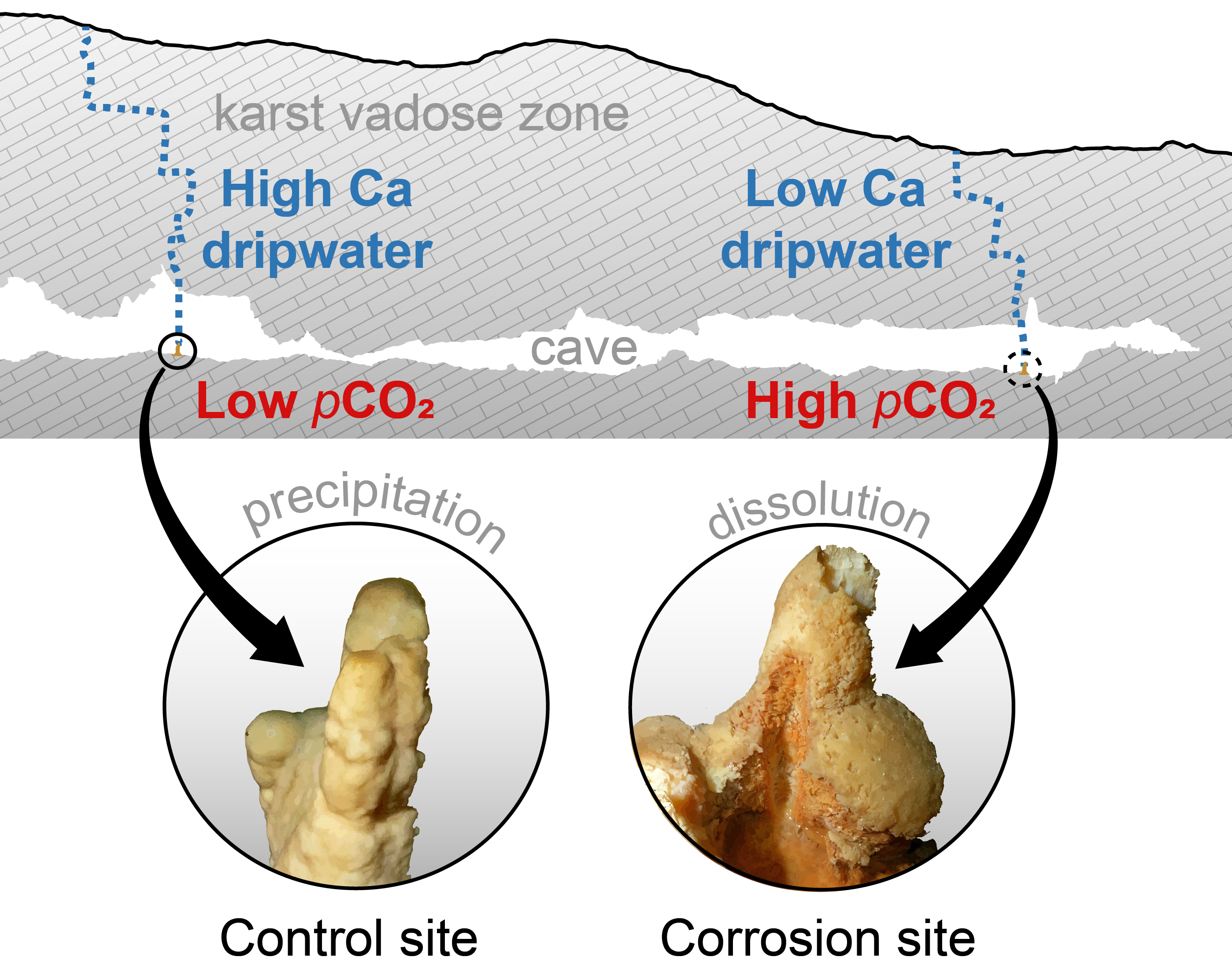
The rock overburden becomes thinner towards the end of Pisani Passage, and the Ca concentrations of the dripwaters are lower in the Red Hall than at the control sites. When the dripwater Ca concentrations are low, the pCO2 of the cave air can more easily modulate the calcite saturation state towards undersaturation.
(2)
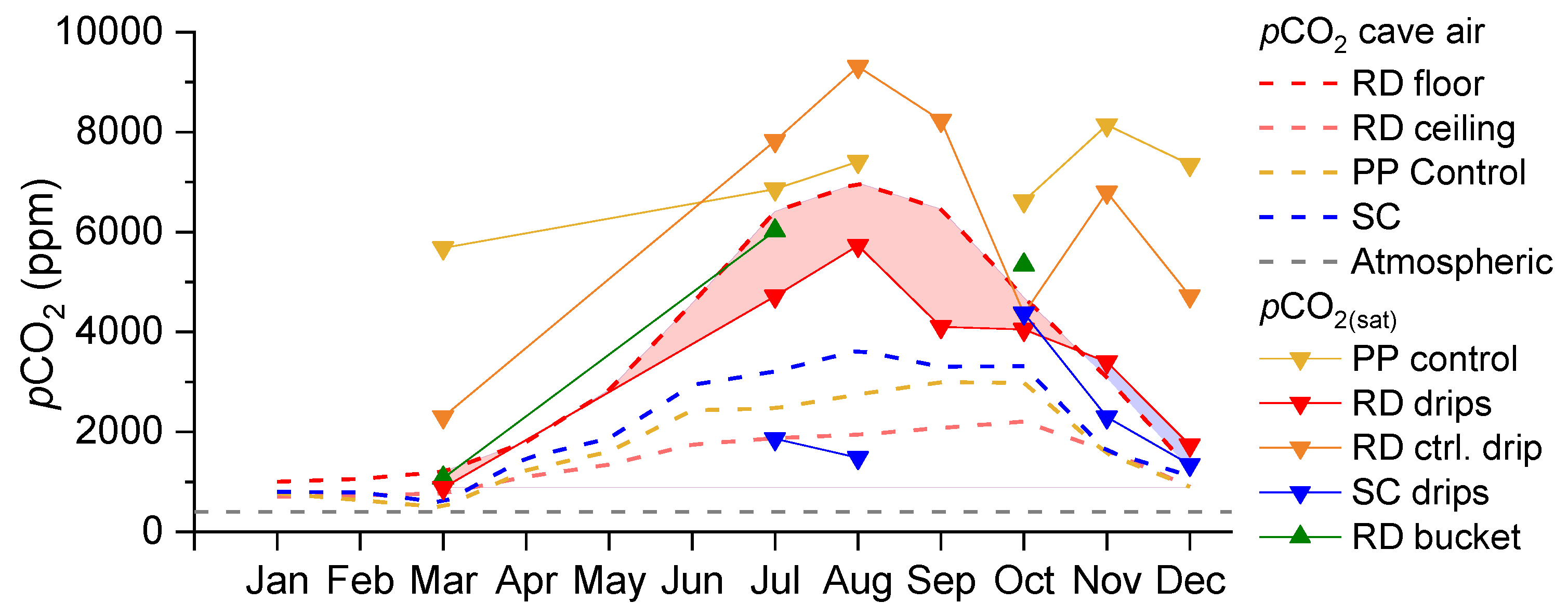
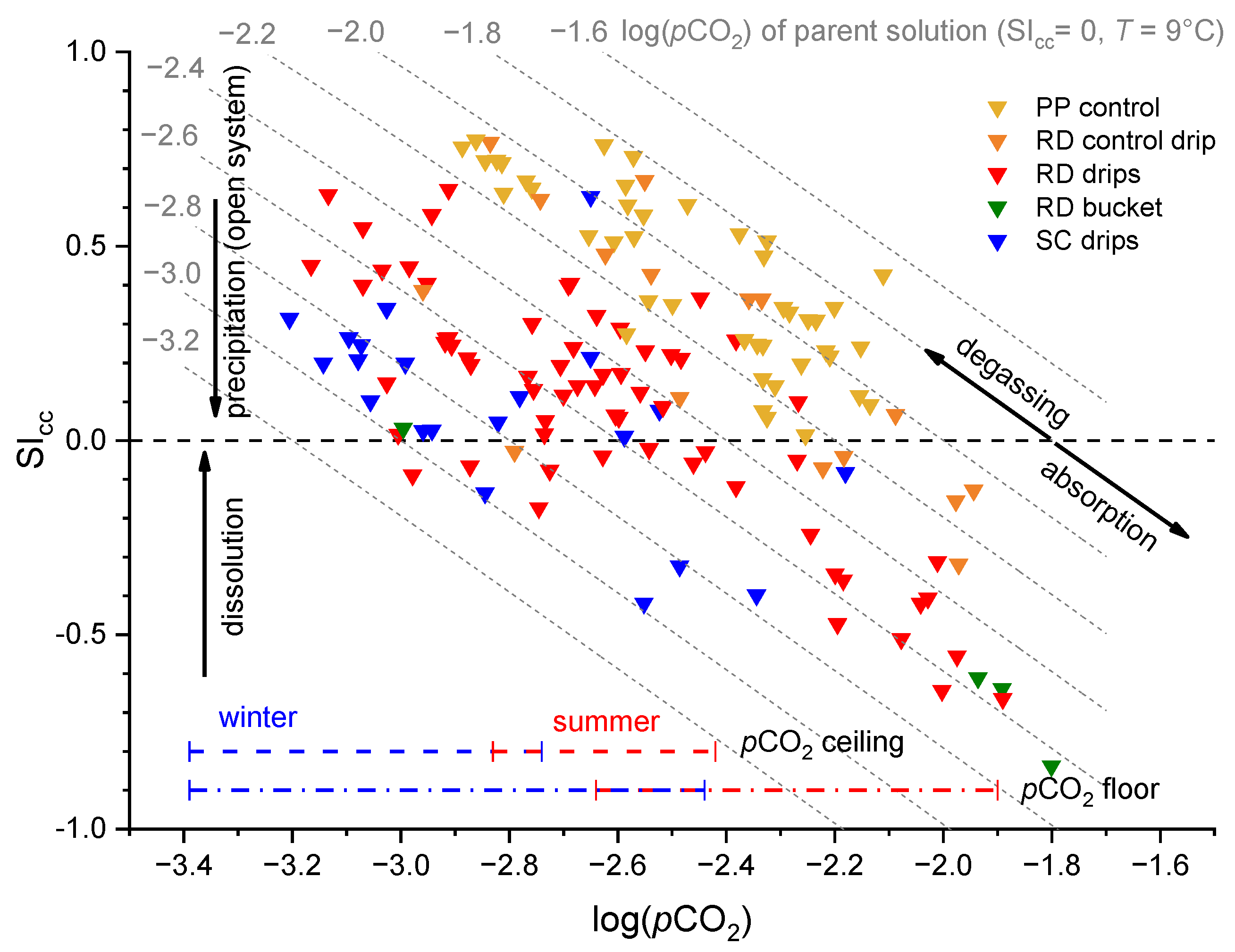
In warm periods during the downdraft, the floor of the terminal section of the Red Hall is sheltered from advection, which promotes CO2 accumulation, while the ceiling is in an efficient ventilation pathway [15]. In such an environment, the dripping water near the ceiling can easily degas, but more importantly, the CO2 is absorbed near the floor. The estimated pCO2 of the percolating water in the vadose zone (i.e., the pCO2(sat)) was always lower than the air pCO2 measured at the cave floor during warm periods. Such a contrast causes dripwater at the cave floor to become undersaturated, which promotes the dissolution of calcite and the formation of corrosion cups.
(3)
The degree of dissolution is controlled by both the hydrological conditions of the vadose zone and the conditions of the cave air. While high pCO2 values regularly occur in the late summer (July–September), dripwater discharge is usually lowest at this time. In the winter, this behaviour is reversed; the pCO2 value is low, and the discharge rate is increased. In intermediate periods such as the autumn or when there are rapid short-term changes in the pCO2 of the cave air, the fluctuating pCO2(eq) of the water could be the most important factor for the increased dissolution in the corrosion cups.
As for the second and third points, the Ca concentrations of the RD drip waters, which fed the corrosion cups, varied only slightly within a year (1.5 ± 0.2 mmol/L), which means that the variations of the dripwater SIcc are mainly influenced by the variations of the pCO2 of the cave air. Of course, the highest dissolution is expected in the warm summer, but in parallel, the dripwater discharge becomes the limiting factor. Since dripping is increased in cooler periods, we would assume that late summer (still warm, downdraft ventilation and high pCO2) and early autumn (increased saturation of the vadose zone) are the periods with the most intense dissolution. This is likely to be true to some extent, as our data showed, for example, that the onset of a wet period quickly dilutes the cups with fresh water, regardless of the high pCO2 in the cave air. This could be seen in Figure 9e for the RD cups in September, when the SIcc increases with the increasing precipitation (rainfall). The pre-summer dissolution is probably most intense in the spring, when the water contained in the cups is most degassed and the Ca concentration in the dripwater reaches a minimum, so the pCO2(eq) change is the greatest with the onset of the summer downdraft and the increase in cave air pCO2. Further research is needed to better constrain the timing of dissolution and its hydrological control through more frequent sampling and measurements of the drip rate during a single hydrological year.
The question remains, do the proposed controls stand the test of time? The corrosion cups, now covered by a layer of flowstone, show that these controls are susceptible to changes in certain conditions that must have persisted over long periods of time to exhibit such a clear outcome. While changes in the overburden may be disregarded, changes related to weather or climate that determine the conditions in the vadose zone and karst underground could be of utmost significance. For example, warmer outside temperatures would enrich the CO2 sources in the upper layers of the vadose zone (soil and epikarst) and, in turn, enrich the dripwaters with calcium, provided water availability [52]. However, warmer outside temperatures would also allow for a stronger downdraft and longer periods of high pCO2 that promote dissolution and weaker updrafts during cold periods that promote precipitation. Across seasons, the overall precipitation of calcite could be favoured by drier summer periods and wetter cold periods. In any case, the extent to which these control mechanisms, their interrelationship and possible feedback loops determine the formation of flowstone-covered corrosion cups needs further study.

4.4. Dissolution Rate Estimates

The hydrochemical results and the comparison with the cave air dynamics revealed the main controlling mechanisms and the temporal dynamics of the corrosion cups formation, but there are still no answers to their formation rate or age. In addition to the hydrochemical arguments presented earlier, we now present further steps to obtain quantitative estimates of the dissolution rate.
To detect active dissolution and precipitation on a short temporal scale, Johnston et al. [60] used specially designed, finely polished limestone tablets left under exposure in Pisani Passage in either cup water or under an active drip spot for various periods of time. The changes on the surfaces of the tablets were observed by scanning electron microscope (SEM), while the precipitation or dissolution rates were obtained by stereoscopic imaging and 3D analysis. For example, the tablet immersed in the RD5a cup (cup adjacent to RD5) showed pronounced surface etching under exposure for 28 weeks (7 months), which included the summer period of 2018 (March–October). The dissolution rate was calculated to be 0.01–0.025 mm/y or an average of −0.014 mm/y, which was the first estimate for the dissolution rate in corrosion cups to date. At the control sites in the Red Hall (RD pool and RD4), a seasonal fluctuation between the precipitation and dissolution was observed due to both etched surfaces and calcite crystals grown on the surfaces. These tablets showed dissolution in the summer and precipitation in the winter, totalling 0.0115 mm/y of precipitation [60].
Another approach to estimate the dissolution rates and, more generally, the dissolution dynamics in cups is to use geochemical mass balance calculations based on the available time series data (SEC and drip count). The main premise is that the difference in Ca concentration between the drip cdrip and the cup ccup (as shown in Section 4.2.3) corresponds to the amount of Ca that must have precipitated or dissolved in the cup. We assume an ideal mixing between the cup water and dripwater, instantaneous reactions and drainage through the rock. The amount of calcite removed from the cup is proportional to the change of Ca concentration in the cup and the amount of water leaving the cup. Therefore, the drainage rate of the water from the cup Qout must be estimated or calculated. Finally, the amount of calcite mcc precipitated or dissolved in a given period of time is equal in mg:
m c c = ( c c u p c d r i p ) Q o u t M t ,
where Ca concentrations are in mmol/L, Qout is in mL/min, M is the molar mass of calcite (100.09 g/mol) and t is the time interval in minutes. We used the data from the RD7 cup and drip, which have the longest time series of the SEC and the drip discharge (about 6 months, 8 June 2020–30 December 2020, with a resolution of 10 min), but not without interruptions. Unfortunately, the drainage rate for this cup could not be determined experimentally, so another cup was chosen. Since the substitute cup was about 11 times smaller than the RD7 cup, we recognise that the differences in the shape, size and rock medium surely introduced uncertainty into our calculation procedure.
The following calculations are necessary to obtain the parameters for Equation (1):
(1)
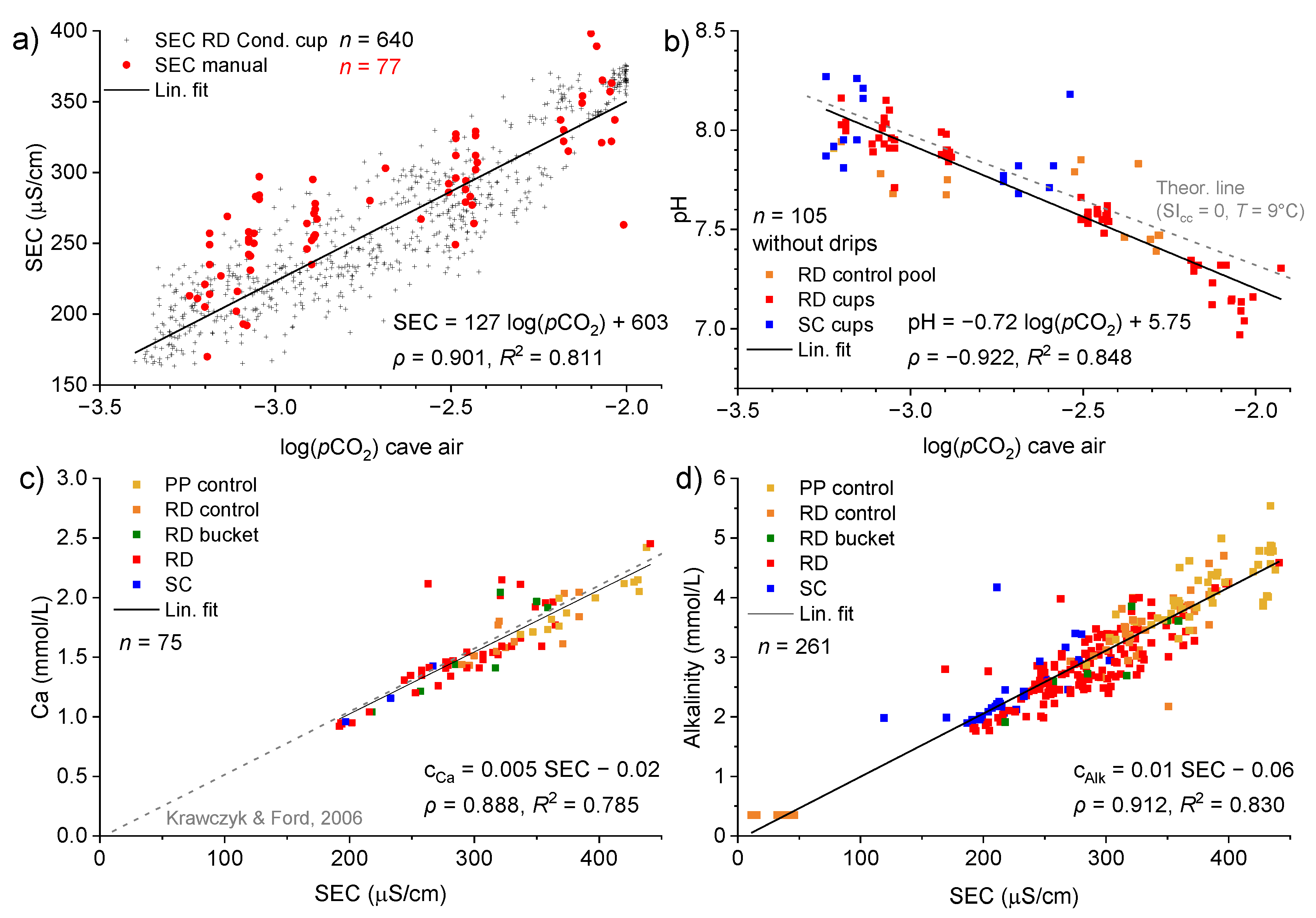
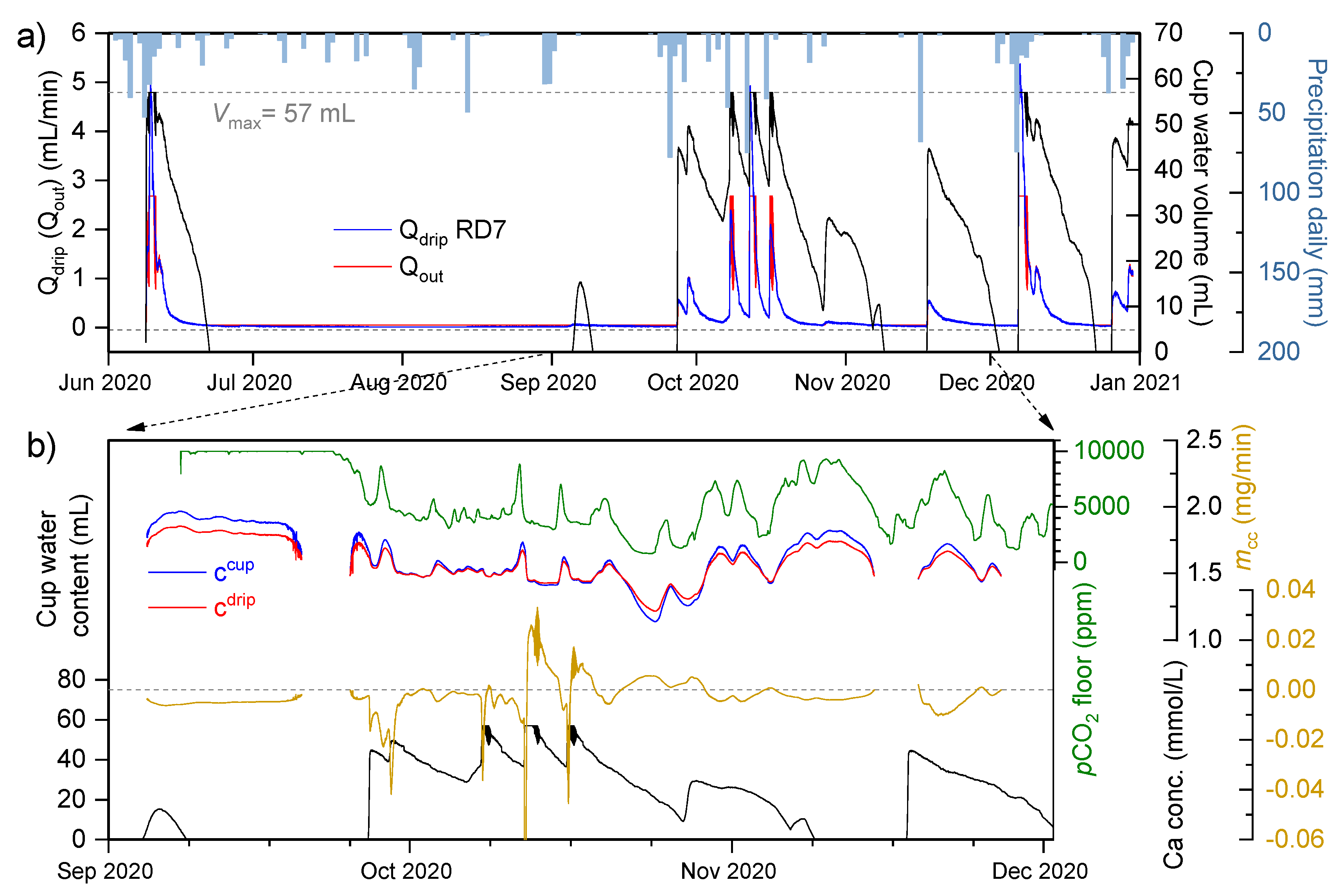
The time series of the Ca concentration in the cup, ccup, was obtained from a strong linear relationship with the SEC of the manually measured drips and cups (equation in Figure 10c).
(2)
The time series cdrip was calculated from a strong linear relationship between ccup and cdrip for the RD7 cup/drip samples (n = 5; ρ = 0.996, R2 = 0.989; cdrip = 0.77ccup + 0.34).
(3)
The drip discharge, Qdrip, was calculated from the continuous recording of the drip count, N, as described in Section 2.3 of the Materials and Methods.
(4)
The calculation of the drainage rate, Qout, required an on-site experiment. A selected cup near RD5 with a diameter of 3 cm and a depth of 8 cm was filled with water and connected to a graduated cylinder via a siphon. Both the cup and the cylinder were covered to restrain the water inflow. The natural drainage of water from the cup was followed by time-lapse photography of the graduated cylinder at 30-min intervals over a period of 40 h. The volume change in the cylinder and in the cup are equal to the amount of water drained from the cup, ΔVtot = QoutΔt. This gives the relationship between the drainage rate and the water level hw in the cup. We converted this value to the cup water volume V and normalised it based on the maximum water content in the cup, Vmax, so that Qout is a function of cup water content V V m a x . The data points were fitted to an exponential curve Q o u t = Q m i n + A e V V m a x τ (n = 39; R2 = 0.889), where the fitting parameters were Qmin (the minimum drainage rate; 0.05 mL/min), A, the amplitude (0.0012), and τ, the rate constant (−0.13). The Vmax of the cup was measured to be ~57 mL.
The calcite precipitation/dissolution mcc in the cup was then calculated step by step by interval t using the calculated time series:
(1)
First, the empty cup is filled with V = Qdript of water.
(2)
Qout is calculated based on the current and maximum water contents of the cup V and Vmax, respectively.
(3)
The corrected water volume in the cup is calculated as V Q o u t t .
(4)
The current cup water volume is now the sum of the previously corrected volume and the volume of the newly arrived drip water (Qdript).
(5)
With the values of ccup, cdrip and Qout for each successive step, mcc is calculated according to Equation (1).
Steps 2–5 are then repeated until the end of the available time series. Each time the cup is filled beyond the Vmax volume, the maximum Qout is reached (2.68 mL/min), and the water volume does not decrease again until Qdrip < Qout. Similarly, the minimum Qout (0.05 mL/min) exceeds the minimum Qdrip (0.014 mL/min, ~1 drop in 5 min), and therefore, the cup can run dry during the occasional dry periods. Figure 15a shows the results of the previous calculations, while Figure 15b compares the water dynamics in the cup with the pCO2 of the cave air, the Ca concentrations and the change in the mass of precipitated (positive) or dissolved (negative) calcite mcc. The dissolution dynamics, as shown by the time series of mcc, are consistent with the control mechanisms described in the previous section. The strongest dissolution is expected under high CO2 conditions, when the difference between the calcium concentration in the cup water and in the dripwater is the greatest and when the dripping is enhanced, resulting in the highest drainage rate.
From the total cumulative change in mcc over 1993 h (~83 days, ~12 weeks) between September and December 2020, we got a net change of −33 mg or 12 mm3 calcite. To convert this value into a precipitation or dissolution rate (in mm/y), we would need a growth model for a cup. Since we do not yet have such a model, we could make a rough estimate by dividing the volume of calcite removed by an average wetted surface area in a cup. From the volume-height relation and the radius of a cup (assuming a cylinder with a radius of 1.5 cm and a depth of 8 cm), we calculated the average wetted surface Sw = 8.5 cm2. Dividing the volume of removed calcite by the wetted surface area gave a dissolution rate of −0.014 mm. While this value was consistent with the estimate obtained from the limestone tablet [60], the time period of this estimate (September–December) was ~2.3 times shorter and excluded the summer period that was encompassed in the limestone tablet experiment, so the geochemical-based dissolution rate estimate could be a few times higher or even similar if the continuing winter period precipitation (e.g., January–March) were included. Nevertheless, if we go further and speculate on the age of the corrosion cups by assuming that the obtained dissolution rate corresponds to the annual estimate (i.e., −0.014 mm/y), that dissolution only occurs in a vertical direction and is constant in time, then an 8-cm-deep cup would form in ~6000 years.
Although the exact dissolution rates and the cup age estimates remain highly speculative and uncertain due to the combination of various correlations and assumptions, and the neglect of the kinetics of the reactions involving carbonate species or other variables, the calculations nevertheless provided values within a reasonable range. While our primary intent was to provide a qualitative measure, we have also proposed a method for estimating the dissolution rate that could certainly be further developed and refined. The model of the evolution of the corrosion cup shape could also be developed with more complex modelling and with additional measurements in the cave. However, whether this would be sufficient to provide certainty in extrapolating past processes is still up for debate. The main obstacle of dissolution remains that it does not archive palaeoclimate proxies as speleothems do, but we believe that its study nevertheless offers new insights into the workings of karst systems, processes and evolution.

5. Conclusions

In Pisani Passage of Postojna Cave, Slovenia, several hundred cup-shaped corrosion features and stalagmites affected by severe dissolution were found. Here, we investigated the most likely variables affecting the formation of corrosion cups: host rock composition, hydrology, spatial and temporal distribution of pCO2 in cave air and the geochemical evolution of the water from the vadose zone as cave dripwaters and within the corrosion cups. We found that the thickness of the rock overburden determined the initial calcium concentrations of the dripwaters, which decreased from the entrance of Pisani Passage (~100 m and ~2 mmol/L Ca) towards the Red Hall at the end of Pisani Passage (~30 m and ~1.5 mmol/L Ca), where most of the dissolution features were found. Seasonal cave ventilation controls the temporal dynamics of pCO2, with pCO2 minima in the winter and maxima in the summer. These seasonal pCO2 patterns imprint on the dripwater geochemistry, with positive calcite saturation indices in the winter and negative in the summer. The configuration of the airflow pathways favours the accumulation of CO2 at the floor level in the Red Hall, where the cups are located. This microclimatic setting allows the dripwaters, which are low in calcium, to shift towards undersaturation, leading to dissolution of the rock and speleothems on the cave floor. Conversely, at the control drip sites, precipitation is favoured by the overall higher Ca concentrations and lower average pCO2 of the cave air. We also found signs that the conditions promoting either precipitation or dissolution can change over time, illustrated by corrosion cups now covered by flowstone. The results of this study shed new light on fundamental karst processes and effects on the speleothem incubator, the understanding of which is crucial for palaeoclimate research.

Author Contributions

Conceptualisation, L.K., F.G. and V.E.J.; methodology, L.K., F.G. and V.E.J.; investigation, L.K., F.G. and V.E.J.; data curation, L.K.; writing—original draft preparation, L.K.; writing—review and editing, L.K., F.G. and V.E.J. and visualisation, L.K. All authors have read and agreed to the published version of the manuscript.

Funding

This research was partly funded by the project “Methodology for monitoring the sustainable use of karst show caves with automatic measurements—role model—Postojna cave” (L6-9397), which was financially supported by the Slovenian Research Agency. LK’s work was supported by the Young Researchers Programme of the Slovenian Research Agency. The automatic titrator and ion chromatograph of the laboratory of the Karst Research Institute ZRC SAZU were funded by the project “Development of research infrastructure for the international competitiveness of the slovenian rri space—RI-SI-LifeWatch”. The operation was co-financed by the Republic of Slovenia, Ministry of Education and Sport and the European Union from the European Regional Development Fund.

Data Availability Statement

The data presented in this study are available on request from authors.

Acknowledgments

We thank Boštjan Grašič and Primož Mlakar for setting up and maintaining the monitoring system in Postojna Cave. We thank Jan Rohovec from the Institute of Geology of the Czech Academy of Sciences for the sample preparation and elemental analyses of the rock samples. The manuscript benefited from helpful comments from four reviewers.

Conflicts of Interest

The authors declare no conflict of interest.

Abbreviations

Aamplitude constant in the calculation of the cup drainage rate
Alkcarbonate alkalinity
ccupCa concentration in cup water
cdripCa concentration in dripwater
hwwater level in the cup
log(pCO2)logarithm with base ten of CO2 partial pressure
m0 and Sfitting parameters in the calculation of drip discharge
mccdissolution or precipitation rate of calcite
Ndrip count
pCO2partial pressure of CO2 gas in air
pCO2(eq)partial pressure of CO2 gas in equilibrium with solution
pCO2(sat)partial pressure of CO2 gas in equilibrium with solution and saturated in respect to calcite
PCPprior calcite precipitation
PPPisani Passage
Qdripdrip discharge
Qminminimum cup drainage rate
Qoutcup water drainage rate
R2coefficient of determination
RDRed Hall
SECspecific electroconductivity (compensated at 25 °C)
SEMscanning electron microscope
SIcccalcite saturation index
Swwetted cup wall surface
Twater temperature
ttime period
Vwater volume in a cup
Vmaxmaximum cup water volume
WHWhite Hall
Δttime interval or interval between two consecutive drops
ΔVtottotal volume change in the cylinder-cup experiment
ρPearson’s correlation coefficient
ρwwater density
τrate constant in the calculation of cup drainage rate

References

  1. Fairchild, I.J.; Baker, A. Speleothem Science: From Process to Past Environments; A John Wiley & Sons, Ltd.: Hoboken, NJ, USA, 2012; ISBN 9781405196208. [Google Scholar]
  2. Lachniet, M.S. Climatic and Environmental Controls on Speleothem Oxygen-Isotope Values. Quat. Sci. Rev. 2009, 28, 412–432. [Google Scholar] [CrossRef]
  3. Spötl, C.; Fairchild, I.J.; Tooth, A.F. Cave Air Control on Dripwater Geochemistry, Obir Caves (Austria): Implications for Speleothem Deposition in Dynamically Ventilated Caves. Geochim. Cosmochim. Acta 2005, 69, 2451–2468. [Google Scholar] [CrossRef]
  4. Baldini, J.U.L.; Lechleitner, F.A.; Breitenbach, S.F.M.; van Hunen, J.; Baldini, L.M.; Wynn, P.M.; Jamieson, R.A.; Ridley, H.E.; Baker, A.J.; Walczak, I.W.; et al. Detecting and Quantifying Palaeoseasonality in Stalagmites Using Geochemical and Modelling Approaches. Quat. Sci. Rev. 2021, 254, 106784. [Google Scholar] [CrossRef]
  5. Sherwin, C.M.; Baldini, J.U.L. Cave Air and Hydrological Controls on Prior Calcite Precipitation and Stalagmite Growth Rates: Implications for Palaeoclimate Reconstructions Using Speleothems. Geochim. Cosmochim. Acta 2011, 75, 3915–3929. [Google Scholar] [CrossRef]
  6. Hartmann, A.; Baker, A. Modelling Karst Vadose Zone Hydrology and Its Relevance for Paleoclimate Reconstruction. Earth-Sci. Rev. 2017, 172, 178–192. [Google Scholar] [CrossRef]
  7. Surić, M.; Czuppon, G.; Lončarić, R.; Bočić, N.; Lončar, N.; Bajo, P.; Drysdale, R.N. Stable Isotope Hydrology of Cave Groundwater and Its Relevance for Speleothem-Based Paleoenvironmental Reconstruction in Croatia. Water 2020, 12, 2386. [Google Scholar] [CrossRef]
  8. Mattey, D.P.; Atkinson, T.C.; Barker, J.A.; Fisher, R.; Latin, J.P.; Durrell, R.; Ainsworth, M. Carbon Dioxide, Ground Air and Carbon Cycling in Gibraltar Karst. Geochim. Cosmochim. Acta 2016, 184, 88–113. [Google Scholar] [CrossRef]
  9. Baldini, J.U.L.; Baldini, L.M.; McDermott, F.; Clipson, N. Carbon Dioxide Sources, Sinks, and Spatial Variability in Shallow Temperate Zone Caves: Evidence from Ballynamintra Cave, Ireland. J. Cave Karst Stud. 2006, 68, 4–11. [Google Scholar]
  10. Breecker, D.O.; Payne, A.E.; Quade, J.; Banner, J.L.; Ball, C.E.; Meyer, K.W.; Cowan, B.D. The Sources and Sinks of CO2 in Caves under Mixed Woodland and Grassland Vegetation. Geochim. Cosmochim. Acta 2012, 96, 230–246. [Google Scholar] [CrossRef]
  11. Milanolo, S.; Gabrovšek, F. Analysis of Carbon Dioxide Variations in the Atmosphere of Srednja Bijambarska Cave, Bosnia and Herzegovina. Bound.-Layer Meteorol. 2009, 131, 479–493. [Google Scholar] [CrossRef]
  12. Banner, J.L.; Guilfoyle, A.; James, E.W.; Stern, L.A.; Musgrove, M. Seasonal Variations in Modern Speleothem Calcite Growth in Central Texas, U.S.A. J. Sediment. Res. 2007, 77, 615–622. [Google Scholar] [CrossRef] [Green Version]
  13. Baldini, J.U.L.; McDermott, F.; Hoffmann, D.L.; Richards, D.A.; Clipson, N. Very High-Frequency and Seasonal Cave Atmosphere PCO2 Variability: Implications for Stalagmite Growth and Oxygen Isotope-Based Paleoclimate Records. Earth Planet. Sci. Lett. 2008, 272, 118–129. [Google Scholar] [CrossRef]
  14. Baldini, J.U.L. Cave Atmosphere Controls on Stalagmite Growth Rate and Palaeoclimate Records. Geol. Soc. Spec. Publ. 2010, 336, 283–294. [Google Scholar] [CrossRef]
  15. Kukuljan, L.; Gabrovšek, F.; Covington, M.D.; Johnston, V.E. CO2 Dynamics and Heterogeneity in a Cave Atmosphere: Role of Ventilation Patterns and Airflow Pathways. Theor. Appl. Climatol. 2021, 146, 91–109. [Google Scholar] [CrossRef]
  16. Whitaker, T.; Jones, D.; Baldini, J.U.L.; Baker, A.J. A High-Resolution Spatial Survey of Cave Air Carbon Dioxide Concentrations in Scoska Cave (North Yorkshire, UK): Implications for Calcite Deposition and Re-Dissolution. Cave Karst Sci. 2009, 36, 85–92. [Google Scholar]
  17. Noronha, A.L.; Hardt, B.F.; Banner, J.L.; Jenson, J.W.; Partin, J.W.; James, E.W.; Lander, M.A.; Bautista, K.K. Trade Winds Drive Pronounced Seasonality in Carbonate Chemistry in a Tropical Western Pacific Island Cave—Implications for Speleothem Paleoclimatology. Geochem. Geophys. Geosystems 2017, 18, 384–399. [Google Scholar] [CrossRef]
  18. Frisia, S.; Fairchild, I.; Fohlmeister, J.; Miorandi, R.; Spötl, C.; Borsato, A. Carbon Mass-Balance Modelling and Carbon Isotope Exchange Processes in Dynamic Caves. Geochim. Cosmochim. Acta 2011, 75, 380–400. [Google Scholar] [CrossRef]
  19. James, E.W.; Banner, J.L.; Hardt, B. A Global Model for Cave Ventilation and Seasonal Bias in Speleothem Paleoclimate Records. Geochem. Geophys. Geosystems 2015, 16, 1044–1051. [Google Scholar] [CrossRef]
  20. Borsato, A.; Johnston, V.E.; Frisia, S.; Miorandi, R.; Corradini, F. Temperature and Altitudinal Influence on Karst Dripwater Chemistry: Implications for Regional-Scale Palaeoclimate Reconstructions from Speleothems. Geochim. Cosmochim. Acta 2016, 177, 275–297. [Google Scholar] [CrossRef]
  21. Railsback, L.B.; Liang, F.; Vidal Romaní, J.R.; Grandal-d’Anglade, A.; Vaqueiro Rodríguez, M.; Santos Fidalgo, L.; Fernández Mosquera, D.; Cheng, H.; Edwards, R.L. Petrographic and Isotopic Evidence for Holocene Long-Term Climate Change and Shorter-Term Environmental Shifts from a Stalagmite from the Serra Do Courel of Northwestern Spain, and Implications for Climatic History across Europe and the Mediterranean. Palaeogeogr. Palaeoclimatol. Palaeoecol. 2011, 305, 172–184. [Google Scholar] [CrossRef]
  22. Baldini, J.U.L.; McDermott, F.; Fairchild, I.J. Spatial Variability in Cave Drip Water Hydrochemistry: Implications for Stalagmite Paleoclimate Records. Chem. Geol. 2006, 235, 390–404. [Google Scholar] [CrossRef]
  23. White, J.H.; Domínguez-Villar, D.; Hartland, A. Condensation Corrosion Alters the Oxygen and Carbon Isotope Ratios of Speleothem and Limestone Surfaces. Results Geochem. 2021, 2, 100008. [Google Scholar] [CrossRef]
  24. White, W.B. Chemistry and Karst. Acta Carsologica 2015, 44, 349–362. [Google Scholar] [CrossRef]
  25. Johnston, V.; Martín-Pérez, A.; Skok, S.; Mulec, J. Microbially-Mediated Carbonate Dissolution and Precipitation; towards a Protocol for Ex-Situ, Cave-Analogue Cultivation Experiments. Int. J. Speleol. 2021, 50, 137–155. [Google Scholar] [CrossRef]
  26. Spötl, C.; Pavuza, R.; Dublyansky, Y. Hypogene Caves in Austria. Hypogene Speleogenes 2009, 69, 121–127. [Google Scholar]
  27. Treble, P.C.; Fairchild, I.J.; Griffiths, A.; Baker, A.; Meredith, K.T.; Wood, A.; McGuire, E. Impacts of Cave Air Ventilation and In-Cave Prior Calcite Precipitation on Golgotha Cave Dripwater Chemistry, Southwest Australia. Quat. Sci. Rev. 2015, 127, 61–72. [Google Scholar] [CrossRef]
  28. Faimon, J.; Ličbinská, M.B.; Zajíček, P.; Sracek, O. e Partial Pressures of CO2 in Epikarstic Zone Deduced from Hydrogeochemistry of Permanent Drips, the Moravian Karst, Czech Republic. Acta Carsologica 2012, 41, 47–57. [Google Scholar] [CrossRef] [Green Version]
  29. Milanolo, S.; Gabrovšek, F. Estimation of Carbon Dioxide Flux Degassing from Percolating Waters in a Karst Cave: Case Study from Bijambare Cave, Bosnia and Herzegovina. Chem. Der Erde 2015, 75, 465–474. [Google Scholar] [CrossRef]
  30. Hansen, M.; Dreybrodt, W.; Scholz, D. Chemical Evolution of Dissolved Inorganic Carbon Species Flowing in Thin Water Films and Its Implications for (Rapid) Degassing of CO2 during Speleothem Growth. Geochim. Cosmochim. Acta 2013, 107, 242–251. [Google Scholar] [CrossRef]
  31. Appelo, T.; Postma, D. Geochemistry, Groundwater and Pollution, 2nd ed.; CRC Press: Balkema, Rotterdam, 2005. [Google Scholar]
  32. Prelovšek, M.; Šebela, S.; Turk, J. Carbon Dioxide in Postojna Cave (Slovenia): Spatial Distribution, Seasonal Dynamics and Evaluation of Plausible Sources and Sinks. Environ. Earth Sci. 2018, 77, 289. [Google Scholar] [CrossRef]
  33. Gregorič, A.; Vaupotič, J.; Gabrovšek, F. Reasons for Large Fluctuation of Radon and CO2 Levels in a Dead-End Passage of a Karst Cave (Postojna Cave, Slovenia). Nat. Hazards Earth Syst. Sci. 2013, 13, 287–297. [Google Scholar] [CrossRef]
  34. Šebela, S. Postojna—Planina Cave System, Slovenia. In Encyclopedia of Caves; White, W.B., Culver, D.C., Pipan, T.B.T.-E., Third, E., Eds.; Academic Press: Cambridge, MA, USA, 2019; pp. 812–821. ISBN 978-0-12-814124-3. [Google Scholar]
  35. Šebela, S. Accesses from the Surface to the Postojna Cave System. Ann. Ser. Hist. Nat. 2010, 20, 55–64. [Google Scholar]
  36. Šebela, S.; Vaupotič, J.; Košťák, B.; Stemberk, J. Direct Measurement of Present-Day Tectonic Movement and Associated Radon Flux in Postojna Cave, Slovenia. J. Cave Karst Stud. 2010, 72, 21–34. [Google Scholar] [CrossRef]
  37. ARSO Ministry of the Environment and Spatial Planning, Slovenian Environmental Agency. Available online: http://meteo.arso.gov.si/met/en/ (accessed on 6 May 2021).
  38. Šebela, S. Geological Characteristics of Pisani Rov in Postojna Cave [in Slovene]. Acta Carsologica 1992, 21, 97–116. [Google Scholar]
  39. Šebela, S. Broken Speleothems as Indicators of Tectonic Movements. Acta Carsologica 2008, 37, 51–62. [Google Scholar] [CrossRef] [Green Version]
  40. Krajnc, B.; Ferlan, M.; Ogrinc, N. Soil CO2 Sources above a Subterranean Cave—Pisani Rov (Postojna Cave, Slovenia). J. Soils Sediments 2017, 17, 1883–1892. [Google Scholar] [CrossRef]
  41. Kogovšek, J. Water Percolation and Sinter Deposition in Pisani Rov of Postojnska Jama [in Slovene]. Acta Carsologica 1983, 11, 59–76. [Google Scholar]
  42. Mattey, D.P.; Collister, C. Acoustic Drip Counters for Environmental Monitoring. BCRA Cave Radio Electron. Gr. 2008, 70, 14–17. [Google Scholar]
  43. Collister, C.; Mattey, D. Controls on Water Drop Volume at Speleothem Drip Sites: An Experimental Study. J. Hydrol. 2008, 358, 259–267. [Google Scholar] [CrossRef]
  44. Kogovšek, J. Distribution of Some Elements during Sinter Forming in the Karst Caves [in Slovene]. Acta Carsologica 1981, 9, 114–126. [Google Scholar]
  45. Baker, A.; Barnes, W.L.; Smart, P.L. Variations in the Discharge and Organic Matter Content of Stalagmite Drip Waters in Lower Cave, Bristol. Hydrol. Process. 1997, 11, 1541–1555. [Google Scholar] [CrossRef]
  46. Kogovšek, J.; Petrič, M. Solute Transport Processes in a Karst Vadose Zone Characterized by Long-Term Tracer Tests (the Cave System of Postojnska Jama, Slovenia). J. Hydrol. 2014, 519, 1205–1213. [Google Scholar] [CrossRef]
  47. Kukuljan, L.; Gabrovsek, F.; Covington, M. The Relative Importance of Wind-Driven and Chimney Effect Cave Ventilation: Observations in Postojna Cave (Slovenia). Int. J. Speleol. 2021, 50, 275–288. [Google Scholar] [CrossRef]
  48. Krawczyk, W.E.; Ford, D.C. Correlating Specific Conductivity with Total Hardness in Limestone and Dolomite Karst Waters. Earth Surf. Process. Landf. 2006, 31, 221–234. [Google Scholar] [CrossRef]
  49. Vokal, B.; Obeli, B.; Genty, D.; Kobal, I.; Obeliê, B. Chemistry Measurements of Dripping Water in Postojna Cave. Acta Carsologica 1999, 28/1, 305–321. [Google Scholar]
  50. Šebela, S.; Čar, J. Velika Jeršanova Doline—A Former Collapse Doline. Acta Carsologica 2000, 29, 201–212. [Google Scholar] [CrossRef]
  51. Gams, I. Factors and Dynamics of Corrosion of the Carbonatic Rocks in the Dinaric and Alpine Karst of Slovenia (Yugoslavia) [in Slovene]. Geogr. Vestn. 1966, 38, 11–68. [Google Scholar]
  52. Baker, A.; Flemons, I.; Andersen, M.S.; Coleborn, K.; Treble, P.C. What Determines the Calcium Concentration of Speleothem-Forming Drip Waters? Glob. Planet. Chang. 2016, 143, 152–161. [Google Scholar] [CrossRef]
  53. Noronha, A.L.; Johnson, K.R.; Southon, J.R.; Hu, C.; Ruan, J.; McCabe-Glynn, S. Radiocarbon Evidence for Decomposition of Aged Organic Matter in the Vadose Zone as the Main Source of Speleothem Carbon. Quat. Sci. Rev. 2015, 127, 37–47. [Google Scholar] [CrossRef] [Green Version]
  54. Bergel, S.J.; Carlson, P.E.; Larson, T.E.; Wood, C.T.; Johnson, K.R.; Banner, J.L.; Breecker, D.O. Constraining the Subsoil Carbon Source to Cave-Air CO2 and Speleothem Calcite in Central Texas. Geochim. Cosmochim. Acta 2017, 217, 112–127. [Google Scholar] [CrossRef]
  55. Blecha, M.; Faimon, J. Karst Soils: Dependence of CO2 Concentrations on Pore Dimension. Acta Carsologica 2014, 43, 55–64. [Google Scholar]
  56. Treble, P.C.; Fairchild, I.J.; Baker, A.; Meredith, K.T.; Andersen, M.S.; Salmon, S.U.; Bradley, C.; Wynn, P.M.; Hankin, S.I.; Wood, A.; et al. Roles of Forest Bioproductivity, Transpiration and Fire in a Nine-Year Record of Cave Dripwater Chemistry from Southwest Australia. Geochim. Cosmochim. Acta 2016, 184, 132–150. [Google Scholar] [CrossRef] [Green Version]
  57. Pracný, P.; Faimon, J.; Sracek, O.; Kabelka, L.; Hebelka, J. Anomalous Drip in the Punkva Caves (Moravian Karst): Relevant Implications for Paleoclimatic Proxies. Hydrol. Process. 2016, 30, 1506–1520. [Google Scholar] [CrossRef]
  58. Pracný, P.; Faimon, J.; Kabelka, L.; Hebelka, J. Variations of Carbon Dioxide in the Air and Dripwaters of Punkva Caves (Moravian Karst, Czech Republic). Carbonates Evaporites 2016, 31, 375–386. [Google Scholar] [CrossRef]
  59. Smith, A.C.; Wynn, P.M.; Barker, P.A.; Leng, M.J. Drip Water Electrical Conductivity as an Indicator of Cave Ventilation at the Event Scale. Sci. Total Environ. 2015, 532, 517–527. [Google Scholar] [CrossRef] [Green Version]
  60. Johnston, V.E.; Košir, A.; Martín-Pérez, A. Evaluating Carbonate Dissolution and Precipitation in a Short Time-Frame Using SEM: Techniques and Preliminary Results from Postojna Cave, Slovenia. Acta Carsologica 2021. accepted for publication. [Google Scholar]
Figure 1. A simplified conceptual model of chemical water evolution in the karst system, showing the dominant processes of CO2 absorption or degassing and calcite dissolution or precipitation. The solid lines show the processes taking place in the vadose zone, while the dashed lines represent the processes in a cave. Pathways that result in calcite precipitation are shown in blue, while those that cause dissolution are red. The regions with expected Ca concentrations and log(pCO2) values for the soil or cave water are shown by grey ellipses. However, the exact position of a particular solution within the pathway is arbitrary but roughly corresponds to the conditions found in this study. The grey lines with constant saturation indices were calculated in the speciation software PHREEQC for T = 9 °C [31]. The precipitation pathways (solid blue lines) start from a high CO2 environment at point A (pCO2 = 10−1.7, ~20,000 ppm). Dissolution of the host rock can follow either a closed system A to B or an open system A to C to reach calcite saturation. Dripwater B or C enters the cave and degasses, causing supersaturation with respect to calcite and calcite precipitates towards D (blue dashed lines), which is in equilibrium with the current pCO2 of the cave air. The dissolution pathways (solid red lines) show water entering the cave either undersaturated with respect to calcite due to incomplete dissolution of the host rock (E to F), allowing calcite dissolution in the cave (F to G), or saturated with calcite that then absorbs CO2 from the cave air (D to H or G to H), permitting the dissolution of cave carbonates.
Water 13 03184 g001
Figure 2. Location of the study site. (a) Map of Slovenia showing the location of the cave and plan of Postojna Cave. The typical ventilation pattern is indicated by red and blue arrows showing summer and winter ventilation, respectively. (b) Plan of Pisani Passage showing the locations of the numerous corrosion features and sampling sites. (c) Plan of the Red Hall showing the largest number of corrosion cups in Pisani Passage. The extent of the corrosion features is indicated by dashed red lines, which are explained in the text. The sampled drip sites are marked with inverted triangles (drips), circles (cups), diamonds (pools) and triangles (bucket). RD drips are coloured red, RD cups and SC drips with dark blue, RD control drip with orange, RD bucket with green, PP control drips with yellow, and three drips located near the entrance of PP with violet. Continuous pCO2 monitoring sites are indicated by green circles. Map source: Cave cadastre of the Karst Research Institute ZRC SAZU.
Water 13 03184 g002
Figure 3. Photos of a selection of corrosion features. (a) Boulders in the Red Hall, covered by a thin flowstone crust and corrosion cups. (b) Wide shallow RD1 cup with heavily corroded surroundings due to splashing. (c) An example of a stalagmite that is heavily corroded by several drips. (d) RD2 cup covered in flowstone and containing broken crystals. A yellow tape measure with a length of 10 cm or a 14-cm-long pen was used as a scale.
Water 13 03184 g003
Figure 4. Rock sample with corrosion cups taken from SC Hall in Pisani Passage. Elemental composition samples were taken from seven different locations on the surface and marked with an asterisk, here six shown in (a) (E1–E6) and one in (b) (E7; the back of the rock sample).
Water 13 03184 g004
Figure 5. Classification of the drip spots based on manual measurements of the maximum drip discharges and their coefficients of variation following Baker et al. [45].
Water 13 03184 g005
Figure 6. (a) Time series of the drip discharge and water balance on a monthly basis summarised for the period 2017–2020. The blue and red columns show the positive and negative water balances (excess or deficit, respectively), calculated as the difference between precipitation and net evapotranspiration (calculated with the Penman-Monteith equation) [37]. The black boxes show the climatic averages (1981–2010). (b) A 6-month window of the drip response to precipitation events (blue bars on a daily scale). The seepage flow with a fracture-fed component is represented by RD1 (red curve), while the seepage flow with a typical diffuse component is represented by RD5 and RD7 (orange and yellow curves). Both diffuse drips did not respond to summer precipitation, while RD1 showed a very low response. The precipitation data are from the Postojna National Meteorological Station, located 2.5 km SSW of Pisani Passage [37]. (c) Inset from (b) showing a higher resolution in a shorter time frame with continuous electroconductivity (SEC) from the RD Cond. and RD7 cups (dashed and solid blue curves) and pCO2 on the cave floor (green line). The lag time between the pCO2 peaks and the responses to the SEC peaks ranges from a few hours to about 12 h (marked by black arrows).
Water 13 03184 g006
Figure 7. Time series of the daily pCO2 fluctuations in the Red Hall at the floor (dark green) and ceiling (light green) compared to the SEC (red line) measured in the RD Cond. cup. The green shading represents the differences in the CO2 concentrations between the floor and the ceiling of the Red Hall.
Water 13 03184 g007
Figure 8. Linear correlation between the Ca concentrations and carbonate alkalinity for the samples where the Ca concentrations were measured manually, titrimetrically or via IC at IZRK. The linear relationship was used to calculate the Ca concentrations in incorrectly analysed samples. The similar slope of the theoretical line (pure Ca(HCO3)2 solution; dashed line) and the fitted line (solid line) confirms that the water samples are indeed mostly of the Ca-HCO3 type, regardless of the sampling site or the time period of sampling. However, a positive deviation of the Ca concentration can be seen in the samples analysed with the titrimetric method and a negative deviation in the samples analysed with the IC, the causes of which are unknown.
Water 13 03184 g008
Figure 9. Collated monthly averages of the cave air and water data collected during 2017–2020. Time series of the alkalinity (a), Ca concentration (b), SEC (c), pH (d), SIcc (e) and cave air pCO2 (f) for different sampling sites in Pisani Passage. The black dashed line in (c) shows the values of the continuous records from the SEC of the RD Cond. cup. Monthly pCO2 values in Red Hall were calculated from a continuous time series for the floor and ceiling (Figure 7), while PP represents the mean pCO2 values measured manually at the PP control sites. The horizontal black dashed line represents the atmospheric value (400 ppm).
Water 13 03184 g009
Figure 10. Correlation between the log(pCO2) at the floor and the manual or continuous SEC values (a) or pH measurements of the cup or pool water (b). Correlation between the SEC and manual calcium concentrations (c) or alkalinity (d). The grey dashed line in (c) represents the linear regression for clean limestone waters with a low total hardness (<600 µS/cm) based on a large dataset [48].
Water 13 03184 g010
Figure 11. Water chemistry evolution for the drip and cup water samples collected at Pisani Passage. The grey curves denote constant SIcc values at T = 9 °C. The arrows show the direction of the dominant processes in the carbonate water chemistry. Explanations can be found in the text. The green line marks the log(pCO2) range measured in the soil, while the blue and red dashed lines mark the winter and red ranges, respectively.
Water 13 03184 g011
Figure 12. (a) Schematic profile of Pisani Passage (PP) showing the sites sampled during a single occasion on 14 July 2021. The profile of the surface was acquired from LiDAR scans and followed the extent of the passage [37]. The colours of sampling sites are analogous to the one used in Figure 2b,c. (b) Relationship between the calcium concentrations in the dripwaters and the distance from the entrance of Pisani Passage or (c) the thickness of the rock overburden determined by the LiDAR digital elevation model. Note the inverted X-axis in (c). Linear regressions were only calculated for the drip samples (black triangles) but excluding samples BL3, SC1 and the SC stream, as these were considered outliers.
Water 13 03184 g012
Figure 13. Variation in the pCO2(sat) values (pCO2(eq) of the solution forced to SIcc = 0; solid lines) for different drips in Pisani Passage compared to the pCO2 dynamics of the cave air in the Red Hall summarised on a monthly scale (dashed lines). The red shading indicates the range of potential dissolution in the Red Hall (i.e., water pCO2(sat) < pCO2 of the cave air), while the blue shading indicates precipitation.
Water 13 03184 g013
Figure 14. Dripwater SIcc in Pisani Passage as a function of log(pCO2). The grey lines denote the processes of CO2 absorption or degassing from a parent solution (assuming SIcc = 0, T = 9 °C) and range from log(pCO2) = −3.2 (~630 ppm) to log(pCO2) = −1.6 (~25,000 ppm). The measured ranges of the cave air pCO2 are marked by dashed lines for the winter (blue) and summer (red) for the ceiling and floor CO2 probes. Note that, at a cave air pCO2 of 10−2.2 (6300 ppm), the RD drips associated with the corrosion cups fall exclusively in the undersaturated area. The lowest value of SIcc is reached by the RD bucket.
Water 13 03184 g014
Figure 15. (a) Results of the calculation of the dynamics of the cup water volume (black curve) from the dripwater discharge Qdrip (blue curve) and the drainage rate Qout (red curve) compared to the daily precipitation (blue bars). The maximum volume Vmax was calculated to be 57 mL, while the minimum volume could drop to zero (dry cup). (b) Comparison between pCO2 at the floor level, the Ca concentration in the cup and the drip, the change in calcite mass (precipitation—positive; dissolution—negative) and the cup water content. The largest negative spikes in mcc occur when the pCO2 is high, just before the cup is full and when Qout is highest.
Water 13 03184 g015
Table 1. Elemental composition of the surface features of a rock sample containing corrosion cups. The units are the mass percentage per sample. The labels E1–E7 correspond to the ones shown in Figure 4.
SampleCaMgNaKSrSFeAlSiP
Rock #1 (E3)97.930.890.420.250.0360.260.070.060.070
Rock #2 (E5)97.720.820.560.200.0310.330.120.130.090
Rock #3 (E6)97.640.910.560.450.0450.220.040.050.090
Rock #4 (E7)97.840.820.430.340.0350.240.040.090.160
Flowstone—yellow #1 (E2)99.230.080.250.190.0030.090.040.040.040.027
Flowstone—yellow #2 (E4)98.940.080.370.250.0020.170.070.060.050.011
Flowstone—red (E1)97.850.090.710.580.0020.310.130.160.160.005
Publisher’s Note: MDPI stays neutral with regard to jurisdictional claims in published maps and institutional affiliations.

