Review

An Overview of the Numerical Approaches to Water Hammer Modelling: The Ongoing Quest for Practical and Accurate Numerical Approaches

by
Susovan Pal
1,
Prashanth Reddy Hanmaiahgari
1,* and
Bryan W. Karney
2,*
1
Department of Civil Engineering, Indian Institute of Technology Kharagpur, Kharagpur 721302, India
2
Department of Civil and Mineral Engineering, University of Toronto, Toronto, ON M5S 1A4, Canada
*
Authors to whom correspondence should be addressed.
Water 2021, 13(11), 1597; https://doi.org/10.3390/w13111597
Submission received: 14 May 2021 / Accepted: 1 June 2021 / Published: 5 June 2021
(This article belongs to the Section Hydraulics and Hydrodynamics)

Abstract

:
Here, recent developments in the key numerical approaches to water hammer modelling are summarized and critiqued. This paper summarizes one-dimensional modelling using the finite difference method (FDM), the method of characteristics (MOC), and especially the more recent finite volume method (FVM). The discussion is briefly extended to two-dimensional modelling, as well as to computational fluid dynamics (CFD) approaches. Finite volume methods are of particular note, since they approximate the governing partial differential equations (PDEs) in a volume integral form, thus intrinsically conserving mass and momentum fluxes. Accuracy in transient modelling is particularly important in certain (typically more nuanced) applications, including fault (leakage and blockage) detection. The FVM, first advanced using Godunov’s scheme, is preferred in cases where wave celerity evolves over time (e.g., due to the release of air) or due to spatial changes (e.g., due to changes in wall thickness). Both numerical and experimental studies demonstrate that the first-order Godunov’s scheme compares favourably with the MOC in terms of accuracy and computational speed; with further advances in the FVM schemes, it progressively achieves faster and more accurate codes. The current range of numerical methods is discussed and illustrated, including highlighting both their limitations and their advantages.

1. Introduction

Increases in computational power create an opportunity for analysts to better understand many complex phenomena, including water hammer. In essence, water hammer events involve hydraulic shock waves generated in a pipeline by rapid changes in one or more boundary values, such as valve closure. Such actions can have a devastating effect on system operation if improperly managed. As per Toro [1], shock waves of strong character are a very rapid transition of a physical quantity (i.e., pressure, density, or temperature). Water hammer problems with a rapid boundary change characterized, for example, by a valve closure time that is less than the wave return time over the entire system length, produce such rapid changes of pressure and velocity that the motion is typically characterized as a mathematical discontinuity. However, even with significant increases in computational speed, complex and multidimensional fluid problems still require a daunting numerical budget, whether using computational fluid dynamics (CFD) or considering the detailed transient modelling of a complex pipe network. This paper reviews advances in the numerical modelling of transient pressurized flow, highlighting the use of the more recently developed finite volume method (FVM) for water hammer work.
What makes the finite volume (FV) approach special is that it evaluates the conservative forms of the governing partial differential equations (PDEs) in algebraic form [1,2]. Indeed, the FVM is developed by considering a small volume surrounding each nodal point in a geometric mesh, and then relating the volume integral to the surface integrals using the divergence theorem. The resulting surface integrals act as fluxes at the boundaries of each finite volume, and the whole formulations enable the tracking of the evolution of a system’s state.
In addition to a general overview of the traditional method of characteristics (MOC) and finite difference method (FDM) computational approaches, this paper highlights some newer developments in the numerical approach to water hammer analysis. In particular, the paper summarizes the inherent limitations of traditional methods—limitations that naturally lead to the introduction of the various FV approaches. The paper concludes by suggesting several directions for future research.

2. Governing Equations

Numerical estimates of water hammer pressure and flow are obtained by approximating the solutions of the governing continuity and momentum equations. To that end, several numerical methods are available.

2.1. Full-Form 1D Equations

The 1D governing equations for water hammer can be derived from considerations of conservation of mass and momentum, and are often written as follows [2,3]:
t ( P V ) + ( V ρ a 2 1 ρ V ) x ( P V ) = ( 0 g sin θ f | V | V D )
where P is the pressure,   V is the velocity,   ρ is the fluid density,   g is the gravitational acceleration, θ is the pipe slope,   D is the pipe diameter, a is the celerity, f is the Darcy–Weisbach friction factor, x is the spatial coordinate along the pipeline, and t is the time.
The one-dimensional flow equations can also be written as:
U t + F ( U ) x = S
where U is the vector of flow variables, F is the flux vector, and S is the source term vector. By comparison, in the one-dimensional Euler equation used in gas dynamics, the terms U   and   F are represented as:
U = ( ρ ρ V E )   and   F ( U ) = ( ρ ρ V 2 + P V ( E + P ) )
where total energy E is ρ ( 1 2 V 2 + e ) , the first term specifies the kinetic energy, and the second term specifies the internal energy of the gas. Note that the governing equation for water hammer varies from that of gas dynamics (Euler equation), primarily in terms of the energy conservation equation. In water hammer, the energy conservation equation is dropped based on the (usually reasonable) assumption of a negligible change in water temperature over a transient event. Equation (2) can be further simplified as:
U t + J U x = S
where J is the vector of time dependent flow variables in the x direction.
Riemann Invariant: The Riemann invariant is a key conceptualization in various formulations, and is essentially a mathematical transformation of the governing conservation forms. Riemann invariants assist in the solution of the governing equations along the characteristic curves.
Considering only the hyperbolic portion of Equation ( 4 ) —that is, assuming the source term S = 0 —the governing equation can be expressed as K 1 U t + K 1 JKK 1 U x = 0 , and given that dW = K 1 dU produces:
W t + Λ W x = 0
where Λ is a diagonal that contains the eigenvalues of matrix J , hence for the pth term:
W ( p ) t + λ ( p ) W ( p ) x = 0
where λ ( p ) is the pth eigenvalue.
Hence, the total derivative is given as D W ( p ) D t = 0 along d x d t = λ ( p ) .
Thus, this equation effectively defines the invariance of function W(p) along the characteristic line x = λ ( p ) t + x 0 , where W(p) is the pth Riemann invariant. Now, for the more general case involving m − 1 waves, the Riemann invariants can be expressed as:
d U 1 K 1 ( p ) = d U m K m ( p ) = constant   across   d x d t = λ ( p )
where K 1 ( p ) is the pth eigenvector of Λ . Equation (7) is known as a generalized Riemann invariant. A schematic of the generalized Riemann problem is graphically conceptualized in Figure 1.

2.2. Simplified Equations

An early fundamental form for an analytical solution of the simplified water hammer equations was presented by Joukowsky [4] as follows:
Δ P = ± ρ a Δ V   or   Δ H = ± a Δ V g
where a is the celerity or acoustic wave speed, P is the pressure head = ρ g ( H z ) , Z is the elevation of the pipe centreline from a given datum, H is the piezometric head, ρ is the fluid density, V is the cross-sectional average velocity, u is the local longitudinal velocity, A is the cross-sectional area of the pipe, and g is the gravitational acceleration. The ± sign typically represents whether the water hammer wave is moving upstream or downstream. Allievi [5] developed the theory in the form of a differential equation relating the pressure gradient to the total derivative ( P x = ρ g d V d t ) .
The underlying assumptions in Equations (1), (2), and (4) include slightly deformable pipes and slightly compressible fluid. If we were to suppose that the fluid is incompressible and that the pipe walls are rigid, the transient flow then becomes a so-called rigid column motion—a motion in which the fluid velocity and pressure changes propagate instantaneously throughout the pipe system. The rigid column theory is generally applicable to relatively slow transients when the action of the boundary conditions gives rise to inertial effects but is too slow to evoke notable compressibility effects.
Solving Equations (1) and (4) numerically presents several challenges. Streeter and Lai [6] numerically formulated the governing Equations (1) and (4), initially accounting for their intrinsic nonlinearity. However, they also demonstrated that the nonlinear convective terms V V x and V P x are relatively small and, thus, justified their neglect. Moreover, the body force due to gravity is also often considered negligible. The simplified conservation PDEs, given by Chaudhry [3], Fox [7], and Wylie and Streeter [8] are often written as follows:
a 2 g V x + H t = 0
V t + g H x + 4 ρ D τ w = 0
where H is the piezometric pressure head = P / γ , and τ w is the shear stress at the pipe wall.

2.3. Finite Volume Method

The equations presented so far are considered the classical 1D water hammer equations, and full derivations are found in the works of Chaudhry [3] and Wylie and Streeter [8]. Interestingly, alternate approaches usually utilize different presentations of the equations. Thus, for the FVM approach, the following form similar to Equation (2) is usually preferred [9,10] for its intrinsic conservation of mass and momentum:
U t + F x = S
in which U = [ μ M ] , F = [ M A ˇ P + M 2 / μ ] ,   and   S = [ 0 ρ A ˇ f | V | V 2 D ] , where A ˇ is the average cross-sectional area of the pipe, M is the mass flowrate, μ is the mass of fluid per unit length of pipe, and M is the fluid’s momentum ( M = μ V = ρ A ˇ V ) . The wave celerity can be defined as a = d ( A ˇ   P ) d μ . Variables μ and M are conservative; they can be converted to non-conservative pressure and density forms as required by using the following equation, which is obtained by integrating the wave celerity equation:
P = P f + a 2 A ( μ μ ref )
where μ ref = A ˇ ρ ref , ρ ref is the reference fluid density, and a is the wave velocity.
Equation (11) is classified as a hyperbolic system of conservation laws, and expresses its characteristic form assuming that U and F are continuous in space and time, and F is only a function of U [10]:
U t + J U x = S
In this case, the Jacobian matrix of a flux vector is:
J = [ M μ M M μ ( M μ + A ˇ p ) M ( M μ + A ˇ p ) ] = [ 0 1 a 2 V 2 2 V ]
where J is the Jacobian matrix of F in Equation (11). The solution methodology associated with Equation (11) is summarized here in the section on the finite volume approach.

2.4. Two-Dimensional Flows
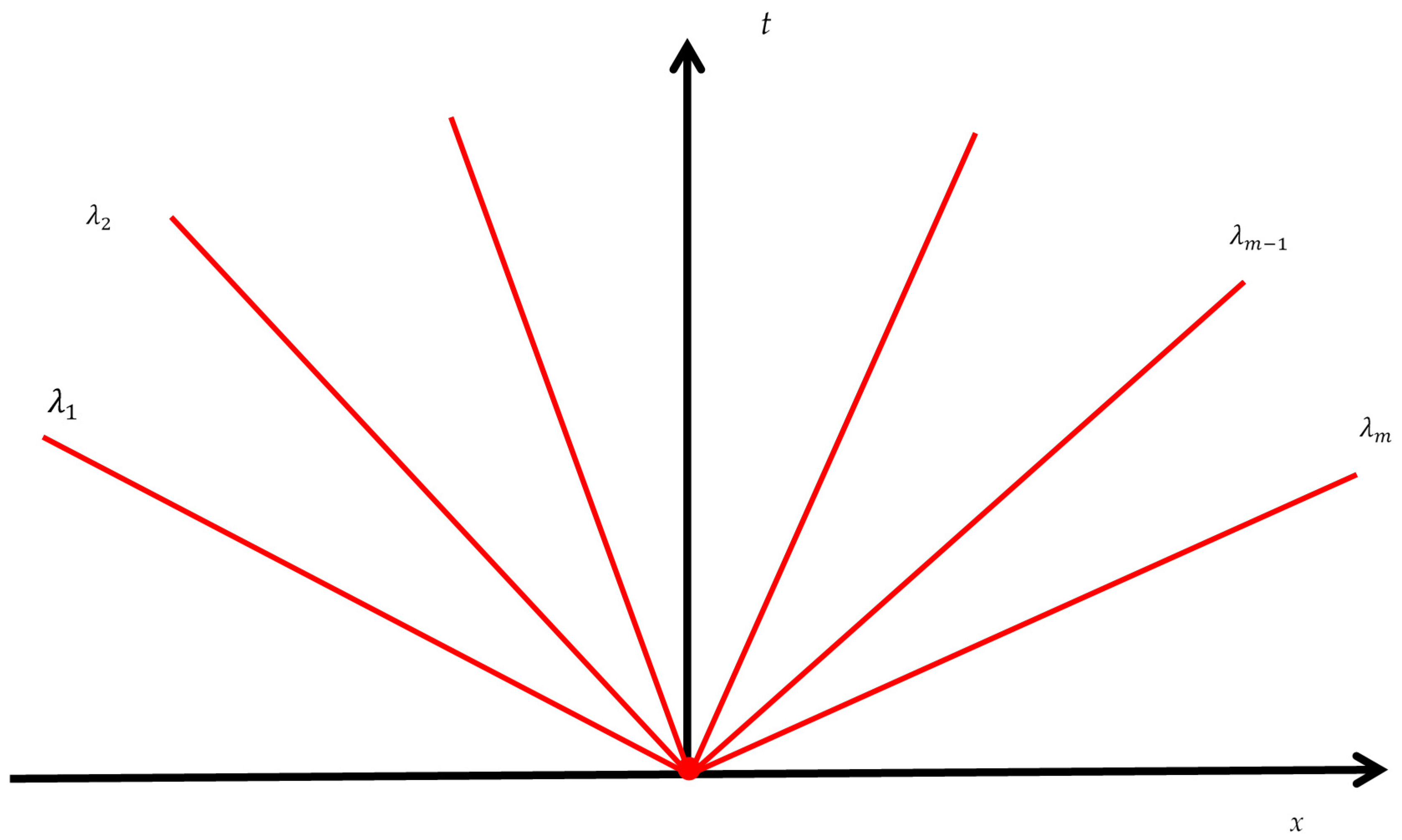
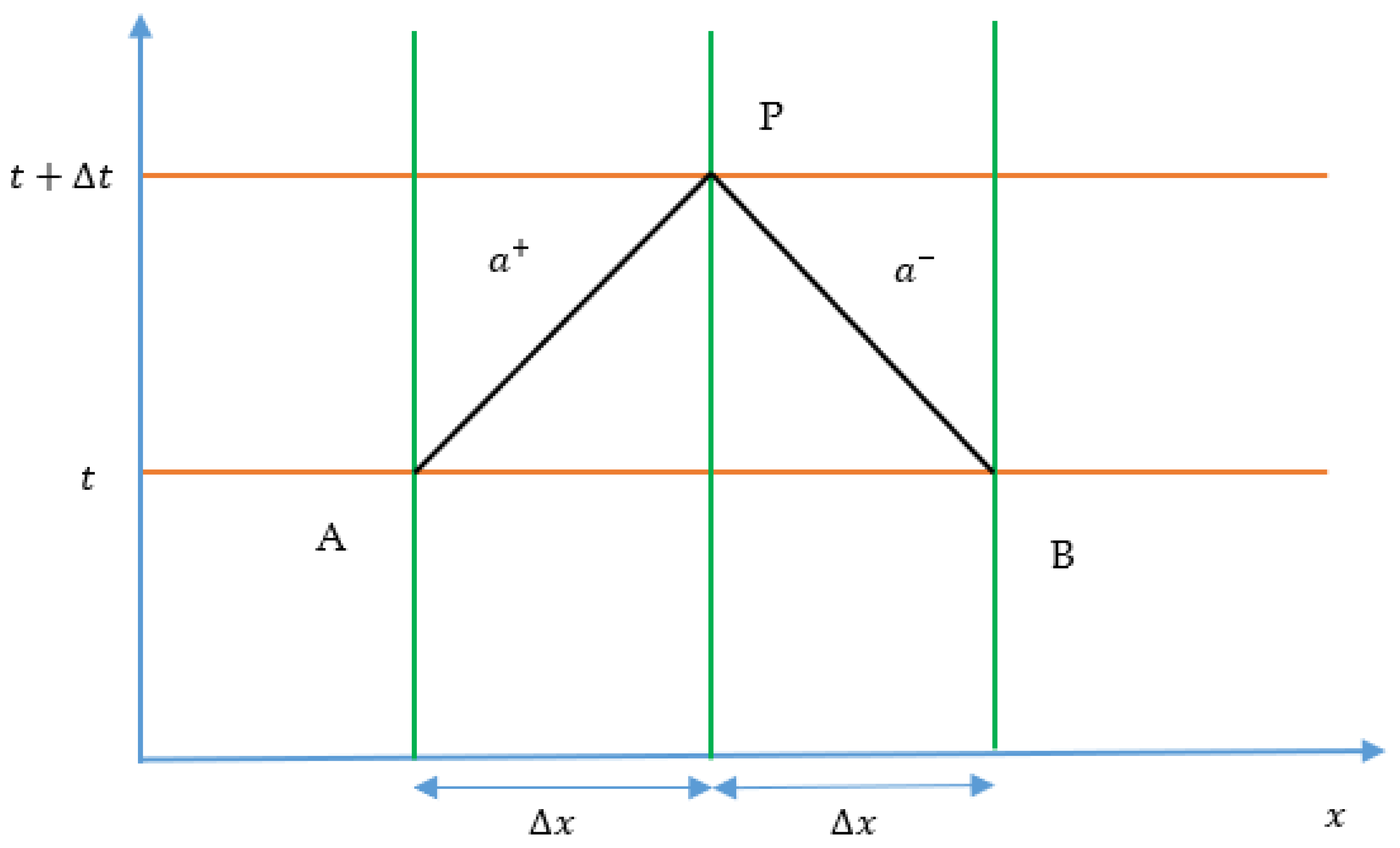
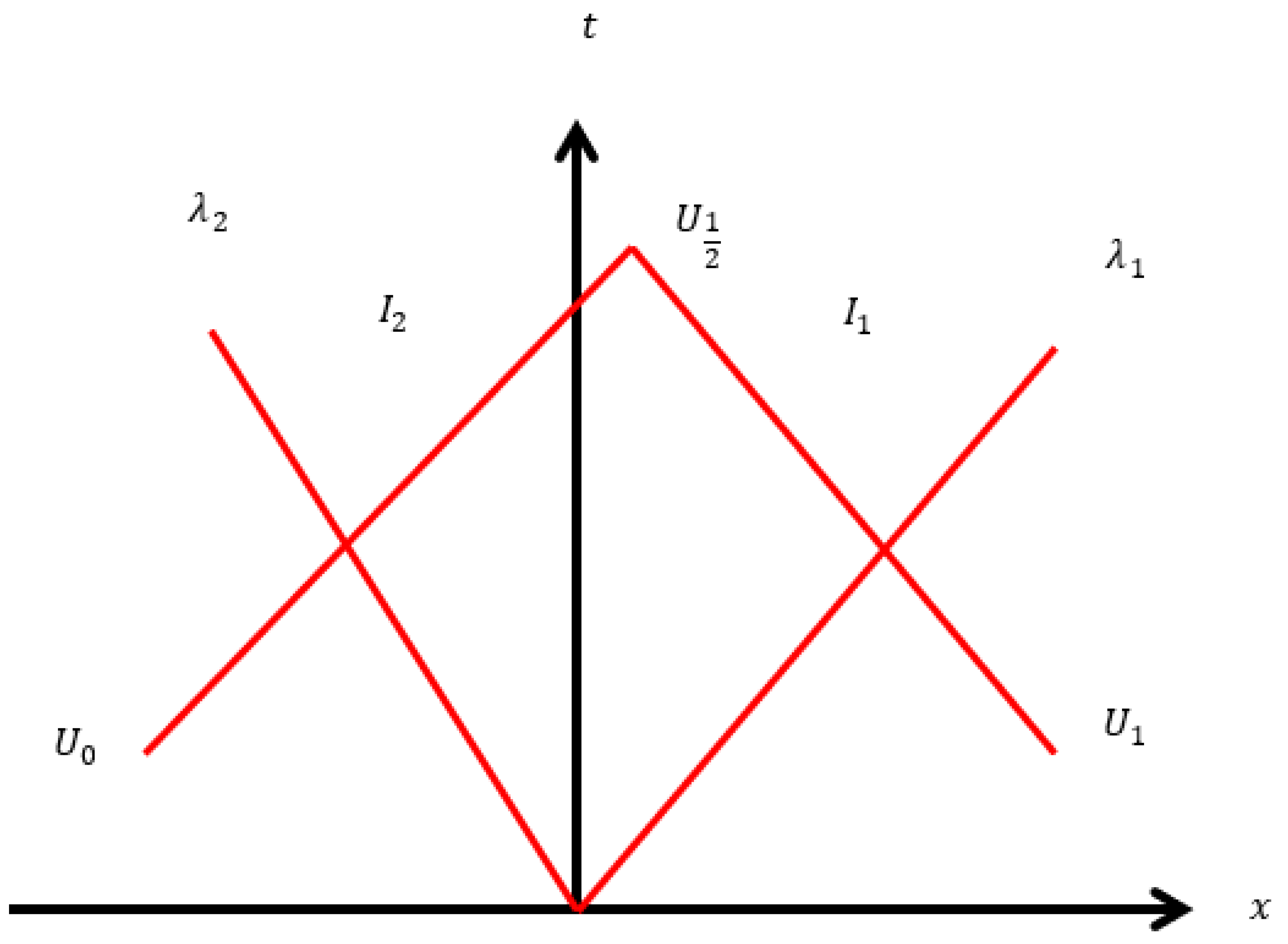
If a more accurate estimate of shear stress is required, a 2D version of the flow can be used. The general governing equation of two-dimensional models after dropping the source term can take the following forms:
U t + F x + G y = 0
U t + J F U x + J G U y = 0
The constants J F and J G are the Jacobian matrices of F and G with respect to U [11]. The most common semi-two-dimensional, non-conservative administering conditions were given by Vardy and Hwang [12]. Although these conditions were produced using different methodologies, and are clearly structured differently, they can be described by the following pair of continuity and momentum equations in radial coordinates:
g a 2 ( H t + V H x ) + V x + 1 r r ν x = 0
V t + V V x + ν V r = g H x 1 r ρ r τ r
where r is the radial distance,   ν is the kinematic viscosity of the fluid, t is the time, and x is the distance along the pipe, H ( x , t ) is the piezometric head, V ( x , r , t ) is the radial velocity, and τ is the shear stress.
Owing to the turbulent nature of pipe flow, Reynolds averaging is performed in order to obtain the time-averaged solutions of Navier–Stokes equations. The time-averaging produces a new term known as Reynolds shear stress ρ u v ¯ , where u and v are velocity fluctuations in the x and r directions, respectively. Using the well-known Boussinesq approximation, the Reynolds shear stress can be expressed as ρ u v ¯ = μ T V r , where μ T is the eddy viscosity. Therefore, the total shear stress consists of two components—namely, viscous shear stress, and Reynolds shear stress. The total shear stress as a function of the velocity gradient is written as τ = ρ ν V r ρ u v ¯ = (   μ D + μ T ) V r , where μ D represents dynamic viscosity.
Neglecting nonlinear terms, Equations (17) and (18) can be rewritten as:
g a 2 H t + V x + 1 r r ν r = 0
V t + g H x + 1 r ρ r τ r = 0
Furthermore, Equation (20) can be simplified using d A = 2 π r d r , which results in the following:
V t + g H x + 2 π ρ ( r τ ) A = 0
Equations (19) and (21) are RANS (Reynolds-averaged Navier–Stokes) equations. Solution of RANS equations requires turbulence closure models. There are various turbulence closure models: zero-equation (mixing-length model), one-equation, two-equation, and seven-equation models. Zero-equation models are widely used: for example, the Cebeci–Smith model, Baldwin–Lomax model, Johnson–King model, and a roughness-dependent model [13]. One-equation models usually solve an equation for the turbulent kinetic energy, which is obtained during the averaging process. One-equation models include Prandtl’s one-equation model, the Baldwin–Barth model, and the Spalart–Allmaras model. Although the Spalart–Allmaras model is a simple one-equation model based on the kinematic turbulent viscosity, it is not popular for water hammer analysis. More advanced models such as k ε and k ω models solve two equations—one for kinetic energy, and the other for the rate of dissipation of turbulent kinetic energy. An extended list of the turbulence models is given in Section 6.1.
Equations (19) and (21) are typically solved using one of a variety of available Reynolds-averaged Navier–Stokes (RANS)-equation-based turbulence models, such as two-layer or three-layer eddy viscosity models (e.g., [14] and [15]). Detailed implementation strategies for the eddy viscosity turbulence closure model for a system experiencing sudden valve closure are summarized in the works of Hanmaiahgari and Maji [16] and Silva-Araya and Chaudhry [17].

3. MOC Schemes

Although MOC schemes are well known by both researchers and practitioners, to facilitate comparison, it is valuable to quickly summarize the key MOC approaches here. In essence, the MOC approach converts the governing pair of PDEs into a set of four coupled ODEs [3,8]. This transformation preserves many of the attributes of the original equations, and lends itself to fast, accurate, and intuitive codes. However, one fundamental challenge is that the MOC specifies a fixed relationship between space and time steps (see Figure 2)—a requirement that can create numerical challenges in complex systems with many pipe segments, or in systems with a variable wave speed.
Resolving the integration of properties along the characteristic lines can be done either explicitly or implicitly. In the explicit method of characteristics, unknown values at time t + Δ t are obtained point-by-point by integrating characteristic lines from time t to time t + Δ t , in which the source term is computed using the known values at time t . In the implicit method of characteristics, unknown values at time t + Δ t are obtained simultaneously by integrating characteristic lines; however, for computational simplicity, the source (friction) term is computed by blending the known values at time t and the unknown values at time t + Δ t .
Gray [19] first used the MOC to compute pressure and velocity in a frictionless pipe system using fixed Δ t and Δ x intervals. Lister [20] investigated the fixed-grid method and the method of specified time intervals, and concluded that the fixed-grid method facilitates programming, leading directly to its popularity. Lai [21] included the frictional losses in the MOC. Streeter [22] developed the boundary conditions in the MOC for opening and closing the valves. Streeter and Lai [6] experimentally validated the MOC for different valve closure times. Perkins [23] proposed that the fixed-grid method is numerically stable only for Courant numbers less than unity. However, in order to efficiently resolve device behaviour with the fixed-grid scheme, a common time step for all pipes is essential, creating a challenge to satisfy the Courant condition C r = a Δ t Δ x 1 . To address this problem, space-line interpolations were suggested to approximate the head and flow at the foot of the characteristic line [20]. This approach allowed the use of different time steps for specific pipes, thus permitting faster codes with still manageable errors. Vardy [24] proposed reachout– space-line interpolation for applying the MOC to pipe networks. This method also requires interpolation at the boundary, causing generation of error and propagation of the error over time. To overcome the limitations of space-line interpolation, Wiggert and Sandquist [25] combined space-line interpolation and space reachout interpolation. In contrast, Goldberg and Wylie [26] developed a relatively more accurate time-line interpolation method, which uses the results from previous time step data to carry out the interpolation. A combination of all of the available interpolation techniques was presented by Lai [27] under the name of the multimode scheme. This method provides a vast range of choices for Δ t   and   Δ x , thus offering considerable flexibility. Sibetheros et al. [28] demonstrated that a spline strategy is often well suited to adapting MOC grids to more complex domains, and specifically to anticipating transient conditions at unknown points when the general transient behaviour is known. Figure 3 depicts various interpolation techniques.
It is worth mentioning that interpolation is fundamentally non-physical, and inevitably introduces numerical errors in the form of dissipation and dispersion. Here, the term nonphysical is used, since it produces false or artificial diffusion, resulting from the numerical approximation of the convection term in the conservation equations [29]. Though dissipation and dispersion errors are normally presented, the first-order phase error is usually less apparent due to the numerical dissipation of the method. Moreover, the phase error is small; thus, a travelling wave proceeds (on average) at the correct speed a .
Moreover, interpolated methods have no intrinsic difficulty in accounting for the convection term in the momentum equations. In such an approach, the characteristic speeds change to u   ±   a . Thus, there is a slight asymmetry in the left and right running characteristics. For a user of MOC, there are two choices: using interpolation and accepting the numerical error but avoiding limitations to the physics and geometry; or, alternatively, to set the C r = 1 case, where the convection term must be dropped, and accepting some limitation or distortion on the system’s geometry. The latter is a minor issue today, since the computing power permits the use of very short spatial increments Δ x .
Ghidaoui and Karney [30] analyzed a wave speed adjustment method; therefore, characteristic lines pass through the known-time-level grid points to unknown-time-level grid points. Karney and Ghidaoui [31] introduced a hybrid interpolation technique in which they considered a combination of numerous approaches for interpolation. The composite calculation [31] can be executed as a preprocessor step, and consequently utilizes memory effectively, executes rapidly, and provides an adaptable tool for discretization in pipe networks. Ghidaoui et al. [32] proposed an integrated-energy approach in order to comprehend and control the discretization errors associated with space-line and time-line interpolation methods. Shimada et al. [33,34,35] introduced an exact method to compute the numerical errors of both space-line and time-line interpolation methods. According to Ghidaoui et al., [36], interpolation distorts the physics, and it is particularly problematic in short pipes due to the requirement of involving several reaches, implying the need for tiny time steps and greater computational times.
Tian et al. [37] worked to moderate valve-induced water hammer effects on a parallel pipe system using the MOC method. Adopting an alternate startup process, they found that using a damping torque could effectively reduce the induced pressure vibration due to valve closure. Bergant et al. [38,39] highlighted several additional transient processes, including fluid–structure interaction (FSI), and showed how they could be included in the MOC scheme. They investigated various parameters affecting water hammer, and suggested terms for unsteady friction, cavitation, and viscoelasticity, as well as how to represent both leakages and blockages. The first of their papers deals with mathematical models to incorporate those effects, while the second presents case studies along with comparisons of the MOC to the rigid-pipe approach.
Afshar and Rohani [18] proposed an implicit MOC model to address the shortcomings of the widely used MOC model. They simulated two transient flow problems, and favourably compared the predicted results with an explicit MOC scheme.
Column separation generally occurs when the calculated pressure becomes less than the saturated vapor pressure—a remarkably common complication during certain transient flows. One of the most well-known and utilized methods for modelling cavitation is to use a discrete vapor cavity model (DVCM), as developed by Wylie and Streeter [8]. Bergant and Simpson [40] modified the standard DVCM model by incorporating shock waves and other interactions. This new model is known as the generalized interface vaporous cavitation model (GIVCM), and provides a simpler and more numerically stable approach to column separation. Bergant and Simpson [41] provided a detailed comparison between the experimental and numerical results. Sadafi et al. [42], using the GIVCM, investigated column separation caused by the rapid closure of a valve—an outcome that led to pipe failure.
When rapidly filling an empty pipe, the resulting momentum of the water column when arrested can lead to severe pressures—an outcome widely investigated. For example, Wang and Yang [43] combined an MOC approach with an implicit solution to the filling problem, and showed that a coupled explicit–implicit method can provide accurate and stable numerical results.
Jang et al. [44] developed a new model with a quasi-2D approach based on the MOC, in order to reduce the computational nodes by proposing 1D characteristic equations for pressure and discharge. They showed that this method can give equivalent results to those obtained with an explicit 2D solution.

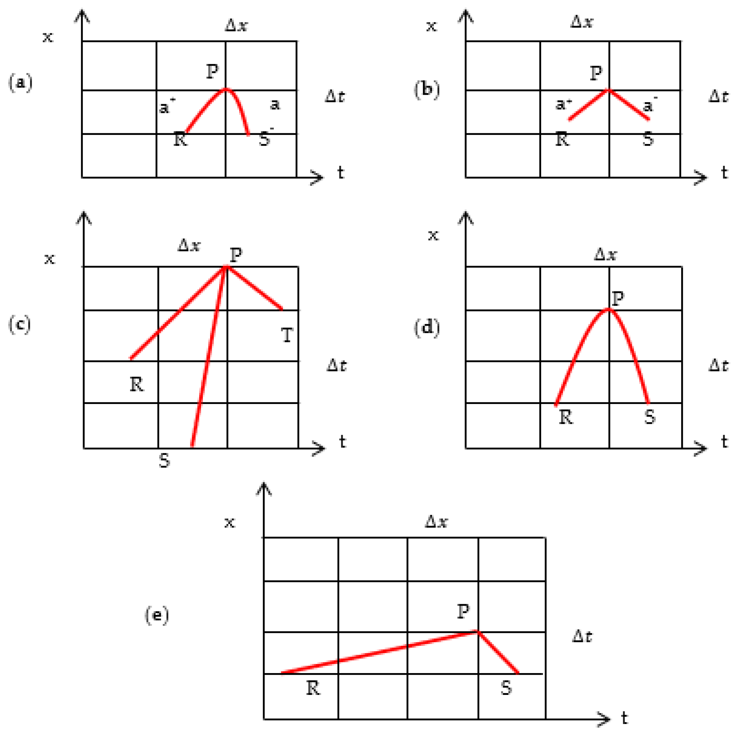
3.1. Limitations of MOC

Historically, the most popular approaches for solving water hammer problems have been the MOC-based methods. The MOC initially gained popularity due to its explicit nature, accuracy, computational speed, and comparative simplicity. Such methods directly track the movement of hydraulic disturbances. In fact, the MOC preserves wave behaviour, which is useful for modelling high-frequency transient events. In the MOC, the convective terms are typically neglected, because the Riemann invariants in the water hammer problem are only weakly interdependent [9]. As long as the wave speed is constant and a V , dropping the convective term makes sense, and the MOC is well suited to describe transient events. In any case, the finite volume method tends to be as sensitive to the wave damping as the MOC if a first-order method is used. However, the MOC approaches have some notable disadvantages:
  • The MOC approaches must be artificially modified if the Courant number is not set to unity [25,30]. Furthermore, mass and momentum conservation are not assured for non-uniform Courant numbers [45]. Interpolation is nonphysical, and tends to cause artificial damping of the solution [25,46].
  • The MOC makes it difficult to include the convective acceleration term—a reality that can occasionally induce errors, particularly when the objective is to find a solution with C r = 1 [47].
  • Conservation of momentum and mass cannot be ensured even if interpolation is not required.
  • Overall, the MOC approach is best suited to systems with invariant celerity, since a condition of C r = 1 can be met.
  • For C r = 1, explicit schemes are easy to program, and provide simpler solutions, whereas implicit schemes are more complex and computationally demanding to both code and execute [43]. The application of the explicit scheme is conditionally stable because of the source term, as discussed in Section 4.1, whereas the implicit scheme is unconditionally stable. Despite the popularity of explicit and implicit schemes, such approaches are often computationally inaccurate when used with larger spatial steps or conduits with variable cross-sectional areas [43].
Besides these concerns, complex device characteristics (e.g., for pumps and turbines), and even unsteady friction—not to mention certain air–water interactions—can be thought of as hints that simplified models themselves have limitations that can confound 1D analysis.

3.2. Need for Improved Numerical Methods

Thus, considerable challenges in water hammer calculations remain when using traditional MOC solvers. For example, when drawing water from a lake or reservoir, transient events can cause air to be released or to be entrained in the flow, causing the wave celerity to vary both temporally and spatially. Air release and reabsorption may require the modelling of heat transfer between air and water, which affects the dissipation of air pressure oscillations. In such cases, better numerical approaches may be both necessary and justified. Specific cases include multidimensional domains, cases where the wave speed is variable (e.g, associated with the gas release or readsorption with strong pressure changes), or occasionally in cases involving higher velocities within highly flexible pipes. Such applications tend to induce significant errors in traditional schemes, and thus justify a search for improved schemes.
In particular, the so-called inverse methods change the usual approach of predicting the response given by the system to one where the response is measured, and consistent system attributes are sought. According to Duan et al. [15], inverse methods use the entire transient response in the time domain for calibration, thereby utilizing both the leak-induced damping and reflection information. For that reason, inverse methods have become understandably more popular for finding anomalies in water networks and for calibrating systems. Inverse methods are typically more sensitive than typical design calculations to parameter values. Indeed, inverse problems are not well posed mathematically and, thus, demand more than an estimate of the maximum and minimum pressures—values that are often central to design questions. In fact, inverse methods perform well only when there is an accurate match between computed and measured time series. Unsteady pipe flows are sometimes characterized by temporal changes of wave speed and unsteady friction, influencing experimental outcomes and timings. In this context, the computational effort is still important, but achieving high accuracy, though of great value, has tended to be elusive to achieve in practice.

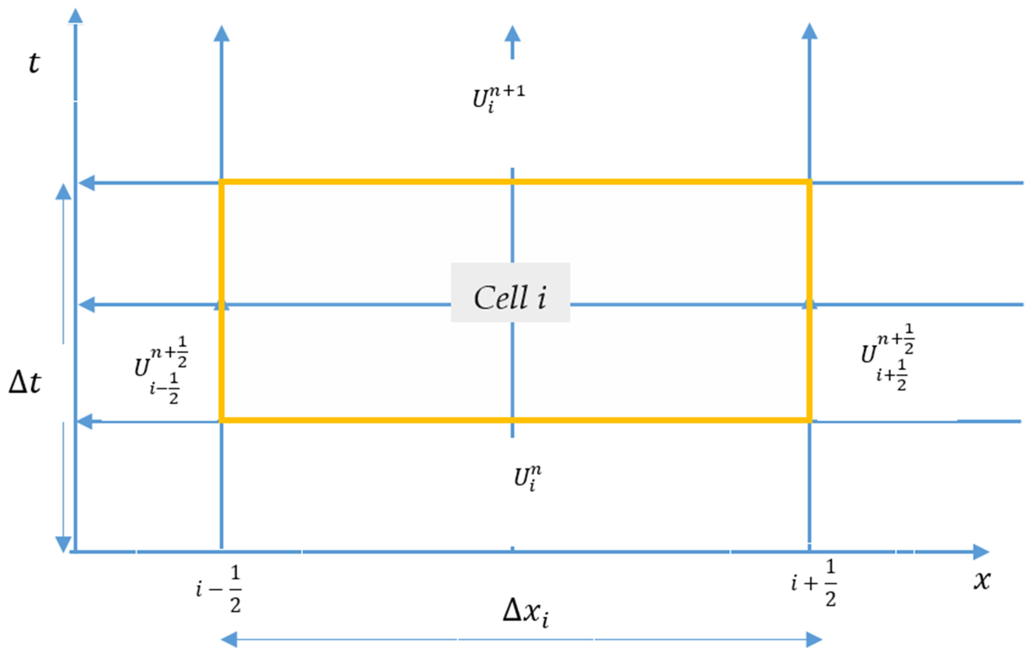
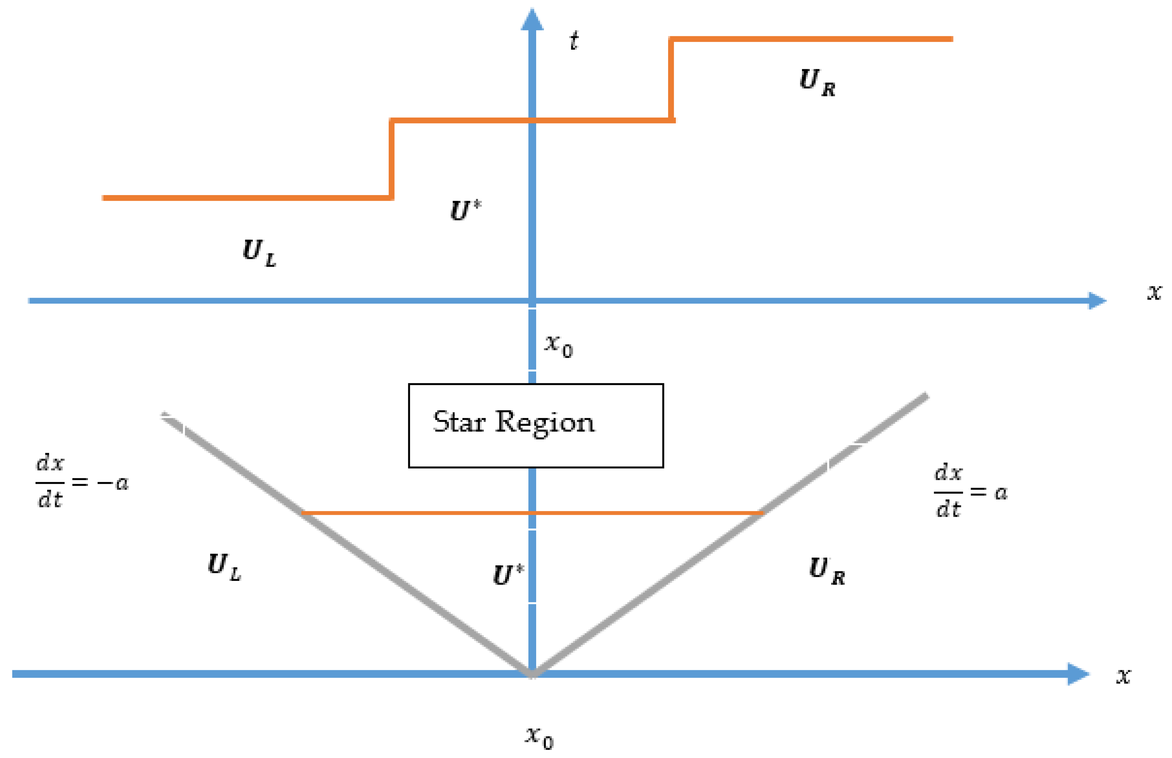
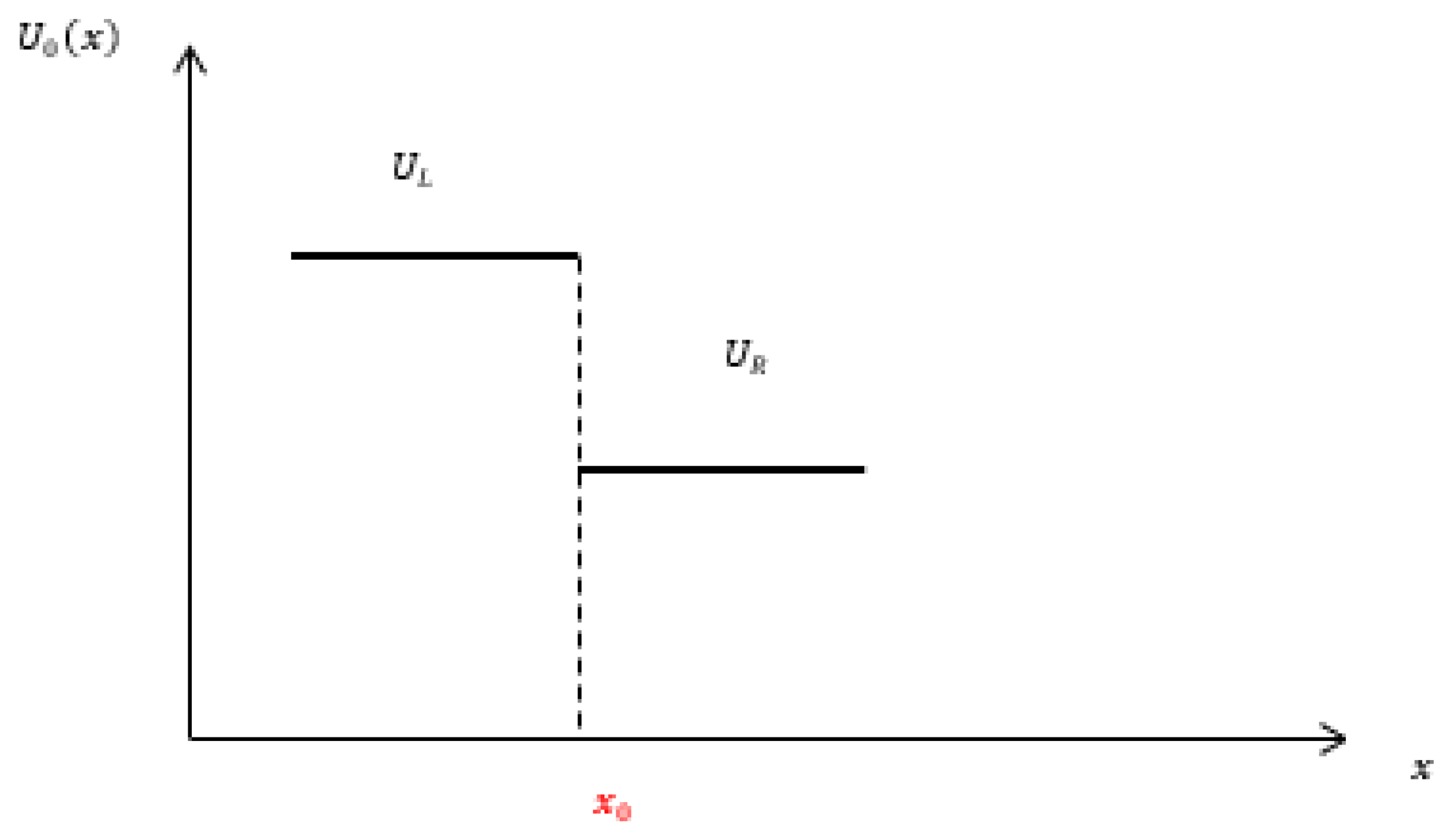
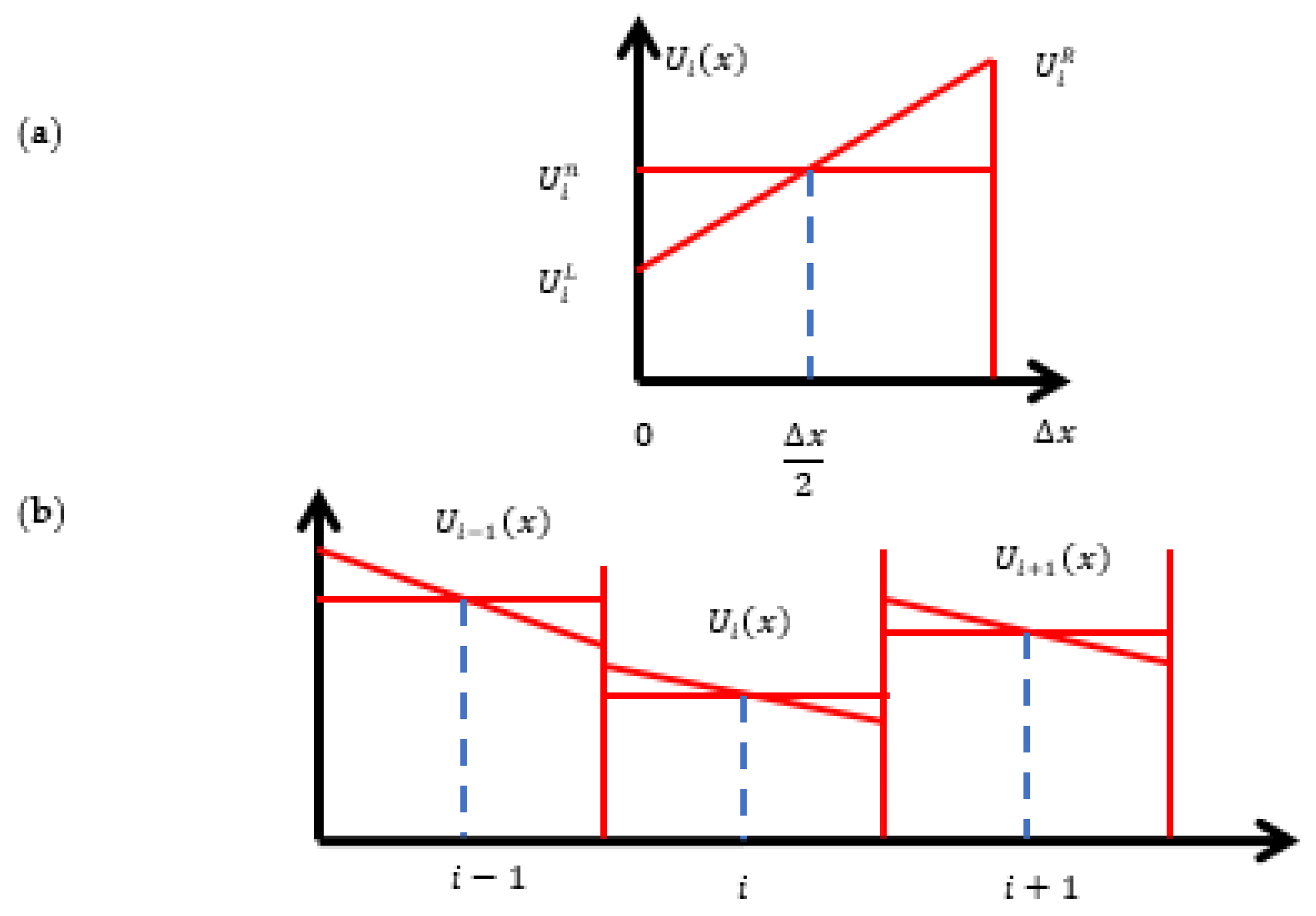
4. The Finite Volume Method (FVM)

The FVM is an example of a Godunov-type [48] algorithm, and is a technique for solving hyperbolic equations. Guinot [9,11,49] recommended this method because of its desirable attribute of conserving mass, momentum, and energy within a control volume for solving partial differential equations. This can solve either exact or approximate Riemann problems at each intercell boundary, primarily with the attribute of first-order accuracy in both space and time. The usually small control volume used in this context is often referred to as a cell (Figure 4). Unlike finite difference methods, the FVM does not usually retain state values at grid points, but rather stores average values within a cell. Finite volume methods update these average values by accounting for the mass and momentum flux contributions at the cell boundaries within a single time step [50]. However, both the MOC and FVM are based on the Riemann invariant.
In the MOC, non-conservative governing equations are integrated along the characteristic lines, whereas in the FVM, integration is done for an individual cell. In fact, there are many approaches based on the method chosen for time integration of the derivative with respect to space in the FVM [10]. Generally, integration in the FVM scheme is carried out in two steps: In the first step, non-conservative governing equations are integrated along characteristic lines, assuming a piecewise linear variation of the dependent variables, to find numerical fluxes at control volume (cell) boundaries. In the second step, conservative governing equations are integrated over time space within the control volume, and the computed values are represented at the cell centroid. Either only the interpolation is made on the boundaries, and a time integration is done separately using—for example—the Crank–Nicolson method, or a three-level implicit method; or else the second-order accuracy in time is obtained by adding the first step to compute values at time level t + Δ t 2 . There is an analogy between this method and the classic Lax–Wendroff method, or a two-step Lax–Wendroff method. Naturally, this approach is explicit, and is well suited for wave propagation problems. The first (implicit) approach is used by commercial CFD codes, as well as by thermal–hydraulic codes.

4.1. Finite Volume Method (FVM) Numerical Procedure

The finite volume method is broadly utilized in hyperbolic problems, including gas dynamics, shallow water flows, and many other contexts [1]. However, using this method for solving water hammer problems is fairly recent. This method has a clear advantage of better capturing shocks and discontinuities [51]. Mass conservation with the FVM approach is exact, but occurs in the MOC only when the solution is sufficiently accurate. However, in the case of two-phase flow, conservation never occurs with the MOC approach. For example, MOC methods usually deal with variable celerity problems by either interpolating parameters that are inaccurate and may cause mass conservation problems, or by forcing the celerity to be a constant using some procedure, such as that used in the discrete gas cavity model (DGCM). Such resolutions can cause serious numerical errors [52]. Although initially neglected, Guinot [9] applied the finite volume method to water hammer modelling by assuming a compressible pipe with its walls deforming elastically under pressure changes; that the conduit remains full; that friction losses and velocity head are negligible; that velocity is uniform over the cross-section; and that the reservoir level remains constant. He disregarded the advective terms, and built up a Riemann-type scheme, thus creating a first-order accurate FV scheme—an approach that was quite similar to the MOC with direct space-line interpolation. Guinot [9] expressed the governing equations for the water hammer in conservative form. Guinot’s [9] approach has recently been implemented by Pal et al. [53].
The crucial takeaway from this is that this paper contains important concepts of the methodology and, thus, assists comprehension. In this method, Equation (13) is solved in two steps: The first step solves the homogeneous part of Equation (13), i.e., U t + J U x = 0 . The next step solves the non-hyperbolic source term U t = S . Thus, the nonlinear hyperbolic problem is converted to an initial boundary value problem, and the partial differential equation will be of the form:
U t + F x = 0
having specified initial and boundary conditions as per problem requirements. Considering the integral form of the equation in domain [ x 1 , x 2 ] × [ t 1 , t 2 ] , in each cell I i = [ x i 1 2 , x i + 1 2 ] :
x 1 x 2 U ( x , t 2 ) d x = x 1 x 2 U ( x , t 1 ) d x + t 1 t 2 F ( U ( x 1 , t ) ) d t t 1 t 2 F ( U ( x 2 . t ) d t
Discretizing the domain [ 0 , L ] in M number of cells with constant cell size Δ x = x i + 1 2 x i 1 2 = L M —where x 1 = x i 1 2 = ( i 1 ) Δ x , x 2 = x i + 1 2 = i Δ x , and the interface x 1 2 = ( i 1 2 ) Δ x —and simplifying, the final form of Godunov’s scheme can be obtained as:
U i n + 1 , = U i n + Δ t Δ x i ( F i 1 / 2 n + 1 / 2 F i + 1 / 2 n + 1 / 2 )
where U is the vector of flow variables, i is the number of a spatial cell, n is the number of temporal cells, Δ t is the time step, Δ x is the grid size, and F i 1 / 2 n + 1 / 2 and F i + 1 / 2 n + 1 / 2 are the fluxes at the cell interfaces of the ith cell [49].
If U is derivable, then this characteristic form will be continuous with respect to space. If space is discretized in N divisions, then for the i th cell at time n + 1 the discretization of the source term in Equation (24) is as follows:
U i n + 1 = U i n + 1 , + S ( U i n + 1 , , U i n + 1 ) Δ t
for 2 S ( U i n + 1 , ) U i n + 1 , Δ t 0 , where U i n + 1 , is the solution after solution of the hyperbolic part. According to Guinot [49], U i n + 1 , obtained at the end of Godunov’s scheme is taken as a starting point to produce the final solution U i n + 1 .
Thus, at the maximum permissible time step Δ t max ,   source = min i = 1 N [ 2 U i n + 1 , S ( U i n + 1 , ) ] .
Now, if the grids are non-uniform, then Δ t max = min [ min i = 1 N [ Δ x i a ] , Δ t max ,   source ] , and for the uniform grid Δ t max = min [ [ Δ x a ] , Δ t max ,   source ] .
Guinot [49] considered only the hyperbolic term of the equation, and solved F ( U ) for [ t n , t n + 1 ] in between i 1 2 and i + 1 2 cells, and later source term S was incorporated into the equation, as presented in Equation (25).
The Riemann [54] concept of wave propagation was applied to find the fluxes; F i 1 / 2 n + 1 / 2 and F i + 1 / 2 n + 1 / 2 at the cell interfaces, for the first-order solution, become:
F i + 1 / 2 = 1 2 ( F i n + F i + 1 n ) 1 2 | λ | ( U i + 1 n U i n )
or in more generalized form:
F i + 1 / 2 = 1 2 ( F L + F R ) 1 2 | λ | ( U R U L )
which can be used for MUSCL reconstruction. Here, λ is an eigenvalue, as represented in Equation (7). Here, U L and U R represent the values in the left and right cells, respectively, while U represents the intermediate state of the two solutions at the left and right edges. Guinot [49] suggested solving the Riemann problem at the interface by using a number of exact or approximate solvers.
If the location of initial discontinuity is taken at x 0 , then the solution of the problem can be expressed as:
U ( x , t ) = { U L                                       for   x x 0 a t U   for   x 0 a t < x x 0 + a t U R   for                                       x > x 0 + a t
where d x d t = a and d x d t = a in Figure 5 represent the two contact discontinuities separating those three regions [9].
There are two states on both sides of the cell wall, and these are U i 1 2 L and U i + 1 2 R . In a first-order method, the left and right states are from the neighbouring cell values. In cases where higher order methods are used, an appropriate higher order interpolation (such as MUSCL) is needed.
Elementary Wave Solution: The basic (first-order) scheme uses a piecewise constant approximation for each cell, resulting in a first-order upwind discretization with a cell-centered indexing system, which is indicated as i. For the first-order Godunov’s scheme, the above initial interface treatment reduces to U L = U i n and U R = U i + 1 n , as represented in Figure 5.
The Riemann problem in its elementary form can be represented as:
U t + F ( U ) x = 0
U ( x , 0 ) = { U L     i f   x < 0 U R     i f   x > 0
The solution of Equation (29) consists of m + 1 constant states separated by m number of waves, each of which is associated with a particular eigenvalue λ i . The λ i represents wave speed in case of a water hammer problem (Figure 6). There is a possibility of three types of elementary wave solutions as shock waves, including contact discontinuity and rarefaction waves, as shown in Figure 7a–c; however, as far as the water hammer is concerned, the shock wave solution dominates.
Shock Wave: Guinot [9] suggested the application of the Rankine–Hugoniot conditions for capturing the shock wave characteristics due to the jump conditions. For the application of the MOC or FVM across the discontinuity generated in shock waves, correction needs to be undertaken, which is known as the equal area rule [2]. A general relationship can be developed based on this principle between the speed of shock and the values of U behind and ahead of it. This relationship can be expressed as follows:
U = ( U R U L ) a δ t
where U R , and U L are constant values of the shock at left and right side cell velocity, over time δ t the amount of U contained in control volume increased by δ U , and a = shock speed. This can further be represented in the form of fluxes, as follows:
F ( U R ) F ( U L ) = ( U R U L ) a
Equation (32) is known as the Rankine–Hugoniot jump relationship (Figure 7a).
The underlying challenge associated with the simple first-order scheme is its smearing effect, which is inefficient in shock capturing; thus, specific reconstruction techniques are commonly adopted for specifying initial cell values. Those higher order reconstruction techniques enable higher order resolution of the discontinuity and, hence, provide better results, although sometimes at the cost of higher computational time [53]. Guinot [49] provided insight on the application of those higher order schemes for solving Riemann problems, as the first-order schemes tend to be inaccurate due to strong numerical diffusion. Due to the problem of handling the exact solution in higher order schemes, a number of approximations based on the exact solver were presented. Some notable solvers are the two-rarefaction Riemann solver, two-shock-based Riemann solver, and adaptive-type Riemann solver. The adaptive-type Riemann solver uses a simple Riemann solver for smooth flow, and near the shock location it uses a complex solver in an adaptive way [1,55,56]. Although those schemes were found to be effective in gas dynamics problems, they have thus far received little attention from the water hammer viewpoint.
Apart from the cumbersome exact Riemann solver, Guinot [49] proposed the use of a variety of solvers—including the Harten–Lax–van Leer (HLL) solver, Roe solver, approximate-state solver, and the rarefaction wave solver—in order to convert the hyperbolic problem to a solvable linear problem. Application of the MUSCL (monotonic upstream-centered scheme for conservation laws) technique based on van Leer reconstruction reduced this type of numerical error to a certain extent. A suitable limiter was required for eliminating numerical oscillations in the higher order methods. Since the value of a limiter depends on the solution itself, the solution methods utilizing limiters can be said to be nonlinear. Appropriate reconstruction methods such as MUSCL, the PPM (piecewise parabolic method), and the DPM (discontinuous profile method) were proposed for converting the generalized Riemann problem into a calculation-friendly equivalent Riemann problem. In the following few paragraphs, a summary of various approximations of the exact solution is presented.

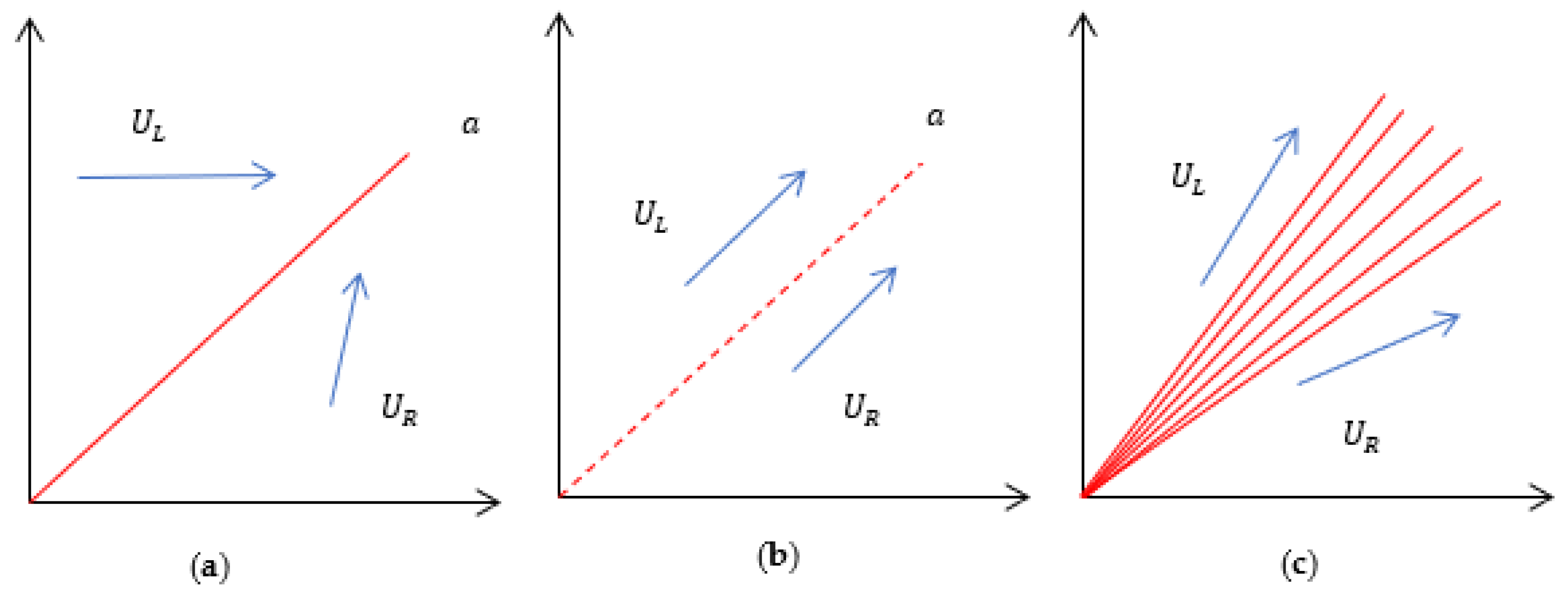
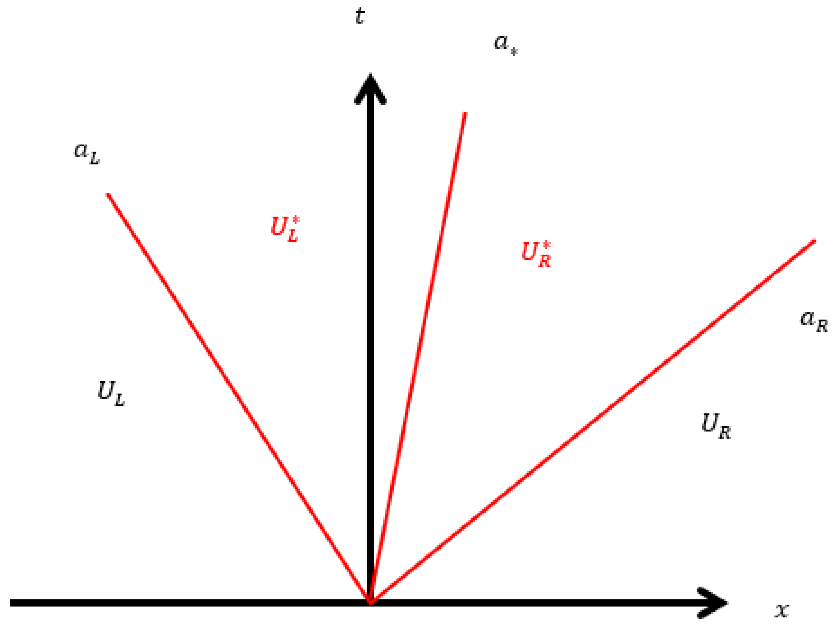
4.1.1. Approximate Riemann Solvers

HLL and HLLC Riemann solvers: Harten et al. [57] used an approximation for intercell numerical fluxes i.e., F i 1 2   and   F i + 1 2 . This literature assumes two waves ( a L , a R ) separating three constant states ( U L , U , U R ) , and by applying conservation laws in closed integral form, an approximate expression for flux can be obtained (Figure 8).
Here, the approximate Riemann solver at the interface can be represented as:
U ( x , t ) = { U L       i f x t a L   U       i f   a L x t a R U R       i f x t a R
where U = a R U R a L U L + F L F R a R a L , and the intercell flux along t is obtained as:
F ( U ) = F L a L U L 1 T U ( x , T ) d x
F = F L + a L ( U U L ) for a L 0 a R ) and F L = F ( U L ) ,   F R = F ( U R ) .
Thus, the corresponding HLL intercell flux will be:
F i + 1 2 = { F L       i f       0 a L a R F L a L F R + a L a R ( U R U L ) a R a L       i f   a L 0 a R F R       i f       0 a R
The   Intercell   flux   F i ± 1 2 reduces to the physical flux when U R = U L if there is no dissipation.
The main problem of this approximation arises from the underlying two-wave assumption, which becomes unacceptable for a larger system. Toro [1] presented a modification of this technique. Toro et al. [58] named it the HLLC model, where instead of a two-wave model a three-wave model was used. This model results in two-star regions and, hence, can tackle a large number of equations (Figure 9):
U L = 1 T ( a a L ) T a L T a U ( x , T ) d x
U R = 1 T ( a R a ) T a T a R U ( x , T ) d x
and the corresponding HLLC numerical flux:
F i + 1 2 = { F L ,                 i f   0 a L F L       i f f a L 0 a { F R         i f   a 0 a R F R                       i f   0 a R
Thus, upon integration:
F L = F L + a L ( U L U L )
F R = F R + a ( U R U L )
F R = F R + a R ( U R U R )
Roe Method: This method was first documented by Roe [59], and later modified by Roe and Pike [60]. Here, the Jacobian term J of the equation has been replaced by a constant Jacobian matrix to approximate the solution J ¯ = J ¯ ( U L , U R ) , and then substituted into the original PDE to produce the following approximate Riemann problem:
U t + J ¯ U x = 0
where the cell values are:
U ( x , 0 ) = { U L ,       x < 0 U R ,         x > 0
Thus, U i n + 1 = U i n Δ t Δ x J [ U i n U i 1 n ] for backward marching, and
U i n + 1 = U i n Δ t Δ x J [ U i + 1 n U i n ]   for   forward   marching   schemes .
Applying the vector splitting technique:
J = J + ( U ) + J ( U )
Thus, the upwinding scheme becomes:
U i n + 1 = U i n Δ t Δ x J + [ U i n U i 1 n ] Δ t Δ x J [ U i + 1 n U i n ]
and then the intercell fluxes can be represented as:
F = J U
Applying the flux splitting technique to F produces:
F = F + + F
which then produces the final upwind scheme in conservative form as follows:
U i n + 1 = U i n Δ t Δ x [ F i + 1 2 F i 1 2 ]
and the intercell fluxes are:
F i + 1 2 = F i + ( U i n ) + F i ( U i + 1 n )
Assuming hyperbolicity, F ( U ) = J ( U ) U ; thus:
F + = J + U   and   F = J U
Finally, the intercell fluxes for this problem are given as:
F ( U R ) F ( U L ) = J ¯ ( U R U L )
where the approximation for J ¯ is given as J ¯ = 0 1 J ( θ ) d θ , and θ is a parameter varying linearly between 0 and 1 along a straight path connecting U L and U R .
This process involves the conversion of a non-linearized problem to a simple linear matrix algebra-type problem. Hence this method is also known as the Roe linearization technique. In Roe and Pike’s [60] approach, the requirement of finding out J ¯ was ruled out by applying the direct averaging technique to a set of scalar quantities in order to discover the required eigenvalues and eigenvectors, as given below:
J ¯ = [ 0 1 a 2 U ¯ 2 2 U ¯ ] , where U ¯ is average velocity and given as U ¯ = ρ L U L + ρ R U R   ρ L + ρ R , while ρ L and ρ R denote the left and right values of mass density.
Thus, the corresponding eigenvalues ( λ ¯ ) and eigen vectors ( K ¯ ) are:
λ ¯ 1 = U ¯ a , λ ¯ 2 = U ¯ + a   and   K ¯ 1 = [ 1 U ¯ a ] , K ¯ 2 = [ 1 U ¯ + a ]
Osher Solver: The nonlinear Jacobian matrix J presented in Equation (13) is linearized by splitting as follows, as per Engquist and Osher [61] and Osher and Solomon [62]:
J ( U ) = J + ( U ) + J ( U )
where the first term represents positive or zero eigenvalues, and the second term represents negative or zero eigenvalues.
Thus, the flux at interface F ( U ) = F + ( U ) + F ( U ) , and F + U = J + ( U ) , F U = J ( U ) .
The initial data of the problem are denoted by:
U 0 = U L = U i n   and   U 1 = U R = U i + 1 n
hence, the corresponding fluxes can be written as:
F i + 1 2 = F + ( U 0 ) + F ( U 1 )
Performing conservation integration and simplifying the Osher fluxes can be given as:
F i + 1 2 = F ( U 0 ) + U 0 U 1 J ( U ) d U
F i + 1 2 = F ( U 1 ) U 0 U 1 J + ( U ) d U
F i + 1 2 = 1 2 [ F ( U 0 ) + F ( U 1 ) ] 1 2 U 0 U 1 | J ( U ) | d U
These integrals depend on the integral path chosen. A simplistic representation of the integration path is shown in Figure 10.
Monotonic Upstream-Centered Scheme for Conservation Laws (MUSCL): Instead of having the constant cell value employed in the first-order Godunov’s scheme, this higher order scheme assumes a linear cell value using a reconstruction technique. This method was first presented by van Leer [63,64,65] where he introduced a higher order solution of Godunov’s scheme using a TVD (total variation diminishing) scheme. The MUSCL scheme is one of the more popular higher order techniques for the finite volume method due to its higher accuracy and its somewhat simpler approach than other available higher accuracy schemes. In this method, Godunov’s scheme’s constant approximation of cell value is replaced by the reconstructed and slope-limited left and right states. Numerical fluxes are calculated at each of the cell boundaries. Those calculated fluxes act as the inputs of the Riemann solver to provide an averaged solution at the next time step. Hence, the most important part of this solver is the linear reconstruction of the cell values. Typically, the piecewise linear approximation is carried out using a central difference scheme, given as follows:
U i ( x ) = U i n + ( x x i ) Δ x ( U i + 1 U i )
for U i ( x ) = U i n + ( x x i ) Δ x ( U i + 1 U i )   x [ 0 , Δ x ] , where ( U i + 1 U i ) Δ x is slope of U i ( x ) .
The modified data will then be used to solve the generalized Riemann problem (GRP) to compute the intercell flux F i ± 1 2 .
The formation of GRP is represented as:
U t + F ( U ) x = 0
U ( x , 0 ) = { U i ( x ) ,           x < 0 U i + 1 ( x ) ,       x > 0
MUSCL Hancock Scheme: A time integration of the hyperbolic portion of the governing equation is now represented as:
x i 1 2 x i + 1 2 U ( x , t n + 1 ) d x x i 1 2 x i + 1 2 U ( x , t n ) d x = t n t n + 1 [ F i 1 2 ( t ) F i + 1 2 ( t ) ] d t
A modification to this scheme was presented by van Leer [66]. In this method, the evolution of U i L and   U i R , which are the flux vectors at the cell interfaces, by time 0.5 Δ t is given as:
U i L ¯ = U i L + 0.5 Δ t Δ x [ F ( U i L ) F ( U i R ) ]
U i R ¯ = U i R + 0.5 Δ t Δ x [ F ( U i L ) F ( U i R ) ]
The piecewise Riemann problem is represented as:
U ( x , 0 ) = { U i L ¯                 ,   x < 0 U i R ¯                   ,   x > 0

Limiters

A suitable limiter function is used to keep the cell values within the cell limit. Therefore, proper limiter functions are implemented as per the requirement. The limiter function limits the spatial derivative values to realistic ones, in order to protect the solution from unreliable convergence and keep the oscillations within acceptable limits. The TVD fluxes with the application of a limiter function can be represented as:
F i + 1 2 = F i + 1 2 L O W ϕ ( r i ) ( F i + 1 2 L O W F i + 1 2 H I G H ) F i 1 2 = F i 1 2 L O W ϕ ( r i 1 ) ( F i 1 2 L O W F i 1 2 H I G H )
where F i + 1 2 L O W , F i + 1 2 H I G H ,   and   ϕ ( r ) are low- and high-resolution flux limiter functions and the slope of the limiter function, respectively. In principle, the flux is calculated by Equation (63); however, in the case of several equations, the limiter evaluation is not unique. For this reason, the variables are usually limited, and the fluxes are calculated based on the limited variables.
The ratio of successive gradients r i = U i U i 1 U i + 1 U i and ϕ ( r ) 0 , which represent that for ϕ ( r ) = 0 flux value changes to a low-resolution scheme, and for ϕ ( r ) = 1 flux value changes to a high-resolution scheme. Various limiters have been presented in the works of Toro [1] and Guinot [10], which can be used to reconstruct the cell value for water hammer problems.
Pal et al. [53] used MINMOD, since it produced the best results compared to other methods. In the MINMOD method, numerical flux in the predictor step is given as:
U i 1 2 = U i n 0.5 Δ x   minmod ( σ i n , σ i 1 n )
U i + 1 2 = U i n + 0.5 Δ x   minmod ( σ i n , σ i 1 n )
where σ i 1 n = U i n U i 1 n Δ x , σ i n = U i + 1 n U i n Δ x and minmod ( σ i n , σ i 1 n ) = { σ i n   i f   ( | σ i n | < | σ i 1 n | )   and   σ i n σ i 1 n > 0 σ i 1 n   i f   ( | σ i n | > | σ i 1 n | )   and   σ i n σ i 1 n > 0 0   i f   σ i n σ i 1 n < 0
In the corrector step:
U R n + 1 = U i + 1 2 + 0.5 Δ t Δ x [ F ( U i 1 2 ) F ( U i + 1 2 ) ]
U L n + 1 = U i 1 2 + 0.5 Δ t Δ x [ F ( U i 1 2 ) F ( U i + 1 2 ) ]
The cell interface fluxes are obtained using Equations (64) and (65). Figure 11 shows different types of limiter configurations with slopes in the Sweby diagram [67]. Figure 12a,b represents MUSCL reconstruction for a single cell and three cells, respectively. It is wort mentioning that in the case of Riemann solvers, the amount of dissipation depends on the difference between the left and right states. The figure clearly shows that a first-order method produces more dissipation.
A piecewise quadratic reconstruction of the equation as given below was presented by Woodward and Colella [68] and Woodward and Colella [69]:
U i ( x ) = U i n + x x i Δ x χ i 1 + 3 ψ 2 ( Δ x ) 2 [ ( x x i ) 2 ( Δ x ) 2 12 ] χ i 2
where χ i 1   and   χ i 2 are associated with first- and second-space derivatives of U i ( x ) and ψ = 1 3 . This is a third-order accurate space discretization, and is popularly known as the piecewise parabolic method (PPM). Another novel method, named the piecewise linear interpolation method (PLIM), was also presented in connection with the analysis of the study of water withdrawal and return after volcanic activity, but has found no use beyond nuclear safety applications [70]. It should be noted that numerical smearing cannot be completely removed in higher order schemes. A nonlinear method with adaptive multiresolution analysis is required to remove the oscillations [71].
Among other approaches for improving problems associated with the non-conservative solution of the hyperbolic problem, the flux-corrected transport (FCT) technique was introduced by Boris and David [72]. This approach essentially employs a finite difference algorithm, and finds its primary application in the conservative solution of the Euler equation in gas dynamics when seeking to capture shocks and discontinuities. The Eulerian FCT algorithm was nicknamed SHASTA (sharp and smooth transport algorithm) and consisted of two stages: (a) the transport stage (predictor stage), and (b) the anti-diffusion stage (corrector stage). This kind of higher order method requires an artificial viscosity term in the momentum equation to prevent, or at least limit, numerical dispersion. However, this method has little application within the water hammer community.
Hwang and Chung [73] utilized the FV technique for water hammer, without neglecting the advective term, and using the conservative form with the density as unknown instead of the pressure head. Szydlowski [74,75] used a second-order accurate FVM scheme for one-dimensional transient flow in a pipeline using a Riemann solver with the Roe linearization technique, in order to analyze the effect of water hammer in a single pipeline system. Szydlowski [75] represented the numerical flux at the interface in a similar way to Equations (49)–(51). Increments in pressure and mass flow between boundaries were represented by Δ U , which is calculated by averaging their values at the left and right states. Estimation of Δ U is carried out by using the cell-centered values of U i and U i + 1 as left and right state cell values, and using MUSCL scheme extrapolation for ensuring second-order accuracy. Although this method produced predictions in close agreement with analytical results, its large deviation from experimental results demonstrated its inability to capture the additional energy dissipation processes that often influence transient events in real pipe systems.

4.1.2. Flux Vector Splitting (Boltzmann Approach)

Along with Godunov’s scheme, which uses the Riemann solver (flux difference splitting) technique, the flux vector splitting method also gained popularity due to its lower computational effort requirements and simpler, more efficient application. Though popular, it suffers from some poorer discontinuity resolution, which makes it a poor candidate for high-shock-wave problems, such as water hammer. Most notable work on developing this method was undertaken by Sanders and Prendergast [76], Steger and Warming [77], and van Leer [78,79]. The upwind differencing is carried out, and the final forms of the flux vectors and corresponding intercell fluxes are represented as:
U i n + 1 = U i n Δ t Δ x [ F i + 1 2 F i 1 2 ]
and:
F i + 1 2 = F i + ( U i n ) + F i ( U i + 1 n )
For more details about this method, readers are advised to consult Sanders and Prendergast [76], Steger and Warming [77], and van Leer [78,79].
Boundary treatment: For the computation of boundary fluxes at x = 0   and   x = L , most popular techniques extend the computational domain beyond the physical domain. These additional cells are called ”ghost cells”, ”fictitious cells”, or ”virtual cells” [1]. They exist solely for handling boundaries, and do not necessitate extra equations at the boundaries. Two cells, I 0   and   I m + 1 , are taken as the two extreme point fictitious nodes adjacent to real nodes I 1   and   I m , and the corresponding Riemann problem is solved for finding the Godunov fluxes F 1 2   and   F m + 1 2 .
Some potential physical boundary conditions that can arise for the proposed case are: (1) transmissive boundary, which allows the passage of waves without affecting the boundary used as the far-field boundary; and (2) reflective boundary, or valve boundary, which simulates a reflective impermeable boundary at x = L . The valve boundary condition represents the specific relation of discharge rate to time due to variable valve closure. A detailed description of those boundaries and their treatments is provided in Toro [1], and hence, is excluded here.

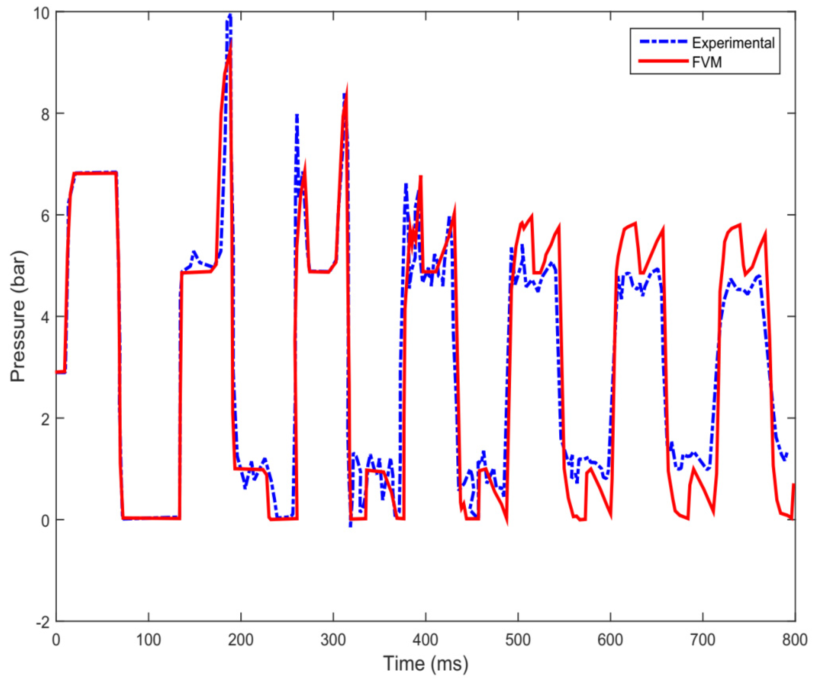
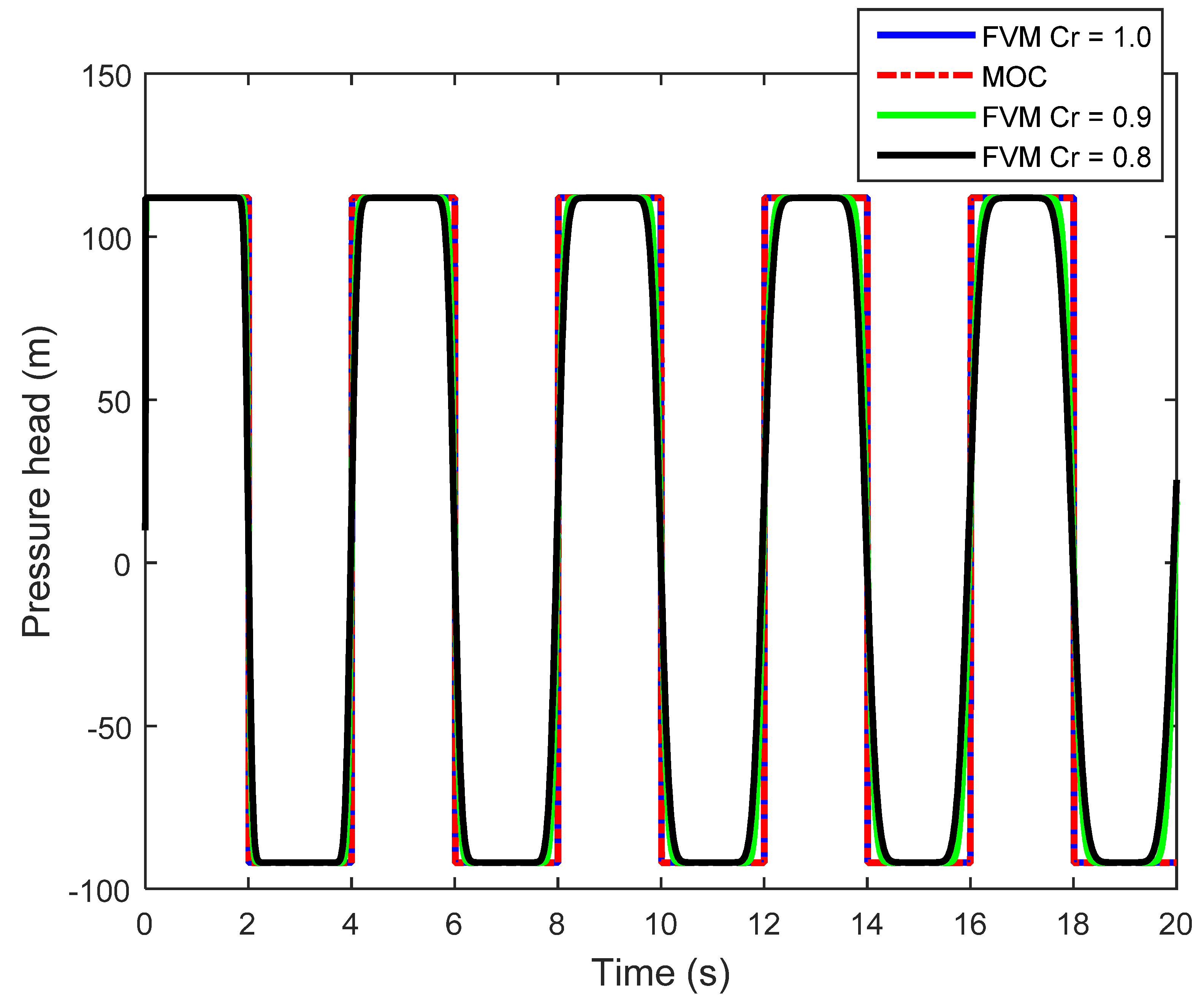
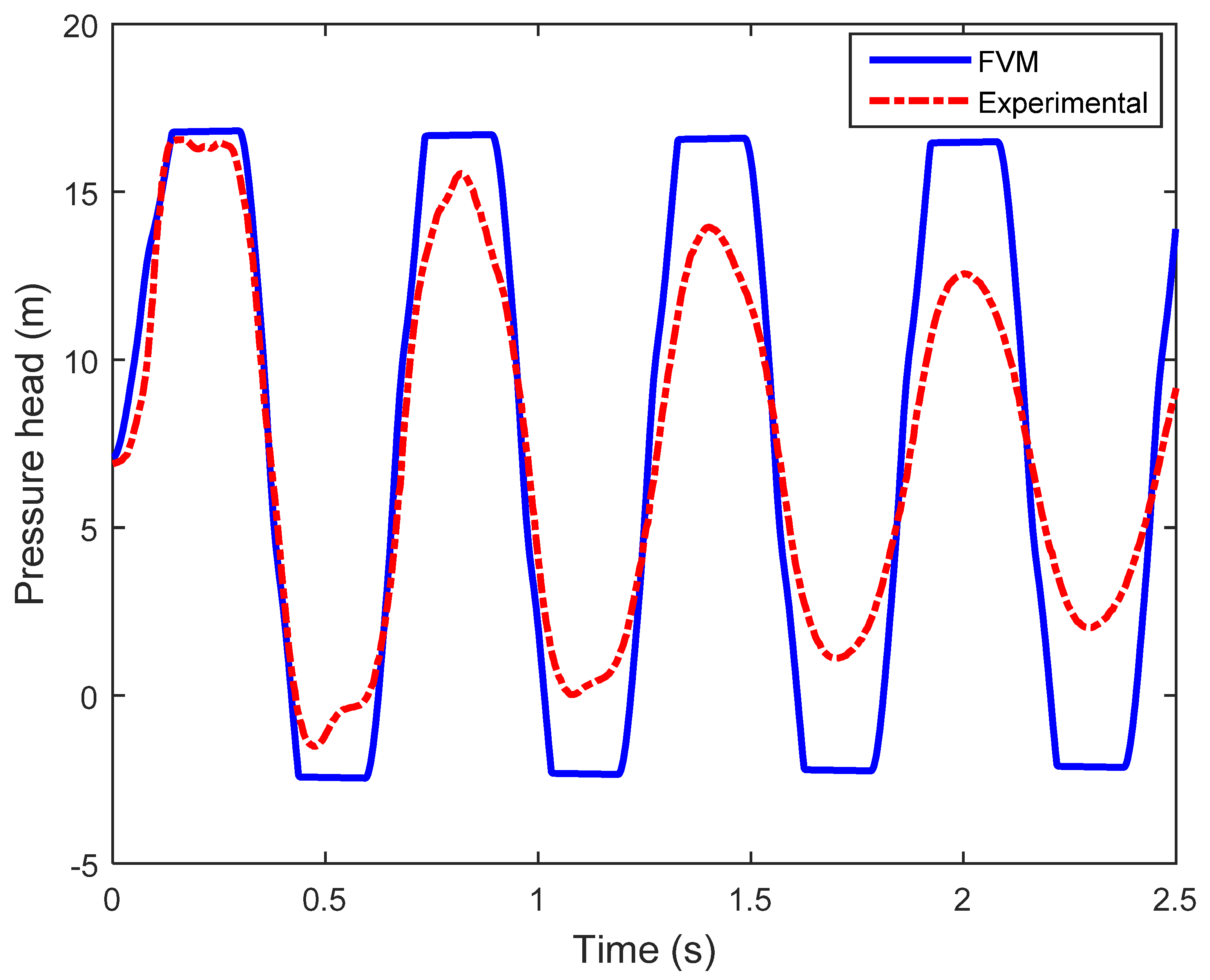
4.2. Finite Volume Method (FVM) Applications
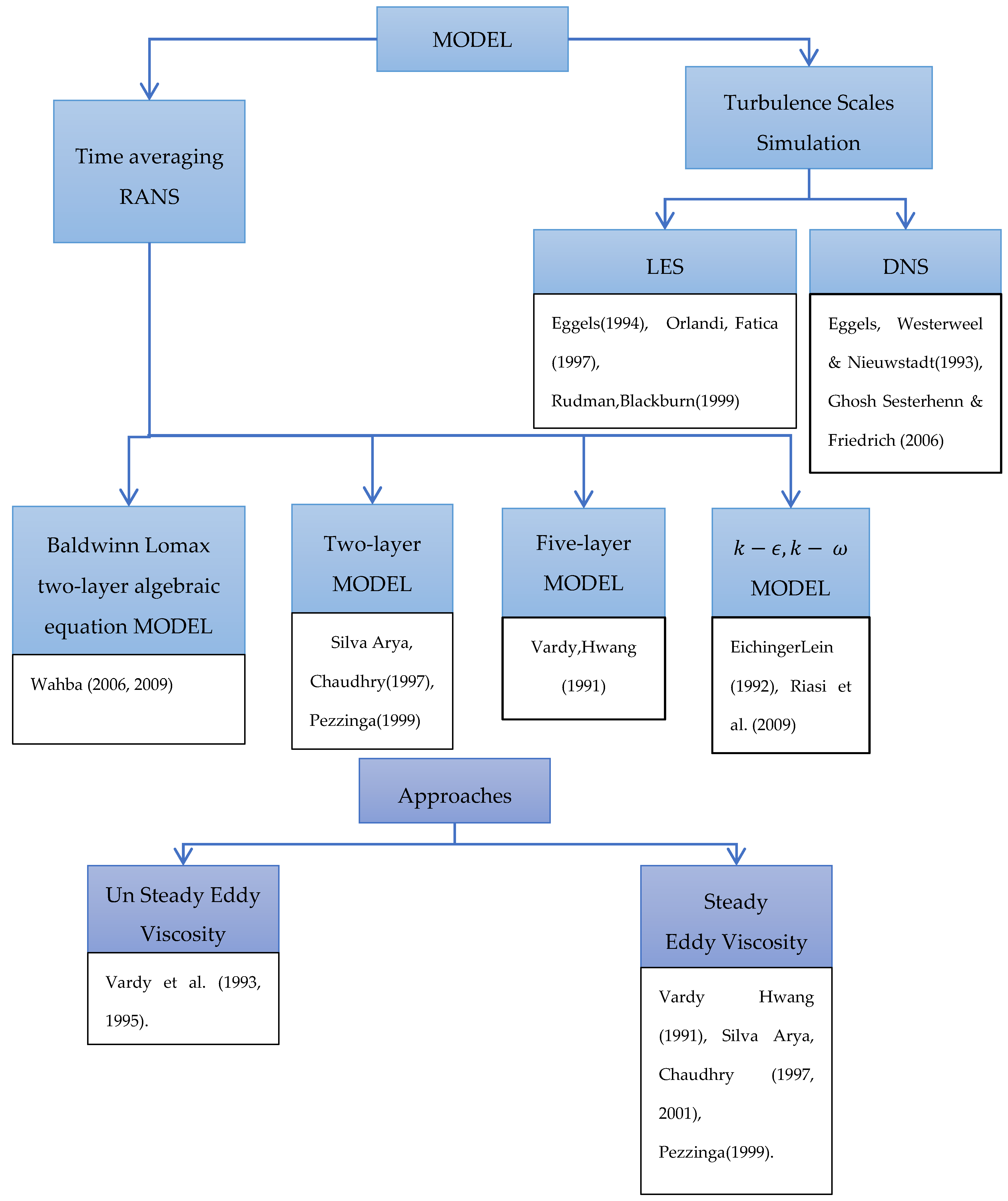
Zhao and Ghidaoui [80] further investigated applying the FV technique based on mass and momentum conservation principles for water hammer modelling. They considered an MOC-type system of two pipes connected in series with a valve and a reservoir. They solved the numerical flux by the exact solution of the Riemann problem using both first- and second-order Godunov’s schemes. The advective term was calculated by the arithmetic mean in order to solve the Riemann problem. They considered the conventional case as zero, and then compared the solutions. Finally, they concluded that although the first-order MOC, like the Godunov’s scheme, showed high numerical dissipation with reduced accuracy, the second-order Godunov’s scheme with a MINMOD limiter significantly increased the accuracy and efficiency. Although a second-order formulation was used for interior nodes, a first-order formulation was applied at the boundaries. For wave propagation, the first-order interpolation on the boundaries cannot be of vital importance, although it certainly affects the results. Later, the same authors [51] sought to improve the scheme by using the MUSCL–Hancock method with a virtual cell technique at the boundary, thus maintaining a second-order accuracy throughout the computational domain. In this scheme, the left and right states of discontinuity at the ith cell are expressed as follows:
U L n + 1 / 2 = U L n + Δ t 2 Δ x [ F ( U L n ) F ( U R n ) ]
  U R n + 1 / 2 = U R n + Δ t 2 Δ x [ F ( U L n ) F ( U R n ) ]
where Δ t and Δ x are temporal and spatial steps. This method showed improved accuracy and efficiency for large pipe networks compared to the previous method [51,80,81].
Yazdi et al. [82] used a similar approach for the second-order Godunov’s scheme in order to develop a one-dimensional coupled model based on Riemann solutions with a similar type of arrangement, and compared the results with analytical solutions. They concluded that the second-order scheme agreed closely with the analytical method when the Courant number ( C r ) was equal to one, but showed some numerical dissipation for lesser Courant numbers. Leon et al. [83] proposed a virtual cell technique for the treatment of boundaries. Later, Leon et al. [84] further continued their work and introduced an FV shock-capturing scheme for both one- and two-phase flows. They compared the results between the FV model and the available MOC model for single-phase flow, and concluded that the MOC is suitable for C r   = 1, but for C r   < 0.95 the efficiency and accuracy of the shock-capturing FV scheme proved to be significantly better. According to Leon et al. [84], a comparison of numerical results between the FV scheme and the fixed-grid MOC for two-phase flow demonstrated significant advancement in the efficiency of the FV method.
Kerger et al. [85] developed a unified numerical model for all types of flows, such as pressurized flow, open-channel flow, and mixed flow. In their method, Kerger et al. [85] used the Preissmann slot technique [86] with a first-order Godunov’s scheme based on the exact Riemann solver to solve the pressurized flow. The comparison between analytical, experimental, and numerical results was good, but numerical oscillations were present when the wave celerity was large. A 2 × 2 system for water hammer was solved by Guinot [46] using a higher order piecewise parabolic scheme along with Godunov’s scheme for a simple single-pipe system. A six-point-in-space model was proposed along with a number of boundary condition treatments with a virtual cell technique. Although it showed improved accuracy over the MOC, it proved that the ill-treated boundary condition could also result in degraded accuracy for highly accurate and efficient schemes [46]. Daude et al. [87] used the FVM model for simulating water hammer events with column separation. This experimental case corresponds to water hammer with moderate cavitation.
The good agreement between the numerical pressure history at the valve and its experimental counterpart is clearly shown in Figure 13. The primary pressure peak was generated by the instantaneous closure of the valve, and has a value equal to the Joukowsky value ≈ 6.83 bar. Afterwards, cavitation occurs at the valve due to the reflection of the rarefaction wave at t = 57 ms. The collapse of the vapor pocket at t = 120 ms generates the secondary water hammer wave. The superimposition of the primary and the secondary water hammer transients produces a pressure peak with a magnitude of 10.1 bar at t ≈ 171 ms, which is higher than the Joukowsky pressure. The end of this pressure pulse corresponds to the arrival of the second water hammer wave at t ≈ 177 ms. This very short duration of 6 ms pressure pulse demonstrates the accuracy of the FVM. The three last pressure peaks were overestimated due to the inclusion of only steady-state friction. However, the timing of the pressure waves was well retrieved by the FVM, even for the later water hammer events.
In a further study, a validation exercise was undertaken for first-order and second-order FVMs as per the methodology presented in Pal et al. [53]. A frictionless pipe system with a large reservoir at the upstream and a valve at the downstream was considered. The internal diameter D and length L of the pipe were taken as 0.04 m and 1000 m, respectively. Initial steady velocity V 0 (i.e., prior to valve closure) was taken as 1.0 m/s, while constant upstream reservoir head H 0 was taken as 10 m. The wave celerity was taken as 1000 m/s, with a mass density of water ρ = 1000 kg/m3. The domain was spatially discretized into 100 segments. Total simulation time was considered to be 20 s after the valve closure, with a constant time step Δ t of 0.01 s. The same space and time discretization was adopted for the MOC. The simulation results are presented in Figure 14. Both the first-order and second-order FVM (MUSCL–Hancock method) were considered, and their results were the same. Therefore, both are represented as FVM in Figure 14. The computational times of the first-order FVM and the standard MOC are comparable. However, the computational time of the second-order FVM is an order of magnitude more than the MOC. The comparisons in Figure 14 demonstrate that the results of the MOC and the FVM are the same for C r = 1. However, for C r values less than unity, such as C r values of 0.9 and 0.8, the FVM maintains excellent phase accuracy; however, as the Courant number decreases, the accuracy decreases, as shown by the rounding of the sharp corners of the exact solution, although the error is small. This particular characteristic of the FVM is highly advantageous in cases where wave celerity changes along the pipeline due to either air pockets or, for instance, a change in the pipe wall thickness or pipe diameter.
These results also demonstrate that the first-order FVM is as good as the MOC, which was also demonstrated by Pal et al. [53]. In addition, the FVM method [53] was also validated with experimental data, as demonstrated by USC-2 in the work of Reddy et al. [88]. The pipe system consisted of 156-m-long copper pipe of 0.025 m diameter. The estimated values of wave velocity and the Darcy–Weisbach friction factor were 1050 m/s and 0.026, respectively. The experimental flow conditions were initial steady-state flowrate and inlet pressure head equal to 4.8 × 10⁻⁵ m3/s and 7.15 m, respectively. The valve was rapidly closed in 0.14 s, and it was modelled by the MOC and the first- and second-order FVMs. Since the MOC and FVM results are identical, only the FVM and experimental data are presented in Figure 15. These results demonstrate that the dissipation in experimental pressure is quite high, whereas numerical modelling with steady-state friction underpredicted the decay. This can be addressed by implementing either IAB (instantaneous acceleration-based) models or by weighting function-based unsteady friction models. Finally, the similarities between the FVM data, MOC data, and experimental data suggest the suitability of the FVM for modelling water hammer flows.

5. Two-Phase Flow

Multiphase flow in pipe systems is commonly observed in various industrial fields, whether requiring of different types of fluids or different phases of the same fluid. In such cases, both steady-state and transient predictions of flow and hydraulic shocks are crucial. A critical problem associated with the application of multiphase analysis is its high computational expense [89]. Taitel [90] presented a model that treats only the liquid as fully transient, whereas the gas is assumed to be in a quasi-steady state. However, such a model is invalid for large shocks. The early model was later modified by Minami and Shoham [91], who advocated for an implicit computational scheme, and suggested an improved flow regime transition model. Li [92] considered the continuity equation to be transient, but employed the momentum equation as a quasi-steady-state representation. Choi et al. [93] suggested a two-phase transient model with a modified continuity equation, and treated momentum as an extended drift-flux equation. Oloruntoba and Kara [94] presented a transient model based on the Navier–Stokes equations, without neglecting the convective term.
One of the most important applications of two-phase transient analysis is the safety analysis of nuclear reactors. Water hammer and two-phase transients can induce failure and accidents at such plants, making transient analysis and prediction of utmost importance. For the analysis of the safety of nuclear reactors, a number of computational techniques were introduced in the early 1980s. The two-phase flow equations represent a comprehensive presentation of the flow, but lead to a non-hyperbolic governing system. Nevertheless, the hyperbolicity can be established with a special treatment of the phase interaction terms, if one assumes equal velocities or equal temperatures and the number of equations drops. With equal velocities, the system of governing equations becomes hyperbolic. A few notable examples among those codes used for thermohydraulic analysis are THERMIT, TREMOLO, RELAP5, RETRAN, CATHARE, TRACE, etc. [95,96,97,98,99,100]. The basic equation of multiphase flow used in reactor safety analysis is in the following form [101]. The continuity equation:
ρ a t + x ( ρ a v a ) = M a ˙
where mass conservation is represented as M ˙ = 0 and a = l , g , where l   and   g are liquid and gas phases, respectively.
The momentum equation with an assumption of equal interfacial pressures is as follows:
( ρ a v a ) t + x ( ρ a v a v a ) + α a p x = ρ a g + A a b ¯ D a b g ( v a v b ) + M ˙ a v a ˘ + F x a
The study of nuclear reactors requires consideration of the energy conservation, as follows:
( ρ a S a ) t + x ( ρ a v a S a ) = ( ω a T a )
where ρ a is the partial density of phase a, α a is the volume fraction of phase a,   v a is the phase velocity, M a is the rate of formation of phase a, p is the pressure, A a b ¯ is the interphase area per unit volume, D a b g is the drag coefficient multiplied by the density and the absolute value of the velocity difference, v ˘ a is intrinsic velocity associated with the source term, F x a is the wall friction for phase a , S a is the entropy per unit mass, T a is the phase temperature, and ω a is the rate of dissipation of energy due to friction and mass transfer.
The right-hand sides of the total energy equations for both of the phases are complicated, and contain terms rising from Equation (72) and heat transfer. All of these are grouped to the RHS term of Equation (73). Since the original variable is ρ a ( e + ( v a ) 2 / 2 ) , and the pressure work is usually included in the convection term to form a phase enthalpy, the actual equations that are solved may differ from Equation (73). The equation of state for phase a is given as ρ a = ρ a ( S a , p ) .
RELAP(1–5), developed by the Nuclear Regulatory Commission, is widely considered to be one of the best estimating codes among those in use for light water reactors. It is essentially a one-dimensional, two-phase, non-homogeneous, and non-equilibrium model based on a partial implicit scheme that provides prime importance to mass and energy conservation over momentum conservation. RELAP(1–5) is popular due to its specific adaptation to this application.
Tiselj and Petelin [102] used a shock-capturing two-phase model based on the RELAP5 code, consisting of non-hyperbolic partial differential equations of mass momentum and energy balance. They used a basic averaging technique for the solution of the Jacobian, using conservative and non-conservative basic variables, and they used the method for the solution of a two-phase shock tube problem.
Based on the method developed by Tiselj and Petelin [102], Melikhov et al. [103] and Gale et al. [104] proposed a state-of-the-art WAHA (water hammer) code—which is a one-dimensional water hammer model—to solve two phases, and they found good agreement with experimental measurements. The WAHA code is a six-equation model based on mass, momentum, and energy conservation. The model is mainly used for calculating hydraulic forces on the piping system during a water hammer event.

6. Development of Other Approaches

Various numerical schemes have also been used to analyze water hammer problems. For example, an MOC-like scheme inspired by the graphical method that tracks wavefronts is often called the wave plan or wave characteristic method [105]. Since the accuracy of this approach is first-order both in space and in time, a finer discretization is required in order to achieve high accuracy, but internal sections are largely avoided. The key assumption associated with this method is that friction is concentrated in a virtual orifice located at the midpoint of each pipe.
Verwey and Yu [106] used a fourth-order scheme to describe steep pressure fronts accurately. Using three time levels and two spatial points better represented the boundary conditions. Chen et al. [107] modelled water hammer by using optimal boundary control for the nonlinear hyperbolic PDEs describing closed-conduit flow. They used a method of lines to solve the converted ordinary differential equations (ODEs), thus reducing numerical dissipation and associated fluctuations.

6.1. CFD Schemes

Zhang et al. [47] improved a Lax–Wendroff method (LWM) [1]-based approach for a gravitational reservoir pipe system with air entrainment, without neglecting the convective acceleration terms. Comparison of their experimental data with numerical data showed that although the LWM scheme accurately predicted the maximum pressures similarly to the MOC, it underpredicted the attenuation of the water hammer waves—something that they attempted to control through an additional friction function. Szymkiewicz and Mitosek [108] used the Galerkin-based finite element method (FEM) for simulating water hammer problems. The FEM is not favorable for modelling water hammer problems, for reasons such as (1) stability criteria still needing to be satisfied, (2) accuracy being no better than that of the MOC, (3) requiring excessive computational resources, and (4) difficulty to program. However, FEM is the most sought-after method for modelling water hammer problems with fluid-–structure interaction (FSI).
Modelling of the water hammer phenomenon for dynamic characteristics within a turbine is impossible using the classical 1D MOC or FVM schemes, and such applications require more extensive 3D grids and turbulence models. Several commercial pieces of software for turbulence modelling available today can be effectively used for this type of study. Some well-known and well-applied turbulence models currently in use are FLUENT and CFX (https://www.ansys.com (accessed on 1 June 2021)). Commonly, user-defined function and 1D MOC coupled with a 3D CFD model are used for providing the complex input and boundary conditions for turbine transient problems [109]. Yuan et al. [110] presented another approach for coupling 1D MOC with a 3D CFD model, and validated surge tank oscillation, which was further modified by Fan et al. [111], Wu et al. [112], and Zhang et al. [113]. Yan et al. [114] and Yin et al. [115] used CFX and FLUENT (https://www.ansys.com (accessed on 1 June 2021)) for 3D simulation of compressible water hammer problems, in which a hydroelectric generator suddenly rejected its load in order to safeguard itself from an accident, and created a hydraulic transient in the penstock. Zhang et al. [116] modelled a transient associated with Francis turbines during load rejection by using a novel 1D–3D coupled method for a compressible liquid model, and compared their data effectively with standard classical MOC models.

6.2. Lagrangian-Based Numerical Methods

Recently, Lagrangian-based numerical methods such as the lattice Boltzmann method (LBM) and smoothed-particle hydrodynamics (SPH) are gaining popularity for modelling unsteady flows. The LBM and SPH models are meshfree, in which governing equations are solved at any point in the space–time plane to find local solutions without explicitly using previously stored data. In particular, the LBM is a modern approach in CFD, which belongs to a class of kinetic theory. The LBM is suitable for modelling (1) multiphase flows including tiny droplets and bubbles, (2) flow through porous media, (3) flow through complex geometries, (4) coupled flow with heat transfer, and (5) cardiovascular hemodynamics. The LBM was considered by Cheng et al. [117] for unsteady flow, and later a practical and simple implementation was carried out by Wu et al. [118]. Budinski [119] modelled a one-dimensional water hammer using the LBM, in which the grid was independent of the Courant number. To achieve this, the governing equations were transformed using an alternative coordinate system suitable for an adaptive grid. The LBM simulation was validated using the MOC for water hammer resulting from pump tripping, with excellent agreement. Furthermore, Louati et al. [120] modelled a two-dimensional water hammer using the LBM, and compared the results with a fifth-order FV scheme. According to Louati et al. [120], the higher order FDM and FVM are challenging to implement with complex boundary conditions such as pumps, turbines, and valves.
Overall, LBM schemes are a viable alternative. Louati et al. [120] observed that the LBM is computationally fast and equally accurate to the MOC for low-frequency water hammer waves. However, the LBM becomes unstable and inaccurate for high-frequency water hammer waves. The LBM is faster and more accurate, whereas the SPH method is more stable and has broader applications, such as one-dimensional wave propagation, slug flow, sediment flushing from sluice gates, and three-dimensional dam breaking.
Hou et al. [121] were the first to use SPH for simulating the rapid filling of a pipeline. The 1D water hammer equations were used along with a dynamic SPH pressure boundary condition. This method reduced the problem of boundary deficiency associated with conventional SPH methods. In this approach, a set of particles is introduced at the upstream boundary, depending on the smoothing length, with predefined velocity and pressure. As those particles are flowing through the system, the next set of particles is generated. The same procedure is also adopted for the downstream boundary condition. A cubic spline kernel function approximates the spatial derivatives. Good agreement is observed between SPH and rigid column theory, especially in the deceleration phase of the filling. Hou et al. [122] utilized a corrective smoothed-particle method (CSPM) to simulate water hammer in a simple reservoir, pipe, and valve system. A corrective kernel estimate of SPH approximated the spatial derivatives in the water hammer conditions. For the transient derivatives, the Euler-forward time joining calculation was utilized. An artificial viscosity term was added to the momentum equation in order to prevent numerical dispersion. Hou et al. [122] found that the CSPM outcomes are in good agreement with the results acquired by the MOC for three different cases. A parametric examination provides knowledge about the impacts of particle conveyance, smoothing length, and kernel work. Although this method is inefficient for traditional water hammer systems, it is a key step representing the free-surface water hammer problem. Furthermore, Hou et al. [123] used a second-order accurate CSPM to model dynamic interaction between air bubbles and water in a dead-end pipe. In this method, a new water particle is introduced at the upstream when the most upstream particle distance is more than one particle size from the inlet. Similarly, as soon as the most upstream particle leaves the inlet, it is deleted in backflows. This method can introduce an error due to the mispositioning of the upstream particle, but the authors emphasize that this effect will be negligible for smaller particles. Hou et al. [123] argued that this method is accurate, efficient, and straightforward for a water hammer with a nonlinear downstream boundary condition, such as a compressible air pocket at the dead end. Although a few researchers have obtained good results with SPH for modelling the water hammer, the method is still awkward for the implementation of complex boundary conditions. Furthermore, there are a few advanced schemes—namely, FEM, LBM, etc.—that can be used for transient analysis, but those are not of much relevance to practicing engineers.

6.3. Two-Dimensional Numerical Schemes

Although one-dimensional schemes are easy to understand and implement, and when used appropriately achieve excellent accuracy, stability, and monotonicity, their use in multidimensional problems with anisotropic turbulence is difficult and error-prone. In addition, 1D schemes for complex devices like pumps and turbines, and even unsteady friction, have their limitations. Therefore, in recent times, considerable effort has been invested into developing two-dimensional transient pipe flow models for calculating Reynolds shear stress.
Shear stress τ in Equation (17) is a summation of viscous and Reynolds stresses. The Reynold stress ρ u v ¯ is dominant in turbulent flows, and it can be computed using an appropriate turbulence model based on RANS equations. For water hammer applications, the most popular method for turbulence modelling is an algebraic model, where the eddy viscosity is expressed as a function of the flow field. Details of various turbulence models based on the same principle for water hammer phenomena, their theories, and their constraints can be found in the works of Vardy and Hwang [12], Eichinger and Lein [124], Silva-Araya and Chaudhry [17], Silva-Araya and Chaudhry [125], Pezzinga [14], and Ghidaoui et al. [126]. Vardy and Brown [127] followed Zielke’s methodology by assuming an idealized turbulent flow with eddy viscosity varying linearly in the outer layer, which enabled an approximate analytical relation between the decay of wall turbulence and the sudden change in the velocity. Vardy and Brown [127] used the MOC and a five-layer turbulence model in the radial direction. Silva-Araya and Chaudhry [17] proposed a two-layer turbulence model in which Prandtl’s mixing-length approximation was used for estimating eddy viscosity at the inner and outer layers. Pezzinga [14] implemented the mixing-length hypothesis in a quasi-two-dimensional (2D) model in order to simulate transient flows in simple pipe networks. A comparison between two popular algebraic models—two- and five-layer turbulence models—was presented by Ghidaoui et al. [126,128], showing that the two-layer model is preferable for unsteady flow. Vardy and Brown further improved their method by assuming the bilinear approach of eddy viscosity in the outer region, i.e., steady increase in the outer region close to the wall and an approximately uniform eddy viscosity in the core region. Moreover, Zhao and Ghidaoui [80] improved the speed and stability of the Vardy and Hwang [12] model by decoupling the overall solution matrix into two tridiagonal matrices consisting of pressures and velocities, respectively.
Furthermore, Zhao and Ghidaoui [122] developed a k ε turbulence model based on the work of Fan et al. [105] for water hammer flows. Zhao and Ghidaoui [129] used the MOC to solve continuity and momentum equations for water hammer equations. Recently, numerical models based on a combination of the Runge–Kutta methods and two-equation turbulence models are receiving attention. Wahba [130,131] modelled two-dimensional unsteady pipe flow using mixing-length Baldwin–Lomax and Cebeci–Smith turbulence models, along with the Runge–Kutta method, to integrate mass, momentum, and central differencing for spatial derivatives. Riasi et al. [132] used the fourth-order Runge–Kutta scheme along with k ω and k ε turbulence models for studying the behaviour of the unsteady turbulent flow. Both of these models reported good consistency with the experimental results. Later, some effort was also made in using LES (large eddy simulation), but this 3D-based model requires significantly smaller cells [133]. Direct numerical simulation (DNS) resolves all scales, including Kolmogorov scale eddies, without using any empirical model. DNS solves full Navier–Stokes equations, and hence, is computationally very intensive, although recent developments in computational power and parallelization of processing are encouraging for the use of DNS. However, DNS remains applicable only to small Reynolds numbers (Reynolds numbers less than 5000), small pipe lengths, and small diameters. Therefore, the use of the DNS technique has not gained sufficient popularity in application to transient analysis. A few studies that deal with the techniques include those by Eggels et al. [134] and Ghosh et al. [135], but most are not directly related to transient analysis. In order to obtain a representative ensemble, a number of simulations are required, which is often computationally infeasible. In recent years, some researchers [136,137,138] have used 3D CFD models for solving valve-induced water hammer based on MOC code. Mahdizadeh [139] used a modified flux wave approach and two-dimensional finite volume method with a ν 2 ¯ f ¯ turbulence model, and got identical results for experimental damping. Finally, it is clear from the literature presented here that two- and three-dimensional models can accurately predict frictional damping. Mandair et al. [140] developed a tool called integrated total energy (ITE) for CFD modelling to analyze energy dissipation during water hammer. Figure 16 illustrates a brief review of all of the turbulence models explained previously for a better understanding. The available turbulence models for the Reynolds shear stress are based on either steady-state or unsteady-state eddy viscosity distribution. The research approaches [130,131,132,133,134,135,141,142] based on time-varying or time-invariant eddy viscosity distributions are given in Figure 16.

6.4. Modelling of Unsteady Flows in Pipe Networks

The presence of complex configurations of pumps and pipe connections in networks gives rise to different types of flow disturbances. Thus, it is often vital to consider pipe network design along with the study of the unsteady flow itself. Karney and McInnis [143,144] presented a simple algebraic framework for a simple pipeline network system, and proposed an explicit algorithm known as EED (external energy dissipator). Cabrera et al. [145] suggested that there are two types of basic models available for network analysis: (a) dynamic models (inertial and non-inertial), and (b) static or steady-state models. Among those models, only the elastic inertial model is the best for modelling water hammer in pipe networks. Ani and Khayatzadeh [146] introduced an interpolation technique (based on the finite difference method) coupled with a fixed-grid MOC to capture the exact solution where the Courant’s condition does not satisfy the simple MOC at any specific location of the pipe network system. Gad and Mohammed [147] proposed an efficient technique for simplifying the water supply network using two different model networks based on numerical simulations carried with Water Hammer and Mass Oscillation (WHAMO) software (www.cecer.army.mil/usmt/whamo/whamo.htm (accessed on 1 June 2021)). They suggested hydraulic equivalence and demand concentration for the simplification.
Rigid water column (RWC) models are sometimes useful for modelling unsteady, incompressible flow in pipe networks. Their general applicability falls between the inertia model and the quasi-steady model [148,149]. Todini [150] provided an effective quasi-steady model GGGA (generalized global gradient algorithm), but it was not helpful for inertia-enabled networks. Similar works were also carried out by various researchers including Shimada [151], Onizuka [152], Holloway [153], and Ahmed [154], and work on the application of RWC to a pressurized pipe was conducted by Islam and Chaudhry [155] and Nault and Karney [148,149]. Todini and Rossman [156] produced systems of nonlinear formulations for looped water distribution networks, and they used methods such as the NR (Newton–Raphson) method and LT (linear theory) to covert those into linear formulations, which show faster convergence rates than the nonlinear formulations. Nault and Karney [148] presented a modification of the global gradient algorithm (GGA) to produce the RWC GGA algorithm. The RWC CGA considers the inertial effects of pressured flow and improves the model applicability for simulating water hammer in the pipe networks. However, this model showed a higher computational cost than the conventional GGA method. Nault and Karney [149] proposed a combined GGGA and RWC GGA, known as HGGA, along with a variable time step approach to include the inertial effect of pressurized flow. This method is computationally costly, but it is highly accurate for dynamic hydraulics.
Jung and Karney [157] compared different water hammer models—including rigid water column analysis, quasi-steady analysis, and the Joukowski approach—based on the physical properties of the models, predictions of actual data, and stability and accuracy. Finally, they proposed some guidelines for the suitability of using any particular model according to the need. Nault et al. [158] proposed a flexible generalized characteristics method (GCM) by coupling a high-resolution MOC and a low-resolution WCM (wave characteristics method), which can generate accuracy similar to the MOC at a better computational cost. Later, Nault and Karney [159] proposed a novel adaptive hybrid transient model (AHTM) based on comprehensive GCA (CGCA) for accurate and efficient modelling of water distribution networks.

7. Future Research Directions for Water Hammer Modelling

Water hammer responses are now being used for leak detection and state assessment of pipe conditions in water pipeline systems. With the invention of efficient numerical schemes and CFD, a variety of commercial software such as RELAP5-3D (relap53d.inl.gov/ (accessed on 1 June 2021)), WANDA (deltares.nl/en/software/wanda/ (accessed on 1 June 2021)), HYTRAN (accutech2000.com.au/hytran (accessed on 1 June 2021)), PIPENET (sunrise-sys.com/pipenet (accessed on 1 June 2021)), KYPIPE (kypipe.com/ (accessed on 1 June 2021)), TRANSAM (hydratek.com/expertise (accessed on 1 June 2021)), and HAMMER (bentley.com/ (accessed on 1 June 2021)), etc., are presently available for practical use. Most are based on MOC-type numerical schemes for simplicity. Nevertheless, the MOC approaches have the notable disadvantages already introduced, such as non-conservation of mass momentum for non-unity and non-uniform courant numbers, and difficulty in including the convective acceleration term. Besides these concerns, complex device characteristics (e.g., for pumps and turbines), and even unsteady friction—not to mention certain air–water interactions—can be thought of as hints that simplified models themselves have limitations that can confound 1D analysis. By contrast, the FVM approach has key advantages, including an intrinsic satisfaction of the conservation of mass and momentum equations, as well as improved shock-capturing. However, the application of FVM methods has been limited due to their complexity and comparative newness when applied to water hammer problems.
The recent advances in genetic algorithms (GAs) and other evolutionary codes have created a huge opportunity for hydraulicians in their application to various unsteady flow problems. The GA method can achieve high efficiency in modelling the optimization problems due to its ease of application and its controlled computational effort. Tang and Karney [160] successfully applied GA techniques using data from two pump trip tests, and estimated wave speed and roughness factors. In addition, extensive analysis of pressure histories at various locations of pipe systems can be useful for the rehabilitation of pipes, calibration of pipe networks, leakage, and blockage detection by applying inverse analysis, which is also gaining interest.
Parallel computing techniques are gaining increased attention due to their potential to reduce computational time and costs. With the increasing availability of supercomputers, parallel computing has become progressively easier, cheaper, and more widely applied. Graphical processing units (GPUs) have attractive capabilities for large-scale computation. Wu et al. [161] successfully used GPUs for FSI applications, while Bonelli et al. [162] found GPUs to be up to 156 times faster than traditional CPU approaches. Zhang et al. [163] proposed and implemented a multiple-relaxation-time lattice Boltzmann model (MRT-LBM) on a single GPU. Griebel et al. [164] simulated three-dimensional multiphase flows on multiple GPUs. Meng et al. [165] successfully completed parallel integration of the MOC with GPUs, thus confirming its attractiveness for this application.
The published FVM schemes are mostly either first-order or second-order accurate. Third-order accuracy can be achieved by applying the piecewise parabolic method (PPM) technique, which may allow a more precise parabolic reconstruction for solving the water hammer problem using Godunov’s scheme. This model requires further investigation in terms of computational speed, reliability, and applicability. A flexible error-detection technique is needed in order for higher order schemes to achieve excellent results. In addition, the feasibility and the usefulness of FVM schemes for their applicability in currently available commercial software need to be extensively studied for the advancement of software capabilities.
Future development in numerical techniques has the potential to reduce extensive and expensive testing. Efficient numerical models may enable leakage and blockage detection, and knowledge of whether to assess deposit thickness, rehabilitation needs in pipes, and loss of non-revenue water (NRW) or pipe wall condition. Two- and three-dimensional finite volume modelling with the ability to capture turbulence-driven vortices in transient flow might pave the way for groundbreaking studies of fluid–structure interaction. Possible problems such as pipe incrustation, wall erosion, and water contamination in water networks should be better analyzed, so that suitable preventive and rehabilitation measures can be taken. Thus, the further advancement of numerically more accurate models continues to have the potential to save costs and avoid trouble in the pressing pipe design, management, and operational domains.

8. Summary and Conclusions

Transient analysis is crucial for the design, operation, and risk analysis of pipeline systems. This work reviews historical developments, with a special emphasis on the more recent finite volume method due to its high potential of providing more accurate results related to the numerical prediction of transient flow. This paper briefly recaps the advancement of the MOC scheme, from fixed-grid MOC schemes to various interpolation techniques. Detailed analysis of water pipe networks might require even more sophisticated 1D, higher dimensional, and CFD schemes in order to face present and future challenges. In this direction, the application of the FVM to transient flow is concisely explained, considering Godunov’s first- and second-order schemes for the transient flow problem. Numerical and experimental validation demonstrates that the first-order Godunov’s scheme is as good as the MOC in terms of accuracy and computational speed. In addition, recent developments related to the modelling of unsteady flows in complex pipeline networks are briefly summarized. Overall, this paper provides a systematic representation of past developments and directions for future research related to water hammer modelling in pipe systems.

Author Contributions

S.P.: writing and original draft preparation; P.R.H.: writing—review and editing, project administration, and funding acquisition; B.W.K.: writing—review and editing, and funding acquisition. All authors contributed to the work. All authors have read and agreed to the published version of the manuscript.

Funding

This research received no external funding.

Conflicts of Interest

The authors declare no conflict of interest.

References

  1. Toro, E.F. Riemann Solvers and Numerical Methods for Fluid Dynamics; Springer: Berlin, Germany, 1997. [Google Scholar]
  2. LeVeque, R.J. Finite Volume Methods for Hyperbolic Problems; Cambridge University Press: Cambridge, UK, 2002. [Google Scholar]
  3. Chaudhry, H.M. Applied Hydraulic Transients; Springer: New York, NY, USA, 2014. [Google Scholar]
  4. Joukowsky, N. Über den hydraulischen Stoss in Wasserleitungsro¨hren. (On the hydraulic hammer in water supply pipes.), Me´moires de l’Acade´mie Impe´riale des Sciences de St.-Petersbourg. 1900. Available online: https://www.win.tue.nl/analysis/reports/rana06-08.pdf (accessed on 1 June 2021).
  5. Allievi, L. General theory of pressure variation in Pipes. Ann. d. Ing. Archit. 1902, 17, 285–325. [Google Scholar]
  6. Streeter, V.L.; Lai, C. Water-Hammer Analysis Including Fluid Friction. J. Hydraul. Div. 1962, 88, 79–112. [Google Scholar] [CrossRef]
  7. Fox, J.A. Hydraulic Analysis and Unsteady Flow in Pipe Networks; MacMillan Press: London, UK, 1977. [Google Scholar]
  8. Wylie, E.B.; Streeter, V.L. Fluid Transients in Systems; Prentice-Hall: Englewood Cliffs, NJ, USA, 1993. [Google Scholar]
  9. Guinot, V. Riemann solvers for water hammer simulations by Godunov method. Int. J. Numer. Methods Eng. 2000, 49, 851–870. [Google Scholar] [CrossRef]
  10. Guinot, V. Wave Propagation in Fluids: Models and Numerical Techniques; ISTE Ltd.: London, UK; John Wiley & Sons, Inc.: Hoboken, NJ, USA, 2007; ISBN 978-1-84821-213-8. [Google Scholar]
  11. Guinot, V. Numerical simulation of two-phase flow in pipes using Godunov method. Int. J. Numer. Methods Eng. 2001, 50, 1169–1189. [Google Scholar] [CrossRef]
  12. Vardy, A.E.; Hwang, K.-L. A characteristics model of transient friction in pipes. J. Hydraul. Res. 1991, 29, 669–684. [Google Scholar] [CrossRef]
  13. Wilcox, D.C. Turbulence Modeling for CFD; DCW Industries, Inc.: La Canada, CA, USA, 1998. [Google Scholar]
  14. Pezzinga, G. Quasi-2D Model for Unsteady Flow in Pipe Networks. J. Hydraul. Eng. 1999, 125, 676–685. [Google Scholar] [CrossRef]
  15. Duan, H.-F.; Pan, B.; Wang, M.; Chen, L.; Zheng, F.; Zhang, Y. State-of-the-art review on the transient flow modeling and utilization for urban water supply system (UWSS) management. J. Water Supply Res. Technol. 2020, 69, 858–893. [Google Scholar] [CrossRef]
  16. Hanmaiahgari, P.R.; Maji, S. Eddy Viscosity Turbulence Model for Incompressible Fluid Flow in Closed Conduits. In Proceedings of the 19th IAHR-APD Congress, Hanoi, Vietnam, 21–24 September 2014. [Google Scholar]
  17. Silva-Araya, W.F.; Chaudhry, M.H. Computation of Energy Dissipation in Transient Flow. J. Hydraul. Eng. 1997, 123, 108–115. [Google Scholar] [CrossRef]
  18. Afshar, M.H.; Rohani, M. Water hammer simulation by implicit method of characteristic. Int. J. Press. Vessel. Pip. 2008, 85, 851–859. [Google Scholar] [CrossRef]
  19. Gray, C.A.M. The Analysis of the Dissipation of Energy in Water Hammer. Proc. ASCE 1953, 79, 1176. [Google Scholar]
  20. Lister, M. The numerical solutions of hyperbolic partial differential equations by the method of characteristics. In Mathematical Methods for Digital Computers; Ralston, A., Wild, H.S., Eds.; John Wiley: New York, NY, USA, 1960; pp. 165–179. [Google Scholar]
  21. Lai, C. A Study of Water Hammer Including Effect of Hydraulic Losses. Ph.D. Thesis, The University of Michigan, Ann Arbor, MI, USA, 1961. [Google Scholar]
  22. Streeter, V.L. Valve Stroking to Control Water Hammer. J. Hydraul. Div. 1963, 89, 39–66. [Google Scholar] [CrossRef]
  23. Perkins, F.E.; Tedrow, A.C.; Eagleson, P.S.; Ippen, A.T. Hydro-Power Plant Transients, Part II; Report No. 71; Department of Civil Engineering, School of Engineering, Massachusetts Institute of Technology: Cambridge, MA, USA, 1964. [Google Scholar]
  24. Vardy, A.E. On the use of the method of characteristics for the solution of unsteady flows in networks. In Proceedings of the 2nd International Conference on Pressure Surges, BHRA Fluid Engineering, City University, London, UK, 22–24 September 1976. [Google Scholar]
  25. Wiggert, D.C.; Sundquist, M.J. Fixed-Grid Characteristics for Pipeline Transients. J. Hydraul. Div. 1977, 103, 1403–1416. [Google Scholar] [CrossRef]
  26. Goldberg, D.E.; Wylie, E.B. Characteristics method using time-line interpolation. J. Hydraul. Eng. 1983, 109, 670–683. [Google Scholar] [CrossRef]
  27. Lai, C. Comprehensive Method of Characteristics Models for Flow Simulation. J. Hydraul. Eng. 1988, 114, 1074–1097. [Google Scholar] [CrossRef]
  28. Sibetheros, I.A.; Holley, E.R.; Branski, J.M. Spline Interpolations for Water Hammer Analysis. J. Hydraul. Eng. 1991, 117, 1332–1351. [Google Scholar] [CrossRef]
  29. Ames, W.F. Numerical Methods for Partial Differential Equations, 3rd ed.; eBook; Elsevier: Amsterdam, The Netherlands, 2014; ISBN 9780080571300. [Google Scholar]
  30. Ghidaoui, M.S.; Karney, B.W. Equivalent Differential Equations in Fixed?Grid Characteristics Method. J. Hydraul. Eng. 1994, 120, 1159–1175. [Google Scholar] [CrossRef] [Green Version]
  31. Karney, B.W.; Ghidaoui, M.S. Flexible Discretization Algorithm for Fixed-Grid MOC in Pipelines. J. Hydraul. Eng. 1997, 123, 1004–1011. [Google Scholar] [CrossRef]
  32. Ghidaoui, M.S.; Karney, B.W.; McInnis, D.A. Energy Estimates for Discretization Errors in Water Hammer Problems. J. Hydraul. Eng. 1998, 124, 384–393. [Google Scholar] [CrossRef]
  33. Shimada, M.; Brown, J.; Leslie, D.; Vardy, A. Time-Line Interpolation Errors in Pipe Networks. J. Hydraul. Eng. 2006, 132, 294–306. [Google Scholar] [CrossRef]
  34. Shimada, M.; Brown, J.M.B.; Vardy, A.E. Estimating friction errors in MOC analysis of unsteady pipe flows. Comput. Fluids 2007, 36, 1235–1246. [Google Scholar] [CrossRef]
  35. Shimada, M.; Brown, J.M.B.; Vardy, A.E. Interpolation errors in rectangular and diamond characteristic grids. J. Hyd. Eng. 2008, 134, 1480–1490. [Google Scholar] [CrossRef]
  36. Ghidaoui, M.S.; Zhao, M.; McInnis, D.A.; Axworthy, D.H. A Review of Water Hammer Theory and Practice. Appl. Mech. Rev. 2005, 58, 49–76. [Google Scholar] [CrossRef]
  37. Tian, W.; Su, G.; Wang, G.; Qiu, S.; Xiao, Z. Numerical simulation and optimization on valve-induced water hammer characteristics for parallel pump feedwater system. Ann. Nucl. Energy 2008, 35, 2280–2287. [Google Scholar] [CrossRef]
  38. Bergant, A.; Tijsseling, A.S.; Vítkovský, J.P.; Covas, D.I.; Simpson, A.R.; Lambert, M.F. Parameters affecting water-hammer wave attenuation, shape and timing- part 1. J. Hydraul. Res. 2008, 46, 373–381. [Google Scholar] [CrossRef] [Green Version]
  39. Bergant, A.; Tijsseling, A.S.; Vítkovský, J.P.; Covas, D.I.; Simpson, A.R.; Lambert, M.F. Parameters affecting water-hammer wave attenuation, shape and timing-part 2. J. Hydraul. Res. 2008, 46, 382–391. [Google Scholar] [CrossRef] [Green Version]
  40. Bergant, A.; Simpson, A.R. Interface model for transient cavitating flow in pipelines. In Unsteady Flow and Fluid Transients; IAHR: Graz, Austria, 1992; pp. 333–342. [Google Scholar]
  41. Bergant, A.; Simpson, A.R. Cavitation inception in pipeline column separation. In Proceedings of the 28th IAHR Congress, Graz, Austria, 22–27 August 1999; p. 7. [Google Scholar]
  42. Sadafi, M.; Riasi, A.; Nourbakhsh, S.A. Cavitating flow during water hammer using a generalized interface vaporous cavitation model. J. Fluids Struct. 2012, 34, 190–201. [Google Scholar] [CrossRef]
  43. Wang, C.; Yang, J.-D. Water Hammer Simulation Using Explicit–Implicit Coupling Methods. J. Hydraul. Eng. 2015, 141, 04014086. [Google Scholar] [CrossRef]
  44. Jang, T.U.; Wu, Y.; Xu, Y.; Newman, J.; Sun, Q. Efficient Quasi-Two-Dimensional Water Hammer Model on a Characteristic Grid. J. Hydraul. Eng. 2016, 142, 06016019. [Google Scholar] [CrossRef]
  45. Li, C.W.; Yu, T.S. Conservative Characteristics?Based Schemes for Mass Transport. J. Hydraul. Eng. 1994, 120, 1089–1099. [Google Scholar] [CrossRef]
  46. Guinot, V. Boundary Condition Treatment in 2 × 2 Systems of Propagation Equations. Int. J. Numer. Methods Eng. 1998, 42, 647–666. [Google Scholar] [CrossRef]
  47. Zhang, B.; Wan, W.; Shi, M. Experimental and Numerical Simulation of Water Hammer in Gravitational Pipe Flow with Continuous Air Entrainment. Water 2018, 10, 928. [Google Scholar] [CrossRef] [Green Version]
  48. Godunov, S.K. A difference method for numerical calculation of discontinuous solutions of the equations of hydrodynamics. Mat. Sb. (N.S.) 1959, 47, 271–306. [Google Scholar]
  49. Guinot, V. Godunov-Type Schemes: An Introduction for Engineers; Elsevier: Amsterdam, The Netherlands, 2003. [Google Scholar]
  50. Toro, E.F. Shock-Capturing Methods for Free-Surface Shallow Flows; Wiley Ltd.: Chichester, UK, 2001. [Google Scholar]
  51. Zhao, M.; Ghidaoui, M.S. Godunov-Type Solutions for Water Hammer Flows. J. Hydraul. Eng. 2004, 130, 341–348. [Google Scholar] [CrossRef]
  52. Zhou, L.; Wang, H.; Bergant, A.; Tijsseling, A.S.; Liu, D.; Guo, S. Godunov-Type Solutions with Discrete Gas Cavity Model for Transient Cavitating Pipe Flow. J. Hydraul. Eng. 2018, 144, 04018017. [Google Scholar] [CrossRef] [Green Version]
  53. Pal, S.; Hanmaiahgari, P.R.; Lambert, M.F. Efficient approach toward the application of the Godunov method to hydraulic transients. J. Hydroinformatics 2020, 22. [Google Scholar] [CrossRef]
  54. Riemann, B. Über die Fortpflanzung Ebener Luftwellen von Endlicher Schwingungsweite. Abhandlungen der Königlichen Gesellschaft der Wissen-schaften in Göttingen 1860, 8, 43–66. Available online: http://eudml.org/doc/135717 (accessed on 2 June 2021).
  55. Toro, E.F. A Linearised Riemann Solver for the Time-Dependent Euler Equations of Gas Dynamics. Proc. Roy Soc. Lond. 1991, A434, 683–693. [Google Scholar]
  56. Toro, E.F. Direct Riemann solvers for the time-dependent Euler equations. Shock. Waves 1995, 5, 75–80. [Google Scholar] [CrossRef]
  57. Harten, A.; Lax, P.D.; Van Leer, B. On Upstream Differencing and Godunov-Type Schemes for Hyperbolic Conservation Laws. SIAM Rev. 1983, 25, 35–61. [Google Scholar] [CrossRef]
  58. Toro, E.F.; Spruce, M.; Speares, W. Restoration of the contact surface in the HLL-Riemann solver. Shock. Waves 1994, 4, 25–34. [Google Scholar] [CrossRef]
  59. Roe, P. Approximate Riemann solvers, parameter vectors, and difference schemes. J. Comput. Phys. 1981, 43, 357–372. [Google Scholar] [CrossRef]
  60. Roe, P.L.; Pike, J. Efficient Construction and Utilisation of Approximate Riemann Solutions. In Proc. of the Sixth Int’l. Symposium on Computing Methods in Applied Science and Engineering; North-Holland Publishing Co.: Amsterdam, The Netherlands, 1984. [Google Scholar]
  61. Engquist, B.; Osher, S. One-Sided Difference Approximations for Nonlinear Conservation Laws. Math. Comput. 1981, 36, 321–351. [Google Scholar] [CrossRef]
  62. Osher, S.; Solomon, F. Upwind Difference Schemes for Hyperbolic Systems of Conservation Laws. Math. Comput. 1982, 38, 339–374. [Google Scholar] [CrossRef]
  63. Van Leer, B. Towards the Ultimate Conservative Difference Scheme III. Upstream–Centered Finite Difference Schemes for Ideal Compressible Flow. J. Comput. Phys. 1977, 23, 263–275. [Google Scholar] [CrossRef]
  64. Van Leer, B. Towards the Ultimate Conservative Difference Scheme IV. A New Approach to Numerical Convection. J. Comput. Phys. 1977, 23, 276–299. [Google Scholar] [CrossRef]
  65. Van Leer, B. Towards the Ultimate Conservative Difference Scheme V. A Second-Order Sequel to Godunov’s Method. J. Comput. Phys. 1979, 32, 101–136. [Google Scholar] [CrossRef]
  66. Van Leer, B. On the Relation Between the Upwind–Differencing Schemes of Godunov, Enguist-Osher and Roe. SIAM J. Sci. Stat. Comput. 1985, 5, 1–20. [Google Scholar] [CrossRef] [Green Version]
  67. Sweby, P.K. High Resolution Schemes Using Flux Limiters for Hyperbolic Conservation Laws. SIAM J. Numer. Anal. 1984, 21, 995–1011. [Google Scholar] [CrossRef]
  68. Woodward, P.; Colella, P. The numerical simulation of two-dimensional fluid flow with strong shocks. J. Comput. Phys. 1984, 54, 115–173. [Google Scholar] [CrossRef]
  69. Colella, P.; Woodward, P.R. The Piecewise Parabolic Method (PPM) for Gas Dynamical Simulation. J. Comput. Phys. 1984, 54, 174–201. [Google Scholar] [CrossRef] [Green Version]
  70. Rajamäki, M.; Saarinen, M. Numerical study of withdrawal and return of water following a volcanic eruption at sea. Commun. Numer. Methods Eng. 1994, 10, 461–468. [Google Scholar] [CrossRef]
  71. Coquel, F.; Postel, M.; Tran, Q.N. Convergence of time-space adaptive algorithms for nonlinear conservation laws. IMA J. Numer. Anal. 2012, 32, 1440–1483. [Google Scholar] [CrossRef]
  72. Boris, J.P.; David, L. Flux-corrected transport, I: SHASTA, a fluid transport algorithm that works. J. Comp. Phys. 1973, 11, 38. [Google Scholar] [CrossRef]
  73. Hwang, Y.-H.; Chung, N.-M. A fast Godunov method for the water-hammer problem. Int. J. Numer. Methods Fluids 2002, 40, 799–819. [Google Scholar] [CrossRef]
  74. Szydlowski, M. Two Dimensional Shallow Water Model for Rapidly and Gradually Varied Flow. Hydro-Eng. Environ. Mech. 2001, 48, 35–61. [Google Scholar]
  75. Szydlowski, M. Finite Volume Method for Water Hammer Simulation; TiASWiK’02; Gdańsk–Sobieszewo: Gdańsk, Poland, 2002; pp. 159–165. [Google Scholar]
  76. Sanders, R.H.; Prendergast, K.H. On the Origin the Three Kiloparsec. Arm. Astrophys. J. 1974, 18, 489–500. [Google Scholar] [CrossRef]
  77. Steger, J.L.; Warming, R. Flux vector splitting of the inviscid gasdynamic equations with application to finite-difference methods. J. Comput. Phys. 1981, 40, 263–293. [Google Scholar] [CrossRef]
  78. Van Leer, B. Flux–Vector Splitting for the Euler Equations. In Technical Report ICASE 82–30; NASA Langley Research Center: Hampton, VA, USA, 1982. [Google Scholar]
  79. Van Leer, B. Flux Vector Splitting for the Euler Equations. In Proceedings of the 8th International Conference on Numerical Methods in Fluid Dynamics; Springer: Berlin/Heidelberg, Germany, 1982; pp. 507–512. [Google Scholar]
  80. Zhao, M.; Ghidaoui, M.S. Efficient Quasi-Two-Dimensional Model for Water Hammer Problems. J. Hydraul. Eng. 2003, 129, 1007–1013. [Google Scholar] [CrossRef]
  81. Zhou, L.; Li, Y.; Karney, B.; Cheng, Y.; Liu, D. Godunov-Type Solutions for Transient Pipe Flow Implicitly Incorporating Brunone Unsteady Friction. J. Hydraul. Eng. 2021, 147, 04021021. [Google Scholar] [CrossRef]
  82. Yazdi, S.R.S.; Mastorakis, N.E.; Abbasi, A. Water hammer modelling by Godunov type finite Volume Method. Int. J. Math. Com. Sim. 2007, 1, 350–355. [Google Scholar]
  83. León, A.S.; Ghidaoui, M.S.; Schmidt, A.R.; García, M.H. Efficient Second-Order Accurate Shock-Capturing Scheme for Modeling One- and Two-Phase Water Hammer Flows. J. Hydraul. Eng. 2008, 134, 970–983. [Google Scholar] [CrossRef] [Green Version]
  84. León, A.S.; Ghidaoui, M.S.; Schmidt, A.R.; García, M.H. Application of Godunov-type schemes to transient mixed flows. J. Hydraul. Res. 2009, 47, 147–156. [Google Scholar] [CrossRef]
  85. Kerger, F.; Archambeau, P.; Erpicum, S.; Dewals, B.; Pirotton, M. An exact Riemann solver and a Godunov scheme for simulating highly transient mixed flows. J. Comput. Appl. Math. 2011, 235, 2030–2040. [Google Scholar] [CrossRef] [Green Version]
  86. Preissmann, A. Propagation des intumescences dans les canaux et rivieres. In Proceedings of the 1st Congress of the French Association for Computation, Grenoble, France, 14–16 September 1961; pp. 433–442. [Google Scholar]
  87. Daude, F.S.; Tijsseling, A.S.; Galon, P. Numerical investigations of water-hammer with column-separation induced by vaporous cavitation using a one-dimensional Finite-Volume approach. J. Fluids Struct. 2018, 83, 91–118. [Google Scholar] [CrossRef]
  88. Reddy, H.P.; Silva-Araya, W.F.; Chaudhry, M.H. Estimation of Decay Coefficients for Unsteady Friction for Instantaneous, Acceleration-Based Models. J. Hydraul. Eng. 2012, 138, 260–271. [Google Scholar] [CrossRef]
  89. Prosperetti, A.; Tryggvason, G. Computational Methods for Multiphase Flow; Cambridge University Press: Cambridge, UK, 2007. [Google Scholar]
  90. Taitel, Y.; Shoham, O.; Brill, J. Simplified transient solution and simulation of two-phase flow in pipelines. Chem. Eng. Sci. 1989, 44, 1353–1359. [Google Scholar] [CrossRef]
  91. Minami, K.; Shoham, O. Transient two-phase flow behaviour in pipelines-experiment and modelling. Int. J. Multiph. 1994, 20, 739–752. [Google Scholar] [CrossRef]
  92. Li, M. Transient Two-Phase Flow Modeling. In 76th Semi-Annual Advisory Board Meeting Brochure and Presentation; Tulsa University Fluid Flow Projects: Oklahoma, OK, USA, 2010. Available online: https://www.bsee.gov/sites/bsee.gov/files/tap-technical-assessment-program//302ah.pdf (accessed on 1 June 2021).
  93. Choi, J.; Pereyra, E.; Sarica, C.; Lee, H.; Jang, I.S.; Kang, J. Development of a fast transient simulator for gas–liquid two-phase flow in pipes. J. Pet. Sci. Eng. 2013, 102, 27–35. [Google Scholar] [CrossRef]
  94. Oloruntoba, O.; Kara, F. Simplified transient two-phase model for pipe flow. Int. J. Modn. Eng. 2017, 17, 5–12, Spring/Summer 2017. [Google Scholar]
  95. Cheung, H.S.; Khan, H.J.; Rothagi, U.S. Simulation of SBWR Start-Up Transient and Stability. 1998. BNL-65535. Available online: https://digital.library.unt.edu/ark:/67531/metadc702243/ (accessed on 1 June 2021).
  96. Elicson, G.T.; Henry, R.E.; Hammersley, R.J.; Burelbach, J.P. Dynamic Benchmarking of TREMOLO--A Program for Pipe Line TwoPhase Flow Transient Analysis. In Proceedings of the 9th International Topical Meeting on Nuclear Reactor Thermal-Hydraulics (NURETH-9), San Francisco, CA, USA, 3–8 October 1999. [Google Scholar]
  97. Tiselj, I.; Cerne, G. Some Comments on the behaviour of RELAP5 numerical scheme at very small time step. Nucl. Sci. Eng. 2000, 134, 3. [Google Scholar] [CrossRef]
  98. Marcel, C.P.; Rohde, M.; Van Der Hagen, T. Experimental and numerical investigations on flashing-induced instabilities in a single channel. Exp. Therm. Fluid Sci. 2009, 33, 1197–1208. [Google Scholar] [CrossRef]
  99. Lakshmanan, S.; Pandey, M.; Kumar, P.P.; Iyer, K.N. Study of startup transients and power ramping of natural circulation boiling systems. Nucl. Eng. Des. 2009, 239, 1076–1083. [Google Scholar] [CrossRef]
  100. Hou, X.; Sun, Z.; Lei, W. Capability of RELAP5 code to simulate the thermal-hydraulic characteristics of open natural circulation. Ann. Nucl. Energy 2017, 109, 612–625. [Google Scholar] [CrossRef]
  101. Lyczkowski, R.W.; Gidaspow, D.; Solbrig, C.W.; Hughes, E.D. Characteristics and Stability Analyses of Transient One-Dimensional Two-Phase Flow Equations and Their Finite Difference Approximations. Nucl. Sci. Eng. 1978, 66, 378–396. [Google Scholar] [CrossRef] [Green Version]
  102. Tiselj, I.; Petelin, S. Modelling of two-phase flow with second-order accurate scheme. J. Comput. Phys. 1997, 136, 503–521. [Google Scholar] [CrossRef]
  103. Melikhov, O.; Melikhov, V.; Parfenov, Y.; Davydov, M. Modeling of Water Hammer in a Vertical Tube with WAHA code. In Proceedings of the International Conference Nuclear Energy for New Europe, Portorož, Slovenia, 11 September 2008; pp. 1–7. [Google Scholar]
  104. Gale, J.; Tiselj, I.; Horvat, A. Two-fluid model of the Waha code for simulations of water hammer transients. Multiph. Sci. Technol. 2008, 20, 291–322. [Google Scholar] [CrossRef]
  105. Wood, D.J.; Lingireddy, S.; Boulos, P.F.; Karney, B.W.; McPherson, D.L. Numerical methods for modeling transient flow in distribution systems. J. Am. Water Work. Assoc. 2005, 97, 104–115. [Google Scholar] [CrossRef]
  106. Verwey, A.; Yu, J.H. A space-compact high-order implicit scheme for water hammer simulations. In Proceedings of the XXVth IAHR, Tokyo, Japan, 30 August–9 September 1993; pp. 363–370. [Google Scholar]
  107. Chen, T.; Ren, Z.; Xu, C.; Loxton, R. Optimal Boundary Control for Water Hammer Suppression in Fluid Transmission Pipelines. Comput. Math. Appl. 2015, 69, 275–290. [Google Scholar] [CrossRef]
  108. Szymkiewicz, R.; Mitosek, M. Analysis of unsteady pipe flow using the modified finite element method. Commun. Numer. Methods Eng. 2004, 21, 183–199. [Google Scholar] [CrossRef]
  109. Ruprecht, A.; Helmrich, T. Simulation of the water hammer in a hydropower plant caused by draft tube surge. In Proceedings of the 4th ASME/JSME Joint Fluids Engineering Conference, Honolulu, HI, USA, 6–10 July 2003. [Google Scholar]
  110. Yuan, Y.-F.; Fan, H.G.; Li, F.C. Study on three-dimensional flow in surge tank with consideration of pipeline property. J. Hydroelect. Eng. 2012, 31, 168–172. (In Chinese) [Google Scholar]
  111. Fan, S.; Lakshminarayana, B.; Barnett, M. Low-Reynolds-number k-epsilon model for unsteady turbulent boundary-layer flows. AIAA J. 1993, 31, 1777–1784. [Google Scholar] [CrossRef]
  112. Wu, D.; Liu, Q.; Wu, P. Simulations on dynamic characteristics of pump and pipe system during pumps and valves adjusting process. In Proceedings of the 26th IAHR, Symposium on Hydraulic Machinery and Systems, Beijing, China, 19–23 August 2012. [Google Scholar]
  113. Zhang, X.; Cheng, Y.G. Simulation of hydraulic transients in hydropower systems using the 1-D-3-D coupling approach. J. Hydrodyn. 2012, 24, 595–604. [Google Scholar] [CrossRef]
  114. Yan, J.; Koutnik, J.; Seidel, U.; Hübner, B. Compressible simulation of rotor-stator interaction in pump-turbines. In Proceedings of the 25th IAHR Symposium on Hydraulic Machinery and Systems, Timisoara, Romania, 20–24 September 2010. [Google Scholar]
  115. Yin, J.; Wang, D.; Wang, L.; Wu, Y. Effects of water compressibility on the pressure fluctuation prediction in pump turbine. In Proceeding of the 26th IAHR Symposium on Hydraulic Machinery and Systems, Beijing, China, 19–23 August 2012. [Google Scholar]
  116. Zhang, X.-X.; Cheng, Y.-G.; Yang, J.-D.; Xia, L.-S.; Lai, X. Simulation of the load rejection transient process of a francis turbine by using a 1-D-3-D coupling approach. J. Hydrodyn. 2014, 26, 715–724. [Google Scholar] [CrossRef]
  117. Cheng, Y.-G.; Zhang, S.-H.; Chen, J.-Z. Water hammer simulation by the Lattice Boltzmann method’, transactions of the Chinese hydraulic engineering society. J. Hydraul. Eng. 1998, 6, 25–31. (In Chinese) [Google Scholar]
  118. Wu, Y.; Chi, L.; Zhang, H. Study of resistance distribution and numerical modelling of water hammer in a long-distance water supply pipeline. In Proceedings of the 10th Annual Water Distribution Systems Analysis Conference, Kruger National Park, Limpopo and Mpumalanga, South Africa, 17–20 August 2008; American Society of Civil Engineers: Reston, VA, USA, 2008. [Google Scholar]
  119. Budinski, L. Application of the LBM with adaptive grid on water hammer simulation. J. Hydroinform. 2016, 18, 687–701. [Google Scholar] [CrossRef]
  120. Louati, M.; Tekitek, M.M.; Ghidaoui, M.S. On the dissipation mechanism of lattice Boltzmann method when modeling 1-d and 2-d water hammer flows. Comput. Fluids 2019, 193, 103996. [Google Scholar] [CrossRef]
  121. Hou, Q.; Zhang, L.X.; Tijsseling, A.; Kruisbrink, A. Rapid filling of pipelines with the SPH particle method. Procedia Eng. 2012, 31, 38–43. [Google Scholar] [CrossRef] [Green Version]
  122. Hou, D.Q.; Kruisbrink, A.C.H.; Tijsseling, A.S.; Keramat, A. Simulating Water Hammer with Corrective Smoothed Particle Method; CASA: Amsterdam, The Netherlands, 2012. [Google Scholar]
  123. Hou, D.Q.; Wang, A.C.; Kruisbrink, H.; Tijsseling, A.S. Lagrangian modelling of fluid transients in pipelines with entrapped air. In Proceedings of the 12th International conference on Pressure Surges, Dublin, Ireland, 18–20 November 2015. BHR Group. [Google Scholar]
  124. Eichinger, P.; Lein, G. The Influence of Friction on Unsteady Pipe Flow. In Bettess and Watts; Balkema: Rotterdam, The Netherlands, 1992; pp. 41–50. [Google Scholar]
  125. Silva-Araya, W.F.; Chaudhry, M.H. Unsteady Friction in Rough Pipes. J. Hydraul. Eng. 2001, 127, 607–618. [Google Scholar] [CrossRef]
  126. Ghidaoui, M.S.; Mansour, S.G.S.; Zhao, M. Applicability of Quasisteady and Axisymmetric Turbulence Models in Water Hammer. J. Hydraul. Eng. 2002, 128, 917–924. [Google Scholar] [CrossRef]
  127. Vardy, A.E.; Brown, J.M. Transient, turbulent, smooth pipe friction. J. Hydraul. Res. 1995, 33, 435–456. [Google Scholar] [CrossRef]
  128. Vardy, A.; Brown, J. Transient turbulent friction in smooth pipe flows. J. Sound Vib. 2003, 259, 1011–1036. [Google Scholar] [CrossRef]
  129. Zhao, M.; Ghidaoui, M. Investigation of turbulence behavior in pipe transient using a k–ε model. J. Hydraul. Res. 2006, 44, 682–692. [Google Scholar] [CrossRef]
  130. Wahba, E.M. Runge–Kutta time-stepping schemes with TVD central differencing for the water hammer equations. Int. J. Numer. Methods Fluids 2006, 52, 571–590. [Google Scholar] [CrossRef]
  131. Wahba, E. Turbulence modeling for two-dimensional water hammer simulations in the low Reynolds number range. Comput. Fluids 2009, 38, 1763–1770. [Google Scholar] [CrossRef]
  132. Riasi, A.; Nourbakhsh, P.A.; Raisee, A.P.M. Unsteady turbulent pipe flow due to water hammer using k–θ turbulence model. J. Hydraul. Res. 2009, 47, 429–437. [Google Scholar] [CrossRef]
  133. Eggels, J.G.M. Direct and Large Eddy Simulation of Turbulent Flow in a Cylindrical Pipe Geometry. Ph.D. Dissertation, Delft University of Technology, Delft, The Netherlands, 1994. [Google Scholar]
  134. Eggels, J.G.M.; Westerweel, J.; Nieuwstadt, F.T.M.; Adrian, R.J. Direct numerical simulation of turbulent pipe flow. Flow Turbul. Combust. 1993, 51, 319–324. [Google Scholar] [CrossRef]
  135. Ghosh, S.; Sesterhenn, J.; Friedrich, R. DNS and LES of compressible turbulent pipe flow with isothermal wall. In Direct and Large-Eddy Simulation VI; Lamballais, E., Friedrich, R., Geurts, B.J., Métais, O., Eds.; Springer: Dordrecht, The Netherlands, 2006. [Google Scholar] [CrossRef]
  136. Riedelmeier, S.; Becker, S.; Schlücker, E. Damping of water hammer oscillations - comparison of 3D CFD and 1D calculations using two selected models for pipe friction. PAMM 2014, 14, 705–706. [Google Scholar] [CrossRef]
  137. Yang, J.-C.; Hsu, E.-L. On the use of the reach-back characteristics method for calculation of dispersion. Int. J. Numer. Methods Fluids 1991, 12, 225–235. [Google Scholar] [CrossRef]
  138. Yang, S.; Wu, D.; Lai, Z.; Du, T. Three-dimensional computational fluid dynamics simulation of valve-induced water hammer. Proc. Inst. Mech. Eng. Part C J. Mech. Eng. Sci. 2016, 231, 2263–2274. [Google Scholar] [CrossRef]
  139. Mahdizadeh, H. Numerical modelling of one- and two-dimensional water hammer problems using a modified wave propagation algorithm and turbulence model. J. Hydraul. Res. 2018, 57, 374–385. [Google Scholar] [CrossRef]
  140. Mandair, S.; Magnan, R.; Morissette, J.-F.; Karney, B. Energy-Based Evaluation of 1D Unsteady Friction Models for Classic Laminar Water Hammer with Comparison to CFD. J. Hydraul. Eng. 2020, 146, 04019072. [Google Scholar] [CrossRef]
  141. Orlandi, P.; Fatica, M. Large-eddy simulations of neutral-static-stability planetary boundary layer. Q. J. R. Meterol. Soc. 1997, 113, 413–443. [Google Scholar]
  142. Rudman, M.; Blackburn, H.M. Large Eddy Simulation of Turbulent pipe flow. In Proceedings of the 2nd International Conference CFD Minerals Process Industries, CSIRO, Melbourne, Australia, 6–8 December 1999. [Google Scholar]
  143. Karney, B.W.; McInnis, D. Transient Analysis of Water Distribution Systems. J. Am. Water Work. Assoc. 1990, 82, 62–70. [Google Scholar] [CrossRef]
  144. Karney, B.W.; McInnis, D. Efficient Calculation of Transient Flow in Simple Pipe Networks. J. Hydraul. Eng. 1992, 118, 1014–1030. [Google Scholar] [CrossRef]
  145. Cabrera, E.; García-Serra, J.; Iglesias, P.L. Modelling water distribution networks: From steady flow to water hammer. In Improving Efficiency and Reliability in Water Distribution Systems; Cabrera, E., Vela, J., Eds.; Springer-Science Business Media, B.V.: Valencia, Spain, 1995; pp. 3–32. [Google Scholar]
  146. Ani, H.M.V.S.; Khayatzadeh, A. Transient flow in pipe networks. J. Hydraul. Res. 2002, 40, 637–644. [Google Scholar] [CrossRef]
  147. Gad, A.A.M.; I Mohammed, H. Impact of pipes networks simplification on water hammer phenomenon. Sadhana 2014, 39, 1227–1244. [Google Scholar] [CrossRef] [Green Version]
  148. Nault, J.D.; Karney, B.W. Adaptive Hybrid Transient Formulation for Simulating Incompressible Pipe Network Hydraulics. J. Hydraul. Eng. 2016, 142, 04016050. [Google Scholar] [CrossRef]
  149. Nault, J.D.; Karney, B.W. Improved Rigid Water Column Formulation for Simulating Slow Transients and Controlled Operations. J. Hydraul. Eng. 2016, 142, 04016025. [Google Scholar] [CrossRef]
  150. Todini, E. Extending the global gradient algorithm to unsteady flow extended period simulations of water distribution systems. J. Hydroinform. 2010, 13, 167–180. [Google Scholar] [CrossRef] [Green Version]
  151. Shimada, M. Graph-Theoretical Model for Slow Transient Analysis of Pipe Networks. J. Hydraul. Eng. 1989, 115, 1165–1183. [Google Scholar] [CrossRef]
  152. Onizuka, K. System Dynamics Approach to Pipe Network Analysis. J. Hydraul. Eng. 1986, 112, 728–749. [Google Scholar] [CrossRef]
  153. Holloway, M.B. Dynamic Pipe Network Computer Model. Ph.D. Thesis, Washington State University, Pullman, WA, USA, 1985. [Google Scholar]
  154. Ahmed, I. Application of the Gradient Method for the Analysis of Unsteady Flow in Water Networks. Master’s Thesis, The University of Arizona, Tucson, AZ, USA, 1997. [Google Scholar]
  155. Islam, M.R.; Chaudhry, M.H. Modeling of Constituent Transport in Unsteady Flows in Pipe Networks. J. Hydraul. Eng. 1998, 124, 1115–1124. [Google Scholar] [CrossRef]
  156. Todini, E.; Rossman, L.A. Unified Framework for Deriving Simultaneous Equation Algorithms for Water Distribution Networks. J. Hydraul. Eng. 2013, 139, 511–526. [Google Scholar] [CrossRef]
  157. Jung, B.S.; Karney, B. A practical overview of unsteady pipe flow modeling: From physics to numerical solutions. Urban Water J. 2016, 14, 502–508. [Google Scholar] [CrossRef]
  158. Nault, J.D.; Karney, B.W.; Jung, B.-S. Generalized Flexible Method for Simulating Transient Pipe Network Hydraulics. J. Hydraul. Eng. 2018, 144, 04018031. [Google Scholar] [CrossRef] [Green Version]
  159. Nault, J.D.; Karney, B.W. Comprehensive adaptive modelling of 1-D unsteady pipe network hydraulics. J. Hydraul. Res. 2021, 59, 263–279. [Google Scholar] [CrossRef]
  160. Tang, K.W.; Karney, B.W.; Brunone, B. Leak detection using inverse transient calibration and GA-some early successes and future challenges. In Proceedings of the Sixth International Conference on Computing and Control in the Water Industry (CCWI), Leicester, UK, 3–5 September 2001; ISBN 0863802737. [Google Scholar]
  161. Wu, J.; Cheng, Y.; Zhou, W.; Zhang, C.; Diao, W. GPU acceleration of FSI simulations by the immersed boundary-lattice Boltzmann coupling scheme. Comput. Math. Appl. 2019, 78, 1194–1205. [Google Scholar] [CrossRef]
  162. Bonelli, F.; Tuttafesta, M.; Colonna, G.; Cutrone, L.; Pascazio, G. An MPI-CUDA approach for hypersonic flows with detailed state-to-state air kinetics using a GPU cluster. Comput. Phys. Commun. 2017, 219, 178–195. [Google Scholar] [CrossRef]
  163. Zhang, C.-Z.; Cheng, Y.-G.; Wu, J.-Y.; Diao, W. Lattice Boltzmann simulation of the open channel flow connecting two cascaded hydropower stations. J. Hydrodyn. 2016, 28, 400–410. [Google Scholar] [CrossRef]
  164. Griebel, M.; Zaspel, P. A multi-GPU accelerated solver for the three-dimensional two-phase incompressible Navier-Stokes equations. Comput. Sci. Res. Dev. 2010, 25, 65–73. [Google Scholar] [CrossRef]
  165. Meng, W.; Cheng, Y.; Wu, J.; Yang, Z.; Zhu, Y.; Shang, S. GPU Acceleration of Hydraulic Transient Simulations of Large-Scale Water Supply Systems. Appl. Sci. 2018, 9, 91. [Google Scholar] [CrossRef] [Green Version]
Figure 1. Generalized Riemann problem solution for an m × m linear hyperbolic system with a constant coefficient [1].
Water 13 01597 g001
Figure 2. Characteristic lines in the x t plan [3,18].
Water 13 01597 g002
Figure 3. (a) Classical MOC grid system; (b) fixed linear grid system; (c) multimode MOC; (d) space reachback MOC; and (e) space reachout MOC.
Water 13 01597 g003
Figure 4. Discretization of the domain in the finite volume method [9].
Water 13 01597 g004
Figure 5. Solution of the Riemann problem in the physical space (top) and in the phase space (bottom) [9].
Water 13 01597 g005
Figure 6. Initial data for the Riemann problem for the first-order solution.
Water 13 01597 g006
Figure 7. Elementary wave solutions to the Riemann problem: (a) shock wave— U L   and   U R connected through single jump discontinuity; (b) contact discontinuity— U L   and   U R connected through single jump discontinuity of speed a in a linearly degenerated field; and (c) rarefaction wave— U L   and   U R connected through a smooth transition in a nonlinear field.
Water 13 01597 g007
Figure 8. Approximate HLL solver depicting the star region separated by two waves.
Water 13 01597 g008
Figure 9. Waveforms for an approximate HLLC solver.
Water 13 01597 g009
Figure 10. Configuration of integration paths and intersection points for the basic [62].
Water 13 01597 g010
Figure 11. Sweby diagram for limiter functions for a higher order TVD scheme [67].
Water 13 01597 g011
Figure 12. (a) Linear MUSCL reconstruction of data in single computing cell; (b) linear MUSCL reconstruction for three successive computing cells.
Water 13 01597 g012
Figure 13. Comparison between numerical solutions and experimental data with the presence of moderate void fraction in a pipe [87].
Water 13 01597 g013
Figure 14. Comparison between the FVM, with different Courant numbers, and the MOC.
Water 13 01597 g014
Figure 15. Comparison between the FVM and experimental pressure histories [88].
Water 13 01597 g015
Figure 16. Turbulence models available for transient analysis.
Water 13 01597 g016
Publisher’s Note: MDPI stays neutral with regard to jurisdictional claims in published maps and institutional affiliations.

