1. Introduction
The Brahmaputra-Jamuna River flows across Assam into the large Bangladesh drainage basin, formed by alluvial deposits composed primarily of silt, sand and a little clay. These mostly loosely compacted deposits contain a relatively high concentration of mica flakes. In Bangladesh, the Brahmaputra River, also called Lower Brahmaputra River or Jamuna River, forms a large unstable braiding river with two, up to a maximum of ten parallel channels [
1] and a certain hierarchy regarding their size [
2] and extremely high suspended sediment transport during monsoon floods, described by many authors, see for example [
3] and in reports of the River Survey Project, project 24 of the Bangladesh Flood Action Plan (FAP) coordinated by the World Bank [
4]. This braiding river follows a natural path since the avulsion about 200 years ago when an extreme flood after an earthquake in Assam caused the Brahmaputra River to abandon its old course now called Old Brahmaputra River. The Lower Brahmaputra-Jamuna River has followed its natural course without limitations by river training structures or bank stabilization measures until the 1930s. Along the river bank, periods of flow attack and bank erosion are followed by periods of accretion due to the general development of the braiding channel system and the dynamic growth and erosion of chars in the braiding belt.
The author compiled information on river training carried out along the river and the studies that were carried out for the design of the structures, the monitoring of data to the extent that they contributed to the understanding of the observed damages of the river training structures along the Brahmaputra-Jamuna River. The author was involved with other projects in the design and the monitoring of the Kamarjani test structure with several permeable groynes and the Bahadurabad test structure with a revetment. Recent damages by flow slides in the Brahmaputra-Jamuna River formed the motivation to draw up this case report.
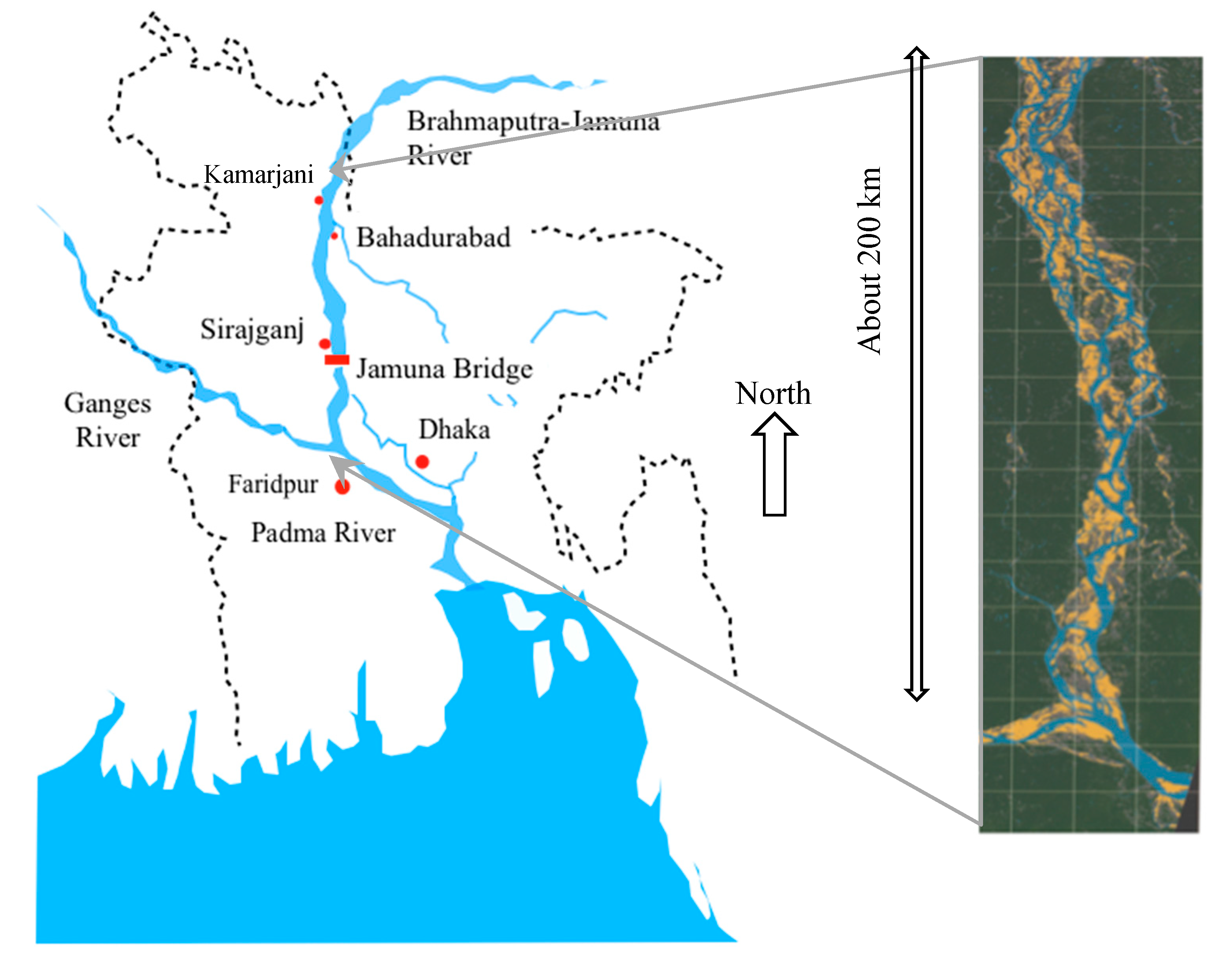
The construction of bank protection works started to save Sirajganj from bank erosion since the 1930s [
5] and the construction of the Jamuna Multipurpose Bridge from 1994 to 1998 [
6], see the map of Bangladesh in
Figure 1. Several so-called hard points such as groynes and revetments were constructed in the period 1980–2010. The main river training structures at the borders of this braiding belt experienced unexpected damage by a series of flow slides. A flow slide is an underwater slope failure because of liquefaction or a breaching process in the subsoil or a combination of both [
7]. This process results in slope and bank failures with successive massive transport of fine sands under water at mild slopes. In this case report a flow slide can include also a combination of a flow slide and a breaching process, because these phenomena occur often combined in the field and are difficult to separate in monitoring data. The following questions will be addressed in this report: did all river training works along that river experience damage by flow slides or other types of geotechnical failures? How did the design of these river training works anticipate possible damages by flow slides? How can the design of river training works be improved to reduce the risk of damage by flow slides?
The size of the bank erosion phenomenon along the Brahmaputra-Jamuna River, the consequences of bank erosion and the role of river training structures, are summarised in
Section 2.
The description of the extent of the damage of river training structures was restricted to some selected cases and it is therefore not a complete overview of all the historical damage, see
Section 3. The analysis of the damage by flow slides and the phenomenon of flow slides is focused on recommendations for the design of river training structures to limit or to prevent damage by flow slides in
Section 4. This analysis used the results of three physical model investigations to study local scour phenomena near river training structures. A field-testing facility is recommended to study small flow slides and methods to prevent flow slides as a step towards recommendations for the design of economic and durable river training structures along the Brahmaputra-Jamuna River in
Section 5.
2. Bank Erosion and River Training Structures
The river training works such as revetments and groynes, along the Brahmaputra-Jamuna River, were designed to stop bank erosion locally [
8] or to stabilise river course with minimum bank erosion [
9]. The severe right bank erosion has occurred with average rates of about 90 m per year [
10] and the center line with 50 m/year [
11] in the period 1960 to 1990. After that period the bank erosion diminishes. The erodible banks consist of most non-cohesive silty fine sand with an average grain diameter D
50 = 0.22 to 0.165 mm and some traces of clay [
3,
4,
8]. The extreme bank erosion exceeds more than 1 km/year along outflanking curved channels on the right bank and the erosion continues during a period of several floods up to abandonment of the outflanking channel often by a cut-off [
8,
12,
13]. The river is braided with meta-stable islands and nodal reaches, mobile sand bars, and shifting anabranches [
8]. Most bank erosion occurs during the monsoon season but some bank erosion is also observed during the dry season [
8,
14]. Bank erosion in an outflanking channel is a function of the near bank flow velocity [
13], a function of relative bend curvature [
15], a function of channel development [
8,
12], extreme flood discharge [
16] and planform changes. Center for Environmental and Geographic Information Services, previously EGIS made yearly predictions of bank erosion at the most endangered locations using empirical models [
12]. The accurate prediction of the channel changes in the region of the Hurasagar junction in the downstream stretch of the Brahmaputra-Jamuna River in 2002 for the next year demonstrated the promising feasibility of these empirical models [
17]. Bank erosion is a complex process and mathematical modelling of the bank erosion process needs further development.
River bank erosion and flooding have disastrous socio-economic effects in Bangladesh. People not only lost their houses and agricultural lands, but also become displaced often permanently and impoverished. Especially in terms of the livelihood vulnerability of riverine island dwellers, strategies to reduce the impact of bank erosion and flooding need to be strengthened [
18,
19]. Riverbank erosion is seen as one of the major causes of national poverty [
18,
20,
21]. In the entire country of Bangladesh, a total of about 729,000 people were displaced by river bank erosion and flooding in the period 1981 to 1993. More than half of them came from erosion-prone areas along the Brahmaputra-Jamuna River [
19,
21]. The structural measures undertaken to mitigate flood and bank erosion had been inadequate and often ineffective according Elahi in 1991 [
18].
The effect of the river training structures in the Brahmaputra-Jamuna River on the bank erosion along the braiding belt was studied by Sarker et al. [
22]. They attempted to separate the natural processes and trends from the effects of the river training structures on the bank erosion process. This analysis did not reach a fair conclusion because the processes determining bank erosion are complicated. The existing river training structures have all deep scour holes and these holes attract a river channel during periods with falling water levels. This might increase the river bank erosion upstream and downstream of a river training structure [
23,
24]. Another complication is the decreasing rate of bank erosion in the Brahmaputra-Jamuna River since the early 1990s. In his PhD thesis [
25], Sarker demonstrated that this decreasing trend is part of the sand wave propagating in that river after the massive earthquakes in Assam on 29 July 1947 and 15 August 1950 [
26,
27]. The low water level at Dibrugarh in Assam rose by 3.4 m after those earth quakes [
27]. This is one of the drivers studied by Sarker et al. [
28] for morphological changes in that river. They developed different process–response models to determine the dynamic morphological changes. Changes in the sediment load might result in changes to the planform of the braided river. These possible changes might require adaptations of existing river training structures in the future.
3. Overview of Implemented Structures: Specifications and Experiences
The selected river training cases are Sirajganj Town protection (
Section 3.1), Brahmaputra Right Embankment (
Section 3.2), Jamuna Multipurpose Bridge (
Section 3.3), Crossbars upstream Sirajganj (
Section 3.4), RCC groynes (
Section 3.5) and Kamarjani Test Structure (
Section 3.6). The similarities in the observed damages of these river training works are described briefly in the following sections.
3.1. Sirajganj Town Protection
Sirajganj town has been threatened by bank erosion and bank caving since about 1930 [
5]. From time to time various stretches of the bank erode and other stretches accrete. Brick mattressing was applied often as a protective measure with temporary success, as the main flow shifted to the opposite bank and resulted in a slowdown of the erosion process. The brick mattresses were damaged and washed away “due to displacement of fine materials from underneath” in 1964 [
5] and 1968 [
29]. As an emergency measure, loose bricks were dumped during the monsoon flood in 1969 and proved to be completely ineffective. These measures were also applied in 1970 [
29] and brick filled wire cages were also dumped along the eroding bank. The extreme roughness of a field of these porcupine cages is effective to reduce the flow velocities. All these measures had limited success and only slowed down the rate of bank retreat.
After all these years of bank erosion, a study for the permanent protection of Sirajganj [
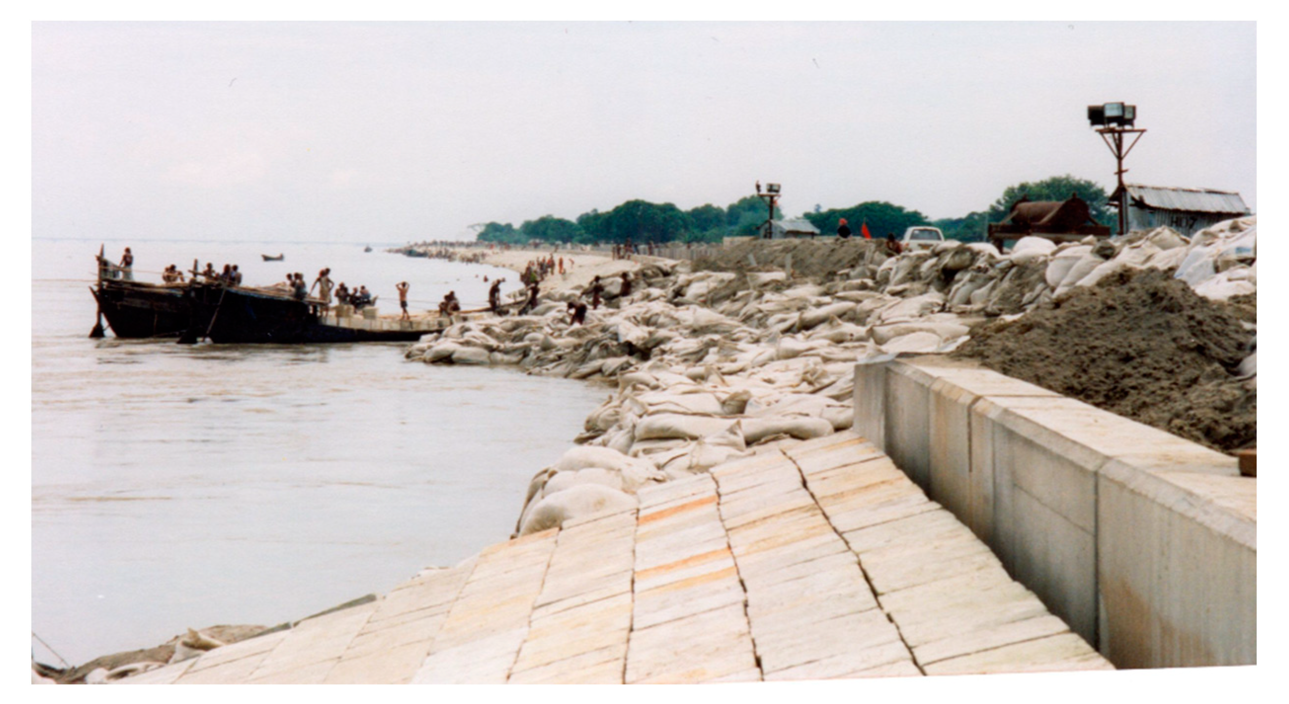
29] resulted in a proposal for a falling apron made from concrete cement blocks and extra surface roughness by steel jackets to reduce the flow velocities along the bank. After independence, Bangladesh experienced a difficult period and that proposal was realised only partly in the period from 1971 to 1974. These protection measures were effective up until the monsoon flood in 1985 when the bank protection of Sirajganj was again severely damaged. When the water levels receded the huge damage to the bank, protection could be inspected. Before the next flood in 1986, emergency works had to be executed to protect Sirajganj. Based on physical model studies, the 854-m-long Ranigram groyne with a hockey head was proposed with a top layer of concrete cement blocks with aggregates made of locally produced bricks (khoa) as a filter on the right bank just upstream of Sirajganj,
Figure 2. Only 820 m of the shank of the groyne with an enlarged end could be completed before the next flood season. However, the flood in 1986 caused new damage to the bank protection.
The existing revetment of the Sirajganj town protection and the new Ranigram groyne was at risk of failure after the devastating monsoon floods in 1988 and 1989. The Sirajganj town protection is part of the more than 200-km-long Brahmaputra Right Flood Embankment.
The project FAP1 [
11,
30] proposed a 2 km new revetment incorporating the existing Ranigram groyne and reclamation of land between the groyne and the town. Sand for this reclamation was dredged from a borrow pit directly in front of the planned revetment in 1996 and the construction work was completed in 1997. According to the design criteria to resist moderate earthquakes, the slope of the revetment was 1V:2H with V = vertical unit and H = horizontal unit, for the upper part and 1V:3H and 1V:3.5H for the lower part. However, this design of the revetment was not made to prevent damage by liquefactions caused by rapid scouring. The design service life of these works has been set at only 30 years for the materials of a revetment (especially the concrete blocks) and 100 years to resist an extreme flow event during a monsoon flood.
The upstream termination of the new revetment had a nose with a small radius which was added to the existing head of the Ranigram groyne. The flow separated at the nose and strong vortices formed a so-called vortex street. That turbulent vortex street caused a deep scour hole. During the construction of the Sirajganj town protection, the damage caused by 16 flow slides had to be repaired in the period from January 1997 to March 1998. Some of these slides formed a series of slides at the same location on the same day. The first slide after the construction of the revetment (14 and 15 August 1998) was triggered in the steep side slope 1V:2H of the local scour hole when the maximum scour depth was approximately at the design level. When this scour hole deepened by several meters, new flow slides were triggered at flatter slopes of about 1V:5H and 1V:6H in the period from 18 to 20 August 1998. In addition, more flow slides flattened the slope of the revetment downstream of the scour hole in September. The changes in the planform indicated an extreme flow attack on the revetment at that time [
17].
The scar due to a flow slide was filled up with geobags, see
Figure 3 as proposed by Prof. D.W. Hight in a report of the project [
31]. A geobag is a box shaped container filled with sand. The material of geobag containers can consist of either an engineered woven or a composite fabric depending on the application requirements.
3.2. Brahmaputra Right Bank Flood Embankment
The main part of the Brahmaputra Right Bank Flood Embankment (BRE) was constructed from Fulchari to Bera with an overall length of about 220 km in the period 1963–1968 [
11,
32]. In many places, this embankment had to be retired, because it had no protecting top layer. The frequency at which the BRE came under attack increased rapidly in the mid-1980s. By far the most significant failure mechanism is the undermining of BRE as a result of riverbank erosion. For the rehabilitation of this long embankment, it was concluded that liquefactions were possible, but not common. Localised slumping of a less serious nature has been observed at three locations up to 1991 [
11].
FAP 1 project executed a systematic geomorphological survey of the right bank of the Brahmaputra-Jamuna River [
11]. In this survey, distinct zones were identified with different predominant material characteristics, ranging from almost pure fine sand to thin strata of relatively cohesive material. However, as all the materials are highly erodible, Halcrow [
11] suggested to consider the bank materials as being effectively uniform concerning resistance to erosion.
The BRE will be reconstructed in the River Bank Improvement Program (RBIP) [
32]. The first phase of this project was carried out to protect the river bank from on-going erosion in 2019.
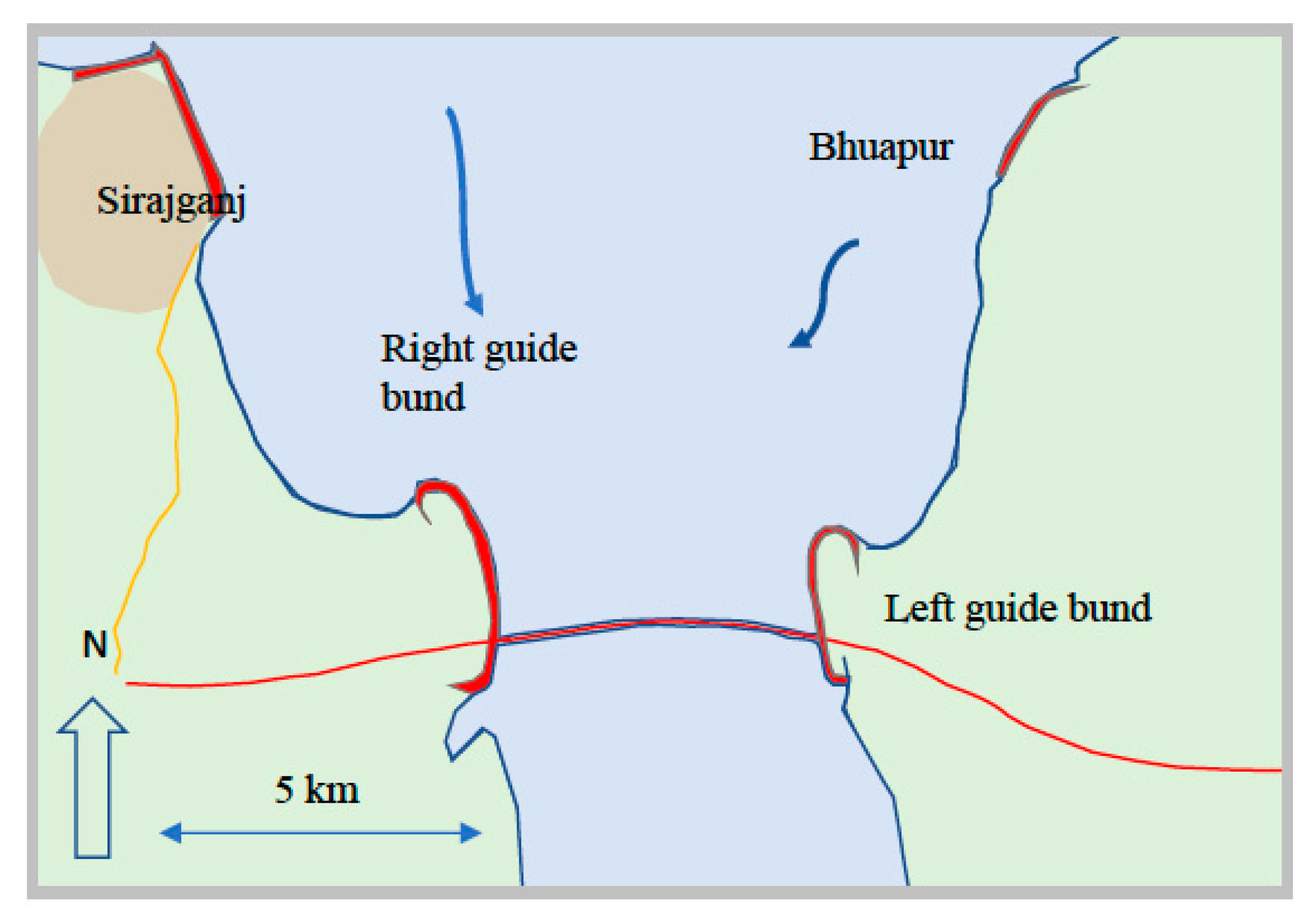
3.3. Guide Bund of the Jamuna Bridge or Bangabandhu Bridge
The Jamuna Multipurpose Bridge (JMB), also called Bangabandu Bridge in Bangladesh, opened in June 1998. This bridge connects Bhuapur on the Brahmaputra-Jamuna River’s east bank to Sirajganj on its west bank. The main part of the river training works comprised of a pair of banana-shaped guide bunds, with a developed length of approximately 3.2 km, one at either side of the 4- to 5-km-wide bridge spanning the river, see
Figure 4. The other parts of the river training works are two hardpoints, one is the upgraded Sirajganj town protection and the other is Bhuapur hardpoint on the east bank. The main function of these guide bunds is to ensure that the approaches to the bridge will be protected against erosion by outflanking river channels.
The design conditions of the guide bunds include an extreme deep river bed as a result of the combination of different types of scour, such as general scour, constriction scour, confluence scour, bend scour and local scour [
33]. The local scour seems to be dominant over all other forms of scour and this is a function of the ‘initial’ depth, that in turn is a function of bend scour and constriction scour [
33]. However, the rapidity of scour during a monsoon flood peak was not considered in the design process.
Geotechnical boundary conditions consist of the effects caused by an earthquake of a prescribed strength, see the seismic zoning indicated on the Bangladesh map published by the ‘Committee of experts on earthquake hazard minimisation’ [
9]. This committee has also published an outline of a code for earthquake-resistant design of structures. The bridge location is in zone II, that means it is designed to resist a basic horizontal force equal to 0.15 of the vertical weight. To guarantee the stability of the guide bunds to resist the effects of an earthquake (mainly liquefaction of the guide bund) the following two measures were considered: to densify the critical zones in the upper 14 m of the subsoil and to apply gentle slopes of 1V: 5H in the upper part of loosely packed sand and 1V:3.5H in the lower, denser part of the protection layer of a guide bund [
33]. The slope steepness has in principle no influence on the occurrence of liquefaction, but the selected gentle slopes reduce the resulting deformation to an estimated maximum 1- to 1.5-m slumping at the top of the guide bund [
34]. The design reports recommend dredging in thin layers to limit the chances of damage by flow slides [
34]. It is also recommended to prepare a code for flow slides and slip cycle failures resistant design of structures, similar as has been done for earthquakes.
The guide bunds were to be constructed by excavating a trench with a depth of about 30 m below original ground level [
6]. The underwater part of the slope had to be covered with fascine mattresses and a layer of rock, a layer of open stone asphalt on geotextile had to be applied at the above-water part. As a result of numerous flow slides during the first months of dredging the two trenches for the guide bunds, it was decided to adjust the design of the protection layer. The soil conditions appeared not to permit the designed slope gradients of the protection layer, 1V:3.5H and 1V:5H. These gradients of the protection layer of the west guide bund were adjusted to 1V:5H and 1V:6H. A review of the performance of the guide bunds [
35] in the period 1997–2009 showed a flow separation at the head of a guide bund as the origin of a strong vortex street causing deep local scouring even deeper than the design scour depth during the monsoon flood in 2006. This deep local scour hole was observed over a length of only 200 m of an upstream section of the western right guide bund, see
Figure 4. The falling apron had slid to a steeper slope than the expected slope 1V:2H.
From 2006 onwards, this protection layer had been damaged locally by downward sliding rock and the formation of a localised hole in the underwater protection [
35]. A detailed study of monitoring data might result in an explanation of the cause for this observed damage in future [
16].
3.4. The Groynes Upstream of Sirajganj
The Sirajganj town protection works were extended with the Salibari groyne, nowadays changed in the nearby Crossbar-1, see
Figure 2. That groyne had initially a T-head and was constructed about 5 km upstream of Sirajganj in 1977. Up to 1986 it functioned well and could reduce the pressure on Sirajganj to some extent. Highly turbulent flow induced by concrete cement blocks in the protection layer tend to draw subsoil sand easily through the coarse matrix of dumped blocks. Pore pressures in the bank during falling stages exacerbate this tendency resulting in rapid slumping of the underlying material and as a consequence, the protecting layer subsides [
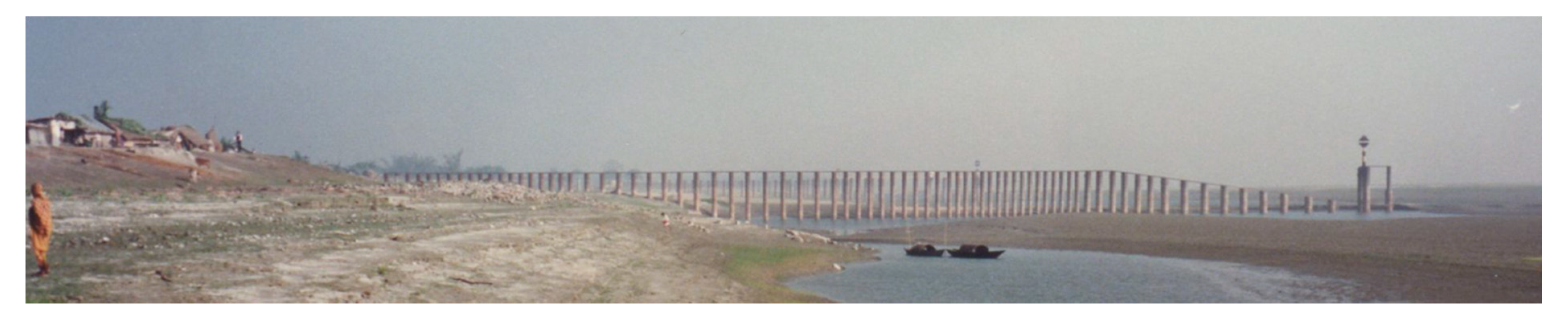
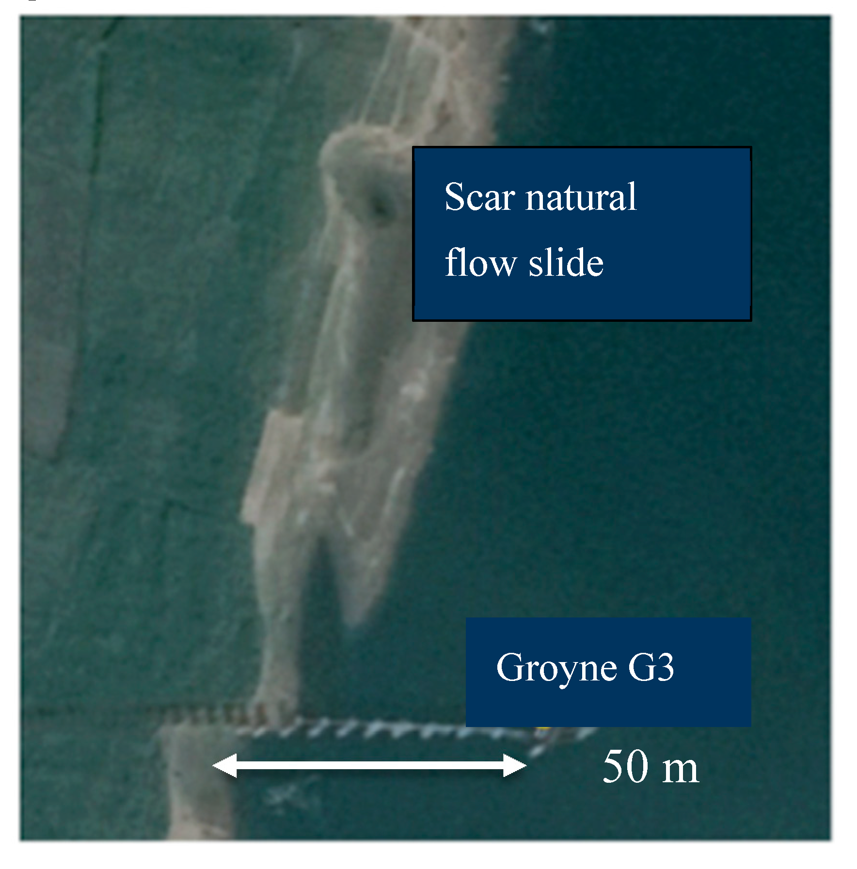
11]. A stretch of 90 m of of Crossbar-3 had been damaged by a flow slide and washed away recently in October 2018 in the English daily Newage available online:
www.newagebd.net (accessed on 17 February 2020). This recent flow slide shows that the problem of damaged river training structures by flow slides in the Brahmaputra-Jamuna River has not been solved during the last 25 years.
3.5. Reinforced Cement Concrete-Groynes
The Bangladesh Water Development Board (BWDB) decided not to implement the technically demanding and expensive FAP1 strategy. As an alternative, the BWDB developed and implemented less expensive so-called RCC-groynes (Reinforced Cement Concrete groyne). In total, 15 groynes of this type had been constructed along the Brahmaputra-Jamuna River up to 2007. The majority of them had experienced extensive damage within a few years after completion of their construction. Rahman et al. [
36] and Zhang et al. [
37] have described in detail the observed damage at two RCC groynes, probably the result of some flow slides. These long groynes were a very new concept of river training works [
38]. It is mentioned that the analysis of this damage has not resulted in successful improvements in the design of RCC-groynes.
3.6. Kamarjani Groyne Test Structure
After a devastating flood in 1988, the World Bank initiated a large Flood Action Plan. A mission with foreign experts recommended a pilot groyne test structure and a pilot revetment test structure on the banks of the Brahmaputra-Jamuna River. These test structures were designed and realised as a Bank Protection Pilot Project, Project 21 of the Flood Action Plan. The objectives of this project were to develop effective solutions for bank protection works against erosion by designing and specifying different types of groynes and revetments using different materials and protective layers verifying its adaptability with regard to local materials and the construction capabilities in the country [
8].
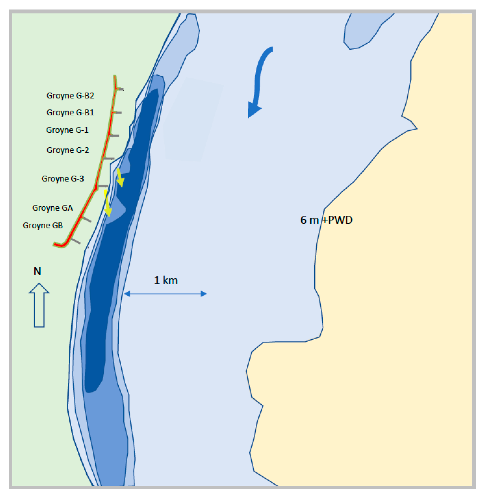
The test structure had been located at the right bank of the Brahmaputra-Jamuna River close to the village Kamarjani. The analysis of samples from borings showed layers of loosely packed sandy subsoil. The test structure was designed at the outer bend of an outflanking channel [
8]. It has an upstream termination made of two short, permeable groynes connected to the embankment, a section with three main, permeable groynes G-1, G-2 and G-3 and a downstream termination also consisting of two short, permeable groynes connected to the embankment, see
Figure 5.
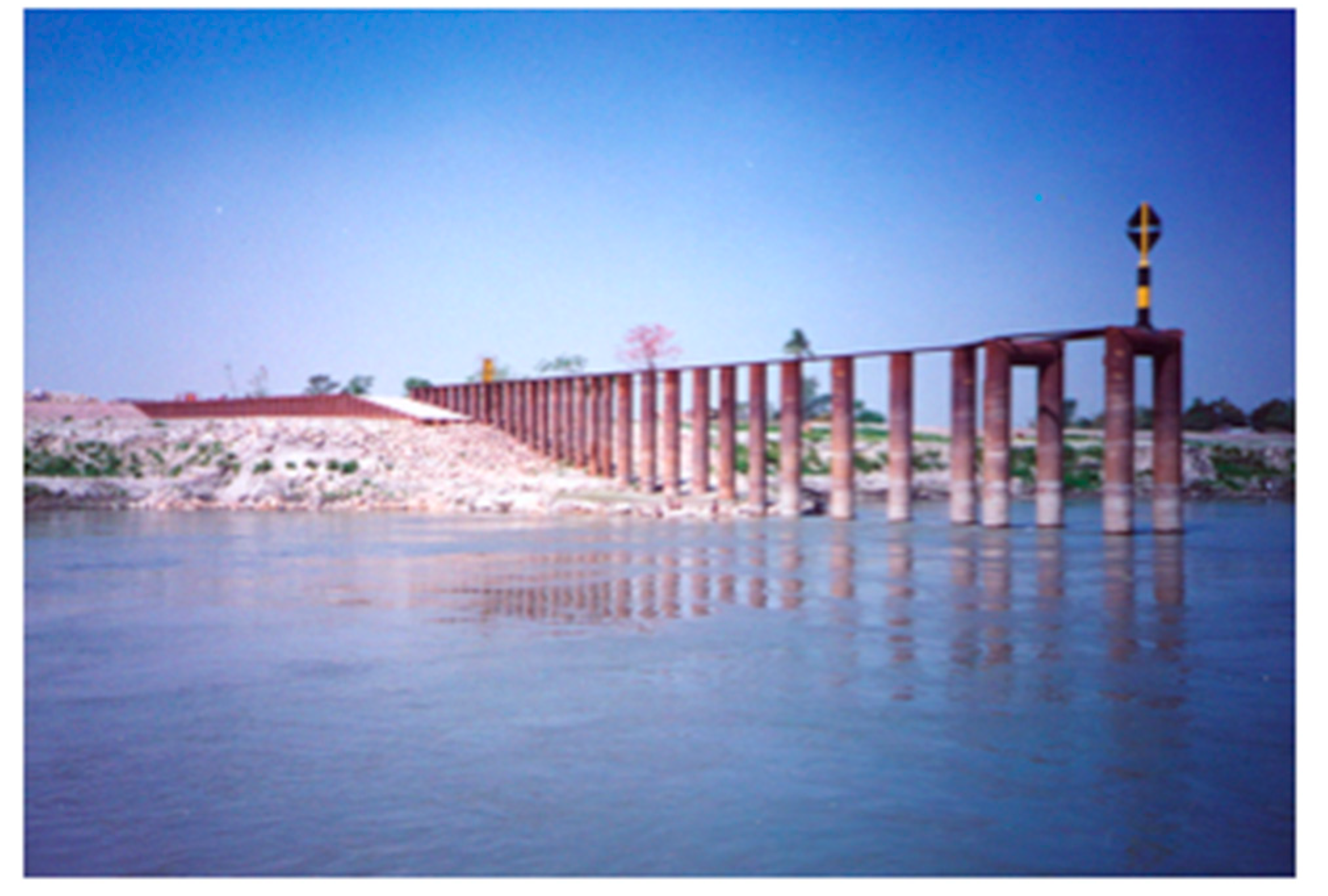
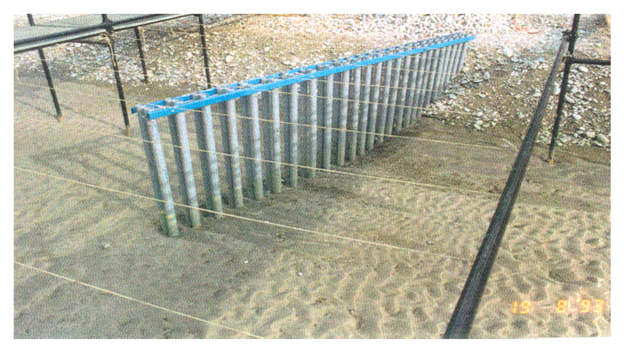
The three main, permeable groynes have tubular steel piles with a diameter ranging from 0.71 to 1.22 m, the permeability ranges in four sections from 80% at the head via adjacent sections 70% and 60% to a section with 50% permeability at the transition to an impermeable shank, see groyne G-1 in
Figure 6. This variation in permeability had been designed to reduce the flow velocities from the head of a groyne to the embankment, the high permeability at the head should contribute to a shallow local scour hole. In the design of the test structure, it was decided to reduce the length of the piles by adding a falling apron and a bed protection around the pile row and the shank.
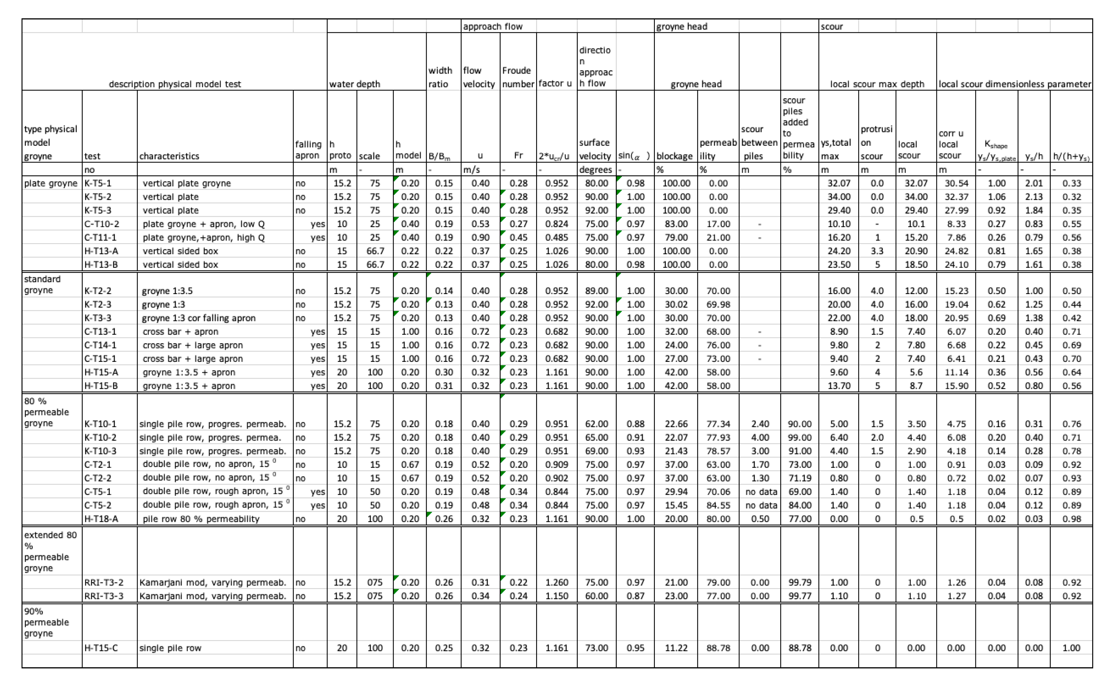
3.6.1. Physical Model Tests
The first tests in a physical model at the River Research Institute in Faridpur, Bangladesh [
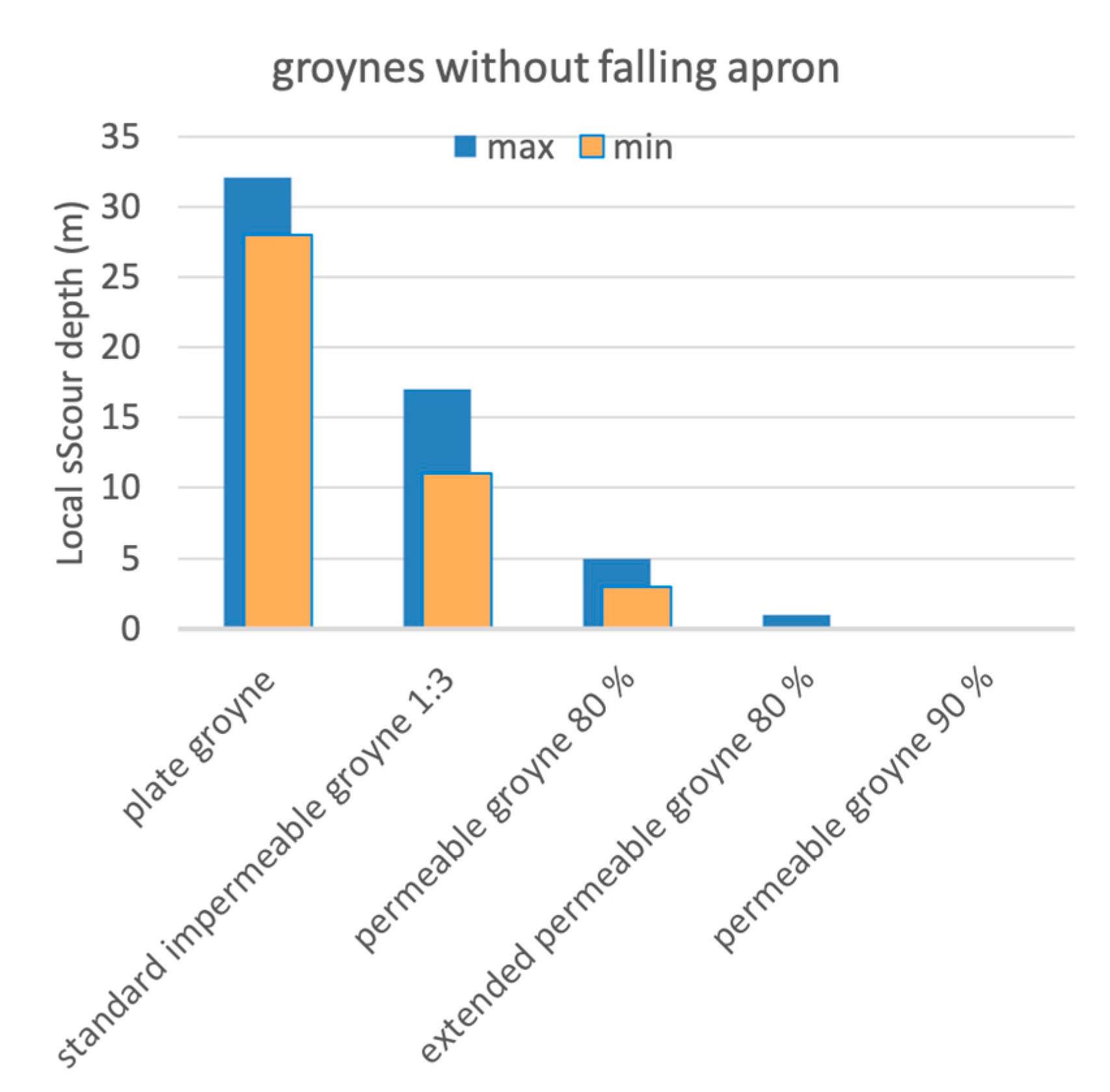
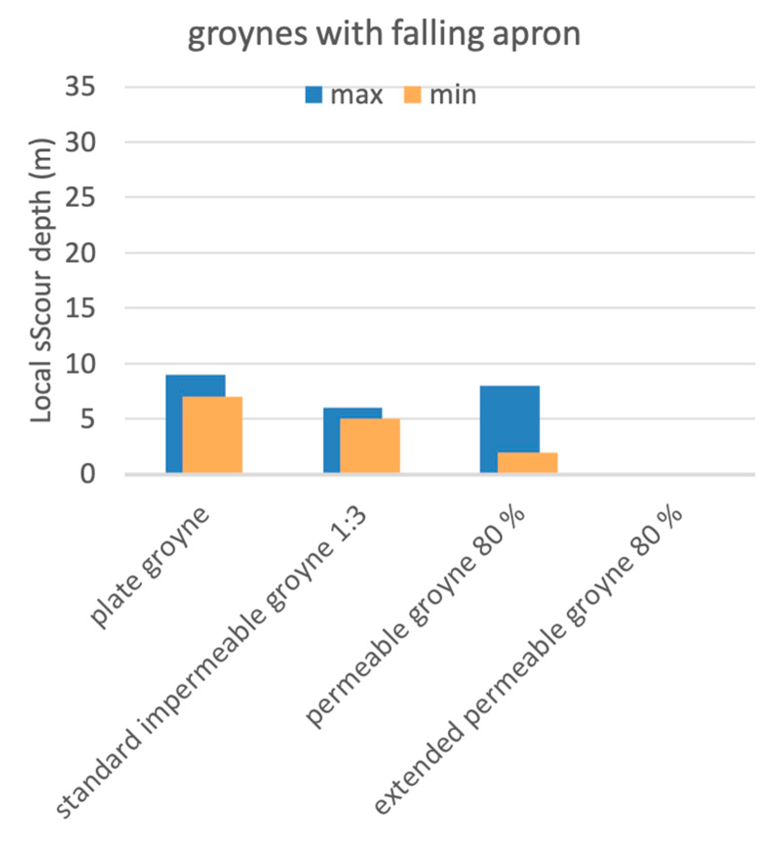
39] showed a very deep scour hole at the toe of a traditional solid groyne with side slopes 1V:3H, the measurements indicated a maximum scour depth more than 15 m below the upstream river bed. The construction of a series of these groynes would be expensive and complicated. That is why permeable groynes were investigated as an alternative groyne type. Physical model tests carried out by River Research Institute [
39] and Compagnie Nationale du Rhone (CNR) [
40] in France showed that the maximum local scour depth varied from 6 to 8 m in the field for permeable groynes with a bed protection and falling apron and 0 to 3 m for permeable groynes without a falling apron and without a bed protection around the pile row, see the summarised scour depths for different types of tested groynes in
Figure 7 tests without falling apron and
Figure 8 groynes with different types falling apron. Two examples of a test with pile row groynes are shown in
Figure 9 and
Figure 10 with almost no local scour and no protrusion scour. More information about protrusion scour can be found in reports of the River Survey Project [
13]. The main data of these tests are presented in the
Appendix A,
Figure A1. It is mentioned that socalled interaction scour in
Figure 10 develops in bends without bank erosion and it does not depend strongly on the type of groyne.
The monitoring of three main groynes in the field measured a maximum local scour depth of 1 to 2 m deeper than the depth predicted by the results of the physical model tests [
41]. The increase in scour depth compared with the physical model tests was probably caused by floating debris consisting of water hyacinths and bamboo trunks piled up at the upstream side of the permeable groynes forming layers of about 1.5 m in thickness and filling a complete groyne field. This floating debris occurs as the flood plain inundates during the rising limb of a flood peak. These field measurements demonstrated the usefulness of physical model testing in the RRI [
39] and in CNR [
40] to optimise the design of permeable groynes to reduce the depth of local scour holes.
The reduction of the high flow velocity (depth-averaged) at the head of the pile row to the flow velocity near the bank is about 50%. The length of a pile row was doubled to about 150 m to obtain a flow velocity reduction of about 75% in front of the embankment sufficient to prevent scour of the bank by the design discharge [
41].
Small local scour holes were measured in tests without a falling apron around a pile row. It meant that the measured scour holes in Kamarjani were caused mainly by the falling aprons (partly fallen) and bed protections around a pile row because they act as a sill for the flow. A permeable groyne with long piles and no bed protection can be effective to prevent a local scour hole. An alternative is a permeable groyne with a bed protection and/or a not-fallen falling apron with a large width.
3.6.2. Field Experiences
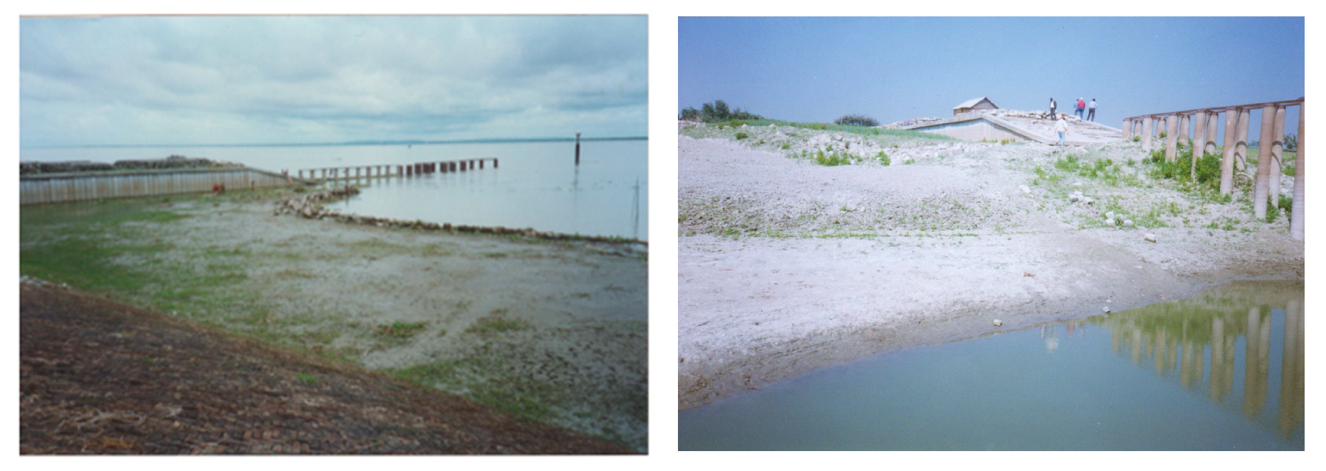
When the water level started to rise at a rate of about 1 m per day, high flow velocities were observed at the transition of the impermeable shank to the pile row of groyne G-2. Three days before the second flood peak on the 20 June, a flow slide occurred at the downstream side of the impermeable groyne head, see the scour hoel in
Figure 11, and a few days later erosion was measured at the toe of the main embankment, see the edge of extensive stone dumping in
Figure 11. The gradual transition of the impermeable groyne head to the pile row was transformed in a sharp transition by a thick layer of floating debris piled up against the groyne. This transition had induced a local flow slide resulting in a scour hole just downstream of the transition and close to the embankment, see the sketch in
Figure 12.
The groyne field upstream of G-2 was filled with floating debris consisting of water hyacinths and banana tree trunks, maximum 300 m
2 and about 1.5-m-thick in the first two weeks of June, with water levels between 20.50 and 21.00 m + PWD [
23]. High flow velocities up to 2.8 m/s did increase the thickness layer of this debris. The maximum depth of the local scour hole increased by 5 m near the tip of the groyne within the 2 weeks before the main flow slide on July 9th, one day before the maximum water level of the third flood peak. The average scour rate of the river bed was 0.35 m/day in that period. That slide eroded about 20,000 m
3 material with a maximum scour depth of 12 m close to the pile row, filled the local scour hole with 12,000 m
3 sediment and finally the maximum scour depth in the local scour hole was reduced to 6 m. The falling apron at the downstream side of the pile row disappeared completely. Extensive stone and sandbag dumping had prevented the impermeable shank from disappearing, see
Figure 12.
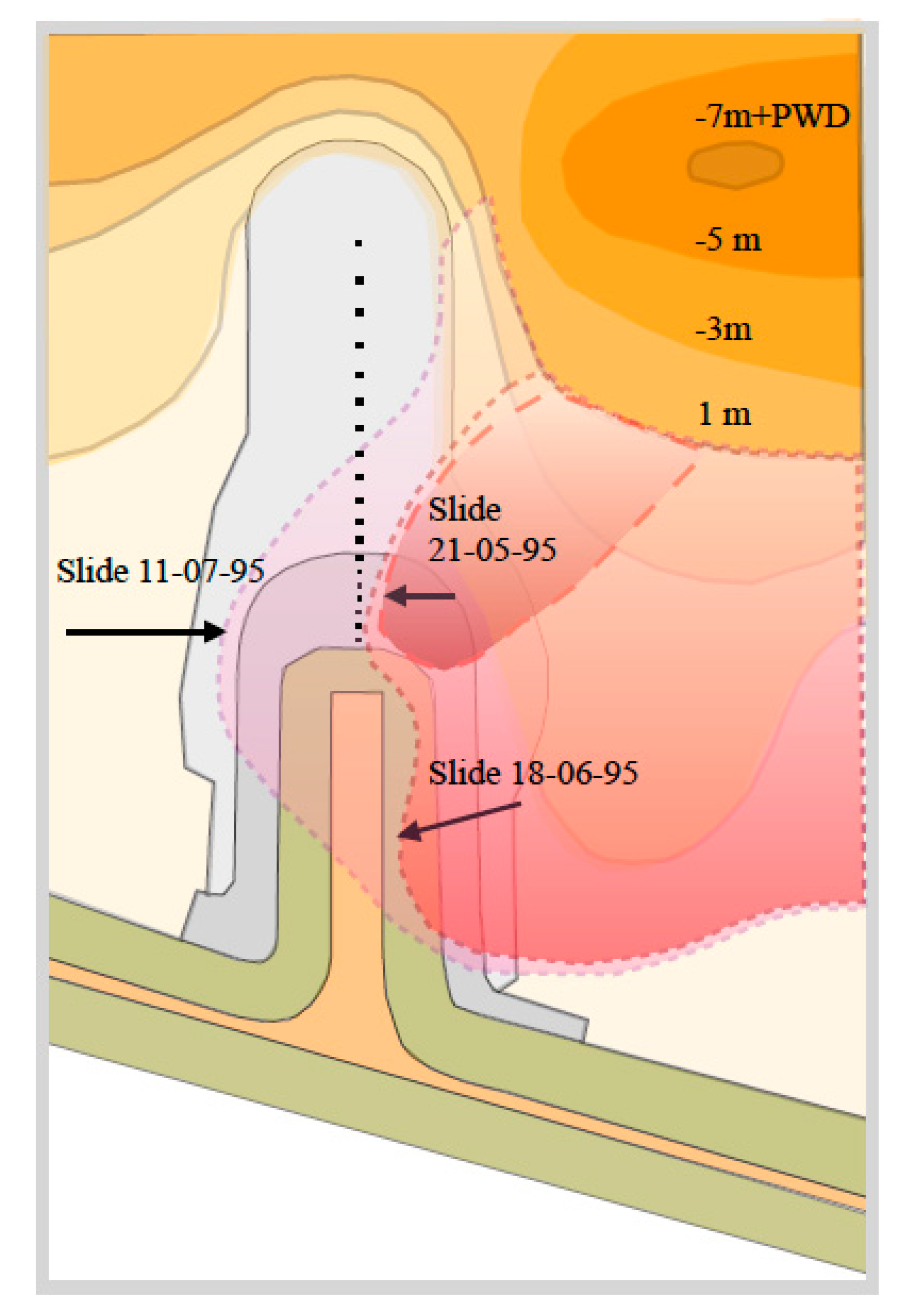
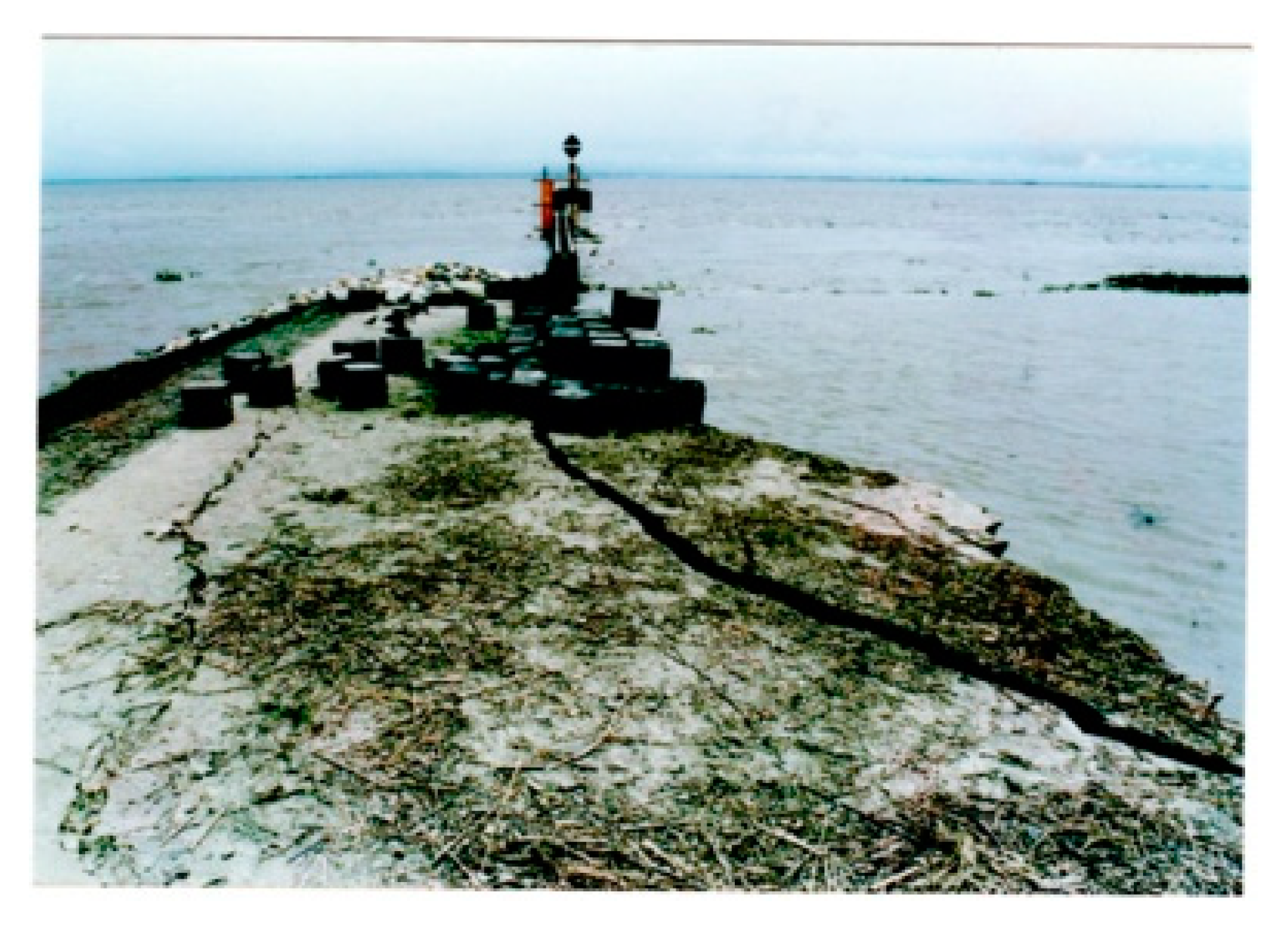
After a quick rise in the water level at a rate of 0.8 m/day for the third peak flow, a main flow slide started at 9 a.m. and stopped in the afternoon. Directly at the start of the slide, a long straight crack parallel to the axis of groyne G-3 was observed at the shank of the groyne. The total volume of about 34,000 m
3 of material had moved in chunks of about a meter thickness. These chunks are part of the natural process, see
Figure 13. The deepening of a local scour hole close to the bank and the transition of the impermeable groyne head to the pile row caused a gradual bank erosion at the rate of 0.5 to 2 m/day.
After an assessment of the damage it was decided to repair the damage as part of adaptation works. These adaptation works include a retired embankment and also the pile rows of groynes G-2 and G-3 were extended and connected to the retired embankment without an impermeable shank, see
Figure 14, [
42]. This extension will accommodate the effect of the interaction between the test structure and the approach channel. In the design process, this interaction was unknown and it became one of the lessons learned from the analysis of the measurements [
23,
24].
After the execution of the adaptation works, the channel silted up and migrated in a downstream direction. With the result that the adapted groynes were not exposed to a strong attack by an outflanking channel after the completion of the adaptation works up to 2018.
Main findings
Permeable groynes made of a row of long tubular piles without bed protection or a falling apron and with an increased permeability from 50% to 80% at the tip of a groyne cause very shallow local scour holes. This design reduces the risk of flow slides to a large extent.
The transition from an earthdam shank to a permeable pile row needs a very gradual transition to prevent a scour hole in case floating debris pile up against the pile row.
A partly fallen apron around a pile row forms an impermeable ridge that causes a local scour hole downstream of the falling apron.
The main failure mechanism is a series of flow slides caused by rapid erosion of the river bed near the head of a permeable groyne. The erosion rate at about 0.3 m/day is caused by a combination of bend scour, a local scour, protrusion scour and the interaction scour between the river channel and the test structure. Secondly, the outflow of pore water might have reduced the stability of the subsoil.
A strong rise of the water level during the rising limb of a flood peak hydrograph indicates an increase in the scour phenomena and as a consequence, the risk of a flow slide augments the following days.
A 1- to 2-m thick layer of floating debris composed of mainly water hyacinths and banana trunks can cause an additional 1- to 2-m pressure scour. This can be prevented by a design of the top level of the steel piles below the level of the floodplain.
The minimum length of a permeable groyne is recommended to be about 150 m (about six times the undisturbed channel depth upstream of a groyne) to reduce the flow velocity at the head of a pile row to below the critical flow velocity near the bank to start bank erosion. This length keeps the local scour hole at some distance from the bank also under unfavourable extreme circumstances
3.7. An Evaluation of the Damage in the Described Cases
The description of the presented cases of bank protection works along the Brahmaputra-Jamuna River (notably Sirajganj town protection, Brahmaputra Right Bank Flood Embankment, Jamuna Bridge, groynes upstream Sirajganj, Reinforced Cement Concrete groynes, and Kamarjani Test structure) showed that the observed erosion processes including bank slumping, flow slides or slip circle failures are common failure mechanisms, not only in the untrained braiding river but also near river training works where they can cause huge damages. These failure mechanisms were often not recognised and not well understood, partly because proper monitoring data were lacking. Only the Jamuna Bridge design adjustments were successful with gentle slopes of the revetments of the two guide bunds constructed in dredged trenches. However, these adjustments are too expensive in the opinion of the BWDB and they prefer more economic solutions to prevent this type of damage. The BWDB tested the Reinforced Cement Concrete groynes as a possible economic solution but all these groynes were severely damaged. The current economic solution are long-guiding revetments, but these are not designed to reduce the risk of damage by flow slides.
It is recommended to start a research program with field tests and river training test structures investigate more economic solutions for river training works with a very low risk of damage by flow slides. This research program should result in effective and economic standard measures to prevent damage from the mentioned phenomena.
4. Flow Slides
4.1. Introduction
Numerous damages by flow slides were described in the previous chapter. The phenomenon of flow slides is explained more in detail in
Section 4.2. Possible measures to prevent flow slides damaging river training structures are treated in the next
Section 4.3.
4.2. Description Phenomenon of Geotechnical Slides
A study of the bedforms in the Brahmaputra-Jamuna River showed ripples with a height of 0.1 to 0.3 m, mega ripples 0.3 to 1.5 m, dunes with a height 1.5 to 8 m and sand waves with a height of 8 to 20 m. This is a classification according to Coleman, [
3]. In one flood, the dynamic changes in these features are impressive. All these bedforms arise from sedimentation and disappear due to erosion by waves, high flow velocities and wind erosion. In the resulting riverbed, no scars can be recognised easily from earlier geotechnical slides. Only recent scars in eroding banks are easy to identify [
3], but not the erosion and sedimentation volumes as a result of a slide in a deeper channel or scour hole. Coleman described slides qualitatively in his pioneering study published already in 1969 [
3] (pp. 163–165). His findings are summarised as follows:
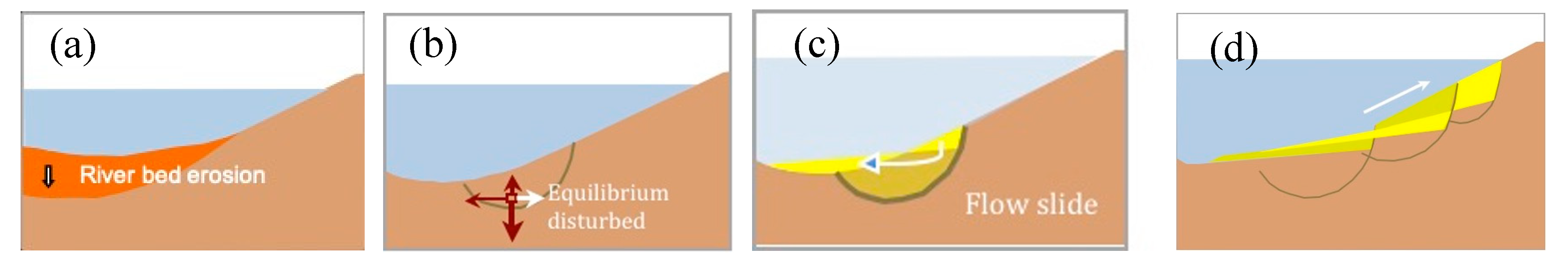
The process of bankline recession can be attributed to two major types of failure, liquefaction and flowage of material and shearing away of bank materials. Flowage failures occur if during a flood a greater water pressure is applied to the sands of the river bed forcing water into the formation. The forcing of water into the formation raises the pore pressure in the strata. As the water level in the river falls rapidly and the pressure against the channel walls is lessened, the water moves from the formation back into the river. This causes a lateral flowage of sand and silt into the channel, resulting in a subaqueous failure and a bowl-shaped scar at the bankline. Above ground water level the overlying natural-levee deposits simply fracture into numerous small blocks and tilt over into the channel.
Slip circle failure occurs as the shear stress along a shear plane surpasses the critical shear stress. Slightly cohesive sediments will shear off along well-defined shear planes. Blocks of slightly cohesive deposits tilted landward by rotation. An eroding bank can retreat by a series of failures. The bank appears as rotated steps from the top of the bank down to the water surface.
Shear failures are extremely common along the Brahmaputra River and the average radius of the scars is 25 to 300 m, see example in Figure 15.
This qualitative description did not result in guidelines for the design of bank protection structures in areas sensitive to flow slides. Varma et al. [
27] mentioned landslides as a problem in some rivers but provided no detailed description or guidelines for this type of failure in Indian rivers. Prof. D.W. Hight of Geotechnical Consulting Group from the United Kingdom explained in detail this phenomenon for the situation at Sirajganj town protection in his contribution to the project report [
31]. He considered a sloped bank that borders a channel in the Brahmaputra-Jamuna River, and this bank comprises fine and very fine sand with some silt with mica flakes (10% to 15% by grain number). When on a volume of this very loose sand a slowly increasing shear force is exerted this volume will contract. The pore water has time to move and the grains keep contact with each other, this is called a drained condition. However, if on the same volume a quickly increasing shear force is exerted, the pore water has no time to move and the grains lose contact with each other. This is called an undrained condition or liquefaction. At the toe of a slope, the weight force of water, subsoil and groundwater is reduced as the river bed erodes during a monsoon flood or by dredging the riverbed, this is called ‘unloading’. The sloped bank exerts a shear force on the subsoil at the toe. The subsoil becomes unstable if the ratio between this shear force and the weight force passes a critical value and the soil starts to move after a trigger, such as a perturbation by scouring or dredging close to the toe of a slope. The magnitude of a perturbation required to serve as a trigger depends on the stress state close to the surface of the slope and its toe.
After a trigger, a large body of subsoil (mainly sand) starts to move. The unstable sliding plane can be determined by a slip circle computation, for example, applying the method of Bishop. All material above the slip circle starts to move under the action of gravity and settles partly in the scour hole or dredged trench and on the bank slope, the remaining very flat slope of the deposits varies from 1V:15H to 1V:30H, see the sketches in
Figure 16. The process of a sequence of instabilities along slip circles is called retrogressive erosion. That erosion process normally takes several hours before the remaining slope is stable again. This temporary stability might be disturbed during a next flood peak flow when a next flow slide might be triggered. A series of flow slides can be observed in the Brahmaputra-Jamuna River within one monsoon flood.
The outflow of pore water after a flood peak can also contribute to a failure, described for example by Coleman [
3] and the BWDB manual [
9]. This phenomenon starts with the inflow of river water into the subsoil by a negative difference in groundwater level and the water level in the river during the rising limb of a flood peak. After a flood peak, the outflow of porewater reduces the stability of the subsoil and liquefaction can result in a flow slide possibly followed by a retrogressive erosion. It is mentioned that in the Kamarjani test site near groyne G-2, groundwater levels in the embankment were measured in pitot tubes at a maximum of 0.5 m above the water level in the river, during the falling limb of a peak flow [
42]. The monitoring period of the water levels in the piezometers was rather short because the piezometers were stolen after the first peak flow. It is recommended to study the contribution of the groundwater pressure to the instability of the subsoil in more detail.
In the design manual prepared by the Jamuna Test Works Consultants [
43], the unloading of the toe of a structure is thought to be caused by a sudden drop in water level instead of scouring of the river bed. On the basis of the described cases in chapter 2 it seems probably that deepening of a scour hole is often a main trigger for a slide in periods with rising water levels.
The Waterways Experiment Station (WES) has been investigating the problem of flow slides which occur frequently in the sandy riverbanks of the Mississippi River in the USA for more than 40 years as described by Torrey III [
44]. These investigations have been focussed mainly on the identification of susceptible bank reaches characterised by the grain diameter of sandy deposits, its density and on the explanation of the failure mechanism. A prediction method has been investigated to assess the potential damage to flood protection levees by flow slides too.
In some estuaries in The Netherlands, about 200 historic flow slides have been recorded in deposits of fine sand during the last century, some of them were very large with a net erosion volume of more than a million cubic meters. The analysis of these flow slides resulted in some criteria valid for the Dutch delta to predict the susceptibility for flow slides [
45]. Near groynes the stability of the upstream slope of a scour hole in loosely packed sand is decisive for potential damage by a flow slide. This stability is likely if the angle of internal friction is less than 30 degrees in the Dutch estuaries. In Kamarjani test site, the angle of internal friction is 27.5 degrees [
8], that might indicate a considerable risk of a flow slide. Two types of the angles of repose can be obtained: the external (or poured) angle of repose and the internal (or drained) angle of repose. For a revetment, the stability of the side slope of a scour hole is decisive for potential damage by a flow slide. This stability is a function of the angle of repose. The critical angle of repose of a subsoil sample is the steepest angle relative to the horizontal plane which a material can be piled without slumping or the surface sand sliding. For loosely packed fine sand the angle of repose is 26 to 28 degrees. Steeper side slopes have a high risk of a flow slide. It is recommended to verify if these Dutch criteria are also valid in the Brahmaputra-Jamuna River.
4.3. Measures to Prevent Damage of River Training Structures by Flow Slides
In a BWDB manual published in 1994 [
9], slides are mentioned but guidelines to prevent them are not included in that manual. The following five types of measures can be considered to reduce or to prevent damage to bank protection structures by geotechnical slides:
4.3.1. Prevention of Deep Scour Holes Close to River Training Structures.
The results of three physical model investigations were analysed to increase the understanding of local scour depths near groynes. These investigations were part of the FAP 1 [
30] and the FAP 21 projects [
8].
The maximum scour depth near an impermeable groyne is the result of different phenomena: local scour due to a vortex street, protrusion scour due to the contraction of flow lines at the upstream side of a groyne and interaction scour caused by the termination of the natural bank erosion process by the river training works. In addition to this, floating debris can cause pressure scour adding to the total scour depth, especially near permeable groynes. Groynes made of a pile row also experience scour around the piles.
Many formulas to calculate the maximum depth, y
s, of a local scour hole near the tip of a groyne are the product of three components: the shape of a groyne head, the narrowing of a channel by a groyne and the flow velocity [
45]:
in which h = water depth, c = constant (-), K
shape = contribution of the shape of a groyne head (-), K
narrowing = contribution from the length of a groyne (-) and F
flow velocity = contribution from the flow velocity (-).
Assuming that the shape coefficient K
shape = 1 for a groyne with a vertical head, called a reference plate groyne with a head slope 1V:0H, that the narrowing B/B
m in which B
m is the width of the channel and B is the length of a groyne, is more or less constant, and the contribution from F
flow velocity is constant, then the ratio between the local scour depth at the tip of a groyne with a head slope 1V:xH and the local scour depth of a reference plate groyne:
This relationship was used in the analysis of the results of these investigations, where B/B
m varied between 0.13 and 0.31 and the influence of the flow velocity was limited by a factor 0.48 to 1.26 to obtain the scour depth related to 2 × u
cr with u
cr = critical flow velocity for the initiation of sediment movement. The main data of the physical model tests are presented in
Appendix A Figure A1. Three types of river training structures are distinguished in the following: impermeable and permeable groynes and revetments.
Impermeable Groynes
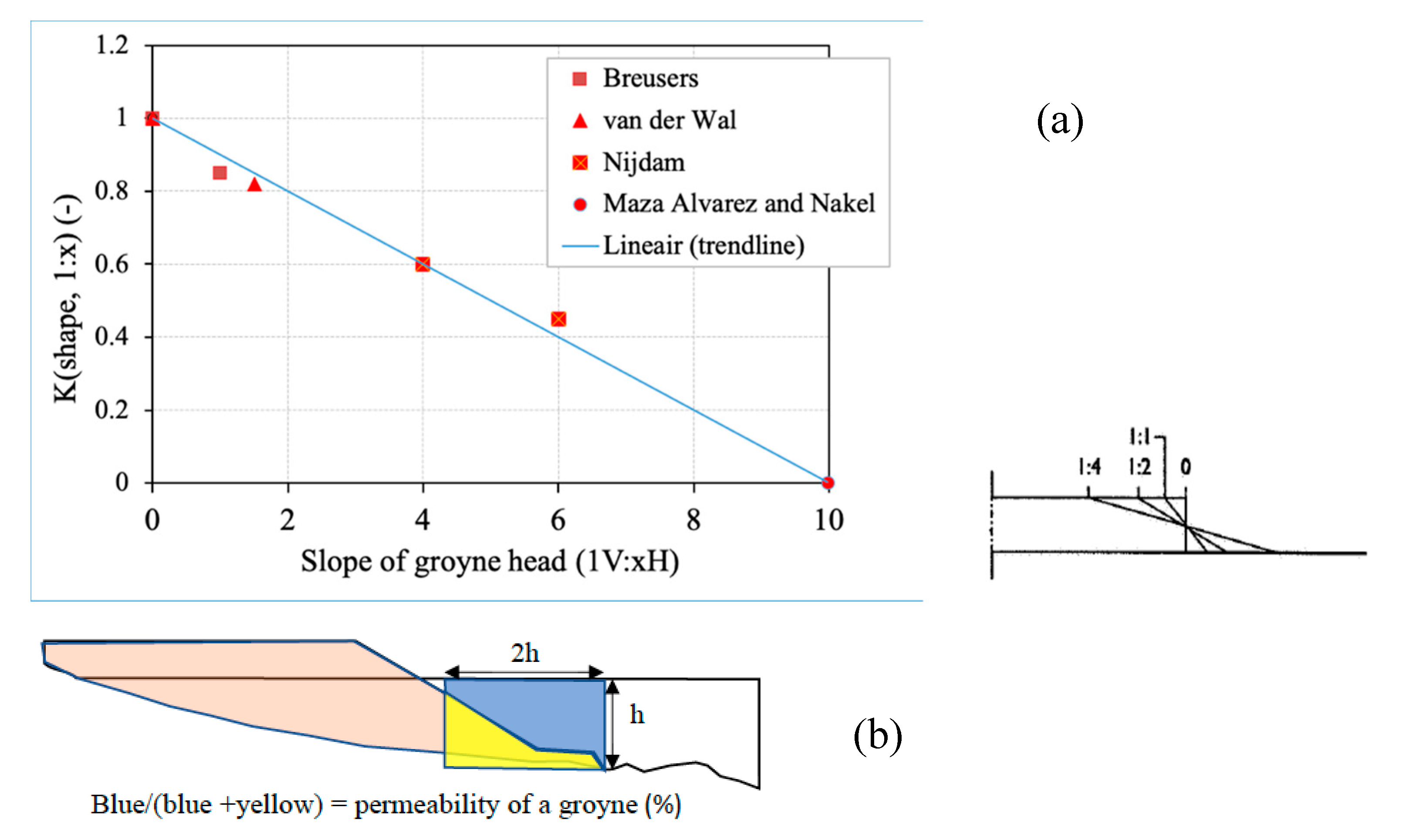
The slope of the head of a standard impermeable groyne has a dominant influence on the size of the local scour hole downstream of this head, see the approximate relationship in
Figure 17 for groynes with a low ratio between the length of a groyne and the width of the channel. Another dominant parameter determining the scour depth is the water depth, but that parameter cannot be changed easily by human action. A groyne head with a slope 1V:10H will cause a very shallow and wide local scour hole and hence a small risk of flow slides, but requires a lot of material. It is recommended to verify this with a pilot groyne in the Brahmaputra-Jamuna River.
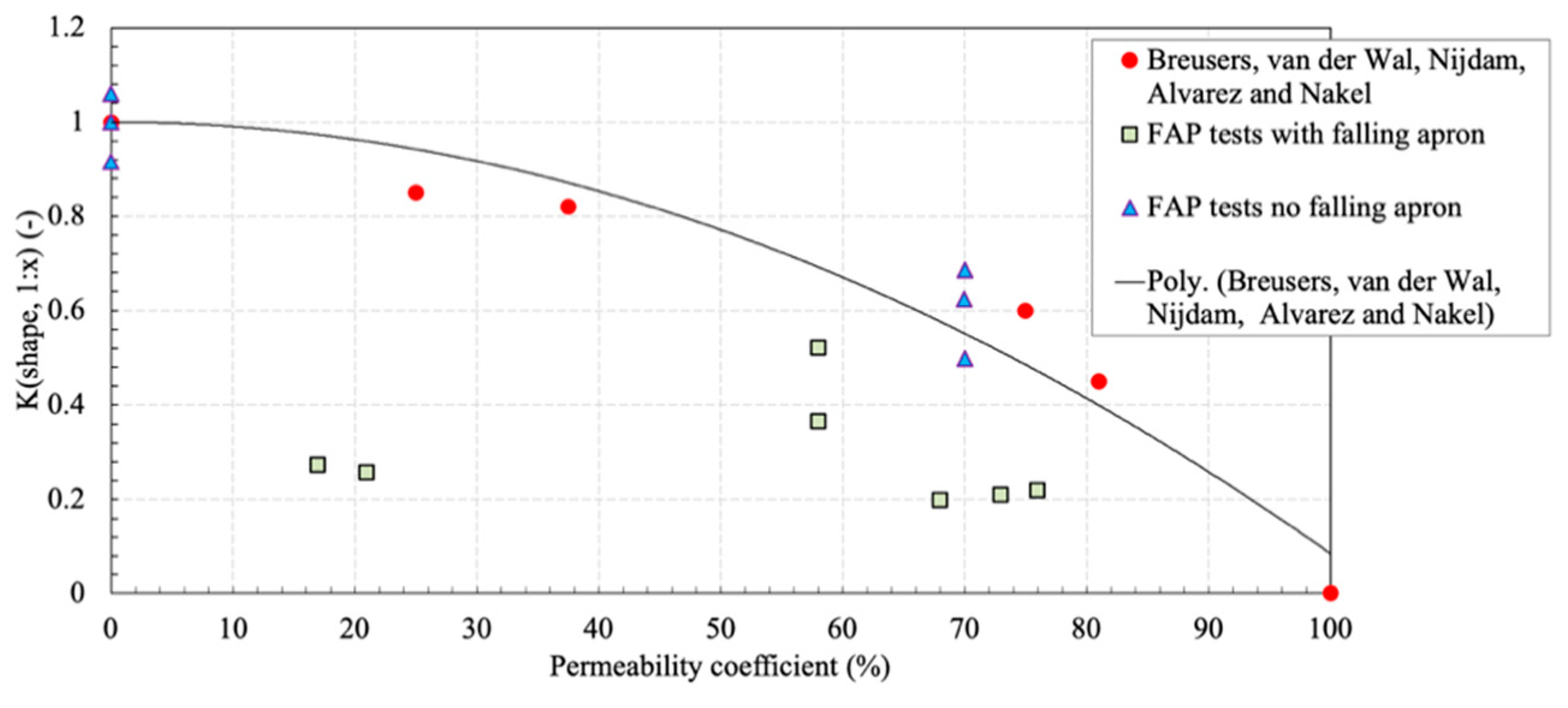
The flow separation curve at the head is the start of a vortex street causing a local scour hole. The location of this type of scour hole depends also on the direction of the approach flow upstream of a groyne. The results of K
shape, 1:x as a function of the permeability coefficient at the head of an impermeable groyne in
Figure 18 show a general tendency that the local scour depth increases as the permeability coefficient decreases and the reduction of the scour depth by a falling apron. The definition of a permeability coefficient c
p is based on the ratio between the flow blocking part of the area with a depth h and a width 2 h starting from the toe of a river training structure and this area in the undisturbed approach flow, according to a personal communication with Hoffmans.
The graph in
Figure 18 shows a reasonable agreement between red marks concerning FAP tests with impermeable groynes without falling aprons and the grey line based on the same data from literature as in
Figure 17 concerning standard impermeable groynes also without a falling apron. The formula of the curve is:
in which c
p = permeability coefficient (%)
A gentle slope of 1V:8H to 1V:10H of the groyne head is recommended to reduce the depth of a local scour hole of an impermeable groyne, also the upstream slope of the shank should be gentle as well. The surface roughness of the slopes should be more or less equal to the roughness of the river bed. The author has observed in several physical models (for example the calibration of the Ganges moveable bed model with the Gorai offtake at RRI) that groynes with these gentle slopes do not attract a river channel as groynes with standard slopes 1V:3H and 1V:4H do. It is recommended to investigate the attraction of channels of a braiding river by groynes.
Permeable Groynes
A measure to limit the scour depth is the application of permeable groynes with a high permeability at the head instead of an impermeable groyne head, using the tendencies in
Figure 18 and formula (1). The results of K
shape as a function of the permeability coefficient at the head of the groyne in
Figure 19 show a general tendency that the local scour depth increases as the permeability coefficient decreases and the scour depth is less with permeable groynes than with impermeable groynes for the same permeability coefficient.
Brown [
46] carried out a physical model investigation to test different types of permeable groynes in the laboratory of the Federal Highway Administration (FHWA), part of the U.S. Department of Transportation. The results show similar tendencies as presented in
Figure 19. The test report was used in the manual [
47] for the design of spur-type streambank stabilisation structures. This manual concludes that if an important design consideration is to minimise the size and the depth of local scour just downstream of a groyne, groyne permeability should be maximised. The results in
Figure 19 holds for groynes with the groyne axis 0 to 15 degrees with a line perpendicular to a bank. The FHWA manual showed also the influence of other groyne angles on the maximum scour depth. Froehlich [
48] proposed a scour formula also with K
shape and K
narrowing for local scour near abutments and although this formula predicts excessive erosion in most field cases, it is part of the software programs of the United States Geological Survey, available online:
https://www.usgs.gov/software/modflow-one-water-hydrologic-flow-model-conjunctive-use-simulation-software-mf-owhm (accessed on 12 September 2020).
Piling up of floating debris can be prevented by limiting the top of the piles to a level below the flood plain. As soon as the flood plain starts to inundate, floating debris appears in the river. Floating debris piled up at the upstream side of a permeable groyne causes extra erosion of the river bed, with about the same size as the thickness of the piled-up layer debris and also an extra pressure force on the pile row of a permeable groyne.
Revetments
An optimised alignment of a revetment is an effective measure to reduce the size of a local scour hole, for example, no sharp bends or noses in an upstream termination of a revetment. Revetments are designed usually with a falling apron, in exceptional cases also with a launching apron. The maximum scour depth is a function of direction approach flow, radius upstream termination in the shape of a guide bund, type, slope and protrusion of a revetment. The direction of the approach flow and the protrusion of a revetment are governed by natural circumstances. However, the slope of a fixed protection layer in a dredged cunet, with gentle side slopes preferably 1V:8H to 1V:10H, is a proven method to reduce local scour. A mild slope is only required in the vicinity of an expected scour hole in an area sensitive to flow slides. The location and the extension of a local scour hole can be estimated from field data or the results from physical scale models.
An extension of bed protection by placing geotextile mattresses at the toe of a revetment also reduces the maximum depth of a scour hole and shifts the location of the maximum depth away from the toe. This approach was mentioned by Torrey III [
44] but rejected because in the Mississippi River delta, there is insufficient space available for revetments with gentle slopes and extended bed protections.
4.3.2. Prevention of Rapid Scouring during a Monsoon Flood
The peaks of a monsoon flood in the Brahmaputra-Jamuna River cannot be influenced economically by human actions so that the water level rises slowly and falls slowly. Instead, a phased construction of a river training structure can be considered to gradually augment the obstruction for the flow and hence a gradual growth of a local scour hole. That will maintain a ‘drained’ subsoil less susceptible to flow slides.
This can be achieved by dividing the construction into several phases over a period of different floods. For example, the construction of sills or several aprons at different levels or stepwise construction of groyne heads. A permeable groyne of two parallel pile rows can be constructed, for example, phased by one pile row the first year and the other pile row the next year. A dredging methodology based on a reduced layer thickness (“ultra-cautious” dredging) will also contribute to maintaining ‘drained’ subsoil conditions.
4.3.3. Dumping of Material as an Emergency Measure
As soon as erosion of the river bed or deepening of a scour hole is monitored close to a river training structure, the river management authority can conclude that the risk of a dangerous flow slide increases and it might be decided to dump material near the river training structure to prevent a flow slide as an emergency measure. Depending on the local situation, a large amount of non-erodable materials and sufficient time are necessary for this measure to become effective. To dump the material precisely in the designed position requires advanced equipment. This emergency measure was often not successful along the banks of the Brahmaputra-Jamuna River in the past.
4.3.4. Improvement of the Subsoil Bearing Capacity
The density of the subsoil increases by vibrating the whole strata with loosely packed fine sand in an area of a planned river training structure. The bearing capacity of the subsoil will be increased after vibrating the subsoil and that action will keep the soil in a ‘drained’ condition. Vibrating the unstable strata is a relatively time-consuming method and it turns out often to be a rather expensive measure.
The construction of the Eastern Scheldt Barrier in The Netherlands is mentioned as an example. Several operations were performed to consolidate the subsoil strata of fine sand and silt in the estuary susceptible to flow slides. A special installation on a large pontoon called Mytilus placed a series of vibration pipes into the bottom, see for more information:
www.deltawerken.com/Deltaworks/TheOosterscheldestormsurgebarrier/schips (accessed on 12 Spetember 2020). After the vibration, the grains of sand were knocked closely to each other down to fifteen meters of depth below the bottom of the estuary. On this subsoil with an increased bearing capacity, three foundation mattresses were placed successfully as a stable foundation for the piers of the barrier.
Another potential measure is a replacement of micaceous fine sand by coarser sand that does not contain mica flakes in the area of the toe of a revetment and the location where alocal scour hole will develop. Dredging companies have experience with liquefaction and breaching phenomena while dredging trenches and filling them. Sometimes they make use of this phenomenon to optimise their dredging operations.
Improvement of the subsoil beaing capacity is often combined with extensive bed protections at the toe of a river training structure made of rock on a filterlayer.
As an emergency action, repair-materials are stored sometimes on top of a river training structure (as a groyne or a revetment). However, this repair material increases the lateral stress at the toe of a river training structure and that will increase the risk of liquefaction at the toe. That is why repair material should be stored at some distance from a river training structure.
4.3.5. Innovative Measures
New developments offer opportunities for innovative measures to strengthen the subsoil to resist high shear forces along slip circles. Another example of an innovative measure is a clay screen in the subsoil to reduce to outflow of pore water. Innovative monitoring systems can offer detailed information on the risk of a flow slide [
49].
It is recommended to follow and to test promising new developments and to build up field experiences in Brahmaputra-Jamuna River with the described measures (prevention of deep scour holes, prevention of rapid scouring, dumping of material, improvement of the subsoil bearing capacity, innovative measures).
5. Conclusions
The phenomenon of flow slides is common in loosely packed sandy deposits in the braiding belt of the Brahmaputra-Jamuna River. Natural flow slides are part of the erosion process of the banks and the islands in the river, but they were not studied in detail. Almost all river training works along that river experienced damage by flow slides or other types of geotechnical failures often followed by a retrogressive erosion or breaching process during the first floods after completion of their construction. These damages required costly repairs and measures had to be taken to prevent more slides. These flow slides were often caused by rapid scouring of the river bed close to a river training structure and in some cases in combination with outflowing pore water. This rapid scouring occurs often together with a rapid rise of the water level as a part of a flood peak.
The design reports concerning river training structures did not contain design rules to prevent damage by flow slides insofar as these reports are available to the author. The repair of training works of the Jamuna Bridge was done by decreasing the slope of the protection layers.
The design of river training works can be optimised to reduce the risk of damage by flow slides or other geotechnical failures. The analysis of three physical model investigations was focussed on the relationship between design parameters of a river training structure and the local scour depth. The following measures can be considered to prevent scouring of a river bed including local scour hole in front of a river training structure built on an unstable, loosely packed sandy subsoil and so minimising the risk of a flow slide:
Permeable groynes
- ○
A series of long permeable pile groynes with a high permeability (at least 80%) at its head and without bed protection or falling apron are expected to create practically no local scour, only some interaction-scour and no bank erosion. In a bend with a large radius this interaction scour will be minimal.
- ○
The top of the piles part of a permeable groyne should be below the flood plain level to prevent a groyne field being filled with floating debris, thereby increasing local scour holes.
Furthermore, the risk on flow slides can be reduced by geo-technical measures, such as vibration of the subsoil near a river training structure, replacement of the subsoil by coarse material and prevention of pore water outflow. Field tests with innovative monitoring systems will improve the understanding of this phenomenom.
A field test program is proposed in the area of the Brahmaputra-Jamuna River to investigate the most economic way to prevent flow slides damaging river training structures. The evaluation of a proposed test program will provide BWDB with the most economic and effective design guidelines to prevent flow slides damaging river training structures.
6. Recommendations
The evaluation of the observed damages of river training structures by geotechnical slides in the Brahmaputra-Jamuna River and the description of the relevant phenomena have resulted in the following recommendations:
It is recommended to analyse the natural flow slides in river banks, on bars and near bank protection structures, to set up a database of geotechnical slides and to prepare a code with a map of areas in Bangladesh sensitive to flow slides. This code might show some similarities to the existing code for seismic zones.
It is recommended to construct and test pilot groynes and a pilot revetment with very gentle slopes and an underwater protection layer with the same gentle slope without falling apron or bed protection. It is expected that these structures will cause almost no local scour and almost no attraction of river channels. This will reduce the risk on flow slides damaging those structures.
If the adapted permeable groynes at the Kamarjani test site will be attacked in future, then a monitoring program is recommended to learn about the development of the river bed in the vicinity of such a test structure.
In a test location in the braiding belt of the Brahmaputra-Jamuna River, small flow slides can be triggered artificially to study flow slides and interventions to prevent them. Such a large-scale test has been executed successfully in an estuary by the Foundation FloodControl IJkdijk in The Netherlands in 2014 [
49]. The potential causes for a flow slide can be studied at a test facility. The knowledge from such field experiences and numerical models will increase the understanding of the following parameters and methods:
The determination of the maximum allowable unloading by local scour so that the subsoil remains ‘drained’ and no flow slides occur. It is expected that this will result in a maximum allowable scour depth, a maximum allowable rate of scour (typically 0.5 to 2 m/day) and a minimum thickness of strata of loosely packed sand required for a flow slide.
The allowable outflow of pore water and the effectiveness of measures to reduce such outflow.
To increase the density of the subsoil, for example, by developing vibration needles on a pontoon or other methods or the replacement of micaneous sand by coarse sand that does not contain mica flakes to increase the bearing capacity of the subsoil.
A next step is to use the field data to validate and to calibrate numerical modelling of the type described by Ham et al. [
7]. A similar model can be tuned to the circumstances in the Brahmaputra-Jamuna River. Its goal is to predict the risk on flow slides near different types of hard points.
It is recommended to verify if the existing Dutch and USA criteria for flow slides are also valid in the Brahmaputra-Jamuna River. In this field test facility, a test program can be executed to develop numerical modelling of flow slides and to investigate economic methods preferably in collaboration with local contractors and foreign experts. Innovative measures can be tested also to verify their applicability in the Brahmaputra-Jamuna River.
This research program should result in effective and economical standard measures to prevent damage from the mentioned phenomena.
