Article

Features and Control of Submerged Horizontal Vortex in Stepped Dissipation Wells

1
Department of Hydraulic Engineering, College of Civil Engineering and Architecture, Zhejiang University, Hangzhou 310058, China
2
Department of Engineering, University of Cambridge, Cambridgeshire CB2 1PZ, UK
3
Zhejiang Province Institute of Architectural Design and Research, Hangzhou 310006, China
*
Author to whom correspondence should be addressed.
Water 2020, 12(8), 2117; https://doi.org/10.3390/w12082117
Submission received: 10 June 2020 / Revised: 22 July 2020 / Accepted: 23 July 2020 / Published: 25 July 2020

Abstract

:
Unlike a horizontal intake vortex, a submerged horizontal vortex is not bounded by a free surface. It has an axial air core submerged in a vessel such as a dissipation well. Due to the motion of its bound point (where the vortex ends), the front wall of the dissipation well could be damaged by cavitation. The goals of this study are to (1) summarize general features underlying the formation and collapsing of horizontal vortices in dissipation wells; (2) identify the features of submerged horizontal vortices; and (3) propose potential measures to mitigate cavitation damage. Through scaling down experiments performed in a transparent dissipation well with two optical sensors, various boundary conditions have been carried out to accomplish this investigation. It was found that a wider inlet flow falling with mixed air can facilitate the generation of submerged horizontal vortices. The optimal mappings between the inlet discharge and the water head differential for maintaining the vortices have been summarized. Depending on different applications, two configurations are proposed to mitigate the adverse effects of submerged horizontal vortices.

1. Introduction

Vortex is a common phenomenon in the world. Examples include tornadoes [1,2], dust devils [3], whirlpools [4] and smoke rings [5]. Under some circumstances, vortices are undesirable due to their destructive effects. Tornadoes and dust devils can cause devastating damage to villages and even cities. Small-scale air vortices also can cause serious problems by drawing small stones from the ground into the engines of a grounded airplane. In addition, inlet air resulting from a water vortex could impair submerged pumps. However, vortices can also be utilized for energy control [6,7,8]. A practical vortex is always a rotational vortex. In contrast with irrotational vortices, rotational vortices can only be maintained by external forces [9,10]. In accordance with the Bernoulli’s principle, the axial core usually stays in the space with relatively lower pressure and higher velocities [11,12].
A great number of studies have been conducted from different perspectives to illustrate the characteristics of vortices in various applications. On one hand, many researchers have focused on the development of strategies to avoid the hazard of vortices in past decades [2,13,14,15,16,17,18,19,20]. On a large scale, tornadoes have been studied experimentally to help improve risk management [1,13]. On a small scale, Lee [21] studied the K-regime in boundary layer transitions and the physical mechanisms of vortex formation at the interface of the soliton-like coherent structures. Ligrani [22] investigated the features of the wavy vortex motions associated with undulating and twisting vortices in a curved channel. For risk management, Das [23] studied the development of tropical cyclone wind fields with the gradient wind model of Holland through calibration and validation against experimental observations. On the other hand, vortices have positive usage in applications. For instance, Hrabovsky [24] experimentally investigated the features of an electric arc, which was stabilized by a water vortex.
Most of the vortices are formed vertically due to gravity. Occasionally, a horizontal vortex can be generated in the dissipation well of a pipeline system. Unlike intake vortices [25], the axial air core of a horizontal vortex ends at a vertical wall rather than the free water surface. Due to the rarity of this phenomenon, submerged horizontal vortices remain poorly understood. This paper aims to understand the general features of submerged horizontal vortices, including the formation, maintaining and collapsing, through experimenting with various configurations. In addition, three dominant sensitive parameters are identified and analyzed, and two configurations are proposed for potential applications.

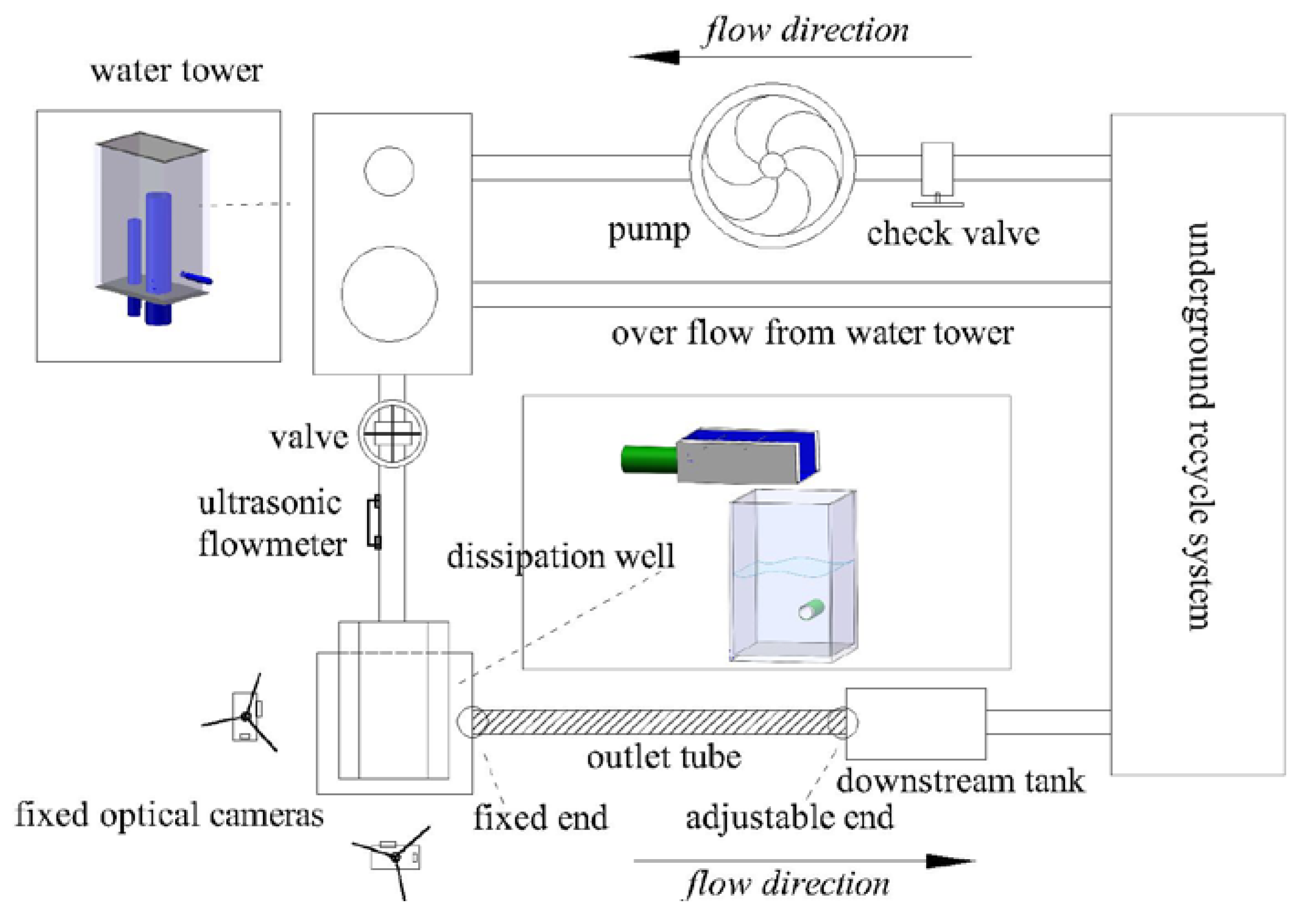
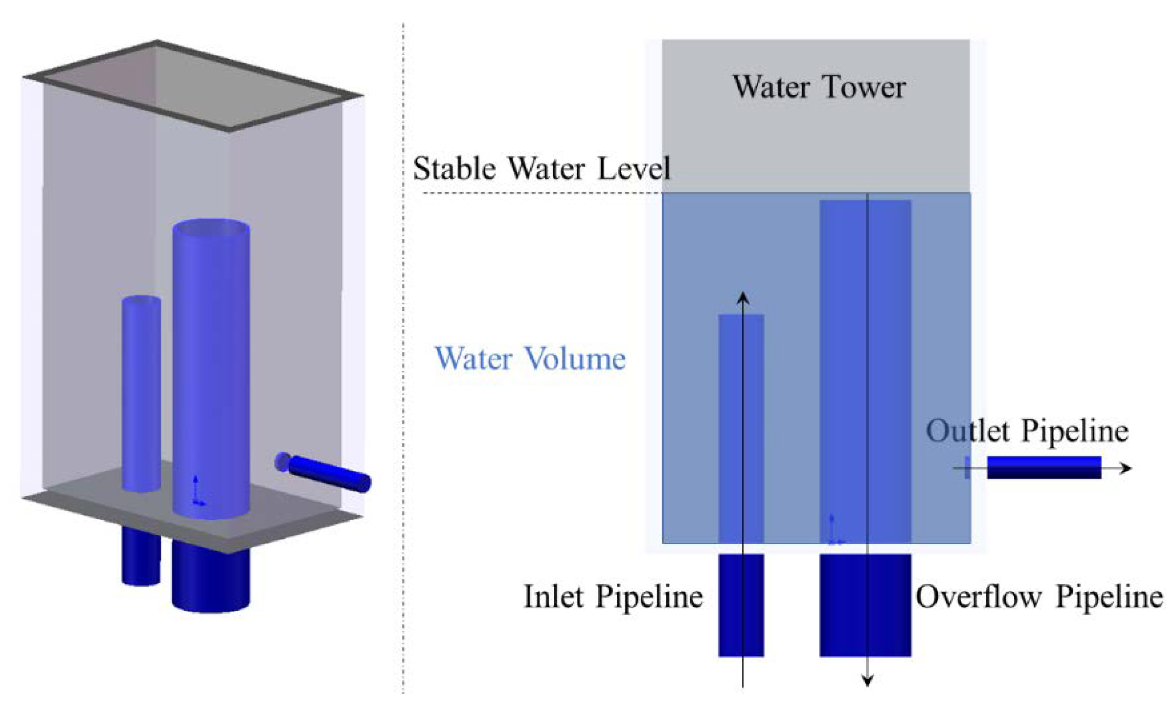
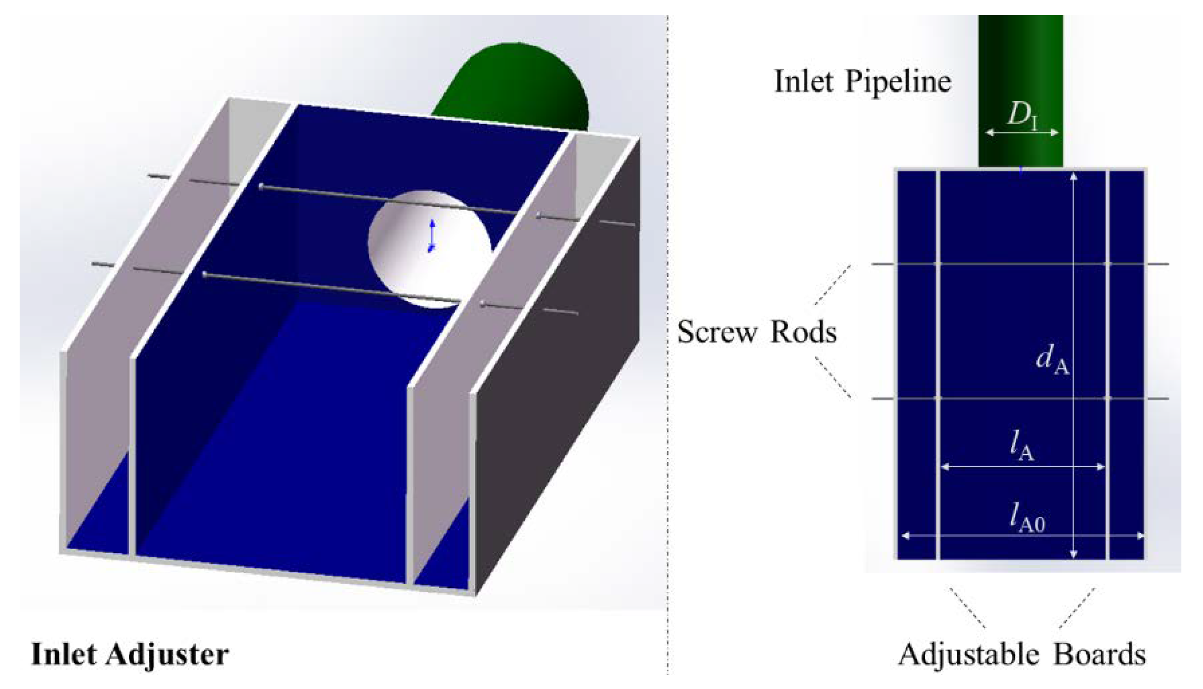
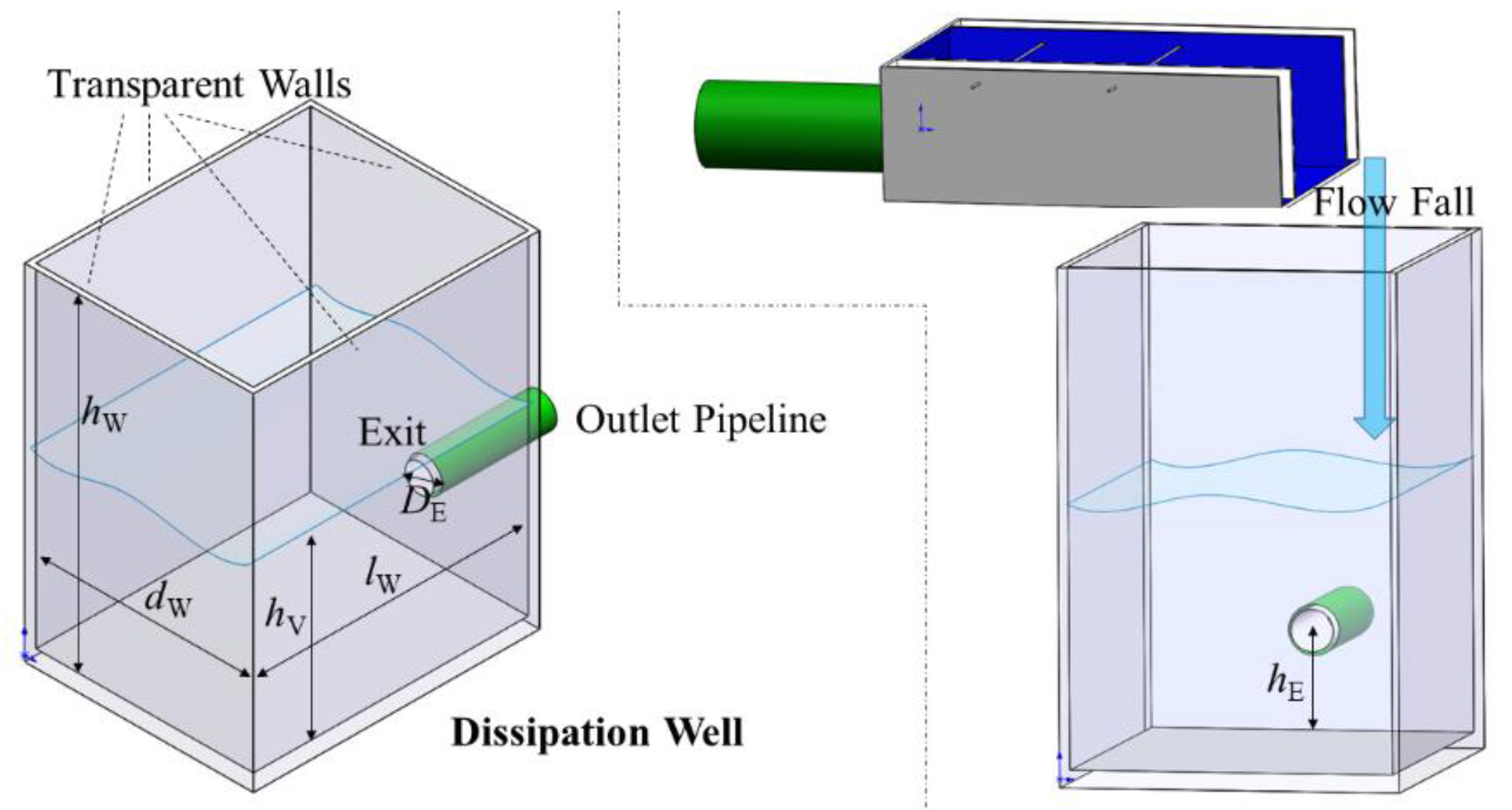
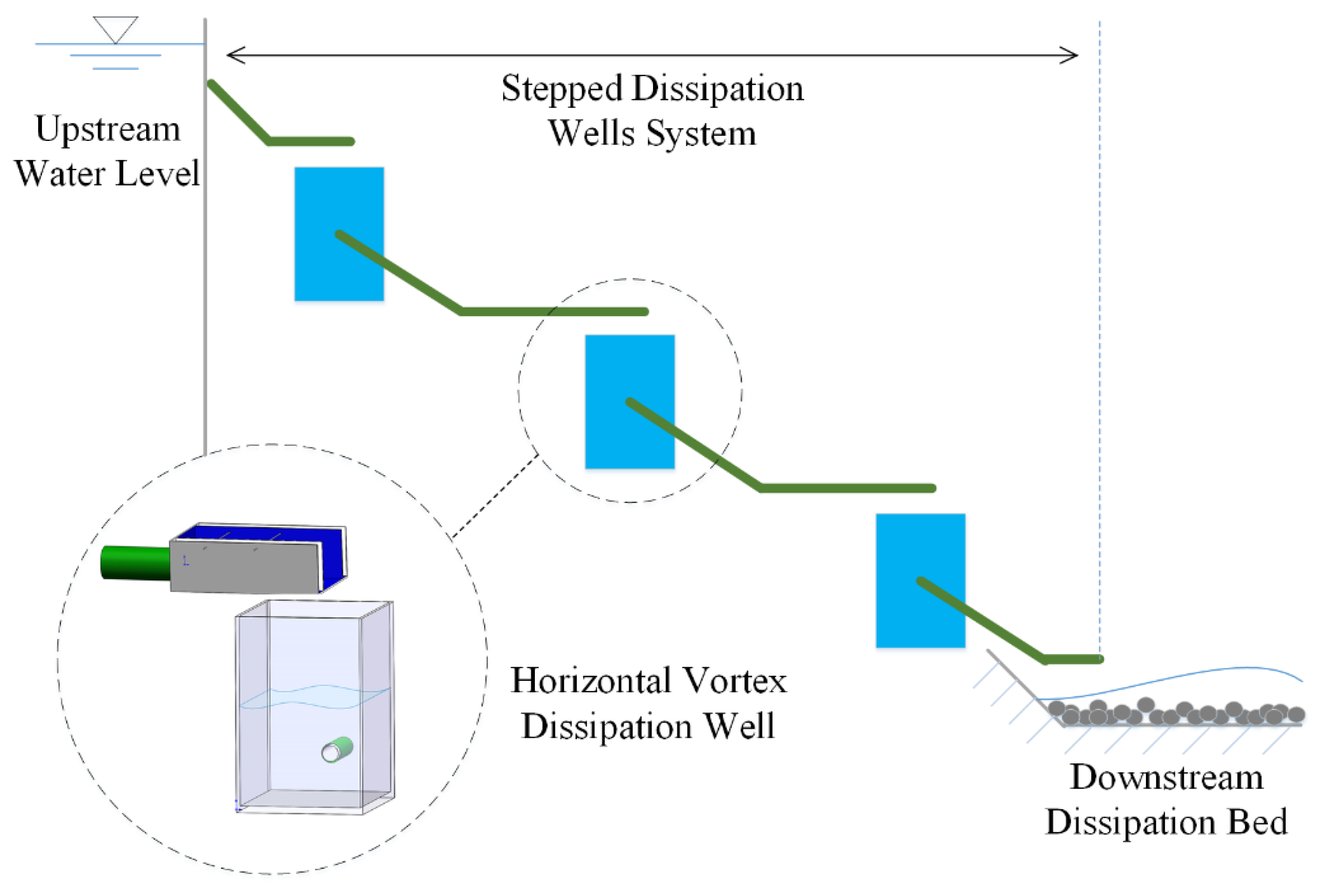
2. Experiment Platform Setup

The whole experiment system consists of three parts: 1. the upstream part, including the upstream inlet pipeline with the water supply devices; 2. the central part, including a discharge control valve, an ultrasonic flowmeter, the inlet adjuster, a dissipation well and some measuring devices; and 3. the downstream outlet pipeline with the recycle system. Figure 1 shows the overall layout of the experiment platform. In this section, the water tower, the inlet adjuster and the dissipation well are particularly explained in 3D models due to their significant roles in the experiment. Other devices include a pump, a check valve, an operating valve, some steel pipelines, two optical sensors, a downstream filtration and recycle system and an underground pool.
As shown in Figure 1, the upstream part includes a pump with a check valve and a water tower. The pump is used to supply continuous discharge from the underground pool to the water tower, while the water tower is used to provide a stable upstream water head. An operating valve is assembled right after the water tower to adjust the flow rate, and, accordingly, an ultrasonic flowmeter is mounted to detect the real-time flow rate. In the central part, there is an inlet adjuster, the shape of which can be changed to generate different flow falling forms. Below the inlet adjuster, there is a dissipation well with a circular exit on its back wall connected to the downstream pipeline. The horizontal vortex occurs within the dissipation well. Two cameras were fixed separately in the front and left sides of the dissipation well to record the dynamic processes. The outlet pipe has a fixed end at the joint of the dissipation well, and an adjustable downstream end to change the outlet altitude. After the central section, the water will be filtrated and recycled into the underground pool. In detail, Figure 2, Figure 3 and Figure 4 show, respectively, the structures of the water tower, the inlet adjuster and the dissipation well.
As shown in Figure 2, the water tower consists of an inlet pipeline, an overflow pipeline and an outlet pipeline. The overflow pipeline is the highest, controlling the water level. To start with, water coming from the inlet pipeline fills the water tower rapidly. When the water level exceeds the top of the overflow pipeline, the extra water volume will be recycled by overflowing. The diameter of the overflow pipeline is designed to be greater than the inlet pipe to make sure the overflow capacity is adequate. In this way, the overflow pipe can be regarded as a circular downflow weir keeping the water level stable.
Figure 3 is a sketch of the inlet adjuster. It is made up of four assembled boards with a circular entrance on its back board connected to the inlet pipe, two screw rods and two inner adjustable boards. The adjustable boards can be moved by screwing to change the width of the flow fall. The width between the two adjustable boards is identified as lA, which is an independent. The width of the adjuster lA0, the diameter of the inlet pipe DI and the length of the adjuster bottom board dA are constant and listed in Table 1.
Liquids fall from the inlet adjuster into the dissipation well, generating a submerged horizontal vortex under some special conditions. Figure 4 shows the detailed definitions of the parameters and the outline of the dissipation well. In the experiment, the dissipation well is made of a top-open plastic box connected to an outlet pipe on its back wall. The material is transparent so that the inside vortex can be visualized. The dominant parameters include the height of the well hW, the height of the water level hV, the width of the well dW, the length of the well lW, the height of the exit hE and the inner diameter of the outlet pipe DE. Among them, hW, dW, lW, hE and DE are constant and listed in Table 1.

3. Experimental Results and Analysis

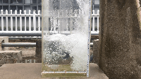
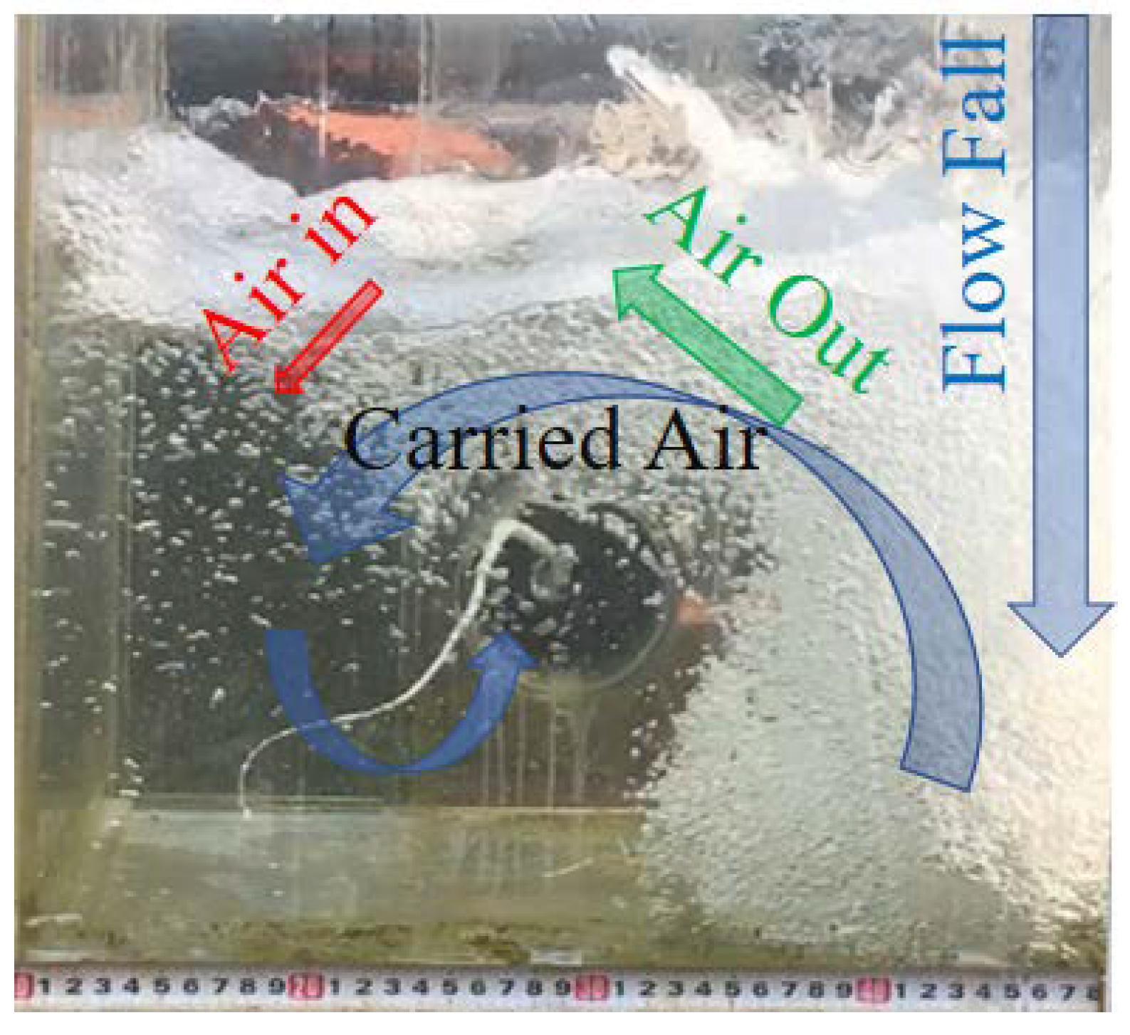
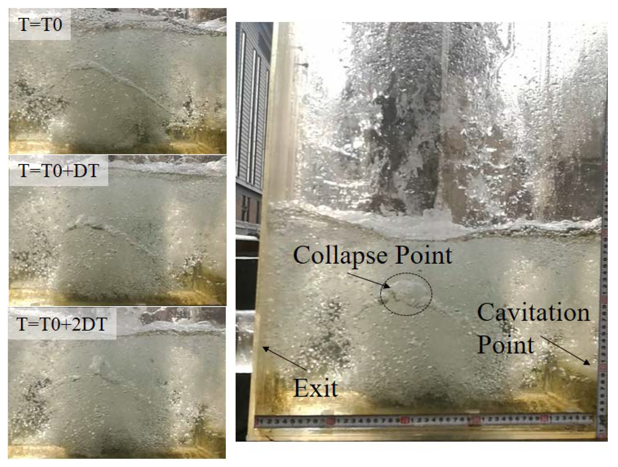
3.1. Formation and Collapse

When the parameters of inlet satisfy the conditions specifically discussed in the following Section 3.2, a horizontal vortex will be generated in the dissipation well. To observe the forming and collapsing processes of horizontal vortices, two optical sensors were installed separately in the front and right side of the dissipation well. The cameras support 30fps and were fixed on two tripods for stable recording. To build a coordinate system, four dividing rulers were stuck on the bottom and right edges of the front and right side walls. In post-analysis, every single frame with a time interval of 1/30 s was extracted from the recorded videos. With the coordinate information, the evolutions of submerged vortices were analyzed quantatively. Figure 5 and Figure 6 respectively show the forming and collapsing processes of a submerged vortex. The axial core is identified to be formed by the trapped air. Compared with the surrounding space, the core has the highest velocity and the lowest pressure according to the Bernoulli’s principle. The inlet liquids and the entrapped air fell into the dissipation well on one side (shown in Figure 5), and subsequently joined a counterclockwise circulation.
Figure 5 is captured from the front camera. The flow fall is mixed fluids containing water and air. After the mixed fluids fell into the dissipation well, they were observed to rebound upwards. Part of the carried air escaped out of the free water surface in this motion, while the other remained trapped within the centripetal velocity field. Along with some newly joint air from vibrations at the free water surface, a vortex occurred from the centre of the back wall exit. The vortex forming process is usually accomplished in a short time. Firstly, the vortex starts to form with some bubbles converging in planes of the front view. Gradually, the converged bubbles in different planes accumulate to connect, from the back side to the front. Eventually, the converged bubbles finish connecting horizontally throughout the well, accomplishing the vortex-forming process.
Figure 6 shows a record of the side camera, where DT = 0.2 s. In a vortex collapsing process, the weakest part of the vortex is usually the highest point of it. As this point firstly loses the constraining of the trapped air, some air volume escapes in forms of bubbles, rising to the free water surface. Soon after, the vortex vanishes as the connection breaks. The collapsing instant is magnified at the right side of Figure 6, where the top of the submerged vortex is losing its stability. Subsequently, in the bottom frame at the left side of Figure 6 (T = T0 + 2DT), the vortex breaks at the middle top, where it is defined as the collapse point. With the disappearence of the vortex, the space near its initial joint point on the front wall is suddenly replaced by water. This momentary change causes an instant and dramatic rise in the endured pressure on the front wall. Hence, the initial joint point is identified as a cavitation point. It should be noticed that the cavitation not only happens when the vortex breaks, but also when the joint point moves. As observed, the joint point on the front wall keeps moving over time, hence the cavitation point actually refers to the joint point in the following sections.

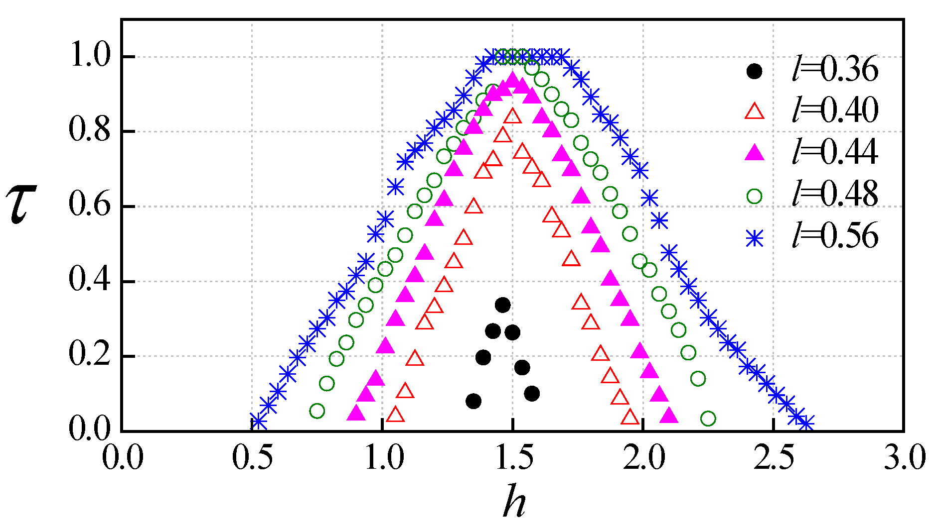
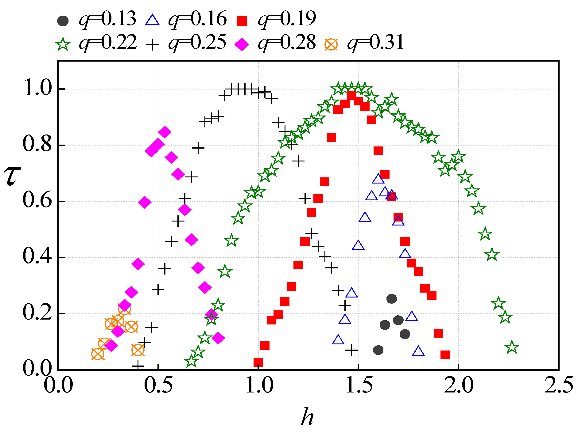
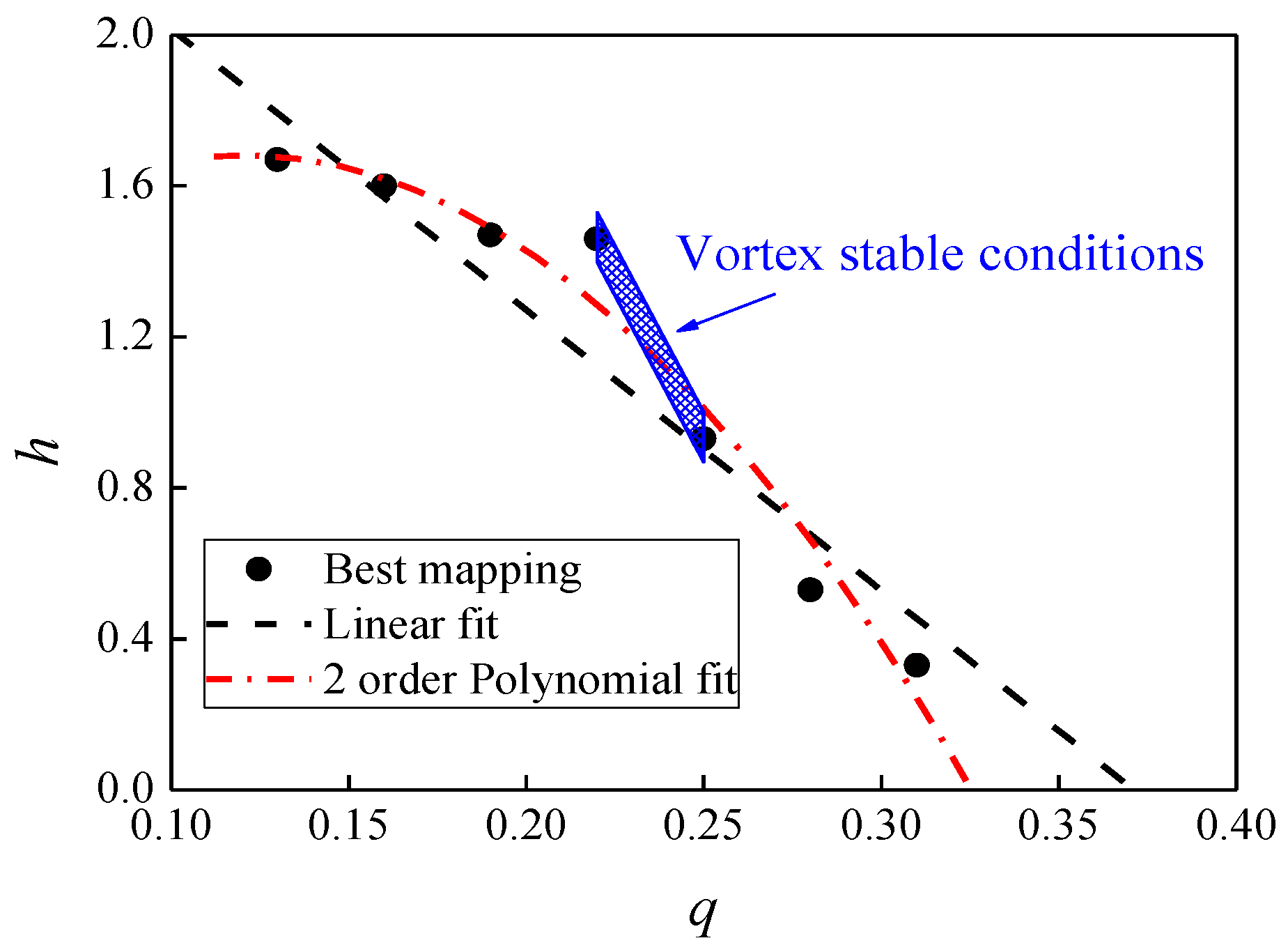
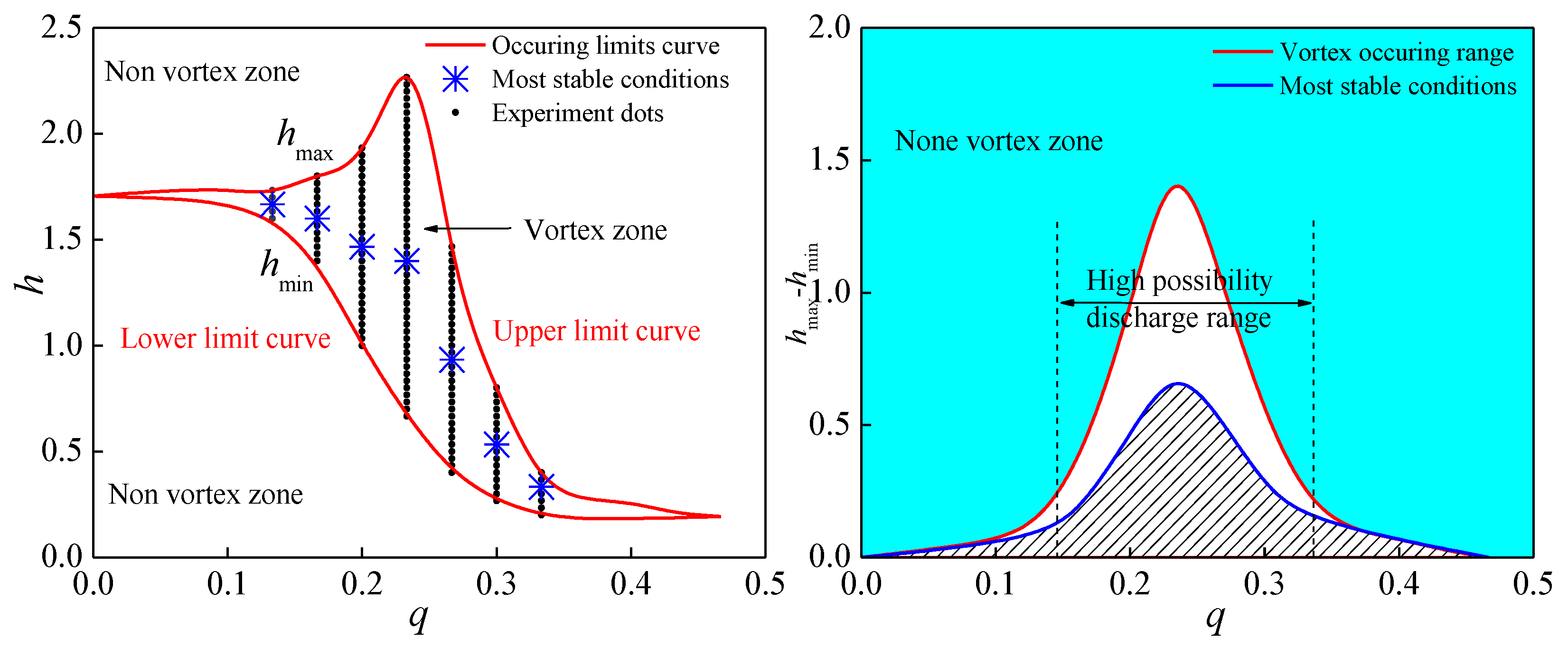
3.2. Formation Requirement Analysis

On the other hand, submerged vortices have feedback effects on the environment. As observed, the vortex accelerates the drainage discharge, leading to a water level drawdown in the dissipation well. Subsequently, the vortex will collapse when the water level exceeds the lower limit to maintain it. Afterwards, as the vortex is not presented, the outlet flow rate decreases to a normal level, leading the water level to grow back. Again, the vortex will reappear when the water level satisfies the forming requirement. For different boundary conditions, the maintaining period of a vortex is different. In the forthcoming sections, some sensitive parameters serving as boundary conditions are analyzed based on information extracted from recorded videos.
It is found that the vortices can only be generated in some certain circumstances, and its stability differs under different boundary conditions. In addition to the inlet discharge Q and the width of the inlet flow fall lA, the hydraulic head differential between the entrance center and the downstream end of the outlet pipeline of the dissipation well is another independent variable identified as Δh. Various conditions were studied changing the three variables. The results are shown in Figure 7, Figure 8 and Figure 9. Note that except Q [L3/T], lA [L] and Δh [L], there are six other important variables in the experiment: tV [T], tR [T], lW [L], dW [L], hW [L] and hE [L], where tV is the vortex maintaining time out of the recorded period tR. lW, dW and hW are constant parameters of the dissipation well, mentioned above in Figure 4. hE is the height of the exit center in the dissipation well. Specifically, tV [T] and tR [T] are the only two variables representing the time evolution, based on which a dimensionless variable τ = t V / t R [T/T = 1] is proposed to reflect the stability of the submerged vortex. As the optimal inlet discharge is supposed to be sensitive to the geometric scale of the dissipation well, another dimensionless factor q = Q∙1s/(lWdWhW) [L3/T × T/L/L/L = 1] is identified to stand for the inlet discharge. In addition to the quantity, lA and lW reflect the performance of the inlet adjuster, effecting the forms of flow fall, hence l = lA/lW [L/L = 1] is considered as another dimensionless boundary condition. On the other hand, h = Δh/hE [L/L = 1] represents the downstream boundary condition, which has a significant influence on outlet discharge.
As shown in Figure 7, keeping q as 0.23, changing h and l, it is found that a greater l is helpful to generate a horizontal vortex. It suggests that a flow fall as wide as the dissipation well should be the best for a horizontal vortex to form. In contrast, the influences of q and h are more complicated. Keeping l as 0.5, more conditions were undertaken under different q and h, shown in Figure 8. Under each discharge, there is always a best h to help horizontal vortices to maintain. Particularly, when q is within 0.22 to 0.25, there are some conditions (1.41 ≤ h ≤ 1.53 when q = 0.22, and 0.87 ≤ h ≤ 0.96 when q = 0.25) in which τ equals 1.0, meaning the vortex never vanishes. The value of the optimal h decreases when q is increased. Figure 9 shows the best mapping strategies of h and q as well as the most stable conditions.
After the least square fit in forms of linear and parabola, two fit lines are shown in Figure 9 to predict the best mapping relation between q and h, which can be expressed as follows:
Linear fit: h = 2.76 − 7.44q
Second order polynomial fit: h = −40.2q2 + 9.7q + 1.1
in which the standard deviations s = i = 1 N ( h i f h i ) 2 N are respectively 0.161 and 0.095, where N is the number of samples, i is the series number and h i f is the fitted value of h i . The blue zone in the figure represents the requirements of the most stable conditions concluded in the experiment. Equation (2) agrees better on these stable conditions. However, it has to be clarified that this empirical equation only fits the conditions when l = 0.5, thus the optimized mapping may differ as the falling form changes.

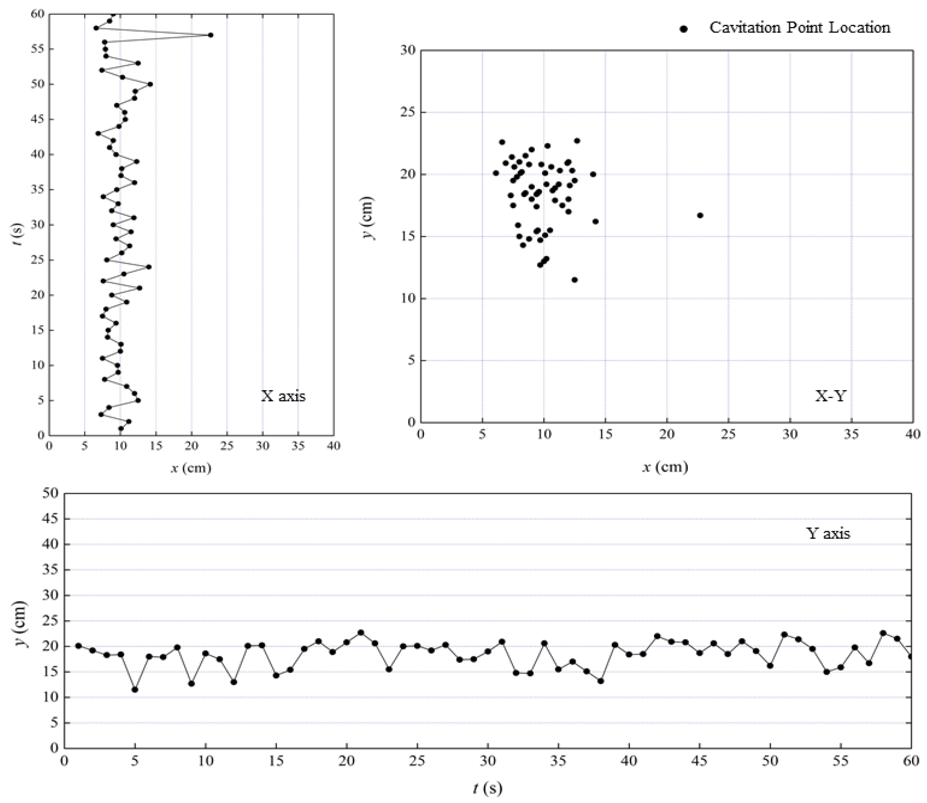
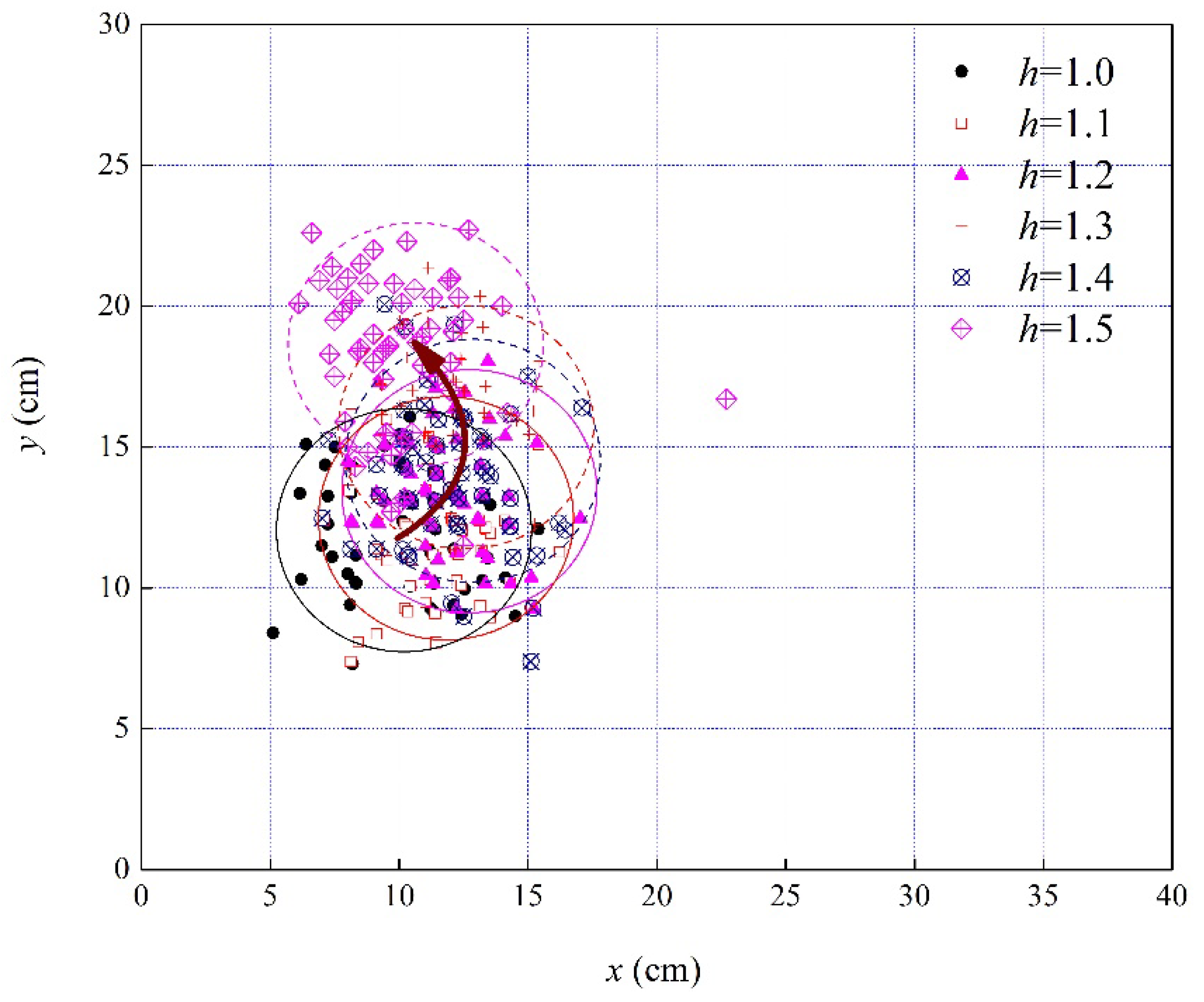
3.3. The Motion of Cavitation Point

On one hand, the horizontal vortex can help enhance the energy loss by additional friction between the liquid and air. On the other hand, it may also cause damage to the front wall because of cavitation. Hence, it is ideal to have a stable horizontal vortex with a greater diameter and a motionless joint point.
Take a certain circumstance, for instance, when l is 0.5, q is 0.22 and h is 1.5. Extracting a frame per second in a one-minute video helps to track the cavitation point movement, shown in Figure 10. Despite it being one of the most stable conditions for a horizontal vortex to maintain, the cavitation point is not static over time. The best thing to do is to search for an optimized operation strategy that can fix the joint point. Another possible solution is to open another outlet exit on the front wall containing the moving area of the cavitation point, which still needs to be validated in further experiments since the discharge and pressure field will be changed as well.
To find the effect of h on the cavitation point moving area, six cases of different h from 1.0 to 1.5 (keeping other variables unchanged) are plotted in Figure 11. For each case, 60 pictures are extracted respectively every per second to describe the cavitation ranges. It is found that with the increase in h, the center of the cavitation range slightly moves upwards. However, the size of the cavitation area does not change much, which indicates that h has little influence on the size of the harmed area.

4. Discussion

The submerged horizontal vortex is a rare phenomenon compared with the vertical vortex, as it occurs only under specific conditions. In this study, the conditions forming a submerged horizontal vortex and its general features were investigated by analysis of the flow patterns in the dissipation well. The effects and sensitivity of three non-dimensional independents h, l and q were studied. In addition, several generic rules were identified with various case studies. In general, a greater l is helpful to generate a horizontal vortex. In terms of h and q, there is always a best mapping relationship between them under different l. To be noticed, the shape and dimensions of the dissipation well remained unchanged throughout this study. Besides, it should be better analyzed if more pressure and velocity data could be obtained within the dissipation well. However, the installation of additional sensors within the dissipation well may disturb the flow field. Therefore, in this study, only an optical measurement was carried out. In further investigations, information of pressure and velocity distribution will be tested if possible.
For practical applications, in order to decrease the scouring on the downstream basin due to the huge hydraulic head difference [26,27,28], a stepped horizontal vortex dissipation wells system is proposed, as shown in Figure 12. In addition to generating electrics, sometimes in flood seasons the reservoirs need to release water through spillways or tunnel spillways in order to keep the water level under the security line. Normally, a spillway should be clear and smooth enough, usually equipped with a flip bucket at the end for dissipating kinetic energy. Tunnel spillways are constructed inside rock masses, while the entrance can be set submerged, sometimes even at the bottom of reservoirs. It is designed to allow more flexible operations to control the flow rate rather than entirely depending on the live water level. On the other hand, the tunnel spillway usually has less frictional head loss as the air–water friction is usually much greater than the pipe–water friction. The proposed stepped dissipation wells system basically requires several places suitable to construct dissipation wells. Owing to the effective energy-dissipating ability of vortices [28,29,30], the proposed system is supposed to protect the downstream basin by dramatically decreasing the impact on it. In such systems, the great hydraulic head differential can be divided into several sections to disperse the impact. Every section will generate a submerged horizontal vortex inside the well, dissipating in the following outlet pipe, in this way to help to decrease the kinetic energy transformed from the gravitational potential energy. Figure 12 is the layout of a stepped horizontal vortex dissipation wells system.
On the other hand, in long stepped pipeline systems, the entrapped air is undesirable because the two-phase flow is likely to be harmful including local air retention and cavitation [31]. In these situations, the stepped wells can help release the entrapped air and reduce the intensity of the water hammer by cutting long pressured pipelines apart [32,33,34,35,36,37,38,39]. These strategies have to be studied with the goal of preventing submerged horizontal vortices [40]. Based on the experiment in our study, Figure 13 shows the preventing strategies of stepped dissipation wells. In the left half part, the range which the two red curves formed represents the conditions that can generate submerged horizontal vortices. The red curves are the critical conditions, while the blue marks represent the best environment for a vortex to maintain. Subtracting the two red critical curves, a possibility distribution under different discharges is shown as the right half part in Figure 13, where the red curve stands for the vortex occurring possibility, while the blue curve is the most stable conditions. When the non-dimensional discharge q is equal to 0.23, the submerged horizontal vortex reaches the widest generating range on h, figuring 1.42 of hmax-hmin. To avoid the harms brought with submerged vortices, this analysis suggests engineers to keep q under 0.1 or greater than 0.4, where only strictly limited possibilities remain to generate a submerged horizontal vortex.
In the further study, we will conduct further investigations on the sensitivity analysis of the boundary conditions including the flow falling forms and the inlet geometry. The feasibility of the double-exits dissipation wells, which have two exits set separately on the opposite walls to avoid cavitation, will be validated through experiments. Furthermore, the strategies to form a stable submerged horizontal vortex with a greater axial core diameter and static joint point will be studied.

5. Conclusions

In this study, submerged horizontal vortices generated by vertical flow fall in a dissipation well are systematically investigated. They are formed by the counterclockwise circulation flow field in the well and the axial air core is formed by the trapped air in the liquid. Based on the observations and data analysis, three main variables affecting the formation of submerged horizontal vortices were identified. The width of the inlet flow fall has a positive correlation with the occurrence possibility of submerged horizontal vortices. The head differential between the exit and the downstream end, as well as the inlet discharge, have a parabolic relation with the occurrence possibility. The submerged horizontal vortices provide an additional dissipating effect in stepped dissipation systems. On the other hand, due to the instability of vortices, there is the harm of cavitation on the front wall of dissipation wells. To prevent this phenomenon, the dimensionless discharge should be kept out of the high-possibility range, which is 0.14–0.33.

Author Contributions

Data curation, M.S. and L.Y.; investigation, B.Z.; project administration, W.W.; resources, M.S.; writing—original draft, B.Z.; writing—review & editing, L.Y. and W.W. All authors have read and agreed to the published version of the manuscript.

Funding

This research was funded by the National Natural Science Foundation of China, grant number 51779216 and 51279175; Zhejiang Provincial Natural Science Foundation of China, grant number LZ16E090001; National Key R&D Program of China, grant number 2018YFC0407203 and China Scholarship Council. And the APC was funded by the National Natural Science Foundation of China, grant number 51779216.

Conflicts of Interest

The authors declare no conflict of interest.

Nomenclature

ttime (s)
lAthe width between the two adjustable boards (cm)
lA0the width between the two fixed boards (cm)
DIthe diameter of the inlet pipe (cm)
dAthe length of the adjuster bottom board (cm)
hWthe height of the well (cm)
hVthe height of the water volume inside the well (cm)
dWthe width of the well (cm)
lWthe length of the well (cm)
hEthe height of the exit hole (cm)
DEthe diameter of the outlet pipe (cm)
Tinitial time point (s)
DTtime step (s)
τ the possibility of vortices occurring
qthe dimensionless discharge
lthe dimensionless width of the inlet fall
hthe dimensionless height
tVthe time duration of maintaining the vortex (s)
tRthe time duration of the whole record (s)
Δh the hydraulic head difference (m)

References

  1. Agee, E.; Church, C.; Morris, C.; Snow, J. Some synoptic aspects and dynamic features of vortices associated with tornado outbreak of 3 april 1974. Mon. Weather Rev. 1975, 103, 318–333. [Google Scholar] [CrossRef] [Green Version]
  2. Agee, E.M.; Snow, J.T.; Clare, P.R. Multiple vortex features in tornado cyclone and occurrence of tornado families. Mon. Weather Rev. 1976, 104, 552–563. [Google Scholar] [CrossRef] [Green Version]
  3. Onishchenko, O.; Fedun, V.; Horton, W.; Pokhotelov, O.; Verth, G. Dust Devils: Structural Features, Dynamics and Climate Impact. Climate 2019, 7, 12. [Google Scholar] [CrossRef] [Green Version]
  4. Zwicky, F. Some novel features of the whirlpool nebula as revealed by composite analytical photography. Publ. Astron. Soc. Pac. 1955, 67, 232. [Google Scholar] [CrossRef] [Green Version]
  5. Weissmann, S.; Pinkall, U.; Schroder, P. Smoke Rings from Smoke. ACM Trans. Graph. 2014, 33, 8. [Google Scholar] [CrossRef]
  6. Cao, L.K.; Li, D.X.; Chen, H.; Liu, C.J. Spatial relationship between energy dissipation and vortex tubes in channel flow. J. Hydrodyn. 2017, 29, 575–585. [Google Scholar] [CrossRef]
  7. Feng, S.; Graham, A.L.; Abbott, J.R.; Brenner, H. Antisymmetric stresses in suspensions: Vortex viscosity and energy dissipation. J. Fluid Mech. 2006, 563, 97–122. [Google Scholar] [CrossRef]
  8. Serfaty, S. Vortex collisions and energy-dissipation rates in the Ginzburg-Landau heat flow Part II: The dynamics. J. Eur. Math. Soc. 2007, 9, 383–426. [Google Scholar] [CrossRef] [Green Version]
  9. Kwon, T.S.; Song, C.H.; Baek, W.P. Advanced DVI for ECC direct bypass mitigation. Nucl. Eng. Des. 2009, 239, 1095–1102. [Google Scholar] [CrossRef]
  10. Zhang, Y.; Kennedy, A.B.; Tomiczek, T.; Donahue, A.; Westerink, J.J. Validation of Boussinesq-Green-Naghdi modeling for surf zone hydrodynamics. Ocean Eng. 2016, 111, 299–309. [Google Scholar] [CrossRef] [Green Version]
  11. Iga, K.; Yokota, S.; Watanabe, S.; Ikeda, T.; Niino, H.; Misawa, N. Various phenomena on a water vortex in a cylindrical tank over a rotating bottom. Fluid Dyn. Res. 2014, 46, 031409. [Google Scholar] [CrossRef]
  12. Lin, J.C.; Ozgoren, M.; Rockwell, D. Space-time development of the onset of a shallow-water vortex. J. Fluid Mech. 2003, 485, 33–66. [Google Scholar] [CrossRef]
  13. Ward, N.B. The exploration of certain features of tornado dynamics using a laboratory model. J. Atmos. Sci. 1972, 29, 1194–1204. [Google Scholar] [CrossRef]
  14. Zipser, E.J.; Golden, J.H. Summertime tornado outbreak in colorado—Mesoscale environment and structural featuRES. Mon. Weather Rev. 1979, 107, 1328–1342. [Google Scholar] [CrossRef]
  15. Akbulut, M.; Hwang, J.; Kimpel, F.; Gupta, S.; Verdun, H. Pulsed coherent fiber lidar transceiver for aircraft in-flight turbulence and wake-vortex hazard detection. In Laser Radar Technology and Applications XVI; Turner, M.D., Kamerman, G.W., Eds.; SPIE Defense, Security, and Sensing: Orlando, FL, USA, 2011; Volume 8037. [Google Scholar] [CrossRef]
  16. Harris, M.; Young, R.I.; Kopp, F.; Dolfi, A.; Cariou, J.P. Wake vortex detection and monitoring. Aerosp. Sci. Technol. 2002, 6, 325–331. [Google Scholar] [CrossRef]
  17. Janic, M. Toward Time-Based Separation Rules for Landing Aircraft. Transp. Res. Rec. 2008, 2052, 79–89. [Google Scholar] [CrossRef]
  18. Rennich, S.C.; Lele, S.K. Method for accelerating the destruction of aircraft wake vortices. J. Aircr. 1999, 36, 398–404. [Google Scholar] [CrossRef]
  19. Rossow, V.J. Lift-generated vortex wakes of subsonic transport aircraft. Prog. Aerosp. Sci. 1999, 35, 507–660. [Google Scholar] [CrossRef]
  20. Schwarz, C.W.; Hahn, K.U. Full-flight simulator study for wake vortex hazard area investigation. Aerosp. Sci. Technol. 2006, 10, 136–143. [Google Scholar] [CrossRef]
  21. Lee, C.B. New features of CS solitons and the formation of vortices. Phys. Lett. A 1998, 247, 397–402. [Google Scholar] [CrossRef]
  22. Ligrani, P.M.; Finlay, W.H.; Fields, W.A.; Fuqua, S.J.; Subramanian, C.S. Features of wavy vortices in a curved channel from experimental and numerical-studies. Phys. Fluids A Fluid Dyn. 1992, 4, 695–709. [Google Scholar] [CrossRef]
  23. Das, Y. Parametric modeling of tropical cyclone wind fields in India. Nat. Hazards 2018, 93, 1049–1084. [Google Scholar] [CrossRef]
  24. Hrabovsky, M.; Konrad, M.; Kopecky, V.; Sember, V. Processes and properties of electric arc stabilized by water vortex. IEEE Trans. Plasma Sci. 1997, 25, 833–839. [Google Scholar] [CrossRef]
  25. Travis, Q.B.; Mays, L.W. Prediction of Intake Vortex Risk by Nearest Neighbors Modeling. J. Hydraul. Eng. 2011, 137, 701–705. [Google Scholar] [CrossRef]
  26. Chen, J.G.; Chen, X.Q.; Li, Y.; Wang, F. An experimental study of dilute debris flow characteristics in a drainage channel with an energy dissipation structure. Eng. Geol. 2015, 193, 224–230. [Google Scholar] [CrossRef]
  27. Gens, A.; Alonso, E.E. Aznalcollar dam failure. Part 2: Stability conditions and failure mechanism. Geotechnique 2006, 56, 185–201. [Google Scholar] [CrossRef] [Green Version]
  28. Bennacer, R.; Sefiane, K. Vortices, dissipation and flow transition in volatile binary drops. J. Fluid Mech. 2014, 749, 649–665. [Google Scholar] [CrossRef] [Green Version]
  29. Monshizadeh, M.; Tahershamsi, A.; Rahimzadeh, H.; Sarkardeh, H. Vortex Dissipation Using a Hydraulic-Based Anti-Vortex Device at Intakes. Int. J. Civ. Eng. 2018, 16, 1137–1144. [Google Scholar] [CrossRef]
  30. Seol, D.G.; Jirka, G.H. Quasi-two-dimensional properties of a single shallow-water vortex with high initial Reynolds numbers. J. Fluid Mech. 2010, 665, 274–299. [Google Scholar] [CrossRef]
  31. Kessal, M.; Amaouche, M. Numerical simulation of transient vaporous and gaseous cavitation in pipelines. Int. J. Numer. Methods Heat Fluid Flow 2001, 11, 121–137. [Google Scholar] [CrossRef]
  32. Wan, W.Y.; Zhang, B.R. Investigation of Water Hammer Protection in Water Supply Pipeline Systems Using an Intelligent Self-Controlled Surge Tank. Energies 2018, 11, 1450. [Google Scholar] [CrossRef] [Green Version]
  33. Wan, W.Y.; Zhang, B.R.; Chen, X.Y. Investigation on Water Hammer Control of Centrifugal Pumps in Water Supply Pipeline Systems. Energies 2019, 12, 108. [Google Scholar] [CrossRef] [Green Version]
  34. Zhang, B.R.; Wan, W.Y.; Shi, M.S. Experimental and Numerical Simulation of Water Hammer in Gravitational Pipe Flow with Continuous Air Entrainment. Water 2018, 10, 928. [Google Scholar] [CrossRef] [Green Version]
  35. Meng, W.W.; Cheng, Y.G.; Wu, J.Y.; Yang, Z.Y.; Zhu, Y.X.; Shang, S. GPU Acceleration of Hydraulic Transient Simulations of Large-Scale Water Supply Systems. Appl. Sci. 2019, 9, 91. [Google Scholar] [CrossRef] [Green Version]
  36. Yu, X.D.; Yang, X.W.; Zhang, J. Stability analysis of hydro-turbine governing system including surge tanks under interconnected operation during small load disturbance. Renew. Energy 2019, 133, 1426–1435. [Google Scholar] [CrossRef]
  37. Triki, A.; Fersi, M. Further investigation on the water-hammer control branching strategy in pressurized steel-piping systems. Int. J. Press. Vessel. Pip. 2018, 165, 135–144. [Google Scholar] [CrossRef]
  38. Triki, A.; Chaker, M.A. Compound technique-based inline design strategy for water-hammer control in steel pressurized-piping systems. Int. J. Press. Vessel. Pip. 2019, 169, 188–203. [Google Scholar] [CrossRef]
  39. Kim, H.; Kim, S. A Generalized Procedure for Pipeline Hydraulic Components in Quasi-Two-Dimensional Unsteady Flow Analysis. J. Fluids Eng. Trans. ASME 2019, 141, 061107. [Google Scholar] [CrossRef]
  40. Wan, W.Y.; Shi, M.S.; Zhang, B.; Fan, L.L. Experimental investigation on characteristics of horizontal vortex column in side-flow energy dissipation well. J. Zhejiang Univ. 2018, 52, 2083–2091. [Google Scholar]
Figure 1. Generalized layout of the experiment platform.
Water 12 02117 g001
Figure 2. Detailed description of the water tower.
Water 12 02117 g002
Figure 3. Detailed description of the inlet adjuster.
Water 12 02117 g003
Figure 4. Detailed description of the dissipation well.
Water 12 02117 g004
Figure 5. Front view of a forming process of the submerged horizontal vortex.
Water 12 02117 g005
Figure 6. Side view of a collapse process of the submerged horizontal vortex.
Water 12 02117 g006
Figure 7. Relationship between the possibility of vortices occurring ( τ ) and the dimensionless height (h) under different dimensionless widths of the inlet fall (l) (q = 0.23).
Water 12 02117 g007
Figure 8. Relationship between τ and h under different dimensionless discharges (q) (l = 0.5).
Water 12 02117 g008
Figure 9. The best mapping between q and h.
Water 12 02117 g009
Figure 10. Cavitation point scatter diagram of a submerged horizontal vortex.
Water 12 02117 g010
Figure 11. Cavitation point scatter diagram of submerged horizontal vortex under different h.
Water 12 02117 g011
Figure 12. Overall generalized figure of the stepped horizontal vortex dissipation wells system.
Water 12 02117 g012
Figure 13. Avoiding rules of horizontal vortex in stepped dissipation wells.
Water 12 02117 g013
Table 1. The value of constant parameters in the experiment (cm).
Inlet AdjusterDissipation WellPipes
lA0dAhWdWlWhEDIDE
3070804050151010

