Contribution of Different Elements of Inclined Trash Racks to Head Losses Modeling


Abstract
1. Introduction
2. Materials and Methods
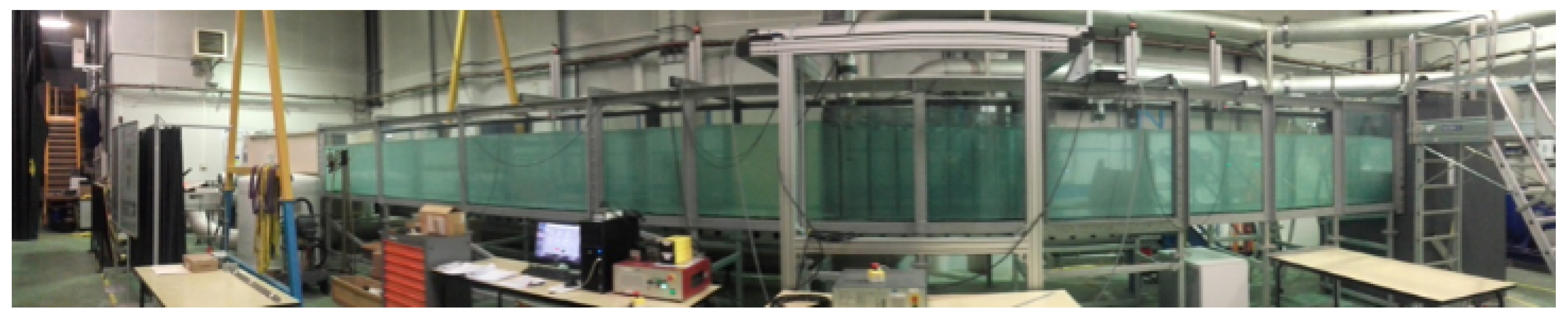
2.1. Experimental Setup
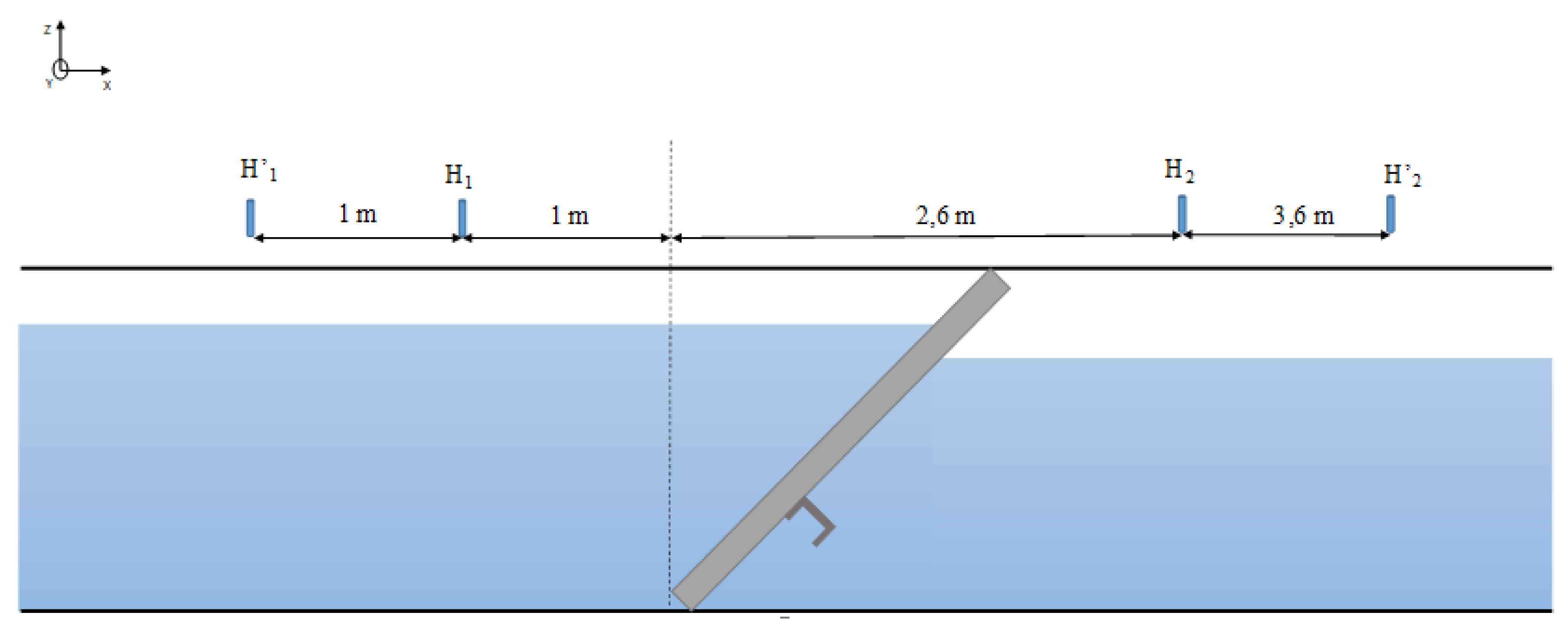
2.2. Measurements
2.3. Calculation
2.4. Methodology of Modeling
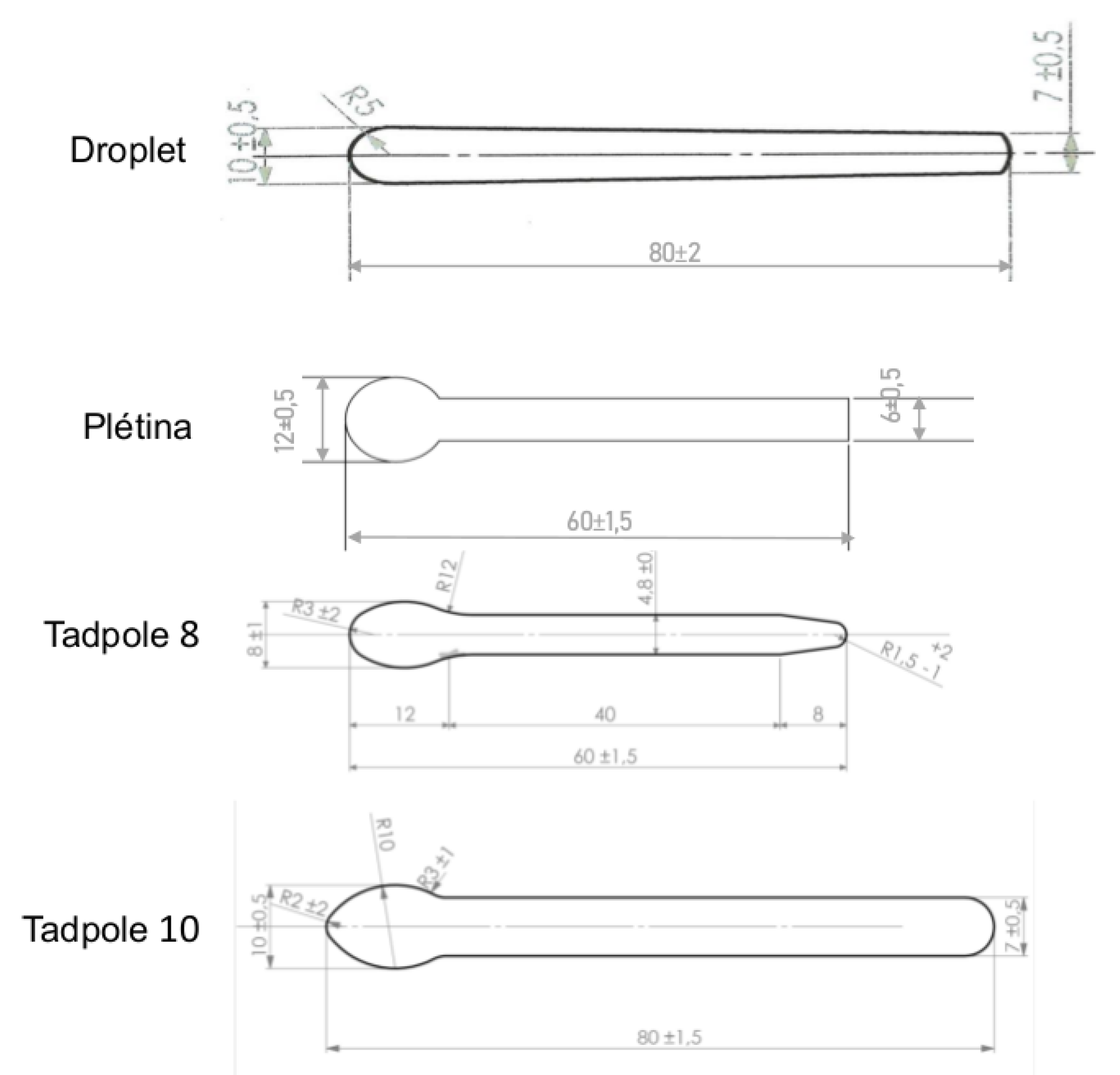
2.4.1. Bar Shape
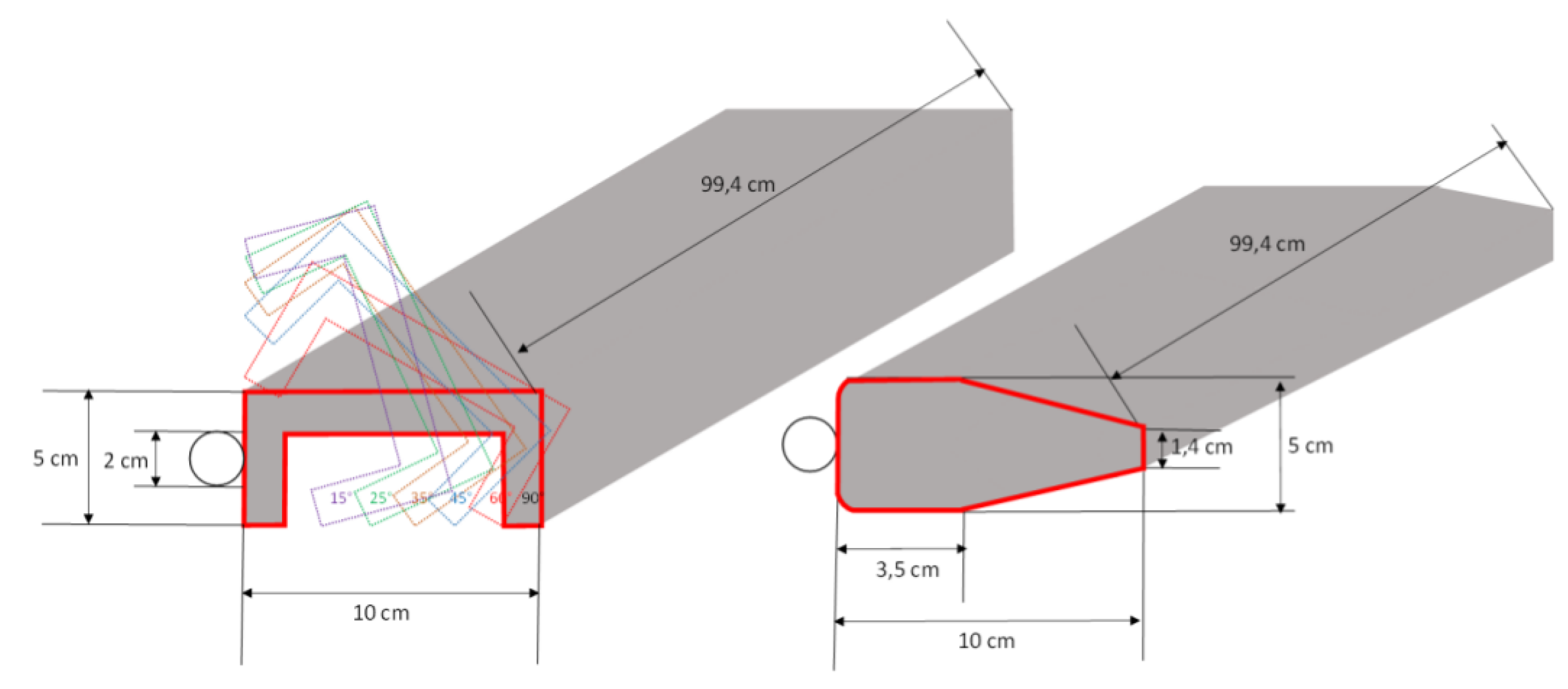
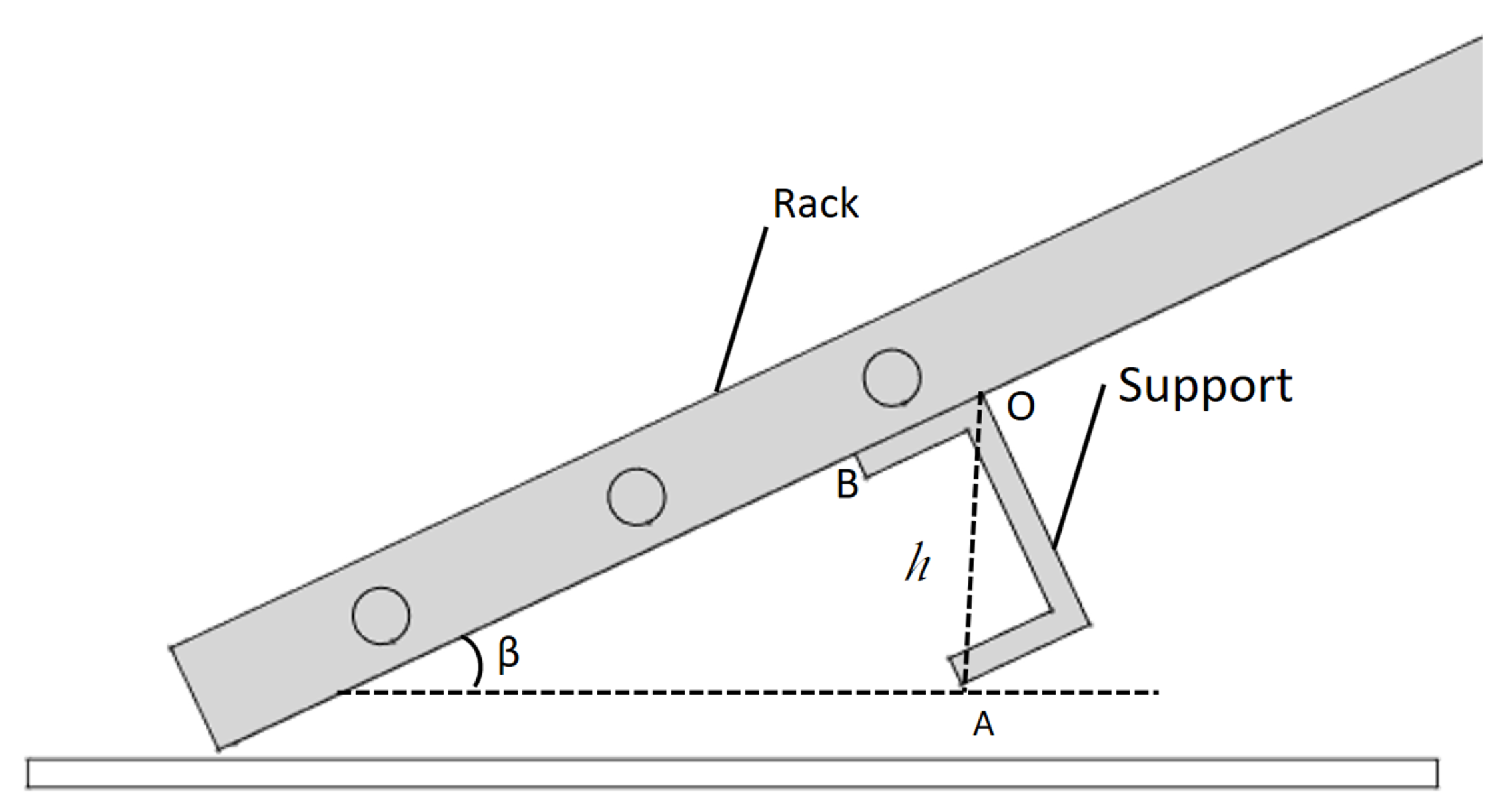
2.4.2. Support
- If profiled shape, h is constant.
- If U-shaped, .
3. Results
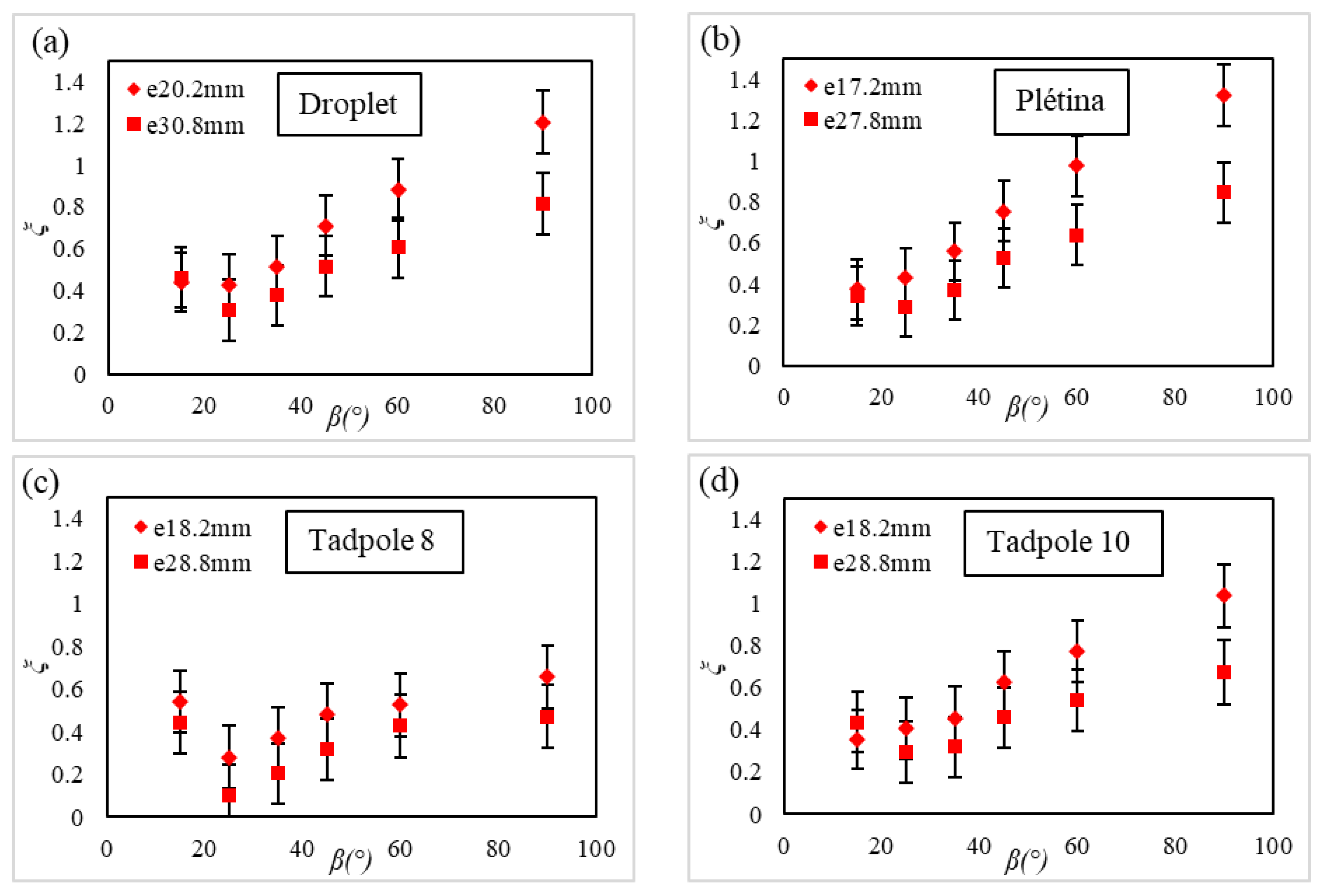
3.1. Effect of the Bar Profiles on Head Losses
3.1.1. Experimental Head Loss Coefficients
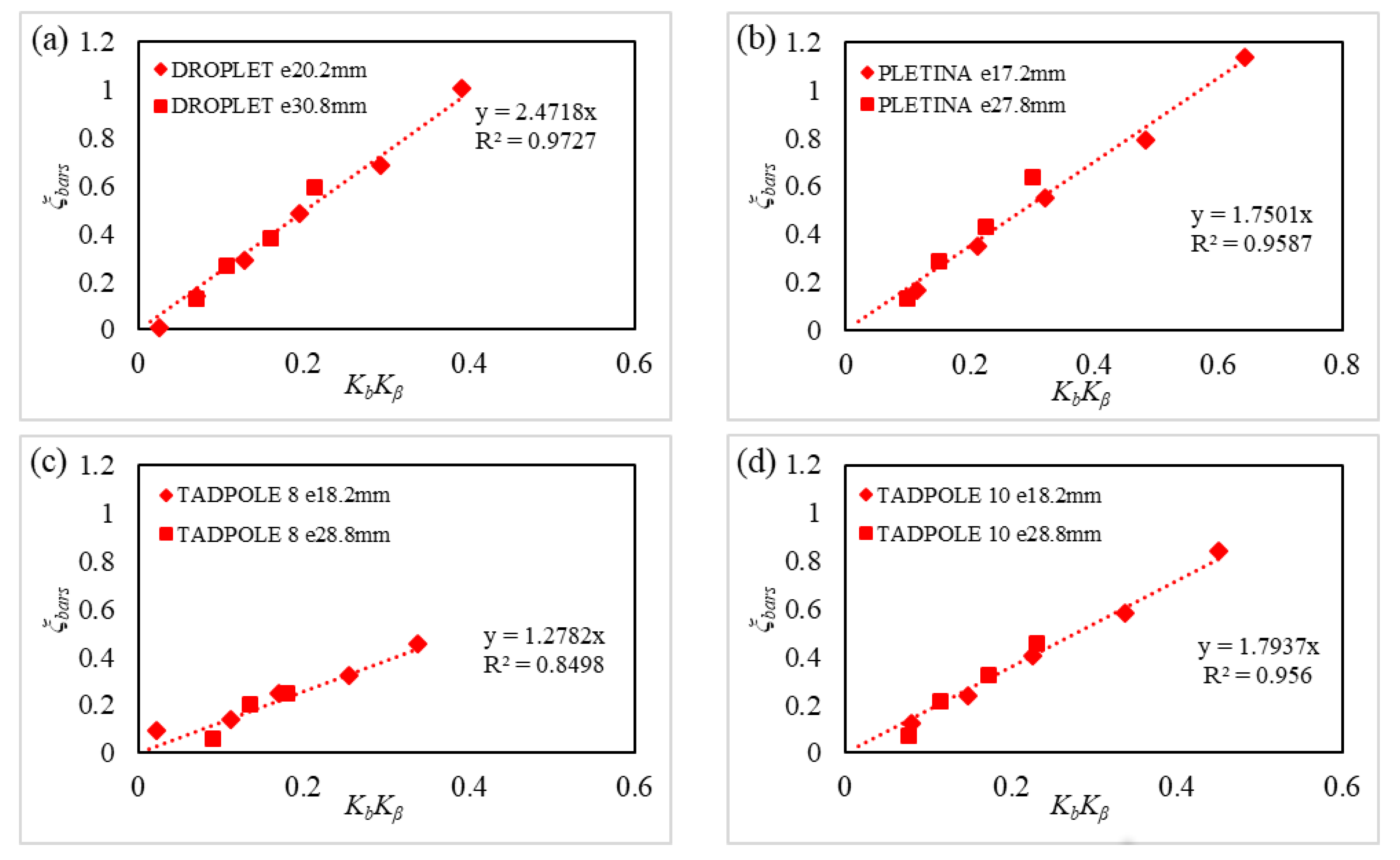
3.1.2. Modeled Head Loss Coefficients
3.2. Effect of the Support on Head Losses
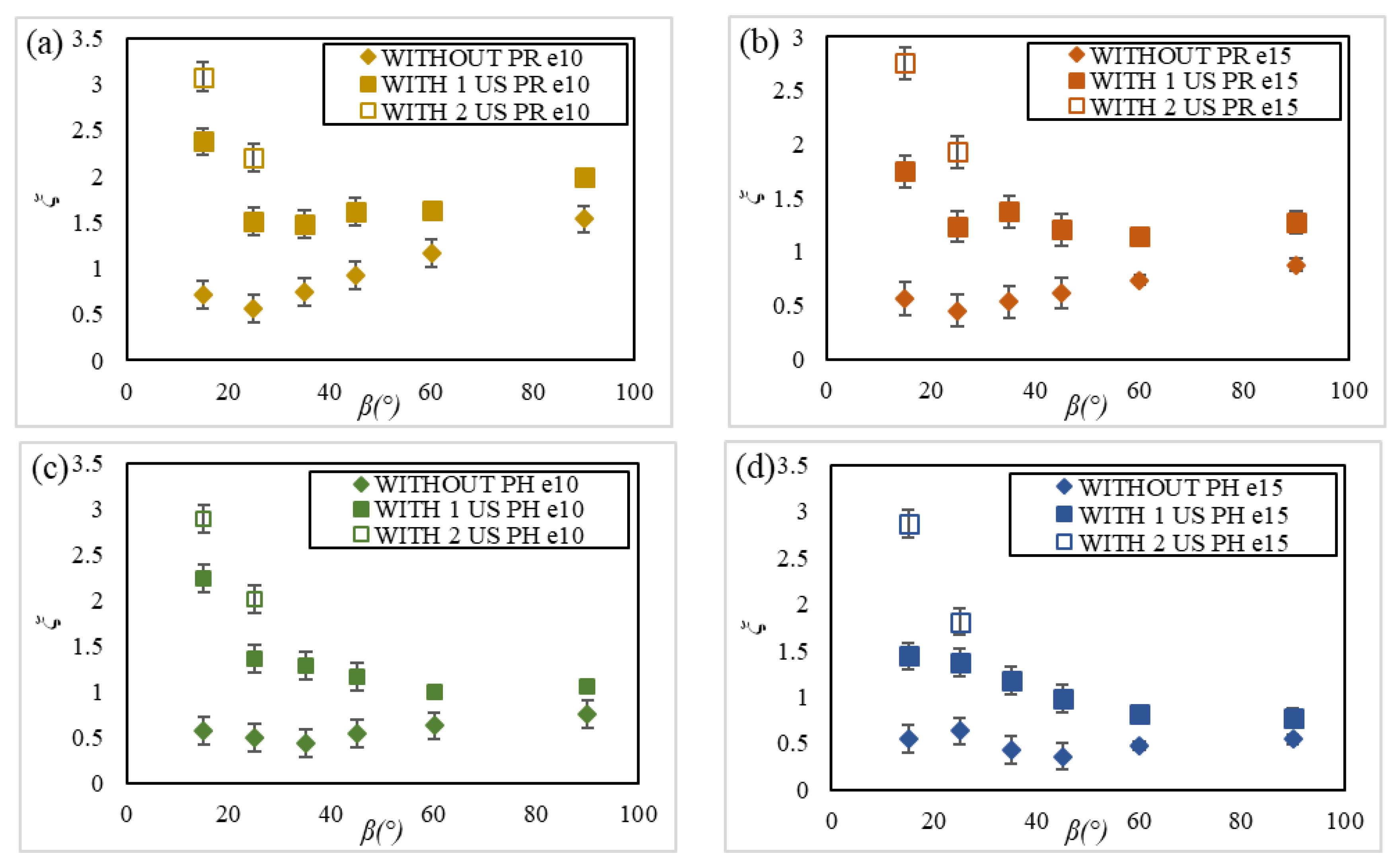
3.2.1. Experimental Comparison with and without U-Shaped Supports
3.2.2. Experimental Comparison with and without the Profiled Support
3.2.3. Modeled Head Loss Coefficients
4. Conclusions
Author Contributions
Funding
Acknowledgments
Conflicts of Interest
Abbreviations
| Bar shape coefficient (-) | |
| b | Bar thickness (m) |
| p | Bar depth (m) |
| B | Channel width (m) |
| e | Bar spacing (m) |
| h | Projection of the support diagonal (m) |
| g | Gravitation acceleration (m) |
| , | Upstream and downstream head water (m) |
| Blockage ratio due to the bars (-) | |
| Blockage ratio due to the spacing bars (-) | |
| Blockage ratio due to the supports (-) | |
| , | Upstream and downstream velocities (m) |
| Angle of inclination () | |
| Ratio of the bars (-) | |
| Ratio of the angle of inclination (-) | |
| U-shaped support coefficient (-) | |
| Profiled support coefficient (-) | |
| Head loss coefficient due to the bars (-) | |
| Head loss coefficient due to the spacers (-) | |
| Head loss coefficient due to the supports (-) | |
| Total head loss coefficient (-) |
Appendix A

| Bar Shape | Droplet | Plétina | Tadpole 8 | Tadpole 10 | ||||||
|---|---|---|---|---|---|---|---|---|---|---|
| e (mm) | 20.2 | 30.8 | 17.2 | 27.8 | 18.2 | 28.8 | 18.2 | 28.8 | ||
| () | ||||||||||
| 15 | 0.44 | 0.46 | 0.37 | 0.34 | 0.54 | 0.44 | 0.36 | 0.44 | ||
| 25 | 0.43 | 0.30 | 0.43 | 0.29 | 0.28 | 0.10 | 0.41 | 0.29 | ||
| 35 | 0.51 | 0.38 | 0.56 | 0.37 | 0.37 | 0.20 | 0.46 | 0.32 | ||
| 45 | 0.71 | 0.52 | 0.75 | 0.52 | 0.48 | 0.32 | 0.62 | 0.46 | ||
| 60 | 0.88 | 0.60 | 0.98 | 0.64 | 0.53 | 0.43 | 0.77 | 0.54 | ||
| 90 | 1.21 | 0.81 | 1.32 | 0.85 | 0.66 | 0.47 | 1.04 | 0.67 | ||
| () | Support Shape | Without | With 1 U-Shaped | With 2 U-Shaped | With Profiled Shape | ||||||
|---|---|---|---|---|---|---|---|---|---|---|---|
| Bar Profile | PR | PH | PR | PH | PR | PH | PR | PH | |||
| e (mm) | |||||||||||
| 15 | 10 | 0.71 | 0.58 | 2.43 | 2.24 | 3.08 | 2.90 | 0.82 | 0.70 | ||
| 15 | 0.56 | 0.55 | 1.75 | 1.44 | 2.75 | 2.87 | 0.69 | 0.64 | |||
| 25 | 10 | 0.56 | 0.50 | 1.51 | 1.36 | 2.20 | 2.02 | 0.66 | 0.55 | ||
| 15 | 0.45 | 0.63 | 1.23 | 1.37 | 1.93 | 1.81 | 0.53 | 0.66 | |||
| 35 | 10 | 0.75 | 0.44 | 1.49 | 1.28 | - | - | 0.79 | 0.45 | ||
| 15 | 0.53 | 0.43 | 1.37 | 1.18 | - | - | 0.58 | 0.50 | |||
| 45 | 10 | 0.93 | 0.54 | 1.61 | 1.16 | - | - | 0.96 | 0.64 | ||
| 15 | 0.61 | 0.36 | 1.21 | 0.98 | - | - | 0.64 | 0.44 | |||
| 60 | 10 | 1.17 | 0.63 | 1.63 | 0.99 | - | - | 1.22 | 0.71 | ||
| 15 | 0.74 | 0.47 | 1.14 | 0.82 | - | - | 0.75 | 0.50 | |||
| 90 | 10 | 1.53 | 0.75 | 2.00 | 1.06 | - | - | 1.70 | 0.89 | ||
| 15 | 0.88 | 0.54 | 1.27 | 0.78 | - | - | 0.97 | 0.63 | |||
References
- Courret, D.; Larinier, M. Guide pour la Conception de Prises d’Eau Ichtyocompatibles pour les Petites Centrales Hydroelectriques; Technical Report RAPPORT GHAAPPE RA.08.04; ONEMA: Toulouse, France, 2008. [Google Scholar]
- Meusburger, H. Energieverluste an Einlaufrechen von Flusskraftverken. Ph.D. Thesis, ETH Zurich, Zurich, Switzerland, 2002. [Google Scholar]
- Ebel, G. Fish Protection and Downstream Passage at Hydro Power Stations; Handbuch Rechen- und Bypass Systeme; Buro fur Gewasserokologie und Fischereibiologie Dr. Ebel: Galle, Germany, 2013. [Google Scholar]
- Raynal, S. Etude experimentale et numérique des grilles ichtyocompatibles. Ph.D. Thesis, University of Poitiers, Poitiers, France, 2013. [Google Scholar]
- Calles, O.; Karlsson, S.; Vezza, P.; Comoglio, C.; Tielman, J. Success of a low-sloping rack for improving downstream passage of silver eels at a hydroelectric plant. Freshw. Biol. 2013, 58, 2167–2180. [Google Scholar] [CrossRef]
- Tomanova, S.; Courret, D.; Alric, A.; De Oliveira, E.; Lagarrigue, T.; Tetard, S. Protecting efficiently sea-migrating salmon smolts from entering hydropower plant turbines with inclined or oriented low bar spacing racks. Ecol. Eng. 2018, 122, 143–152. [Google Scholar] [CrossRef]
- Albayrak, I.; Kriewitz, C.; Hager, W.; Boes, R. An experimental investigation on louvers and angled bar racks. J. Hydraul. Res. 2018, 56, 59–75. [Google Scholar] [CrossRef]
- Albayrak, I.; Maager, F.; Boes, R. An experimental investigation on fish guidance structures with horizontal bars. J. Hydraul. Res. 2019, 1–15. [Google Scholar] [CrossRef]
- Boettcher, H.; Galb, R.; Aufleger, M. Experimental hydraulic investigation of angled fish protection systems—Comparison of circular bars and cables. Water 2019, 11, 1056. [Google Scholar] [CrossRef]
- Katopodis, C.; Williams, J.G. The development of fish passage research in a historical context. Ecol. Eng. 2012, 48, 8–18. [Google Scholar] [CrossRef]
- Kirschmer, O. Untersuchungen uber den gefallsverlust an rechen. In Mitteilungen des Hydraulischen Institutes of der Technischen Hochschule Munchen; Thoma, D., Ed.; De Gruyter Oldenbourg: Munich, Germany, 1926. [Google Scholar]
- Mosonyi, E. Wasserkraftwerke, Band I, Niederdruckanlagen; VDI: Dusseldorf, Germany, 1966. [Google Scholar]
- Zimmermann, J. Widerstand Schrag Angestromter Rechengitter; Karlsruhe Institute of Technology: Karlsruhe, Germany, 1969. [Google Scholar]
- Meusburger, H.; Volkart, P.; Minor, H. A new improved formula for calculating trashrack loosses. In Proceedings of the 29th Congress IAHR—International Association of Hydraulic Engineering and Research, Beijing, China, 16–21 September 2001; pp. 804–809. [Google Scholar]
- Clark, S.; Tsikata, J.; Haresign, M. Experimental study of energy loss through submerged trashracks. J. Hydraul. Res. 2010, 48, 113–118. [Google Scholar] [CrossRef]
- Idelcik, I.E. Mémento de pertes de charge—Coefficients de pertes de charge singulières et pertes de charge par frottement. In Collection de la Direction des Études et Recherches d’Electricité de France; Eyrolles: Paris, France, 1979. [Google Scholar]
- Escande, L. Pertes de charge à la traversée des grilles. In Compléments d’Hydraulique; Privat: Toulouse, France, 1947. [Google Scholar]
- Spangler, J. Investigations of the loss through trash racks inclined obliquely to the stream flow. In Hydraulic Laboratory Practice; ASME: New York, NY, USA, 1929; pp. 461–470. [Google Scholar]
- Scruton, C.; Newberry, C.W. On the estimation of wind loads for building and structural design. Proc. Inst. Civ. Eng. 1929, 25, 97–126. [Google Scholar] [CrossRef]
- Raynal, S.; Courret, D.; Chatellier, L.; David, L. An experimental study on fish-friendly trashracks Part 1. Inclined trashracks. J. Hydraul. Res. 2013, 51, 56–66. [Google Scholar] [CrossRef]
- Beaulieu, C.; Pineau, G.; Ballu, A.; David, L.; Calluaud, D. Démarche d’estimation des incertitudes de mesure dans un laboratoire de recherche: Apport et perspectives- exemple d’un laboratoire de recherche en hydrologie des milieux aquatiques. In Proceedings of the 17th International Congress of Metrology, Paris, France, 21–24 September 2015; pp. 97–108. [Google Scholar]
- Joint Committee for Guides in Metrology—JCGM. Guide to the Expression of Uncertainty in Measurement; JCGM: Geneva, Switzerland, 2008; p. 122. Available online: https://www.bipm.org/utils/common/documents/jcgm/JCGM_100_2008_E.pdf (accessed on 20 March 2020).


| Parameters | Values | Units |
|---|---|---|
| Bar spacing e | 17.2/18.2/20.2/27.8/28.8/30.8 | (mm) |
| Angle of inclination | 15/25/35/45/60/90 | () |
| Discharge Q | 0.29/0.48/0.5 | (ms) |
| Upstream water depth | 0.42/0.67/0.7 | (m) |
| Approach velocity | 0.72 | (ms) |
| Reynolds number | 720,000 | (-) |
| Bar-Reynolds number | 3600/5760/7200/8640 | (-) |
| Froude number | 0.27/0.28/0.35 | (-) |
| Bar Shape | Maximum Thickness b (mm) | Depth p (mm) | e/b (-) |
|---|---|---|---|
| Droplet | 10 | 80 | 2/3.1 |
| Plétina | 12 | 60 | 1.4/2.3 |
| Tadpole 8 | 8 | 60 | 2.3/3.6 |
| Tadpole 10 | 10 | 80 | 1.8/2.9 |
| Hydrodynamic | 5 | 40 | 1/2/3/4 |
| Rectangular | 5 | 40 | 1/2/3/4 |
| Bar Shape | Droplet | Plétina | Tadpole 8 | Tadpole 10 | Hydrodynamic | Rectangular |
|---|---|---|---|---|---|---|
| Bar coefficient | 2.47 | 1.75 | 1.27 | 1.79 | 2.10 | 3.85 |
| ratio (%) | 64.2 | 45.5 | 33 | 46.5 | 54.5 | 100 |
© 2020 by the authors. Licensee MDPI, Basel, Switzerland. This article is an open access article distributed under the terms and conditions of the Creative Commons Attribution (CC BY) license (http://creativecommons.org/licenses/by/4.0/).
Share and Cite
Lemkecher, F.; Chatellier, L.; Courret, D.; David, L. Contribution of Different Elements of Inclined Trash Racks to Head Losses Modeling. Water 2020, 12, 966. https://doi.org/10.3390/w12040966
Lemkecher F, Chatellier L, Courret D, David L. Contribution of Different Elements of Inclined Trash Racks to Head Losses Modeling. Water. 2020; 12(4):966. https://doi.org/10.3390/w12040966
Chicago/Turabian StyleLemkecher, Fatma, Ludovic Chatellier, Dominique Courret, and Laurent David. 2020. "Contribution of Different Elements of Inclined Trash Racks to Head Losses Modeling" Water 12, no. 4: 966. https://doi.org/10.3390/w12040966
APA StyleLemkecher, F., Chatellier, L., Courret, D., & David, L. (2020). Contribution of Different Elements of Inclined Trash Racks to Head Losses Modeling. Water, 12(4), 966. https://doi.org/10.3390/w12040966