1. Introduction
Global warming leads to ocean thermal expansion and melting of ice sheets in Greenland and Antarctica and consequently causes sea level rise (SLR) [
1]. The observed data support an increase of about 1.7 mm/year in the average global sea level rise in the 20th century, which is projected to increase about one more meter by the end of the current century [
2]. Local SLR can be much more than these global averages. For instance, the local sea level rise rate is estimated to be about 4.4–8.8 mm/y in Murgia and Salento in Southern Italy [
3]. The National Climate Assessment (NCA) reported that sea levels may rise up to 2 m along the United States coastlines by 2100 [
4]. Local sea level rise estimates for Acapulco, Mexico, Manila, Philippines, and in Chomklao, Thailand are 7.5 mm/y, 14 mm/y, and 16.5 mm/y, respectively [
5,
6,
7].
Most of the studies on climate change and flooding issues have addressed anthropogenic changes of rainfall intensity and frequency as well as land-use changes due to development and urbanization [
8,
9,
10]. These changes substantially alter the peak flow, volume, and duration of flooding and exacerbate domestic inundation areas [
11]. In addition to impacts due to rainfall and land-use changes, there is a significant marine flooding risk to highly-populated low-lying cities in coastal areas, including major economic centers such as London, New York, Shanghai, and Mumbai [
12]. Globally, it is estimated that more than 20 million people live below the normal high tide elevation and more than 200 million people are under threat of extreme sea level events caused by storms [
12]. The United States National Oceanic and Atmospheric Administration (NOAA) reports that about 3.2 billion people worldwide live and work within 200 km of a coastline [
13,
14], which can be adversely affected by SLR-related closure of access roads and reduced functionality of other infrastructure.
In the United States, the state of Florida ranked 3rd for the number of National Flood Insurance Program (NFIP) claims in the last four decades [
15]. The average SLR in Florida for two time horizons, namely 2060 and 2100, are estimated to be about 0.76 m (2.5 feet) and 1.95 m (6.4 feet), respectively [
4]. Meanwhile, about 10% of Floridians live in areas with a ground elevation below 1.5 m [
16]. Senate Bill (SB) 1094 was passed in 2015 by the Florida legislature to consider the future flood risk from storm surge and sea level rise in certain portions of local government master plans. Nevertheless, stormwater system design in the state is still, generally, based on assumptions of stationary sea level conditions, although the need for accounting for nonstationary future conditions in hydrologic analyses has been recognized [
17,
18,
19]. The cost increases associated with designs that account for SLR and the combined effects of SLR and rainfall increase are significantly lower when compared to the cost to retrofit a system after construction [
20].
Retention ponds are an integral component of stormwater management plans in Florida, as well as many other areas. Retention ponds help protect the infrastructure and ecosystems in coupled natural-human systems. They are typically designed to maintain the predevelopment runoff condition by detaining the outflow or infiltrating the additional runoff generated by impervious areas, and by providing pollutant removal through settling and biological uptake [
11,
21]. The outlet structure for retention ponds is designed to provide complete storage and percolation of a specified treatment volume to remove pollutants.
This study examines how the reliability of stormwater retention ponds in regulating runoff and removing pollutants can be affected by groundwater changes due to SLR. SLR can increase groundwater-related flooding by raising groundwater tables [
22,
23,
24]. The loss of percolation capability due to reduced infiltration and subsurface storage because of high groundwater tables can have a significant impact on the treatment capacity provided by a retention system. Using a case study from Tampa Bay, Florida, we demonstrate the importance of accounting for SLR-related higher groundwater tables in the design of retention ponds to prevent poor performance in the long run.
2. Study Area and Regulatory Framework
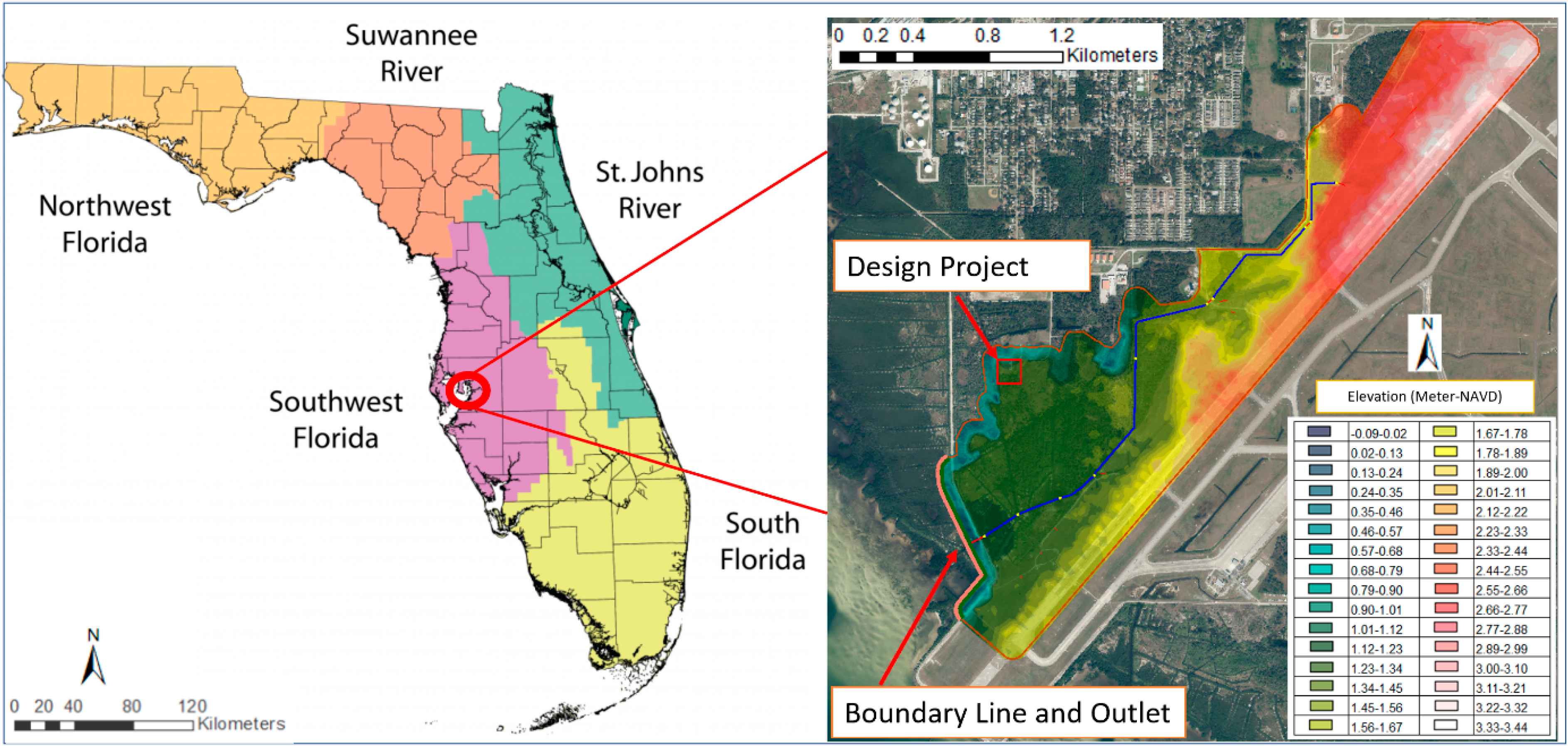
The study area covers 49 hectares (122-acres) in the Southwest Florida Water Management District (SWFWMD). The project area is connected to Tampa Bay, which is classified as impaired, and, ultimately, the Gulf of Mexico to the southwest (
Figure 1). Florida has enacted some of the most restrictive environmental requirements in the United States to protect its water resources and natural habitats. New development is often regulated through the state’s Environment Resource Permit (ERP) requirements. The Florida Department of Environmental Protection (FDEP) has delegated this responsibility to regional water management districts.
Two major regulations must be followed to obtain an ERP for a new development [
25]. First, stormwater pollutant removal must be provided prior to discharging project runoff off-site, including discharge to public drainage systems or other water bodies, to ensure the new development does not increase pollutant loads. Second, off-site peak discharge for the post-development condition should not exceed pre-development discharge from the property. SWFWMD allows an exemption for the pre- and post-discharge requirement when the receiving point is a tidal water body, such as the Gulf of Mexico. In this situation, there is no requirement on peak rate of discharge. Since the discharge point for this study has about 1.5-km (~1 mile) distance to the Bay and is not directly discharging to it, the peak rate requirements for retention pond design were considered. The off-site discharge is typically estimated using the rate of discharge for 25-year, 24-h storm for open basins and the volume discharge for 100-year, 24-h storm for closed basins.
There are multiple ways to address these requirements. The treatment volume is determined based upon the methodology chosen for the project, which depends on soil and groundwater conditions at the project site. Two of the most commonly used approaches are retention- and detention-based methodologies. Retention methodology, which is applied in this study, provides storage of the treatment volume and recovery of that storage through percolation or evaporation over several days. Detention provides temporary storage of the treatment volume in a pond equipped with a control structure and bleed-down device that slowly releases the treatment volume to surface water over several days. Based on the ERP [
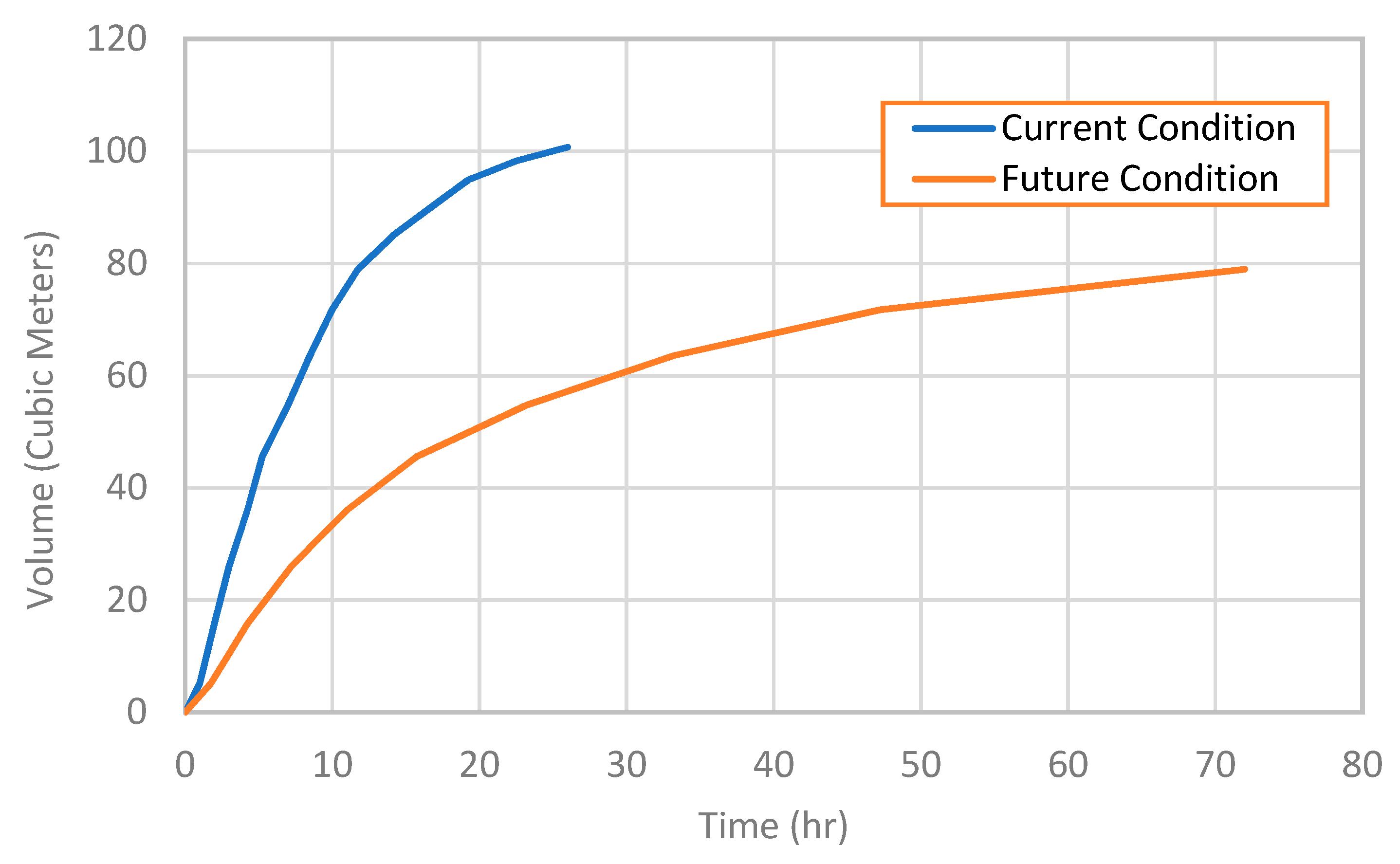
25], the required treatment volume for the considered project is one inch (2.54 cm) over the entire development area. This volume must be recovered within 72 h, so the treatment volume is available to capture and treat runoff from subsequent storms. The total outflow for existing and post-project conditions are evaluated to illustrate the performance of the pond under these two conditions.
3. Input Data
Primary input data include rainfall, evapotranspiration, soil properties, land-use map, and tide data. Long-term rainfall data from Next Generation Weather Radar (NEXRAD) was used in this study to perform a continuous simulation of the pond’s performance under SLR. Calibrated 15-min NEXRAD rainfall data are available on a 2-km grid [
26]. Atlas 14 rainfall intensity data [
27] and the Soil Conservation Service (SCS) Type II Florida Modified rainfall distribution were used for synthetic design storm simulations. Based on Atlas 14, the 25-year, 24-h rainfall for the study area is about 21 cm. The potential evapotranspiration (PET), which is a significant loss in continuous simulations, was obtained from United States Geologic Survey (USGS). The PET data were provided in the same spatial grid as the NEXRAD data on a daily time scale.
The soils zone map and related parameters for modeling infiltration using the Green–Ampt method (e.g., porosity and hydraulic conductivity) were obtained directly or based on data from the National Resources Conservation Service database [
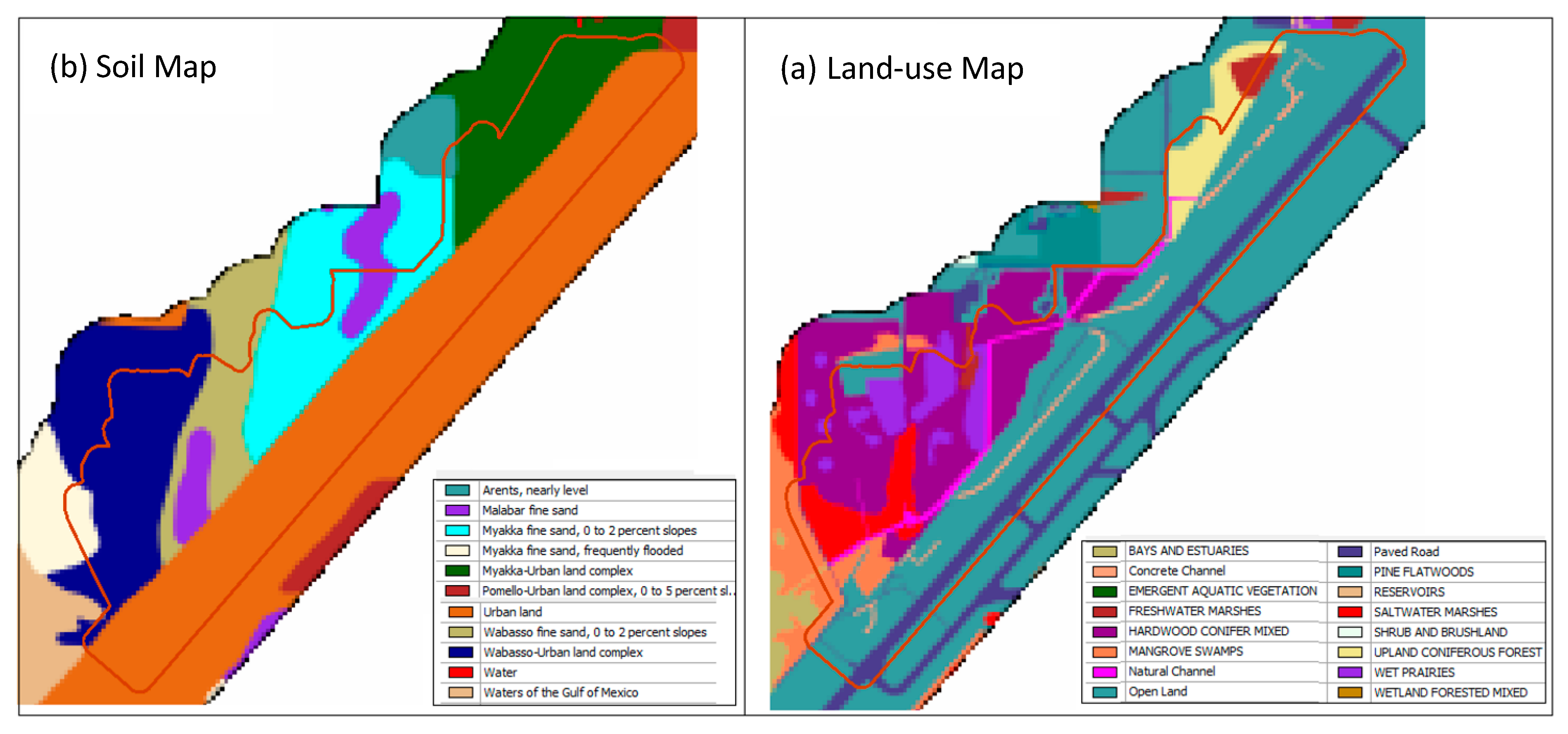
28]. The majority of the project site has good soils with high infiltration and high porosity (
Figure 2a and
Table 1). The groundwater table, however, is relatively close to the ground surface, especially in the Tampa Bay area. Land-use data available from the SWFWMD were used along with post development land-use for developing TR-55 [
29] impervious area lookup tables (
Figure 2b). Existing land-use on the project site consists of mixed hardwood conifer and open land. Post development land-use conditions include commercial building space, parking lot, and a new retention pond.
The Manning’s roughness values were also determined based on the land-use analysis for use by the surface water model (see
Section 4.1). Two different Manning’s n values were applied for representing shallow flow (i.e., up to 0.914 m (3 ft)) and deep flow (i.e., greater than 0.914 m) conditions to capture greater roughness close to the ground surface in shallow flow compared with deep waters, which will have smaller Manning’s roughness values. The study area is mostly covered by dense tidal marsh plants and brushes close to the ground surface. The density of the canopy declines as the elevation increases, typically reaching about 0.914 m above the ground level, which is the basis for the depth threshold for applying deep Manning’s roughness coefficient. The model generates vertically varied Manning’s n values up to 0.914 m above the ground elevation based on an exponential equation using the specified shallow and deep flow Manning’s n values [
30]. Deep flow Manning’s roughness coefficients are used when the flow depth exceeds the 0.914 m threshold.
Table 2 shows the Manning’s roughness values for different land-use types.
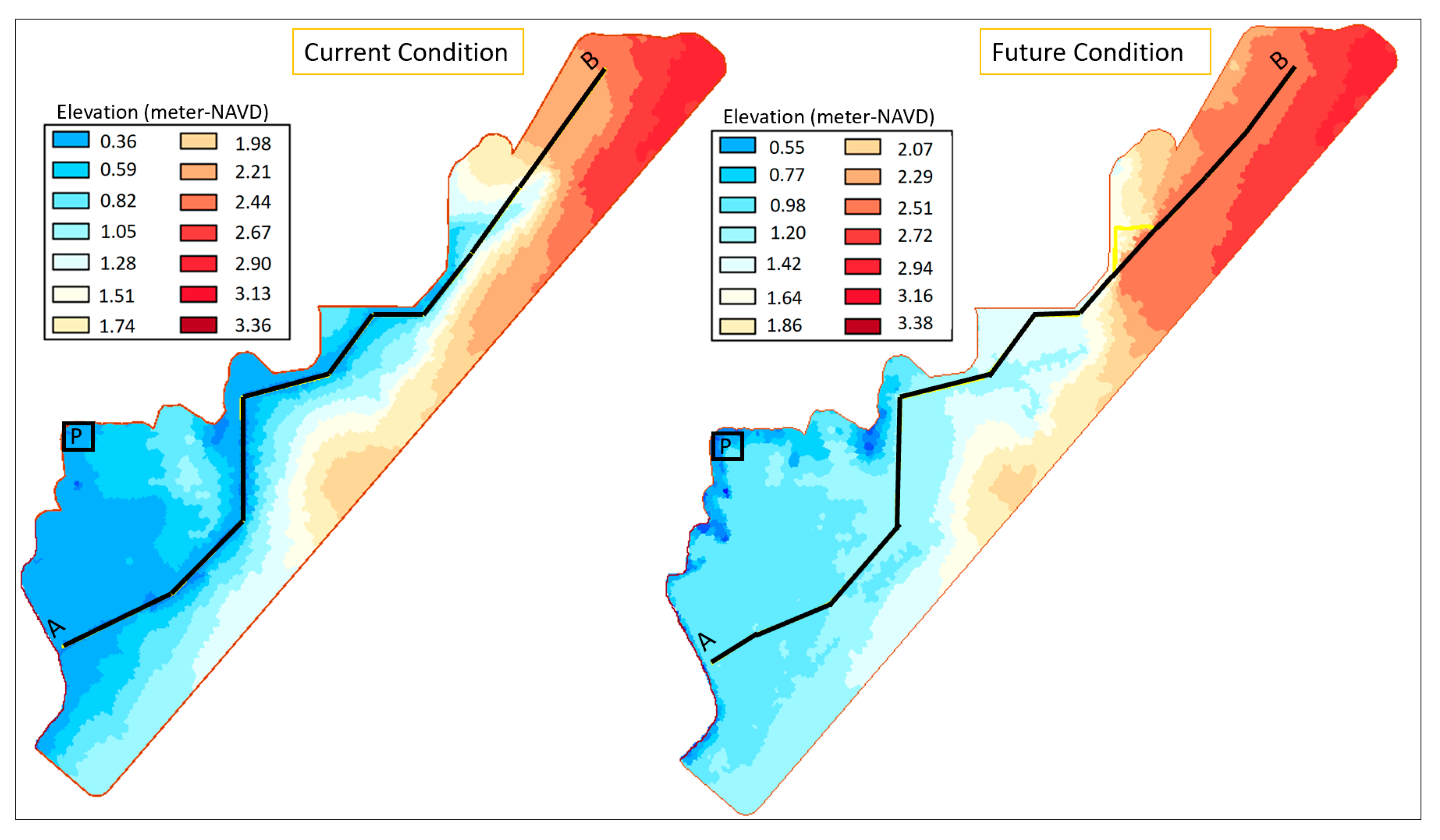
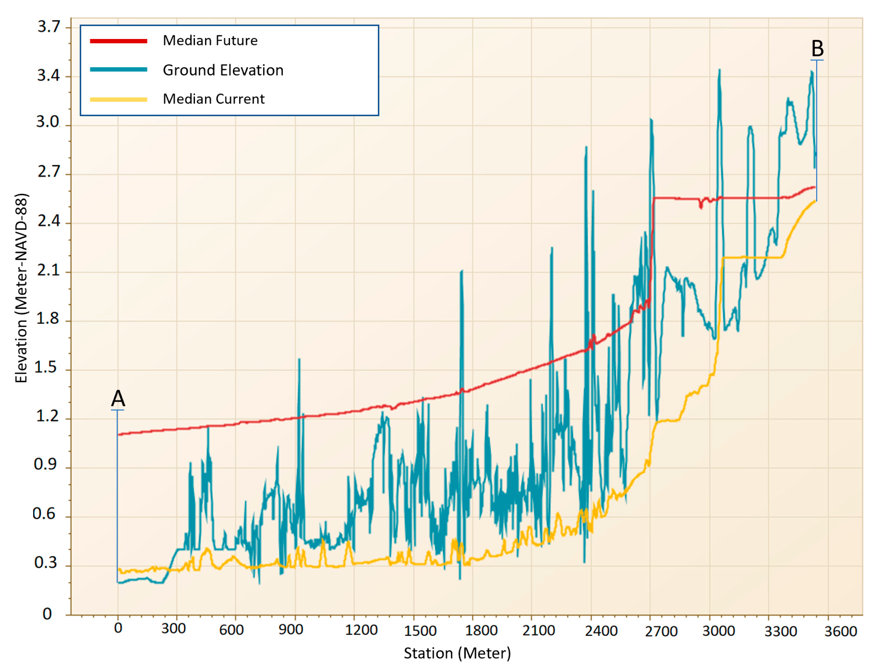
Tide data for a nearby Tampa Bay gage (station ID 8726520) were obtained from NOAA to set the sea level boundary conditions for this study. The mean high water elevation (MHW) is 0.6 m (1.98 feet), above the mean lower low water elevation (MLLW), which is 0.15 m based on North American Datum of 1988 (M-NAVD-88). For surface water/groundwater modeling and the SLR study, ground elevation plays a key role. Therefore, a 1.5 m LiDAR-based digital elevation model (DEM) was used in this study. The FDEP has data for various hydrogeologic components including Florida Aquifer Units (FAU) and potentiometric surface, which were also used in this study. The projected SLR for a time horizon of 2060 is about 79 cm (2.6 feet), which was determined from NCA [
4] to adjust tailwater for the future conditions simulation.
4. Modeling Framework
4.1. Hydrologic and Hydraulic Model Structure and Components
An integrated surface water and groundwater model was developed to evaluate the effects that SLR-related groundwater changes may have on the performance and reliability of retention pond functions. The Interconnected Channel and Pond Routing (ICPR) model [
30], which includes a fully-integrated 1D/2D surface water module coupled with a 2D groundwater module was applied. The coupled model allows interaction between surficial aquifer systems and surface water bodies.
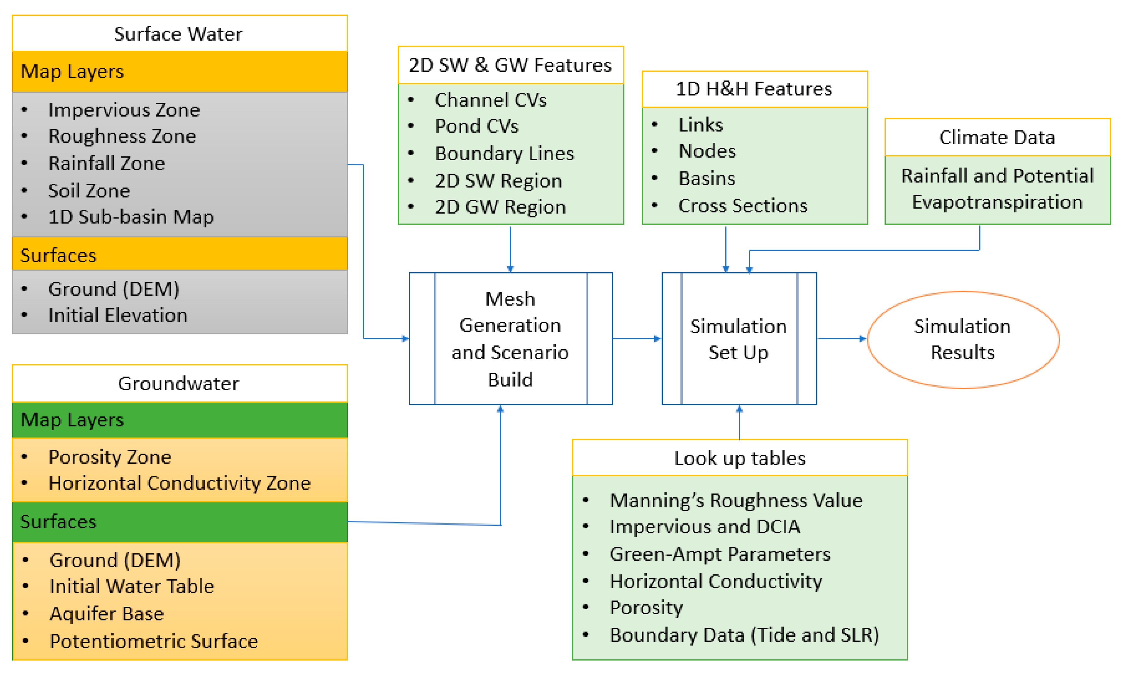
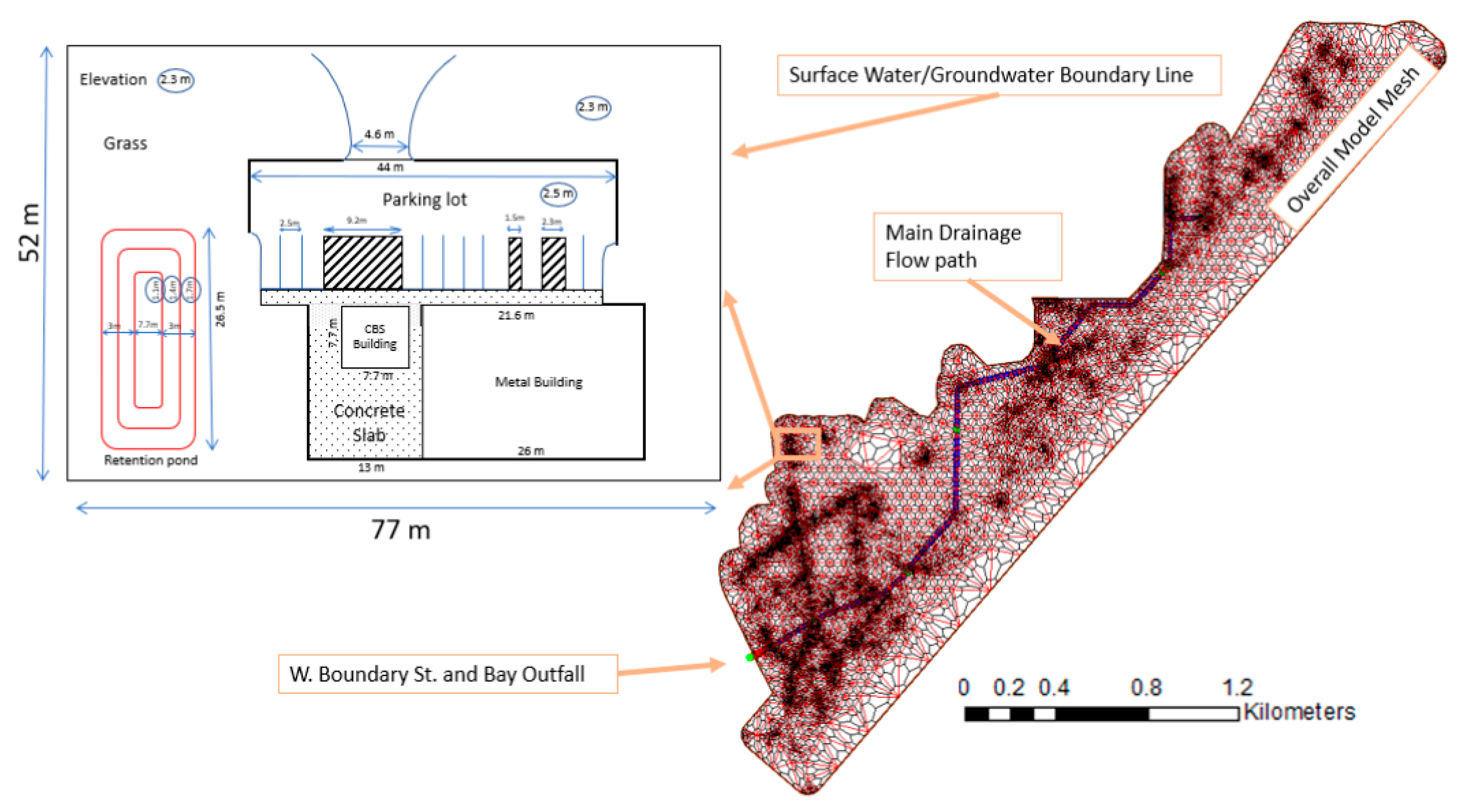
Figure 3 shows the general structure and major features of an ICPR 2D model. ICPR has a pre-processer for mesh generation as well as a scenario builder that must be executed before the simulation is conducted. The model generates triangular meshes for both surface water and groundwater calculations and parameterizes all components for the simulation. Several of the 2D features in ICPR, such as pond control volumes and channel control volumes, force the creation of vertices (2D nodes) along their respective polygons during mesh creation.
The scenario builder uses various map layers and surfaces with the mesh, honeycombs and triangles to calculate the parameters required by each 2D link (triangle sides) and 2D node (vertices) for the hydrologic and hydraulic (H&H) calculations. During the simulation process, the model reads parameters like roughness values, impervious percentage, and hydraulic conductivity from lookup tables related to each map layer. Climate data and 1D H&H input data are independent components of an ICPR model and they can be added to the model database after 2D scenario building before simulation.
For surface water, the initial ground condition was assumed to be dry and the initial elevation was the same as the ground elevation. For groundwater, the initial water table elevation was estimated based on a digital elevation model (DEM) and water table information from the NRCS soil database. It should be noted that for continuous simulations, a “warm-up” run was executed for a couple of months to allow the initial water table to stabilize. The warm-up simulation was then used as a “hot start” for the continuous simulations. The average of wet season water elevations (June through October) was used as the initial water table for discrete event simulations.
4.2. Excess Rainfall, Infiltration, and Groundwater
Both event-based simulations and continuous simulations were considered in this study. The Green–Ampt method [
32] provided in ICPR is a useful rainfall-runoff method that allows water tracking during hydrologic simulations throughout the soil column, including dry and wet periods. The Green–Ampt method is based on Darcy’s law:
where
is the vertical hydraulic conductivity (m/day) and
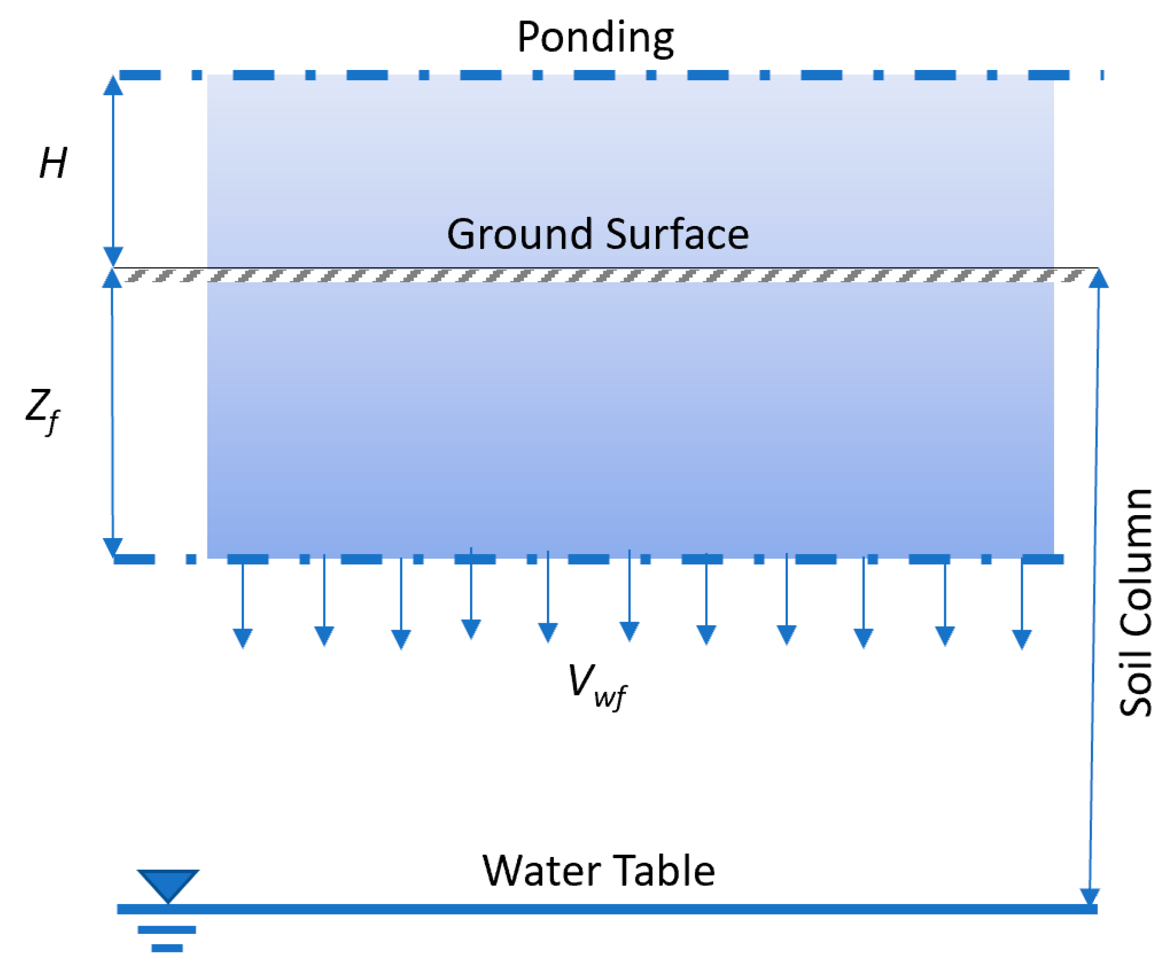
I is the gradient defined as the summation of ponding head (
H), saturated wetting front below the ground (
), and the capillary suction head (
) as shown in
Figure 4.
ICPR estimates
hc based on moisture content and bubble pressure from soil data (
Table 1). Velocity of the wetting front is estimated using the following equation:
where
n is the fillable porosity.
Integrating Equation (3) for time 0 to
t0 and
between 0 to
yields:
Equation (4) is used to simulate decay of the infiltration rate.
is the maximum amount of water that can infiltrate and excess water above the ground represents rainfall excess or ponded storage. In reality, rainfall is not always sufficient to saturate the soil column and evapotranspiration (ET) can become a significant loss term. Therefore, ICPR uses a modified Green–Ampt method which is explained in the ICPR user manual [
30]. Vertical water movement is only conveyed through unsaturated soil zones and horizontal conductivity is applied for water transfer in saturated soil zones. Evapotranspiration is allowed on the surface to the root depth zone which can be defined in the ICPR model. Deep percolation can also be considered, including use of the potentiometric surface data to provide estimates of gradient and leakance, although leakance was not considered in this study (see
Section 4.5).
4.3. One-Dimensional Surface Water Components
The ICPR 1D surface model has three primary features: nodes, links, and basins. The basin feature represents areas that contribute runoff to nodes and require a number of parameters for excess rainfall and routing calculations, including basin area, impervious and directly connected impervious area (DCIA), time of concentration, etc. Basins are used for loading of 1D nodes. Areas modeled using 2D surfaces do not require basin features (2D surface modeling is explained in the next section). A basin is associated with a node. Nodes represent locations in the model where mass balance is tracked and are used to represent ponds or drainage system junctions; the storage data for a node is typically contained within the basin assigned to that node. Runoff transfers from one node to another node through links which represent water conveyance features such as culverts, channels, overland flow weirs or other types of hydraulic connections. ICPR has three options for flow rate calculations through channels and pipes: the energy equation, the momentum equation, and the diffusive wave equation [
30]. The energy method was used for flow calculations in this study:
where subscripts 1 and 2 represent conditions at nodes 1 and 2, respectively;
Z represents elevation (m);
α1 and
α2 are energy loss coefficients;
V represents velocity (m/s);
g is gravitational acceleration (m/s
2);
hf is the friction loss coefficient;
heddy is an eddy loss coefficient;
is an entrance loss coefficient;
is an exit loss coefficient and
is a bend loss coefficient.
Equation (5) is solved for velocity to obtain
Q as follows:
where
Q is flow (Velocity × Area);
and
are cross sectional areas at node 1 and node 2, respectively;
C represents different loss coefficients of eddy, entrance, exit, bend, and friction, and Δ
x is the length between nodes in the X-direction.
There are other links like weir or orifice which have specific equations for flow rate calculations [
33]. The 1D portion of the H&H model in this study includes about 3 km of channels extending from the northeast all the way to the southwestern bay area and about 370 m of cross-drain concrete pipes along the way (
Figure 1).
4.4. Two-Dimensional Surface Water Components
ICPR’s two-dimensional overland flow option can be applied for surface water simulation. In this method a flexible triangular computational mesh is used to simulate overland flow instead of using “traditional” lumped basins and 1D node/link networks. The 2D approach implemented in ICPR treats the triangle vertices of the mesh as 2D nodes and the sides as 2D links. The mesh is constructed semi-automatically using a number of features to “fine tune” the mesh to represent ridge lines and flow ways. The mesh is normally created with a much higher resolution than would be practical using 1D features alone.
ICPR automatically generates a “honeycomb” and “diamond” network of polygons during mesh construction. The honeycombs are centered around each of the triangle’s vertices and are analogous to catchments or basins in a 1D model (
Figure 5). Hydrologic parameterization of the honeycombs is performed in essentially the same manner as for 1D basins. The diamonds are centered around the 2D links and are used to calculate overland flow hydraulic properties.
A series of lookup tables (e.g., rainfall excess and Manning’s roughness) are used to specify parameter values for the H&H parameterization. DEM and polygon map layers of roughness, impervious areas, soils, and rainfall zones are imported into ICPR. The map layers and lookup tables, through the Scenario Build tool, are used to generate the required parameters for H&H calculations in the mesh area.
ICPR applies a special case of Equation (5), which only includes hydraulic head and friction and velocity losses for water transfer between the 2D nodes and through the links. Water may move between the 2D surface and 1D channels or 1D ponds. This water transfer is carried out at vertices along special 2D features known as channel control and pond control volumes. The overland flow region boundary alone serves as a “glass wall” and surface water is not permitted to pass through it, however, boundary stage lines along the region or 1D links with connections to a boundary node can be provided to allow water to leave the model domain or otherwise interact with upstream or downstream boundary conditions (i.e., water bodies with known elevations).
Tide-affected areas of Tampa Bay serve as the tailwater. Discharge from the downstream end of the system is through a double barrel 91 cm concrete pipe to the bay outfall (
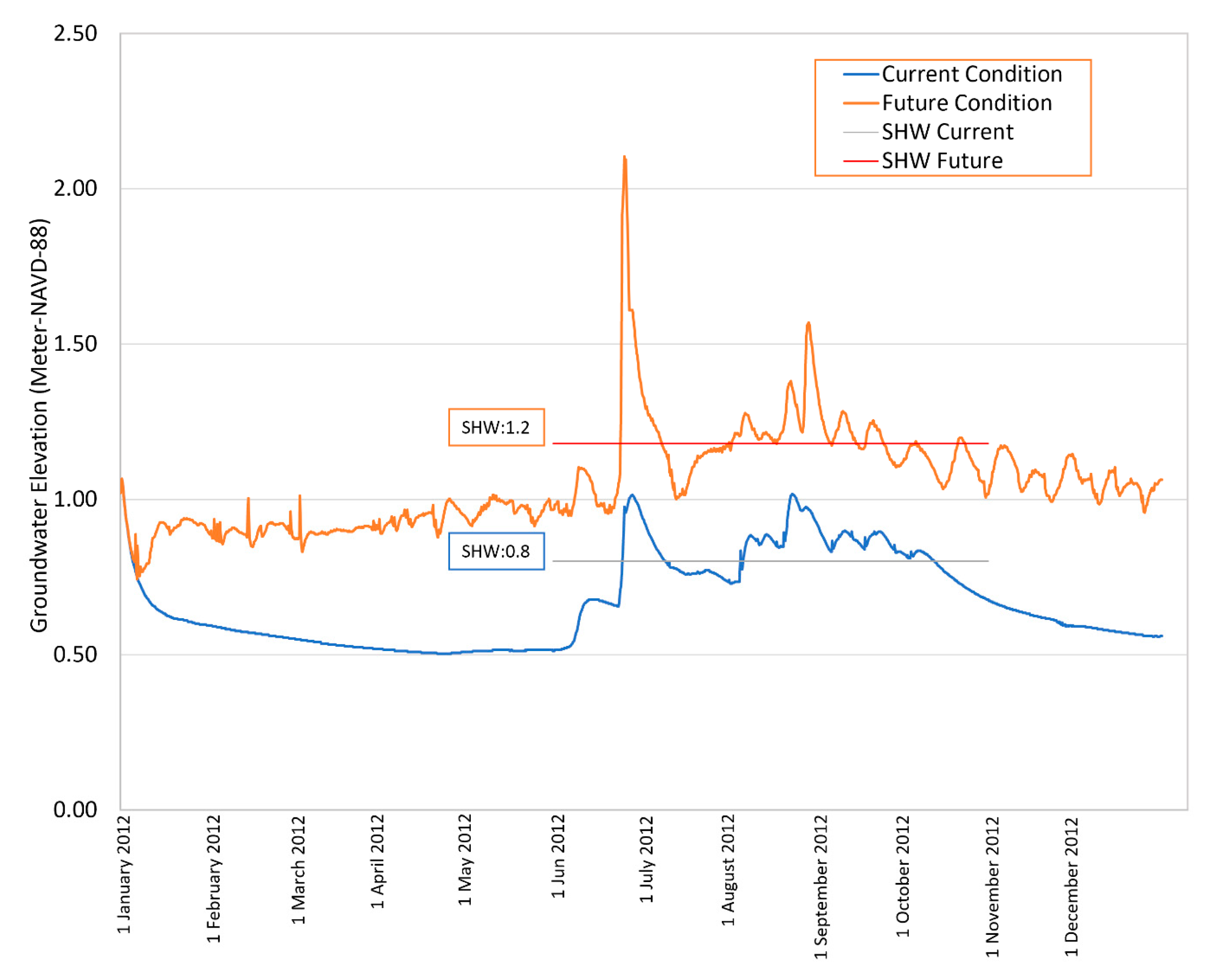
Figure 5). In addition, a boundary stage line with the same time stage data was provided for boundary conditions along tidal 2D areas of the model. For continuous simulation, the varied tide data and varied projected tide data (i.e., projected per SLR) were used for the time series boundary data under current and future conditions, respectively. For discrete events or synthetic storm simulations, a fixed value of Seasonal High Water (SHW) was used for current and future conditions at the time/stage boundary node.
4.5. Two-Dimensional Groundwater Components
The two-dimensional groundwater component of ICPR is designed to simulate horizontal flow through the surficial aquifer, vertical leakance through the confining layer, and seepage into channels, ponds, and depressions. Darcy’s law is the basis for these simulations. Like 2D surface modeling, the 2D groundwater module uses a flexible computational triangular mesh (
Figure 5). The triangles are intersected with porosity and conductivity zone polygon map layers to estimate average porosity and conductivity. Triangle nodes are intersected with different surfaces, such as the ground, confining layer, initial water table, and potentiometric elevation for extracting the required parameters. Deep percolation or leakance is allowed in ICPR and the potentiometric surface can be used to estimate gradients and amounts of leakance. Since leakance is significantly lower than horizontal and vertical conductivity, and assuming it is constant for existing and future conditions, it was not considered in the current analysis.
4.6. Impact Assessment Framework
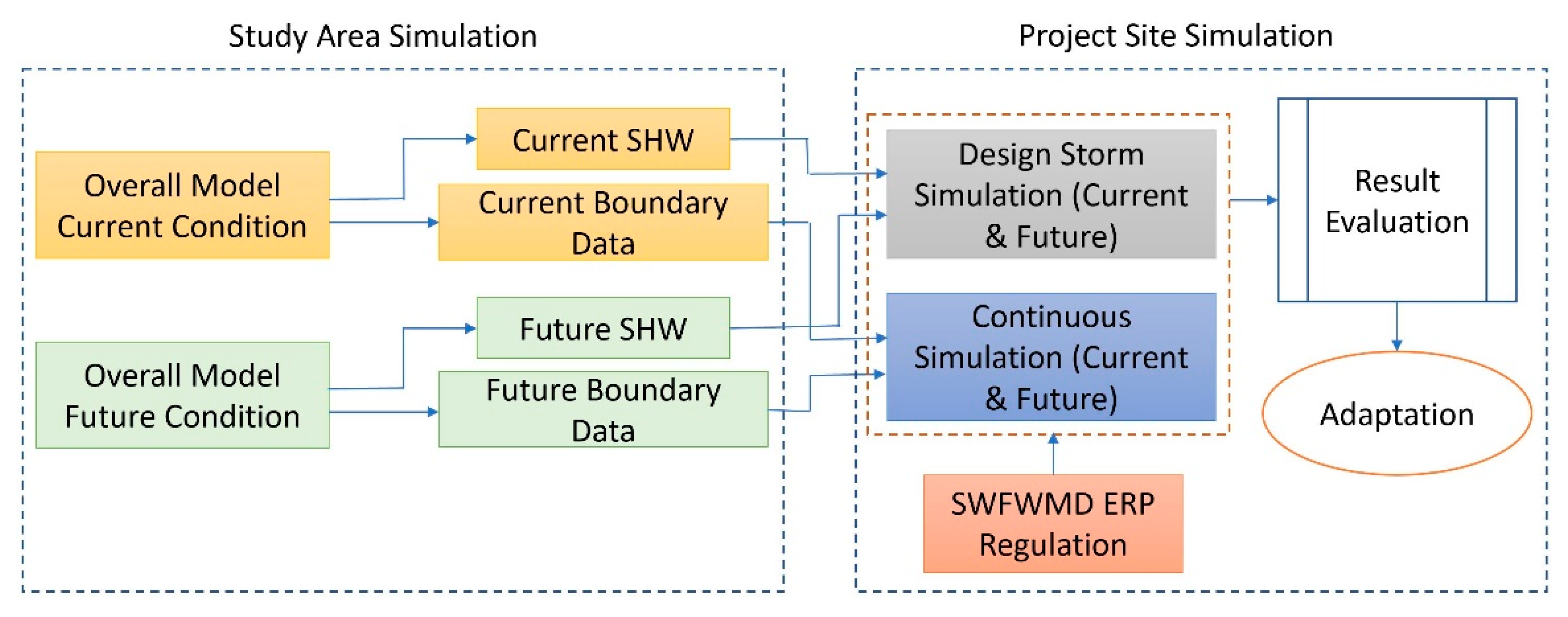
To reduce model run times, a two-stage assessment framework was applied (
Figure 6). In the first stage, the ICPR 2D surface and groundwater model was used to conduct continuous simulations for the entire study area, which contains the Tampa Bay project site. In the second stage, a reduced model domain was prepared only for the project site and a small buffer area around it. The study area was simulated under current condition, as well as future SLR-conditions with higher tailwater elevations. The smaller model domain allowed evaluation of different design options and adaptation scenarios with reasonable computational effort while using consistent boundary conditions from the study area simulation. The project site model boundary conditions provided by the continuous simulation results from the study area model, including current and future SHW levels for discrete storm simulations and surface water/groundwater time series data for continuous simulations (
Figure 6).
While the simulations included multiple years, 2012 was selected as a representative year for current conditions to provide a basis for comparing retention pond performance under different SLR and adaptation scenarios. The study area received 113 cm rainfall in 2012, which is close to the long-term average (125 cm). Likewise, the rainfall for the 2012 wet period is close to the long-term average. Tropical Storm Debby dropped about 16.5 cm of rain in the study area between 23 June and 25 June, 2012. However, even if the June rainfall were excluded from the 2012 wet period (i.e., consider July to October only), the wet period rainfall in 2012 remains close to the long term average for the July-October period (58.4 cm vs. 63.5 cm). The dry period rainfall for this year (November–May) was below the long-term average (i.e., 60 percent of the long-term average). However, the focus of this study was on the wet period, when retention ponds are most active. Thus, 2012 was deemed suitable for baseline analysis because it included an extreme event to examine the performance of the system under a wide range of hydrologic conditions.
An ICPR land use map layer was prepared to reflect post development conditions. Southwest Florida Water Management District’s ERP regulatory requirements were used to design the stormwater facility [
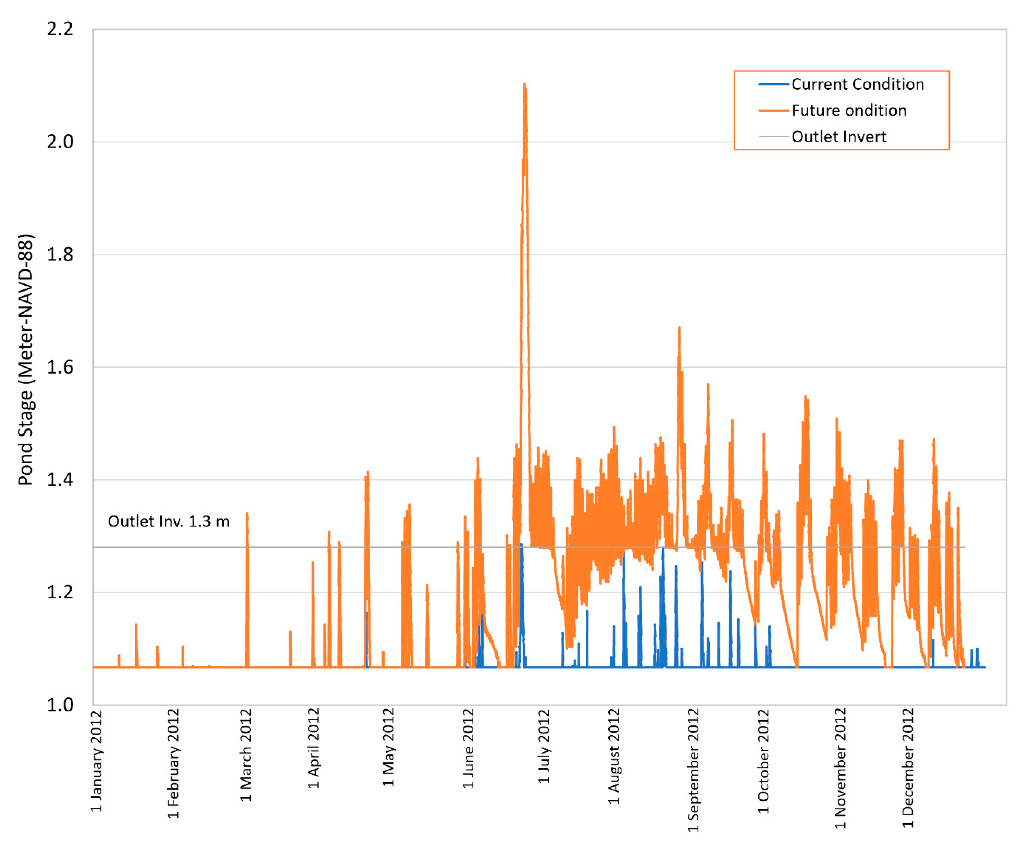
25]. The stormwater retention pond must store and percolate the first 1′ (2.54 cm) of rainfall over the site as required by SWFWMD. The total area of development (pre and post) is 3966 square meters (or 0.98 acre) and 1′ of rainfall over this area is about 101 cubic meters (or 0.082 ac-ft). Storage for this volume is to be provided by a 364 square meter retention pond with an outlet at elevation of 1.3 M-NAVD-88. The total project area consists of 1619 m
2 (0.4 ac) impervious surfaces (e.g., building, parking, and pavement) while the remaining 1983 m
2 (0.98 ac) is pervious.
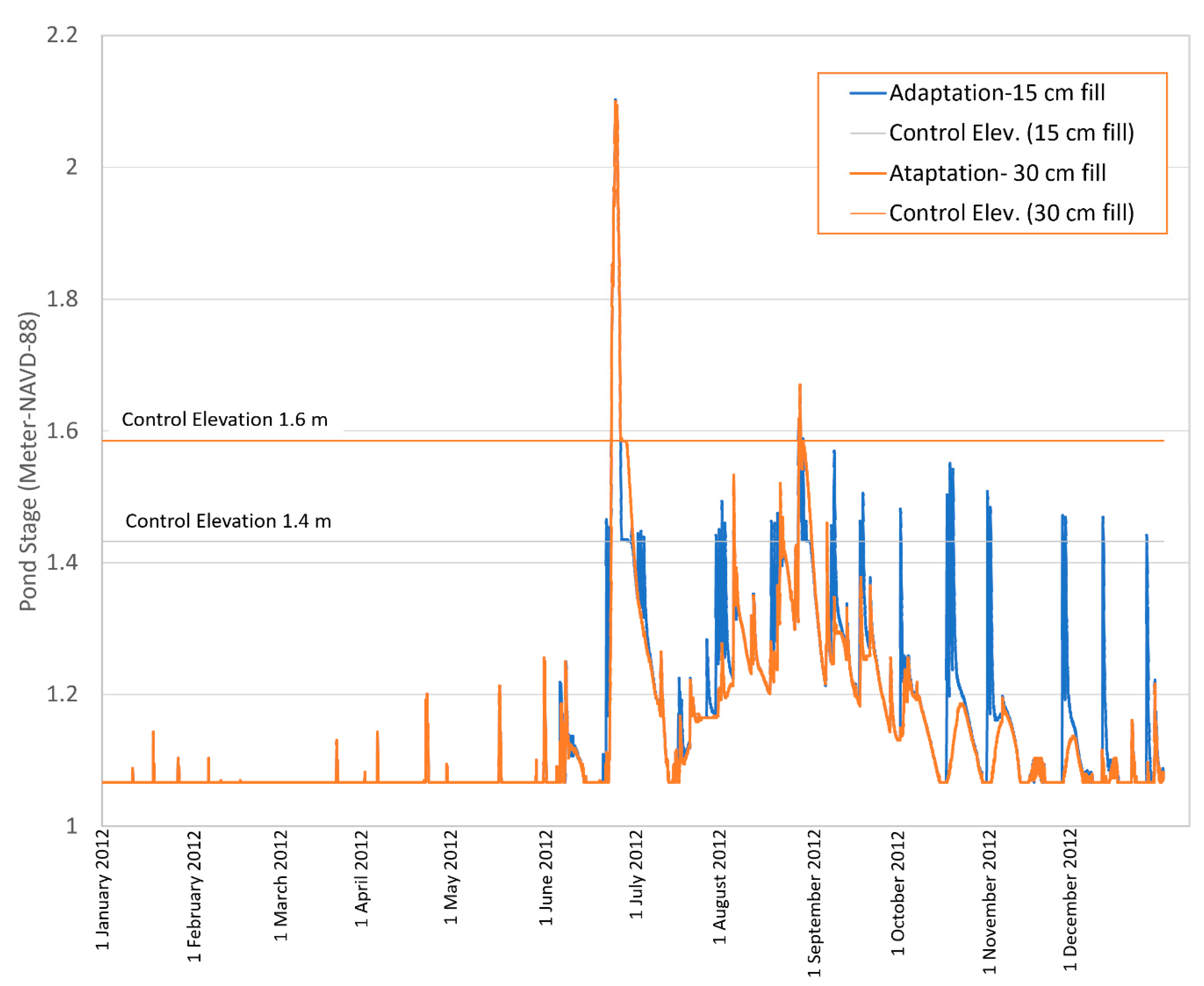
Post development hydrologic impact analysis consisted of volume recovery assessment and long-term performance of the retention basin under SLR. Based on ERP requirements, the treatment volume should be recovered within 72 h. A drawdown analysis was conducted using the small project site model for current and future conditions to ensure that the volume recovery requirement is satisfied. The project site model was also used to simulate the 25 year-24 h design storm. A year-long continuous simulation was performed to evaluate performance of the retention pond under representative current and future conditions (i.e., 2012 and 2060). For the annual design storm simulation, the tailwater and groundwater elevation were assumed to be constant and were set to current and future SHW levels as estimated from the study area simulation. For the continuous simulation, the boundary data were varied with time based on results from the study area model.
4.7. Reliability of Stormwater Retention Pond
The reliability of performance of the retention pond was evaluated using the results of the continuous simulation under current and future conditions. The reliability index defined by Hashimoto et al. [
34] has been widely used in the water resources management literature [
35,
36,
37,
38,
39]. In this study, reliability can be defined as the percentage of time that the retention pond is able to fully capture the storm runoff. In other words, any day with at least one-time outflow (regardless of duration), was defined as system failure or unmet target (Equation (7)). The ERP permitting criteria stipulates retention ponds on project sites discharging stormwater to an Outstanding Florida Water (OFW) or impaired waters, must retain more than 95% of storm events.
where
: peak stage for retention pond for day
i;
CELV: pond control elevation;
Fi flood depth above control structure for day
i; and n: number of days which is 365 in the current application.
6. Conclusions
Florida has adopted stringent requirements for environmental protection and stormwater permitting. Despite this stringent policy, the results of this case study in the Tampa Bay area show that SLR and related groundwater effects may become a significant challenge for implementing flood protection measures in low-lying coastal areas. Currently, for most of permit studies, the climate data and boundary data are assumed to be stationary with respect to SLR. The simulation results demonstrate that SLR can substantially increase groundwater elevations and decrease in the soil storage capacity. In the presented case study, this change would double the discharge volume released from stormwater pond and increase the peak flow by about 50%. Although not covered in the present analysis, stronger and more frequent recent tropical storms and hurricanes would further exacerbate the performance of stormwater retention ponds. The cumulative effects of peak flow increases reduced percolation from stormwater ponds in coastal communities can pose a significant challenge for existing primary drainage systems, which are designed for current conditions (or older). Therefore, more domestic road flooding should be expected toward the mid-century as a result of SLR-related groundwater rise alone. By the same token, under future conditions, there will be more incidents of retention ponds failing to recover treatment volumes within the required time period. These incidences will lead to release of untreated stormwater and could lead to environmental risks in the future unless plausible groundwater table rise scenarios are considered in the design and retrofit of retention ponds.
