Numerical Simulation of Flow Velocity Characteristics during Capsule Hydraulic Transportation in a Horizontal Pipe
Abstract
:1. Introduction
2. Mathematical Model
2.1. Fluid Domain Governing Equations
2.2. Solid Domain Governing Equations
2.3. Dynamic Mesh Model
2.4. Model Establishment
2.5. Mesh Division
2.6. Boundary Conditions
3. Model Validation and Result Analysis
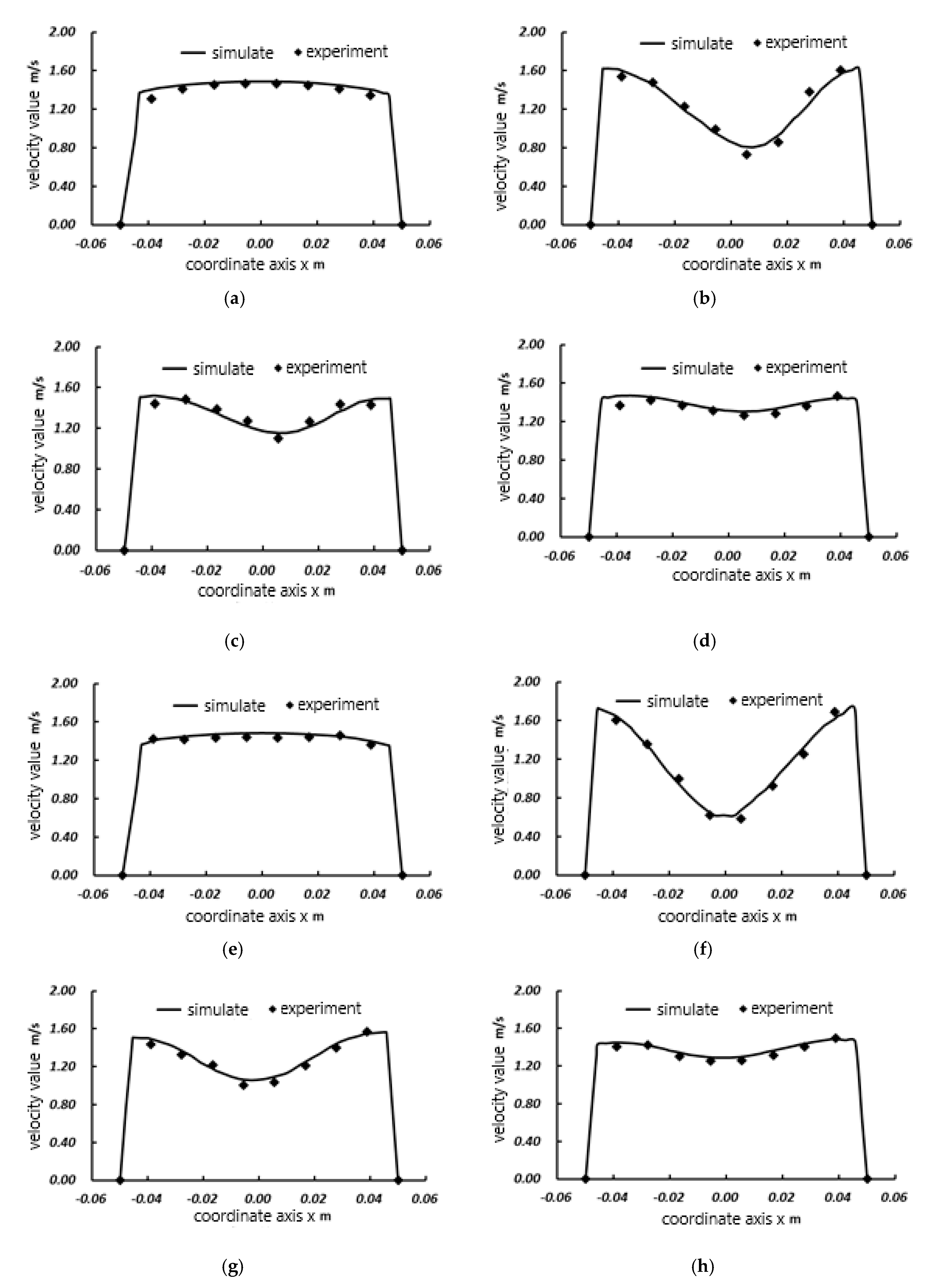
3.1. Model Validation
3.2. Result Analysis
3.2.1. Flow Velocity Characteristics of the Downstream Section of the Capsule
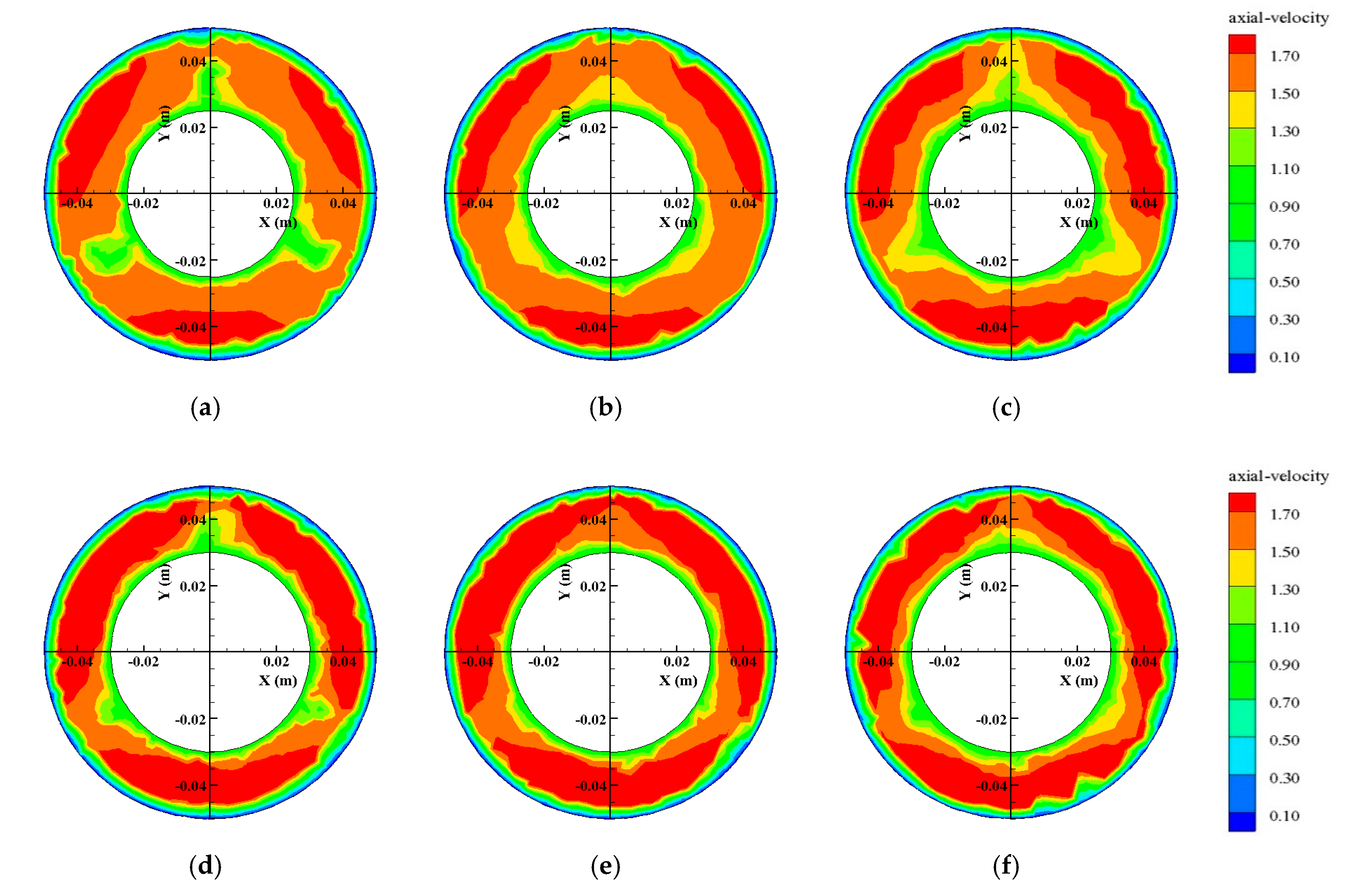
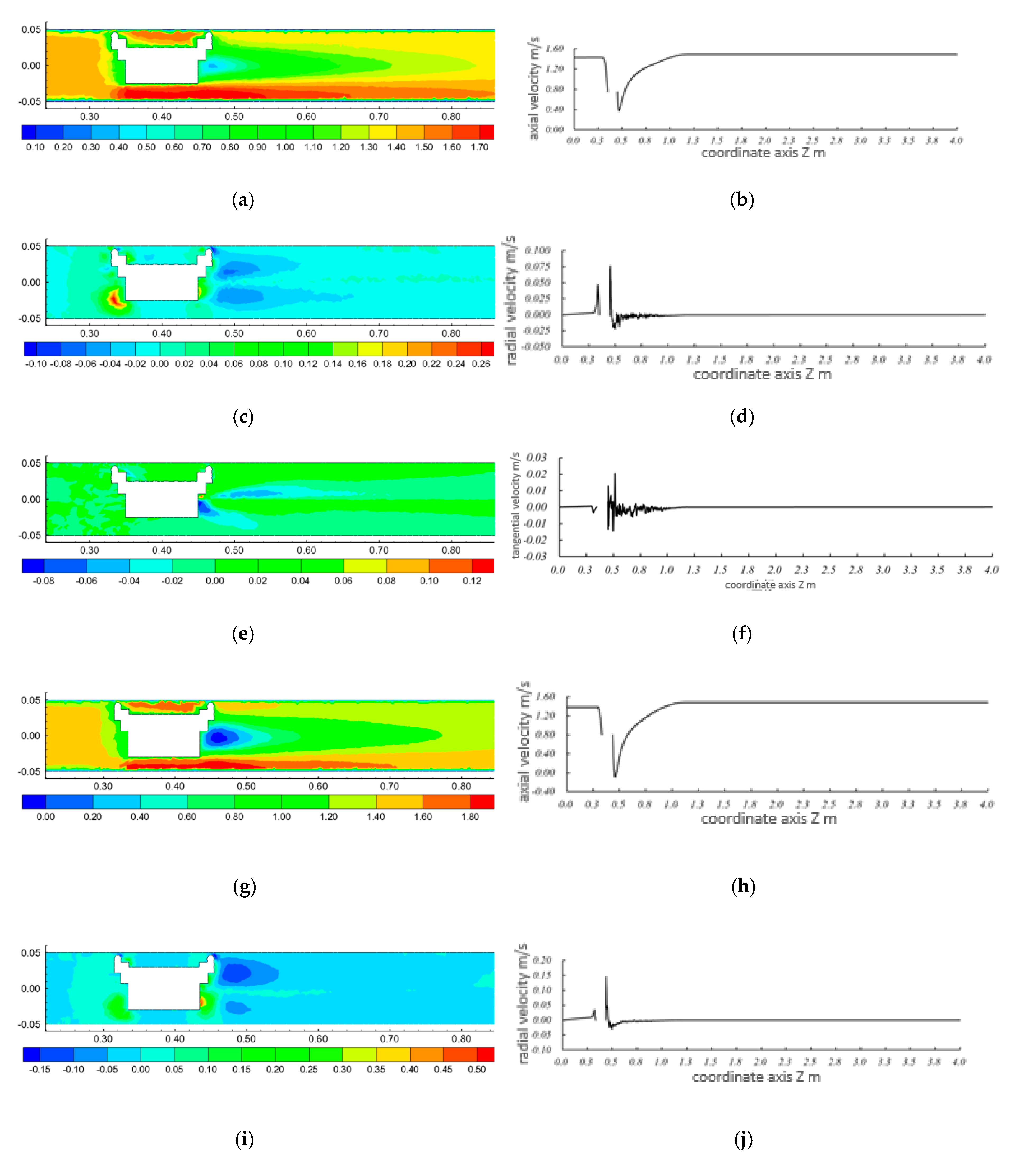
- For capsules with the same length–diameter ratio, the axial flow velocities of the downstream sections were smaller in the middle area of the pipe and larger near the inner wall of the pipe. The farther away from the downstream section of the capsule, the smaller the area of low-velocity in the middle and high-velocity in the inner wall. This was mainly because farther from the downstream section of the capsule, the velocity of the local jet formed by the annular gap flow between the capsule and the pipeline decreased in the downstream pipeline, and the flow velocity in the middle low-velocity area gradually became the flow velocity in the downstream pipeline, so the average flow velocity in the downstream section of the capsule gradually approached the average flow velocity in the pipeline. The farther from the downstream section of the capsule, the smaller the overall difference of velocity.
- For the same downstream section of the capsule, the axial flow velocity of the same location increased with the increased length–diameter ratio of the capsule. Moreover, the area of low-flow velocity in the downstream section of the capsule was greatly affected by the length–diameter ratio. As for the two capsules in this paper, the larger the capsule’s length–diameter ratio, the smaller the influence range of the low-flow velocity area. This was mainly related to the generation of the low-velocity region and the local jet formed by annular gap flow. The greater the length–diameter ratio of the capsule, the greater the local jet area formed between the capsule and the pipe, and the smaller the cavity area formed downstream of the capsule, resulting in a decreased area of downstream flow randomly filling the mainstream cavity area.
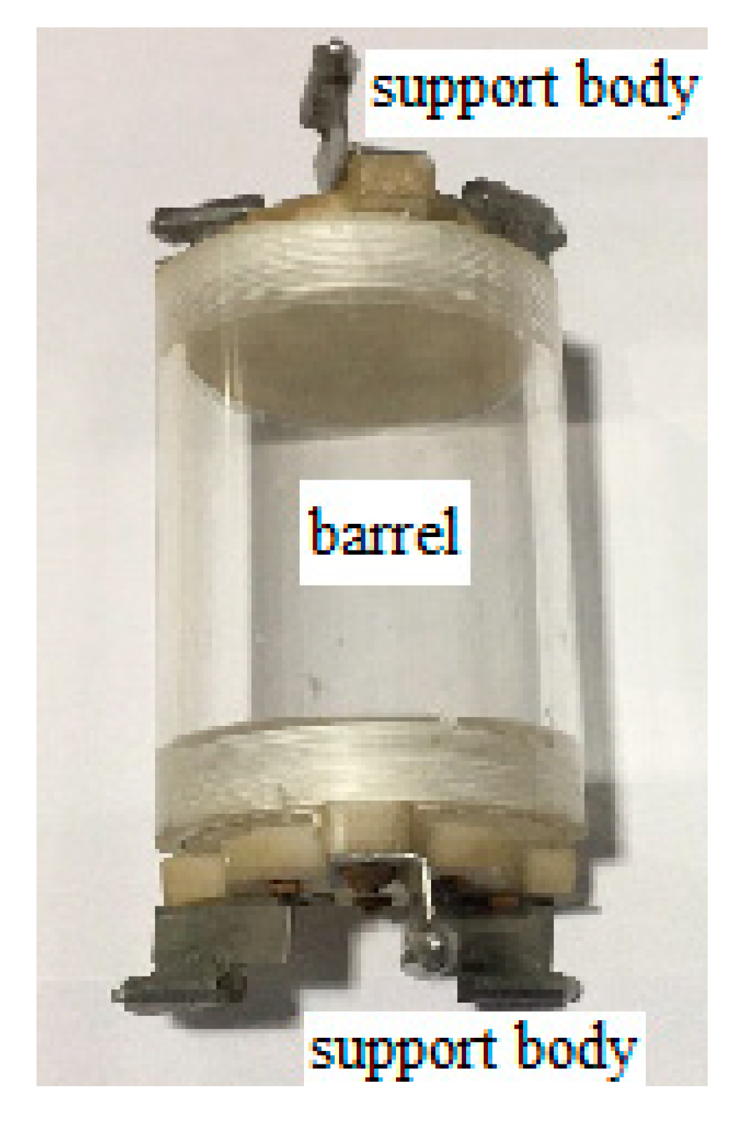
- The flow velocity distribution in the downstream section of the capsule was greatly affected by the support body of the capsule section. Since the front and rear faces of the capsule were installed with cylindrical supports at equal interval angles of 120°, the high-velocity area was divided into three central symmetrical areas.
- For the same flow discharge condition, the variation of radial flow velocity in the downstream section of the capsule with different length–diameter ratios was basically the same, and the radial velocity from the inner wall of the pipe to the center of the pipe showed a changing trend of first increasing and then decreasing. At the same time, the annular gap flow caused a local cavity in the center of the pipeline, and the radial velocity was small, while there was no deformation near the wall boundary, and the streamline did not change greatly. For the annular region in the middle of the pipe, the sudden expansion of the streamline caused the flow to jet into the center of the pipe, which resulted in the larger radial velocity of the annular region in the middle compared with other regions. Moreover, the radial flow velocity of the annular region in the middle was basically negative, indicating that the flow direction along the radial direction was from the inner wall to the center of the pipe.
- For the same downstream section of the capsule, the radial flow velocity at the same location increased with an increased length–diameter ratio of the capsule. This was mainly because the radial flow velocity of the downstream section was related to the convergence of the annular gap flow to the downstream pipeline. The larger the length–diameter ratio, the larger the volume of the downstream cavity formed between the capsule and the pipe, the greater the convergence degree of the annular gap flow, and the larger the radial flow velocity.
- Farther from the downstream section of the capsule, the kinetic energy generated by the annular gap flow formed between the capsule and the pipeline decreased gradually, and the interaction between the annular gap flow and the flow in the downstream pipeline resulted in the inconsistency of the radial flow velocity distribution in the downstream section.
- For the same flow conditions, the changing trend of circumferential flow velocity in the downstream section of the capsule with different length–diameter ratios was basically the same, which was mainly distributed around the support body of the capsule. Moreover, at the left and right positions of the support body, the circumferential flow velocity presented the symmetrical distribution law in the opposite direction. At the same time, the farther from the downstream section of the capsule, the smaller the tangential velocity of the downstream section.
- For the same downstream section of the capsule, the circumferential flow velocity at the same location increased with an increased length–diameter ratio of the capsule. The main reason was that the circumferential velocity of the downstream section was related to the influence degree of the annular gap flow around the support body of the capsule. The larger the length–diameter ratio, the greater the influence of the annular gap flow around the support body of the capsule, and the greater the circumferential flow velocity.
3.2.2. Flow Velocity Characteristics of the Upstream Section of the Capsule
- For the same section upstream of the capsule, the smaller the length–diameter ratio of the capsule, the smaller the axial flow velocity at the same location. The main reason was that the axial flow velocity in the upstream section was related to the length–diameter ratio. The smaller the length–diameter ratio of the capsule, the larger the action area blocking the axial movement, and the more significant the effect of decreasing the axial velocity. The influence of the capsule on the axial flow velocity in the upstream section was small and only located in the area near the wall of the upstream section.
- The flow velocity distribution in the upstream section of the capsule was greatly affected by the support body of the capsule section. Since the front and rear faces of the capsule were installed with cylindrical supports at equal interval angles of 120°, the axial flow velocity was divided into three central symmetrical areas, and the low-flow velocity region was located at the support body position of the capsule. The main reason was that when water flowed around the cylindrical support body, a local circumfluence phenomenon occurred, which reduced the kinetic energy of the flow and increased the pressure energy so that a low-velocity zone appeared at the position of the support body of the capsule. However, the area of the low-flow velocity region caused by the support body of the capsule was basically the same.
- Under the same flow discharge condition, the larger the length–diameter ratio of the capsule, the smaller the influence distance of the capsule on the upstream flow. The main reason was the existence of the capsule, which made the flow in the pipeline fluctuate greatly when passing through the capsule. Moreover, the larger the length–diameter ratio, the smaller the influence range of the wave on the water flow, and the smaller the influence distance on the flow in the upstream section of the capsule.
- For the same flow discharge conditions, the variation trend of radial flow velocity in the upstream section of the capsule with different length–diameter ratios was basically the same. On the whole, the radial flow velocity from the inner wall to the center of the pipe first increased and then decreased. The radial flow velocity in the area of the center and the inner wall of the pipe was basically zero.
- The cylindrical support body was installed at the front and rear faces of the capsule at equal interval angles of 120°. The radial flow velocity distribution area was divided into three regions with basically equal areas for the influence of the cylindrical support body, and the smaller the length–diameter ratio of the capsule, the larger the distribution area of radial velocity.
- Under the same flow conditions, the larger the length–diameter ratio of the capsule, the shorter the influence range of the radial flow velocity of the upstream section of the capsule. At the same time, regardless of the transporting condition of the capsule, the farther from the upstream section of the capsule, the smaller the radial velocity of the upstream section of the capsule.
- Under the same transportation conditions, the area of the radial low-flow velocity area in the center of the pipeline increased with the increased length–diameter ratio of the capsule. The main reason was that the flow distance of the fluid group in the upstream section of the capsule became longer for the length–diameter ratio and the interaction between the front and back fluid groups became more obvious, thus the obvious radial movement was formed.
- For the same section upstream of the capsule, the radial flow velocity at the same location was positively correlated with the length–diameter ratio of the capsule; that is, the radial flow velocity decreased with the decreased length–diameter ratio.
- The changing trend of circumferential velocity in the upstream section of the capsule with different length–diameter ratios was basically the same as that in the downstream section, which was mainly distributed around the support body of the capsule, showing a symmetrical distribution. Moreover, the circumferential flow velocity around the support body decreased with the decreased length–diameter ratio. At the same time, the farther from the upstream section of the capsule, the smaller the circumferential velocity of the upstream section of the capsule.
- For the same upstream section of the capsule, the circumferential flow velocity of the same location increased with the increased length–diameter ratio of the capsule. The main reason was that the circumferential flow velocity distribution of the upstream section was related to the flow around the capsule and the support body, and its value was determined by the flow velocity in the pipeline and the movement velocity of the capsule. As the length–diameter ratio decreased, the movement velocity of the capsule increased, and the difference between the velocity of the capsule and the flow velocity in the pipeline became smaller and smaller. Therefore, the circumferential flow velocity at the same position of the upstream section of the capsule decreased gradually with the decreased length–diameter ratio.
3.2.3. Axial Flow Velocity Characteristics of Annular Gap Section between Capsule and Pipe
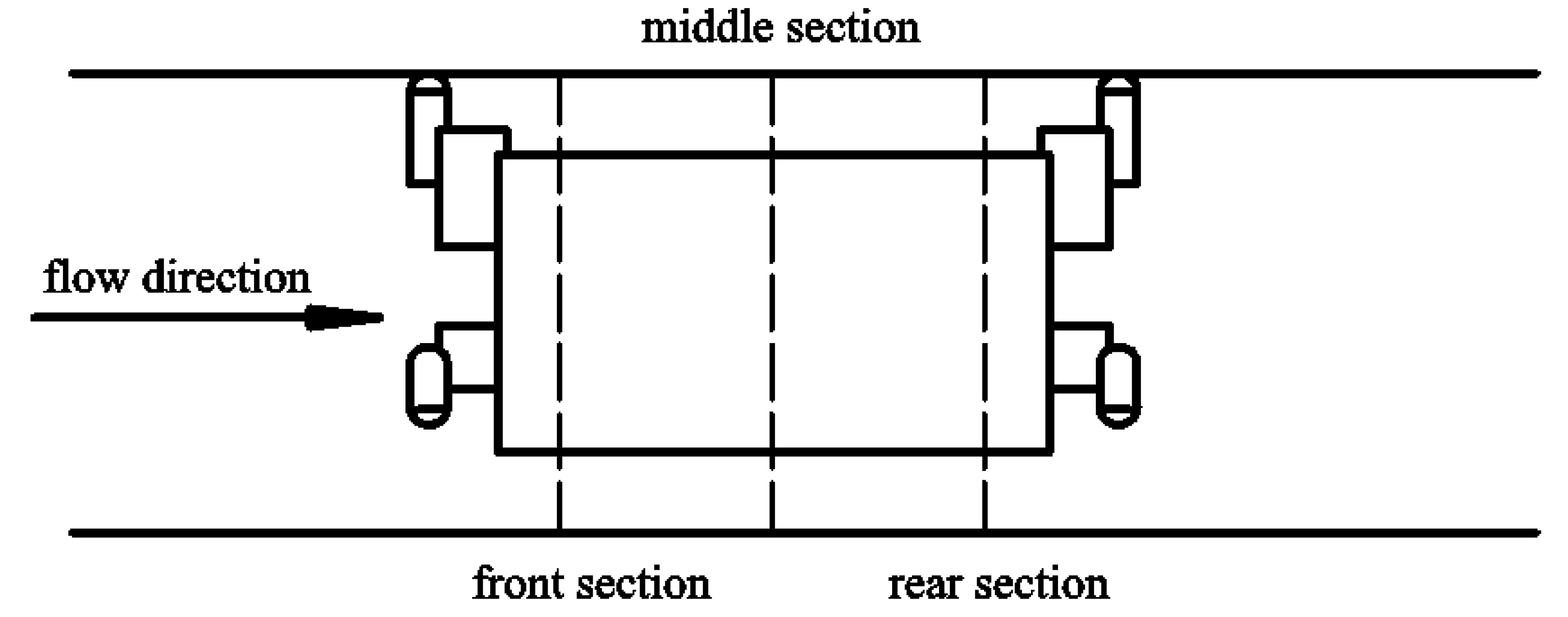
- Under the same transportation conditions, the axial flow velocity in the front, middle, and rear annular gap sections of the capsule first increased and then decreased from the inner wall of the pipe to the outer wall of the capsule. However, for the same section, the axial velocity of the annular gap flow in the rear section of the capsule decreased faster, while that in the front section decreased slower.
- The thickness of the boundary layer formed by the dynamic boundary was obviously smaller than that of the static boundary layer during the material transport of the capsule. The main reason was that the inner wall of the pipeline belonged to the static boundary. Under the action of the viscous force of flow, a stable boundary layer thickness in the inner wall of the pipeline could be formed. However, for the moving capsule, its wall was the dynamic boundary. Relative motion occurred between the fluids at different velocity layers in the moving boundary region, and the viscous force of flow could not act stably on the fluid groups in each layer, resulting in the relatively small dynamic boundary layer thickness.
3.2.4. Distribution of Flow Field and its Influence Range during Movement of the Capsule
- In the process of transporting materials, the capsule had a small influence on the upstream flow field but a large influence on the downstream flow field. The main reason was that the flow velocity in the pipeline was higher than that of the capsule, which caused local flow around the inside of the fluid. The annular gap flow caused cavities of different sizes in the downstream flow field area of the capsule. The flow in the downstream area of the capsule would randomly fill the region. Under the interaction between the capsule and the flow in the downstream pipeline, the flow velocity of the cavity region was low. However, the flow velocity in the downstream region of the capsule would eventually return to the state of flow velocity when the capsule was not released. Therefore, in the process of conveying materials, the flow field in the downstream region was greatly affected by the capsule.
- In the process of conveying materials, there was a local axial low-velocity region in the downstream section of the capsule, and the area of this region increased with the increased length–diameter ratio of the capsule.
- In the process of conveying materials, the radial velocity of the upstream and downstream section near-wall region was larger, and there were two larger areas of radial velocity distribution in the downstream section near-wall region; the radial velocity of the two regions was the same, and the direction was opposite.
- In the process of transporting materials, the circumferential flow velocity in the pipeline was mainly distributed around the support body in the front and rear sections of the capsule. Moreover, the circumferential flow velocity of the front section of the capsule propagated continuously downstream.
- In the process of transporting materials, the axial flow velocity at the center of the pipe first decreased and then increased. In the front section of the capsule, the axial flow velocity reached the minimum value. The distribution trends of the circumferential and radial velocity of the flow at the center of the pipeline were basically the same; that is, they were lower at the upstream section of the capsule, while downstream of the capsule they first fluctuated greatly, then gradually decreased, and finally approached zero.
4. Conclusions
- The variation trend of axial flow velocity in the downstream section of the capsule was basically the same, which was smaller in the middle area of the pipeline and larger near the inner wall. The radial flow velocity first increased and then decreased from the inner wall to the center of the pipe. The circumferential flow velocity was distributed near the support body of the capsule. At the left and right of the support body, the direction of the circumferential velocity was opposite, showing a symmetrical distribution. Moreover, the axial velocity, radial velocity, and circumferential flow velocity all increased with the increased length–diameter ratio of the capsule.
- The influence of the capsule on the axial velocity of the flow in the upstream section was small, only in the area near the wall of the upstream section of the capsule. The radial flow velocity first increased and then decreased from the inner wall to the center of the pipe, and the radial flow velocity in the center and the inner wall of the pipe was basically zero. The circumferential flow velocity was distributed around the support body of the capsule, showing a symmetrical distribution. Moreover, the axial velocity, radial velocity, and circumferential velocity all increased with the increased length–diameter ratio of the capsule.
- The axial flow velocity in the front, middle, and rear annular gap sections of the capsule first increased and then decreased from the inner wall of the pipe to the outer wall of the capsule. The axial velocity of the annular gap flow was positively correlated with the length–diameter ratio of the capsule.
- In the process of transporting materials, the capsule had a small influence on the upstream flow field area but a large influence on the downstream flow field area.
Author Contributions
Funding
Acknowledgments
Conflicts of Interest
Data Availability
References
- Chai, J.; Xing, L.M.; Zhou, Y.H.; Wei, B.L.; Wang, S.Y. Effect of Transportation Structure Change on CO2 Emission. Opera. Res. Mgt. Sci. 2017, 26, 110–116. [Google Scholar]
- Singh, M.K.; Kumar, S.; Ratha, D.; Kaur, H. Design of slurry transportation pipeline for the flow of muti-particulate coal ash suspension. Int. J. Hydrogen Energy 2017, 42, 19135–19138. [Google Scholar] [CrossRef]
- Liu, H.; Marrero, T.R. Coal log pipeline Technology: An overview. Powder Technol. 1997, 94, 217–222. [Google Scholar] [CrossRef]
- Yang, X.; Ma, J. The wall stress of the capsule surface in the straight pipe. Water 2020, 12, 242. [Google Scholar] [CrossRef] [Green Version]
- Faghihifard, M.; Badri, M.A. Simulation of oil pollution in the Persian Gulf near Assaluyeh oil terminal. Mar. Pollut. Bull. 2016, 105, 143–149. [Google Scholar] [CrossRef]
- Xie, S.H.; Cai, H.Y.; Xia, G.X. Calculation of the carbon emissions of Chinese transportation industry and the driving factors. J. Arid Land Resour. Environ. 2016, 30, 13–18. [Google Scholar]
- Sahith, S.J.K.; Rao, K.V.; Rao, P.S. Design and surge study of Salaya Mathura pipeline for higher throughput of crude oil transportation. Mater. Today Proc. 2018, 5, 5459–5466. [Google Scholar] [CrossRef]
- Asim, T.; Mishra, R. Computational fluid dynamics based optimal design of hydraulic capsule pipelines transporting cylindrical capsules. Powder Technol. 2016, 295, 180–201. [Google Scholar] [CrossRef] [Green Version]
- Brandoni, C.; Marchetti, B.; Ciriachi, G.; Polonara, F.; Leporini, M. The impact of renewable energy systems on local sustainability. Int. J. Product. Qual. Manag. 2016, 18, 385–402. [Google Scholar] [CrossRef]
- Khalil, M.F.; Kassab, S.Z.; Adam, I.G.; Samaha, M.A. Turbulent flow around single concentric long capsule in a pipe. Appl. Math. Model. 2010, 34, 2000–2017. [Google Scholar] [CrossRef] [Green Version]
- Turkowski, M.; Szudarek, M. Pipeline system for transporting consumer goods, parcels and mail in capsules. Tunn. Undergr. Space Technol. 2019, 93, 103057. [Google Scholar] [CrossRef]
- Leporini, M.; Terenzi, A.; Marchetti, B.; Corvaro, F.; Polonara, F. On the numerical simulation of sand transport in liquid and multiphase pipelines. J. Petrol. Sci. Eng. 2018, 175, 519–535. [Google Scholar] [CrossRef]
- Rawat, A.; Singh, S.N.; Seshadri, V. Erosion wear studies on high concentration fly ash slurries. Wear 2017, 378, 114–125. [Google Scholar] [CrossRef]
- Liu, H. Feasibility of Using Pneumatic Capsule Pipelines in New York City for Underground Freight Transport. In Proceedings of the ASCE Pipeline Conference, San Diego, CA, USA, 1–4 August 2004. [Google Scholar]
- Bagegni, A.; Adams, G.; Hoft, R. Tubular linear induction hydraulic capsule pipeline. I. Finite element analysis. IEEE Trans. Energy Convers. 1993, 8, 251–256. [Google Scholar] [CrossRef]
- Ulusarslan, D. Determination of the loss coefficient of elbows in the flow of low-density spherical capsule train. Exp. Therm. Fluid Sci. 2007, 32, 415–422. [Google Scholar] [CrossRef]
- Kollár, L.E.; Mishra, R.; Asim, T. Particle Size Effects on Optimal Sizing and Lifetime of Pipelines Transporting Multi-sized Solid-Liquid Mixtures. Procedia CIRP 2013, 11, 317–322. [Google Scholar]
- Agarwal, V.; Singh, M.; Mathur, R. Empirical relation for the effect of the shape of the capsule and the nose shape on the velocity ratio of heavy density capsules in a hydraulic pipeline. Proc. Inst. Mech. Eng. Part E J. Process Mech. Eng. 2001, 215, 147–155. [Google Scholar] [CrossRef]
- Agarwal, V.C.; Mishra, R.; Swamee, P.K. Discussion and Closure: Design of Pipelines to Transport Neutrally BuoyantCapsules. J. Hydraul. Eng. 2000, 126, 91–93. [Google Scholar] [CrossRef]
- Agarwal, V.C.; Mishra, R. Optimal design of a multi-stage capsule handling multi-phase pipeline. Int. J. Press. Vessel. Pip. 1998, 75, 27–35. [Google Scholar] [CrossRef]
- Li, Y.Y.; Sun, X.H.; Zhang, X.L. Experimental study of the wheeled capsule motion inside hydraulic pipeline. Adv. Mech. Eng. 2019, 11, 1–11. [Google Scholar] [CrossRef]
- Li, Y.Y.; Sun, X.H. Mathematical model of the piped vehicle motion in piped hydrotransport of tube-contained raw material. Math. Probl. Eng. 2019, 2, 1–10. [Google Scholar]
- Li, Y.Y.; Sun, X.H.; Zhang, X.L. Study of the energy consumption of the piped vehicle hydrotransport. Adv. Mech. Eng. 2019, 11, 1–12. [Google Scholar]
- Ulusarslan, D.; Teke, I. Comparison of pressure gradient correlations for the spherical capsule train flow. Particul. Sci. Technol. 2008, 26, 285–295. [Google Scholar] [CrossRef]
- Ulusarslan, D.; Teke, I. An experimental investigation of the capsule velocity, concentration rate and the spacing between the capsules for spherical capsule train flow in a horizontal circular pipe. Powder Technol. 2005, 159, 27–34. [Google Scholar] [CrossRef]
- Ginevskii, A.S.; Kolesnikov, A.V. Theory of the motion of rafts on a river and capsules in a pipeline. Prandtl’s paradox. Fluid Dyn. 1980, 15, 864–872. [Google Scholar] [CrossRef]
- Ooms, G.; Pourquie, M.J.B.M.; Beerens, J.C. On the levitation force in horizontal core-annular flow with a large viscosity ratio and small density ratio. Phys. Fluids 2013, 25, 1–16. [Google Scholar] [CrossRef]
- Sotgia, G.; Tartarini, P.; Stalio, E. Experimental analysis of flow regimes and pressure drop reduction in oil-water mixtures. Int. J. Multiph. Flow 2008, 34, 1161–1174. [Google Scholar] [CrossRef]
- Lee, B.; Kang, M. Full 3D simluations of two-phase core-annular flow in horizontal pipe using level set method. J. Sci. Comput. 2016, 34, 1025–1051. [Google Scholar] [CrossRef]
- Jing, Y.H.; Guo, X.H.; Sun, X.H.; Li, Y.Y. Hydraulic characteristics of cyclical slit flow for piped carriage. Water Resour. Power 2014, 32, 151–155. [Google Scholar]
- Zhang, X.L.; Sun, X.H.; Li, Y.Y. Pressure characteristics of flow induced by moving cylindrical capsules in hydraulic capsule transportation. J. Drain. Irrig. Mach. Eng. 2014, 32, 231–234. [Google Scholar]
- Zhang, C.J.; Sun, X.H.; Li, Y.Y.; Zhang, X.Q. Numerical simulation of hydraulic characteristics of cyclical slit flow with moving boundary of tube-contained raw materials pipelines hydrotransport. Trans. Chin. Soc. Agric. Eng. 2017, 33, 76–85. [Google Scholar]
- Zhang, C.J.; Sun, X.H.; Li, Y.Y.; Zhang, X.Q.; Zhang, X.L.; Yang, X.N.; Li, F. Effects of guide vane placement angle on hydraulic characteristics of flow field and optimal design of hydraulic capsule pipelines. Water 2018, 10, 1378. [Google Scholar] [CrossRef] [Green Version]
- Wang, Z.X.; Zhang, L.R.; He, L.L.; Wang, J.W.; Hu, Y.J. Analysis on output power of horizontal axis wind turbine based on two-way fluid-structure interaction. J. Drain. Irrig. Mach. Eng. 2017, 35, 975–980. [Google Scholar]
- Yang, X.N.; Ma, J.J.; Li, Y.Y.; Sun, X.H.; Jia, X.M.; Li, Y.G. Wall stresses in cylinder of stationary piped carriage using COMSOL multiphysics. Water 2019, 11, 1910. [Google Scholar] [CrossRef] [Green Version]
- Li, Y.Y.; Sun, X.H.; Li, F. Hydraulic characteristics of transportation of different piped carriages in pipe. J. Drain. Irrig. Mach. Eng. 2010, 28, 174–178. [Google Scholar]
- Tong, X.W.; Li, Y.Y.; Sun, X.H. Experimental system design on the piped hydrotransport of tube-contained raw material. Shanxi Water Resour. 2008, 2, 42–43. [Google Scholar]
- Joseph, D.D.; Renardy, Y.Y. Fundamentals of Two-Fluid Dynamics; Springer: New York, NY, USA, 1993. [Google Scholar]
- Wu, C.G. Hydraulics; Higher Education Press: Beijing, China, 2003. [Google Scholar]






| A | (0, 0.05, 0) | B | (0, −0.05, 0) | C | (0, −0.05, 11.0) |
| D | (0, 0.05, 11.0) | E | (0, 0, 0.3) |
| Volume Mesh Size | Grid Cell | Velocity at the Coordinate (0, 0, 1) | ||
|---|---|---|---|---|
| Vx (m/s) | Vy (m/s) | Vz (m/s) | ||
| 0.008 m | 1514464 | 0.000161284 | −0.0036124 | 1.49384 |
| 0.007 m | 1942178 | 0.000081247 | −0.0019522 | 1.47659 |
| 0.006 m | 2514769 | 0.000042387 | −0.0013584 | 1.46554 |
| 0.005 m | 3238411 | 0.000039584 | −0.0006253 | 1.45831 |
| 0.004 m | 3745843 | 0.000024927 | −0.0004855 | 1.45623 |
| 0.003 m | 4319562 | 0.000024315 | −0.0002516 | 1.45447 |
| 0.002 m | 5684124 | 0.000024113 | −0.0002436 | 1.45433 |
| 0.001 m | 9268415 | 0.000024132 | −0.0002411 | 1.45431 |
© 2020 by the authors. Licensee MDPI, Basel, Switzerland. This article is an open access article distributed under the terms and conditions of the Creative Commons Attribution (CC BY) license (http://creativecommons.org/licenses/by/4.0/).
Share and Cite
Li, F.; Li, Y.; Sun, X.; Yang, X. Numerical Simulation of Flow Velocity Characteristics during Capsule Hydraulic Transportation in a Horizontal Pipe. Water 2020, 12, 1015. https://doi.org/10.3390/w12041015
Li F, Li Y, Sun X, Yang X. Numerical Simulation of Flow Velocity Characteristics during Capsule Hydraulic Transportation in a Horizontal Pipe. Water. 2020; 12(4):1015. https://doi.org/10.3390/w12041015
Chicago/Turabian StyleLi, Fei, Yongye Li, Xihuan Sun, and Xiaoni Yang. 2020. "Numerical Simulation of Flow Velocity Characteristics during Capsule Hydraulic Transportation in a Horizontal Pipe" Water 12, no. 4: 1015. https://doi.org/10.3390/w12041015
APA StyleLi, F., Li, Y., Sun, X., & Yang, X. (2020). Numerical Simulation of Flow Velocity Characteristics during Capsule Hydraulic Transportation in a Horizontal Pipe. Water, 12(4), 1015. https://doi.org/10.3390/w12041015


