Holistic Design Approach of a Throttled Surge Tank: The Case of Refurbishment of Gondo High-Head Power Plant in Switzerland


Abstract
1. Introduction

| Goal | Physical Scale | 1D Numerical Simulation | 3D Numerical Simulation (CFD) | Prototype Validation | Source |
|---|---|---|---|---|---|
| Geometry optimization and flow visualization | Done | Not done | Done | Not done | [16] |
| Throttle optimization | Not done | Done | Not done | Not done | [17] |
| Throttle optimization | Not done | Not done | Done | Not done | [18] |
| Throttle optimization | Not done | Done | Not done | Not done | [19] |
| Flow visualization | Done | Not presented | Done | Not done | [12] |
| Geometry optimization and flow visualization | Done | Not done | Done | Not done | [13] |
| Geometry optimization | Done | Done | Not done | Not done | [9] |
| Geometry optimization | Done | Done | Not done | Not done | [3] |
| Geometry optimization and flow visualization | Done | Done | Done | Not done | [6] |
| Geometry optimization and flow visualization | Done | Not done | Done | Not done | [20] |
| Geometry optimization and flow visualization | Done | Not done | Done | Not done | [21] |
| Geometry optimization | Not done | Done | Not done | Not done | [22] |
| Geometry optimization and flow visualization | Done | Done | Done | Not done | [15] |
| Geometry optimization and flow visualization | Done | Done | Done | Done | Current study |
2. Materials and Methods
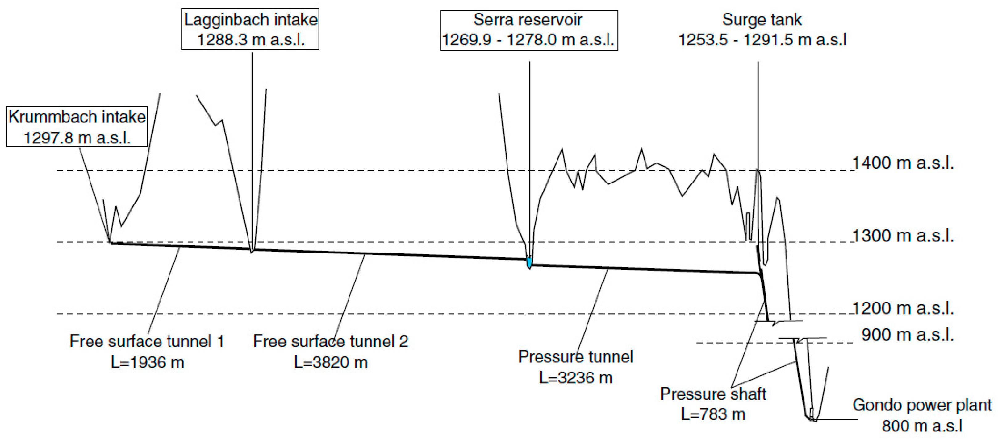
2.1. Case Study Summary
- Increase of the existing injectors closure time to fulfill admissible maximum pressure in the penstock (load case: peak of Michaud)
- A solution is found to prevent surge tank dewatering (load case: unloading followed by a unit reloading)
2.2. CFD Model
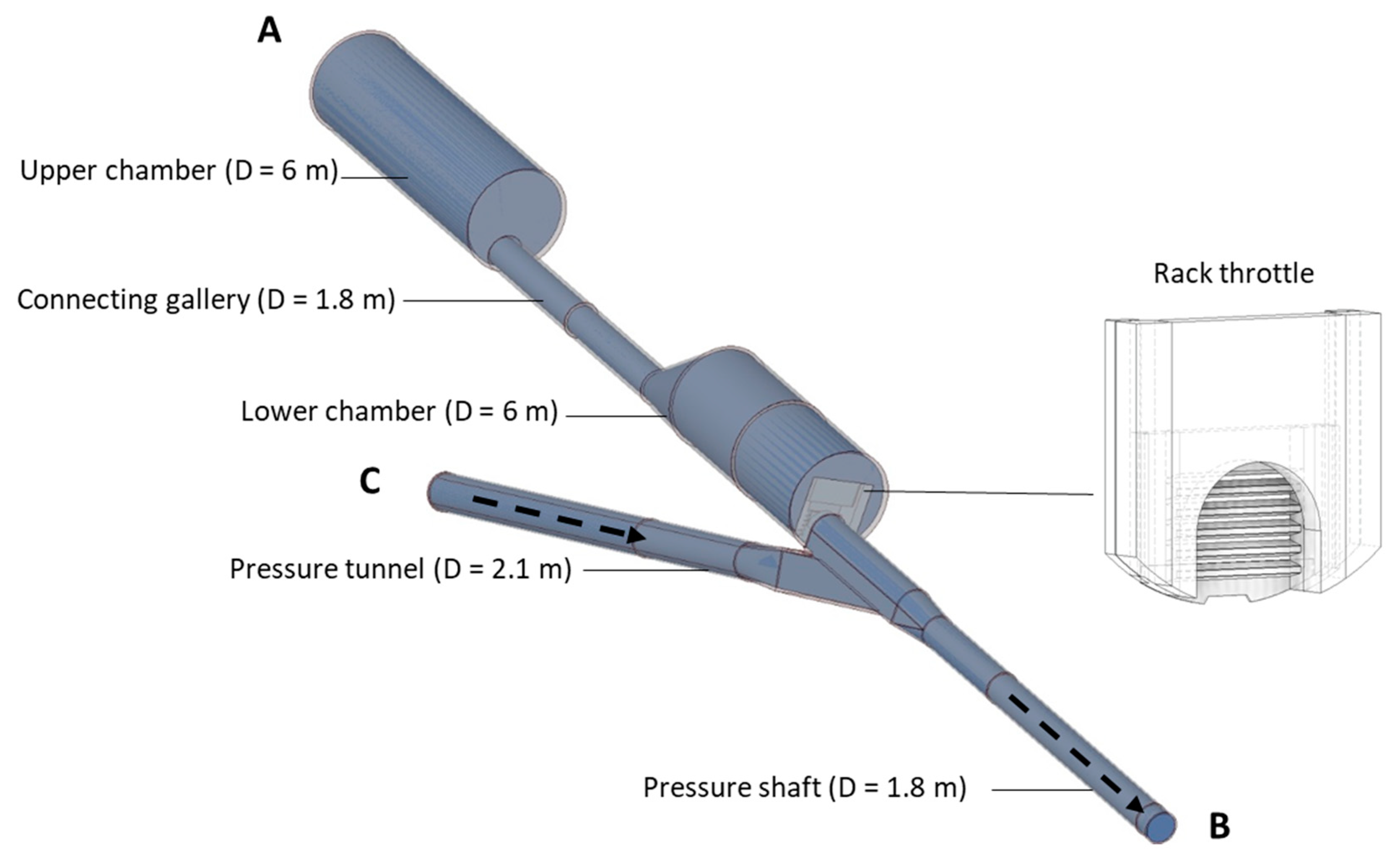
2.2.1. Geometry and Meshing
2.2.2. Pre-Processing: Physical Parameters, Boundary Conditions, and Turbulence Model
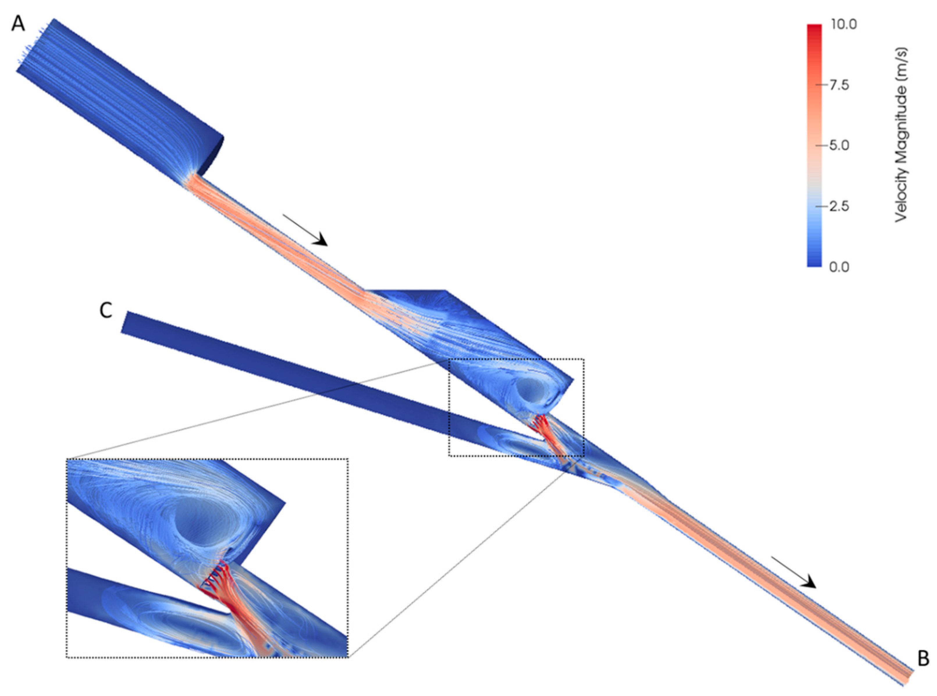
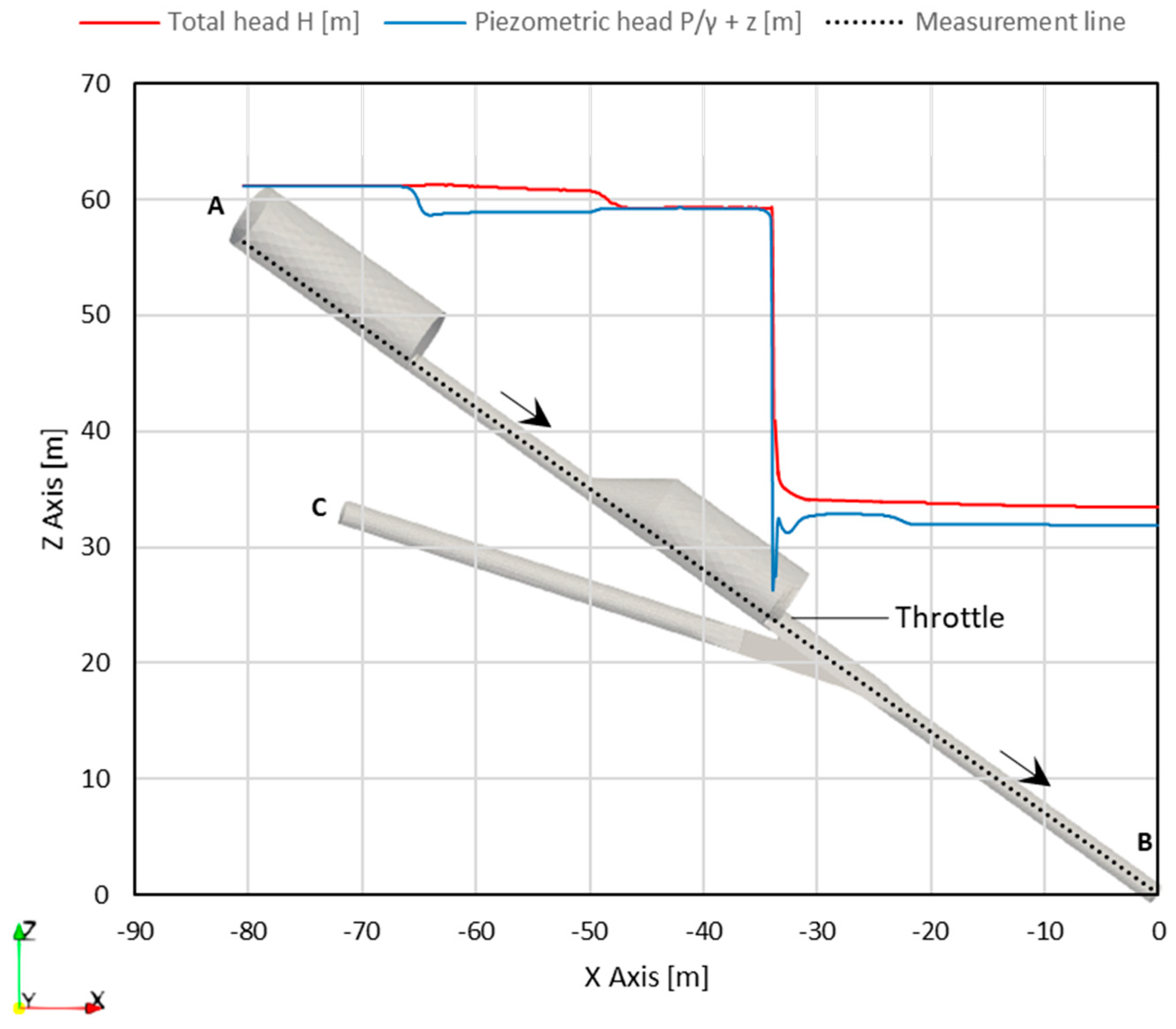
2.2.3. Post-Processing: Visualization of Results and Head Loss Coefficient Estimation
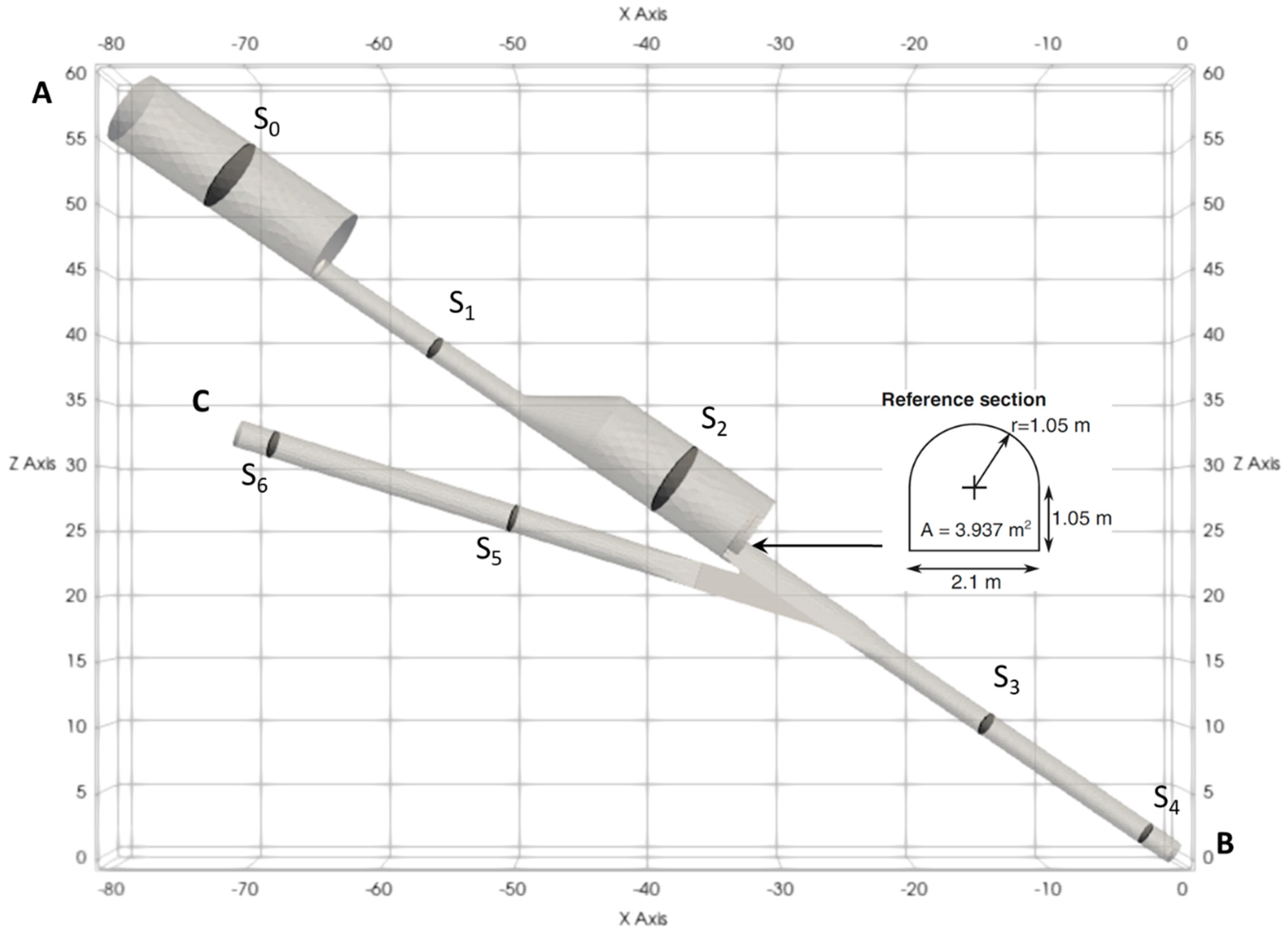
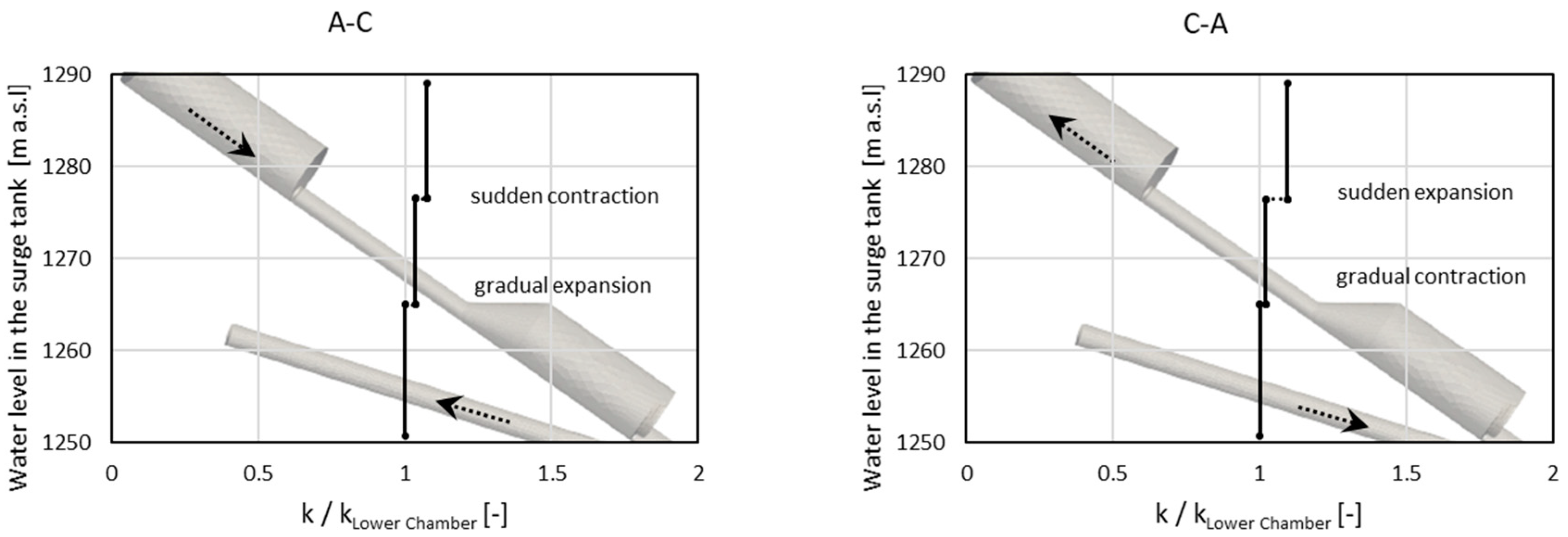
- S1–S5 for direction A–C (flow out of the surge tank during mass oscillation)
- S5–S1 for direction C–A (flow into the surge tank during mass oscillation)
- S1–S4 for direction A–B (flow out of the surge tank following a turbine opening)
- S5–S4 for direction C–B (steady flow during turbine operation)
3. Results
3.1. Validation with the Physical Model Results
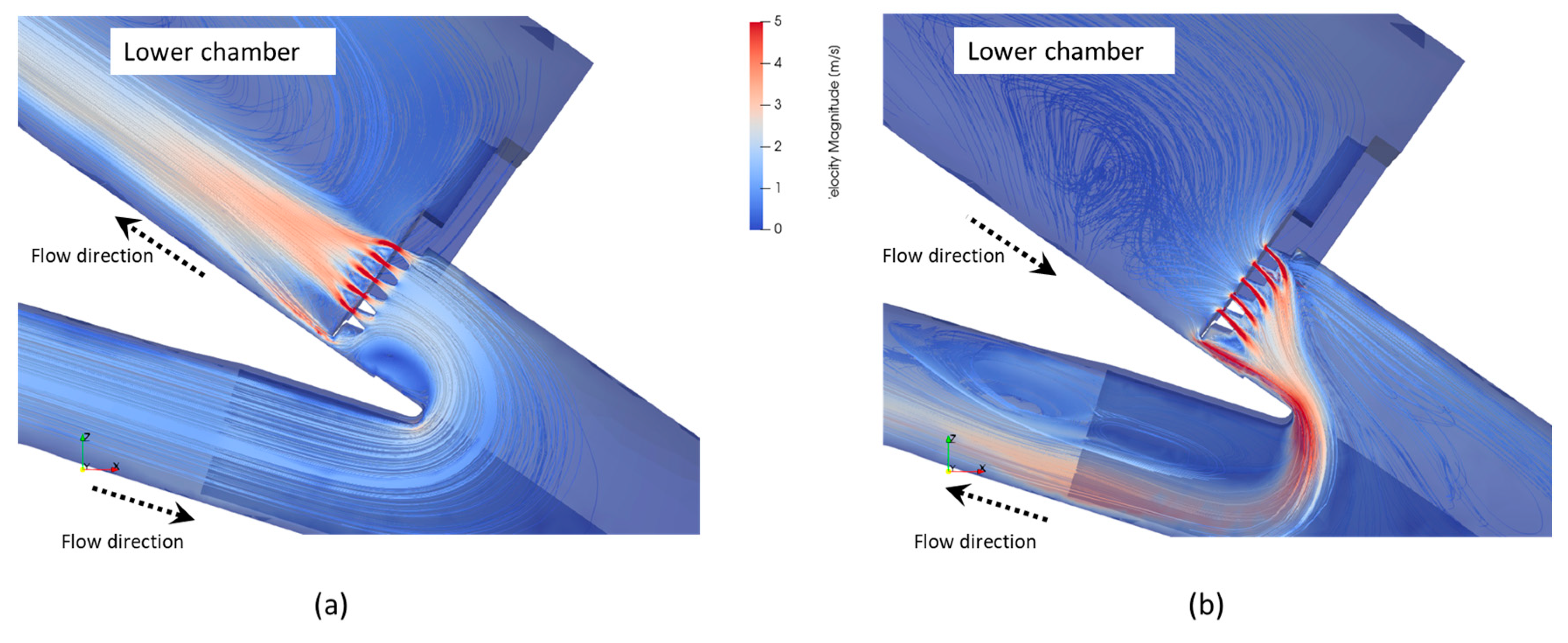
3.2. Impact of the Connecting Gallery
- Section S0 (in the middle of the upper surge tank chamber, above the connecting galley)
- Section S1 (in the middle of the connecting gallery)
- Section S2 (in the middle of the lower surge tank chamber, below the connecting gallery)
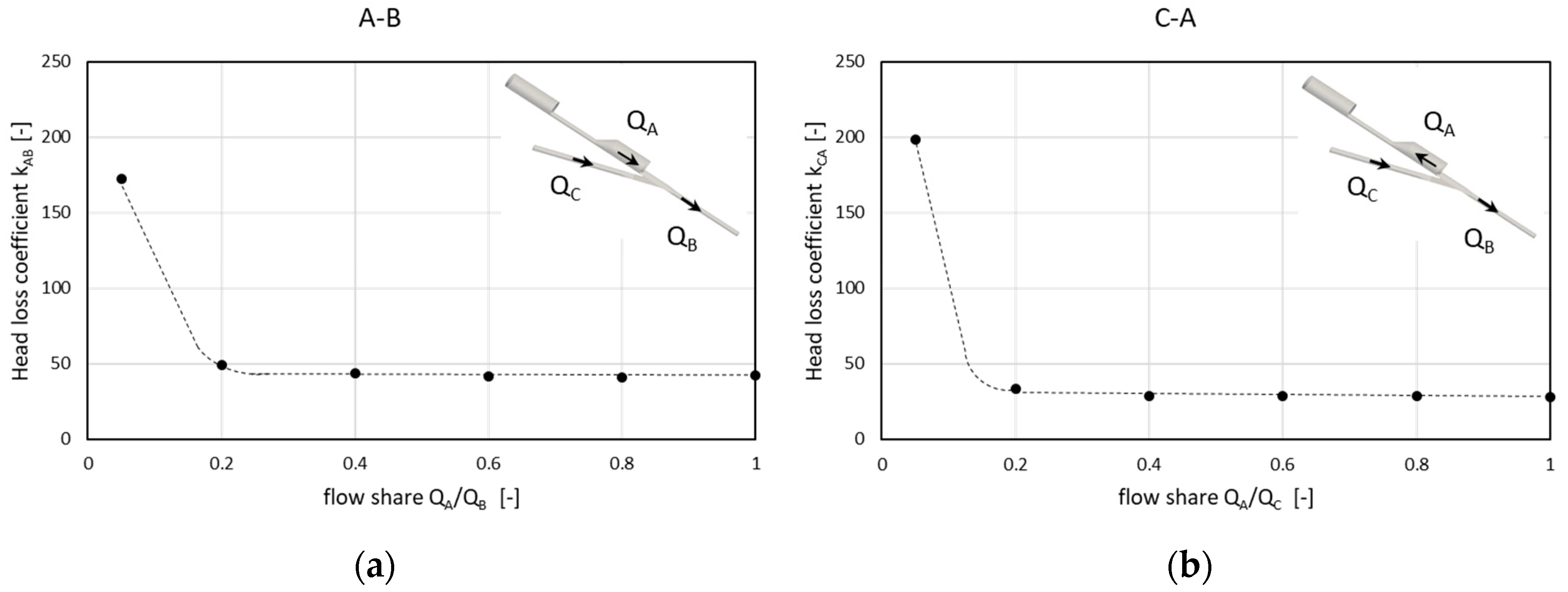
3.3. Impact of the Flow Share
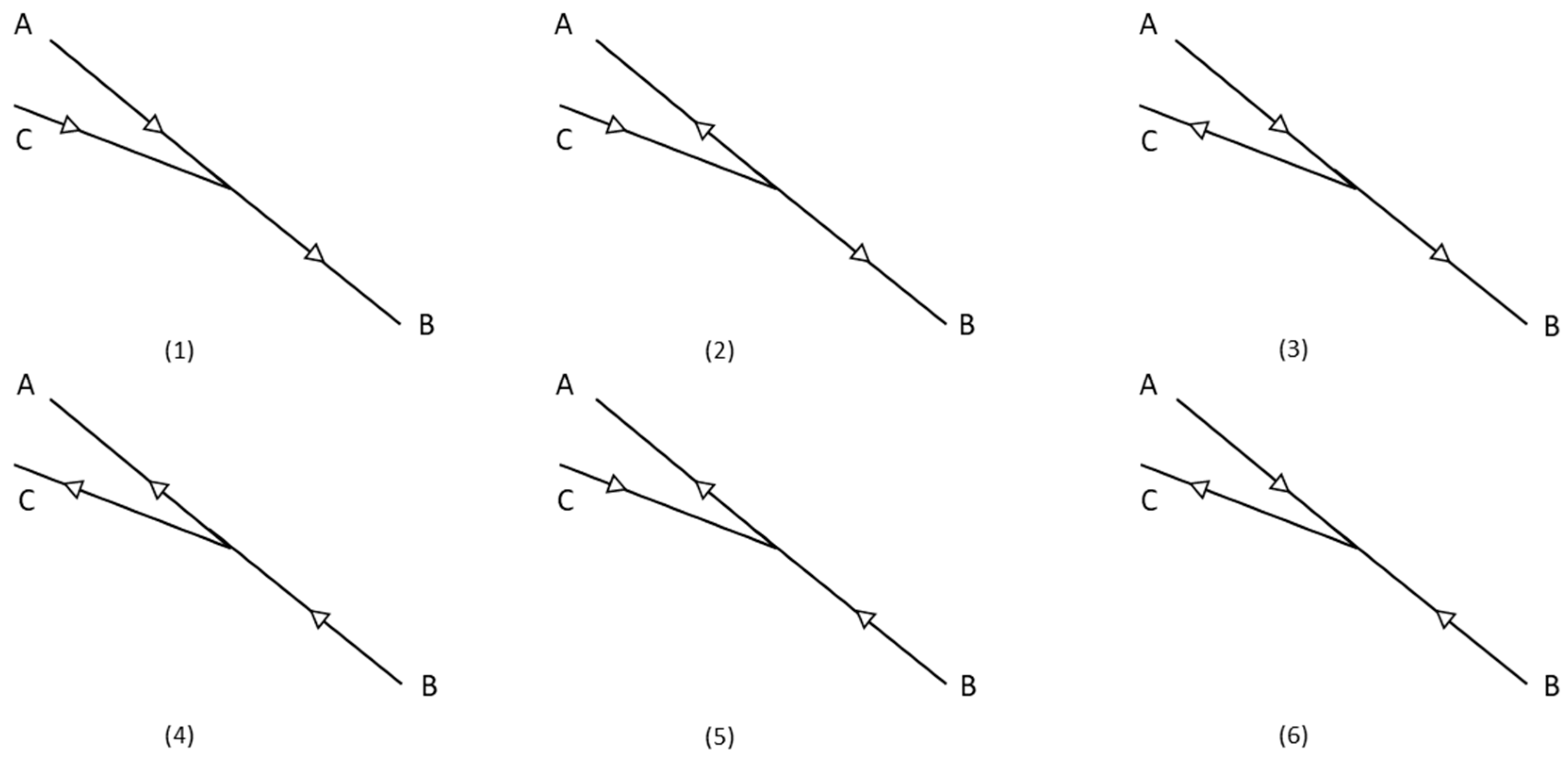
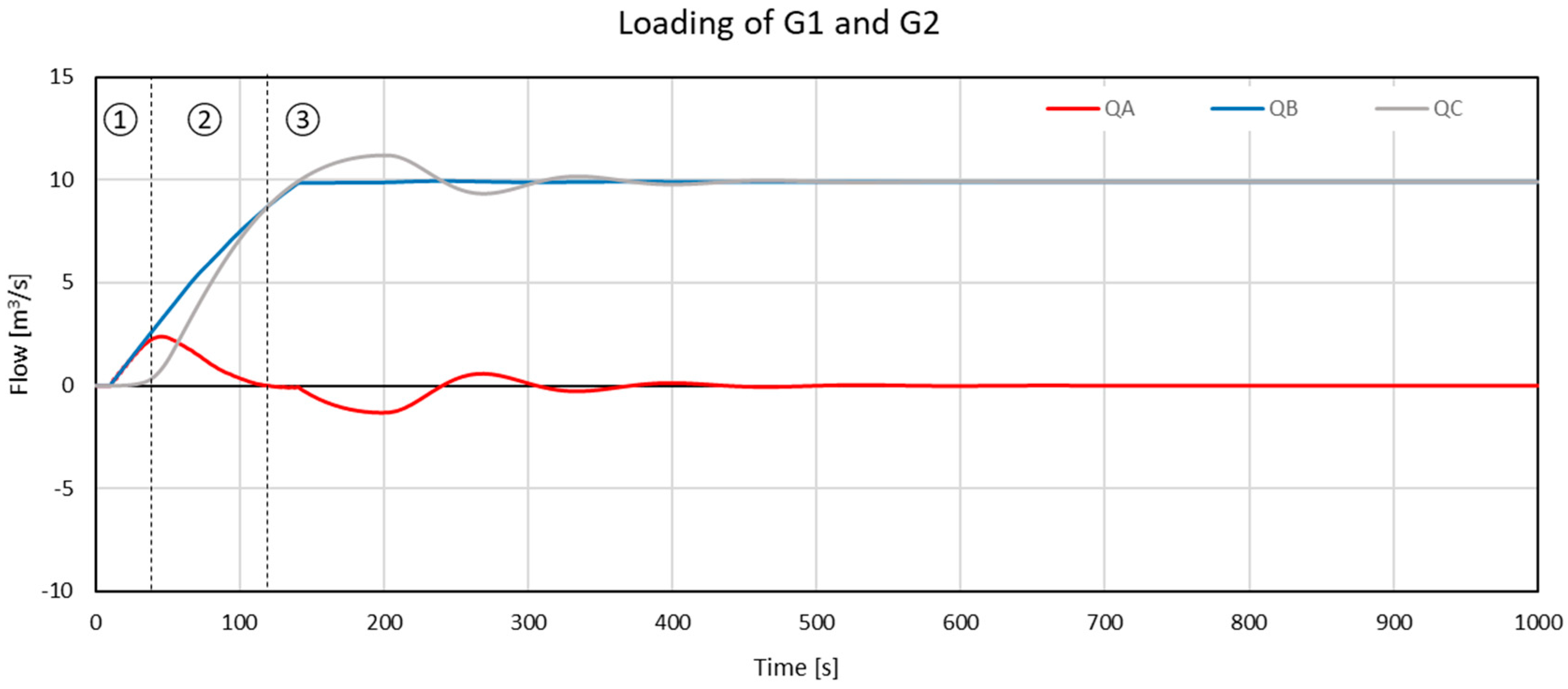
- 0 ≤ t < 40 s: the flow in the pressure tunnel QC is null, which is expected since the surge tank takes the role of the upstream reservoir to supply the penstock with the demanded flow. It is therefore the flow configuration (1) with QA = QB (QC = 0, no flow sharing).
- 40 ≤ t < 120 s: the flow supplied by the tank decreases gradually and the upstream reservoir starts to supply the system with an increasing QC. It is therefore flow configuration (1) with 0 < QA/QB < 1.
- 120 ≤ t < 500 s: mass oscillation between the upstream reservoir and the surge tank takes place. A flow entering the surge tank (negative flow) creates a demand for the flow in the system in addition to the one required by the penstock. This results in an increased pressure tunnel flow QC to accommodate both demands. This phase consists of successive alternations between modes (2) and (1) in which and 0 < QA/QC < 1 and 0 < QA/QB < 1. After 500 s, the steady generation mode is reached, and the mass oscillation phenomenon ends.
- 0 < t < 65 s: the flow in the pressure tunnel QC is shared by both the surge tank and the penstock. It is therefore the flow configuration (2) with 0 < QA/QC < 1. Note that the zone in which the flow ratio is below 20% constitutes about 18 s.
- t > 65 s: the flow in the penstock QB becomes null by around 65 s. Then, mass oscillation takes place. In this case, alternations between flow configurations (3) and (2) occur with QB ≈ 0. No flow sharing takes place, QA ≈ QC.
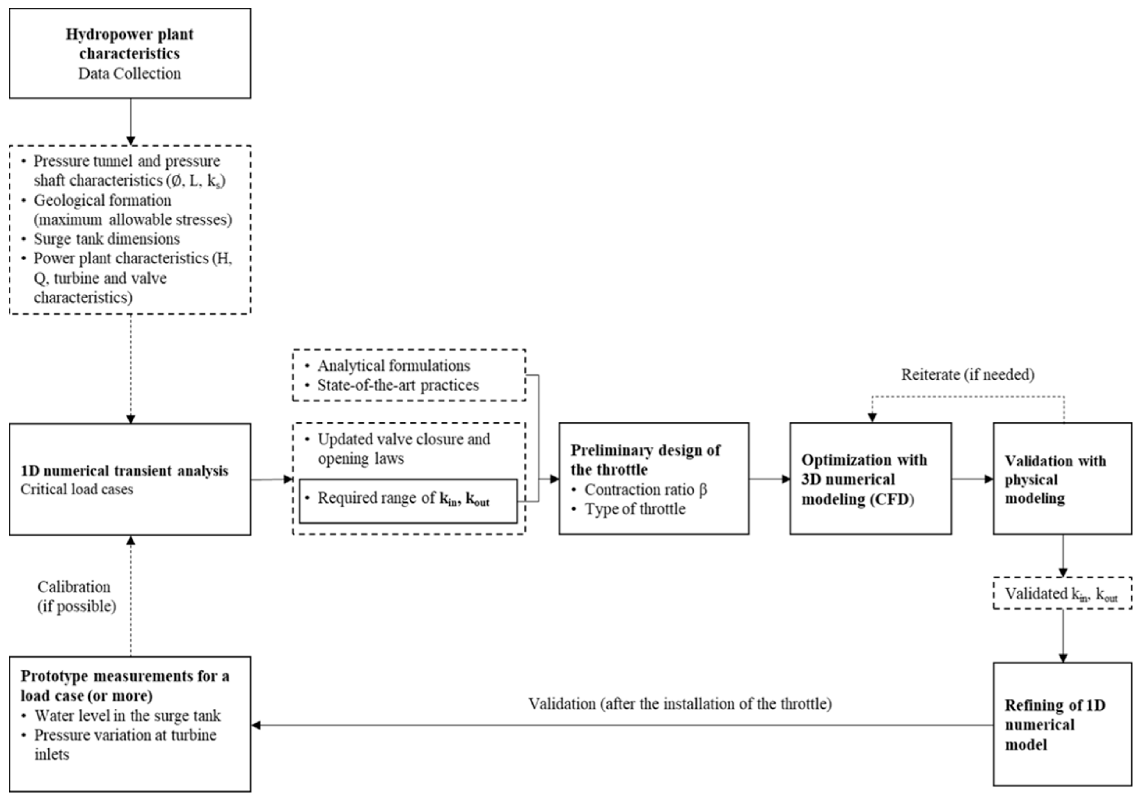
4. Discussion
- 1D numerical modeling:
- Advantages: It is a fast method that can provide sufficient data for analyzing transient events and designing appropriate transient control devices in the system (surge tank dimensions for instance) based on critical load cases.
- Limitations: It can only provide the required head loss coefficients of the throttle and cannot serve as a tool to design its geometry. The throttle is modeled as a local restriction that has specific head loss characteristics without reflecting the real flow conditions (formation of the jet upstream or downstream, development of regions of swirling or flow separation). Current commercial 1D software are unable to model complex geometries of surge shafts, failing to reflect the real flow conditions across the expansion chambers.
- Physical Modeling:
- Advantages: It is adequate to represent the flow conditions of the real system on a reduced scale.
- Limitations: The design, construction, and systematic investigations are time-consuming. A sufficient number of measurements should be done for higher precision. Measurements of very small pressures or velocities that are in the same order of magnitude of the tolerance of the sensors may bias the results. Additionally, physical modeling does not allow obtaining flow parameters or visualizing flow patterns in all locations, despite the common usage of Plexiglas walls and the tests with dye injection. The latter does not lead to perceptible flow field features in a scaled model due to very rapid plume dispersion. Non-intrusive measurements e.g., using ultrasonic Doppler profiler (UVP) or particle image velocimetry (PIV) can reduce this limitation but require advanced instrumentation.
- 3D Numerical Modeling:
- Advantages: It allows the extraction of hydrodynamic values (numerical measurements) anywhere in the flow domain as well as the visualization of the flow fields on a prototype scale, the flow field being the major indicator of the effectiveness of the throttle arrangement and design. Iterations on the numerical model in the geometry optimization process are generally not as costly as the ones constructed and tested on a physical scale model.
- Limitations: It is accompanied by errors and uncertainties in the modelling approaches that should preferably be validated by a physical model. It takes a long computational time if a high mesh precision is required; a symmetry boundary condition may not always be used since a symmetrical geometry does not always imply symmetrical flow conditions.
- Hybrid Modeling As a Necessity
5. Conclusions
Author Contributions
Funding
Acknowledgments
Conflicts of Interest
References
- Office Fédéral de L’énergie OFEN. Potentiel Hydroélectrique de la Suisse: Évaluation du Potentiel de Développement de la Force Hydraulique Dans le Cadre de la Stratégie Énergétique 2050; Département fédéral de l’environnement, des transports, de l’énergie et de la communication DETEC: Berne, Switzerland, 2019. [Google Scholar]
- Adam, N.J.; De Cesare, G.; Nicolet, C.; Billeter, P.; Angermayr, A.; Valluy, B.; Schleiss, A.J. Design of a Throttled Surge Tank for Refurbishment by Increase of Installed Capacity at a High-Head Power Plant. J. Hydraul. Eng. 2018, 144, 05017004. [Google Scholar] [CrossRef]
- Kendir, T.E.; Ozdamar, A. Numerical and experimental investigation of optimum surge tank forms in hydroelectric power plants. Renew. Energy 2013, 60, 323–331. [Google Scholar] [CrossRef]
- Li, Y.T. Orifice head loss in the T-section of a throttled surge tank. Water Power 1972, 24, 326–334. [Google Scholar]
- Adam, N.J.; De Cesare, G.; Schleiss, A. Surge Tank Throttles for Safe and Flexible Operation of Storage Plants; Hydro Conference: Montreux, Switzerland, 2016; Volume 8. [Google Scholar]
- Alligne, S.; Rodic, P.; Arpe, J.; Mlacnik, J.; Nicolet, C. Determination of Surge Tank Diaphragm Head Losses by CFD Simulations. In Advances in Hydroinformatics; Gourbesville, P., Cunge, J., Caignaert, G., Eds.; Springer: Singapore, 2014; pp. 325–336. ISBN 978-981-4451-41-3. [Google Scholar]
- Gabl, R.; Righetti, M. Design criteria for a type of asymmetric orifice in a surge tank using CFD. Eng. Appl. Comput. Fluid Mech. 2018, 12, 397–410. [Google Scholar] [CrossRef]
- De Cesare, G.; Adam, N.J.; Nicolet, C.; Angermayr, A.; Valluy, B. Surge Tank Geometry Modification for Power Increase; Hydro Conference 2015: Bordeaux, France, 2015; p. 16. [Google Scholar]
- Hachem, F.; Nicolet, C.; Duarte, R.; De Cesare, G.; Micoulet, G. Hydraulic Design of the Diaphragm’s Orifice at the Entrance of the Surge Shaft of FMHL Pumped-storage Power Plant. In Proceedings of the 35th IAHR World Congress, Chengdu, China, 8–13 September 2013. [Google Scholar]
- Adam, N.J.; De Cesare, G.; Schleiss, A.J. Influence of geometrical parameters of chamfered or rounded orifices on head losses. J. Hydraul. Res. 2019, 57, 263–271. [Google Scholar] [CrossRef]
- Idelchik, I.E. Handbook of hydraulic resistance, 2nd ed.; Revised and Augmented; Hemisphere Publishing Corporation: New York, NY, USA, 1986. [Google Scholar]
- Richter, W.; Dobler, W.; Knoblauch, H. Hydraulic and numerical modelling of an asymmetric orifice within a surge tank. In Proceedings of the 4th IAHR International Symposium on Hydraulic Structures, Porto, Portugal, 9–11 February 2012; p. 7. [Google Scholar]
- An, J.F.; Zhang, J.; Cheng, S. Coefficients of Local Head Losses in Steady-State Flow of Throttled Surge Tanks with Standpipe by CFD. Adv. Mater. Res. 2013, 677, 290–295. [Google Scholar] [CrossRef]
- Gardel, A.; Rechsteiner, G.F. Les Pertes de Charge Dans les Branchements en té des Conduites de Section Circulaire. In Bulletin Technique de la Suisse Romande; Publication/Ecole Polytechnique Fédérale Lausanne: Lausanne, Switzerland, 1970; Volume 118. [Google Scholar]
- Zhou, J.; Palikhe, S.; Cai, F.; Liu, Y. Experimental and simulation-based investigations on throttle’s head loss coefficients of a surge tank. Energy Sci. Eng. 2020, 1–12. [Google Scholar] [CrossRef]
- Klasinc, R.; Bilus, I. Experimental and numerical approach to surge tank improvements. In Proceedings of the International Symposium on Water Management and Hydraulic Engineering, University of Ss Cyril and Methodius, Skopje, Macedonia, 1–5 September 2009; pp. 339–348. [Google Scholar]
- Kim, S.-H. Design of surge tank for water supply systems using the impulse response method with the GA algorithm. J. Mech. Sci. Technol. 2010, 24, 629–636. [Google Scholar] [CrossRef]
- Gabl, R.; Achleitner, S.; Neuner, J.; Götsch, H.; Aufleger, M. 3D-numerical optimisation of an asymmetric orifice in the surge tank of a high-head power plant. In Proceedings of the 34th IAHR Congress 2011-Balance and Uncertainty: Water in a Changing World, Incorporating the 33rd Hydrology and Water Resources Symposium and the 10th Conference on Hydraulics in Water Engineering; International Association for Hydro-Environment Engineering and Research (IAHR), Brisbane, Australia, 26 June–1 July 2011; pp. 2428–2435. [Google Scholar]
- Nabi, G.; Kashif, M.; Tariq, M. Hydraulic Transient Analysis of Surge Tanks: Case Study of Satpara and Golen Gol Hydropower Projects in Pakistan. Pak. J. Eng. Appl. Sci. 2011, 8, 15. [Google Scholar]
- Schneider, J.; Richter, W.; Knoblauch, H.; Zenz, G. Physikalische und numerische Untersuchungen von Wasserschlössern im Rahmen der Neuerrichtung von Pumpspeicherkraftwerken. Simul. Model. Wasserbau Wasserwirtsch. 2014, 50, 313–322. [Google Scholar]
- Meusburger, P. Study of different surge tank design for Observer-muntwerk II. Wasserwirtschaft 2015, 105, 53–57. [Google Scholar] [CrossRef]
- Bhattarai, K.P.; Zhou, J.; Palikhe, S.; Pandey, K.P.; Suwal, N. Numerical Modeling and Hydraulic Optimization of a Surge Tank Using Particle Swarm Optimization. Water 2019, 11, 715. [Google Scholar] [CrossRef]
- Versteeg, H.K.; Malalasekera, W. An Introduction to Computational Fluid Dynamics: The Finite Volume Method, 2nd ed.; Pearson Education Ltd.: Harlow, UK; New York, NY, USA, 2007; ISBN 978-0-13-127498-3. [Google Scholar]
- Christensen, R.T.; Spall, R.E.; Barfuss, S.L. Application of Three RANS Turbulence Models to Aged Water Transmission Pipes. J. Hydraul. Eng. 2011, 137, 135–139. [Google Scholar] [CrossRef]


| Investigated Flow Direction | k (Combined Data Series Best Fit) | k (Experimental Data Series) | k (Numerical Data Series) | Relative Difference (%) |
|---|---|---|---|---|
| A–C (S1–S5) | 45.7 ± 0.48 | 45.9 ± 0.70 | 45.2 ± 0.12 | 1.42 |
| A–B (S1–S4) | 40.6 ± 0.35 | 39.8 ± 0.35 | 42.1 ± 0.33 | 6.05 |
| C–A (S5–S1) | 28.4 ± 0.25 | 29.6 ± 0.54 | 28.2 ± 0.013 | 4.93 |
| C–B (S5–S4) | 0.95 ± 0.02 | 0.98 ± 0.02 | 0.86 ± 0.004 | 12.24 |
Publisher’s Note: MDPI stays neutral with regard to jurisdictional claims in published maps and institutional affiliations. |
© 2020 by the authors. Licensee MDPI, Basel, Switzerland. This article is an open access article distributed under the terms and conditions of the Creative Commons Attribution (CC BY) license (http://creativecommons.org/licenses/by/4.0/).
Share and Cite
Seyfeddine, M.; Vorlet, S.; Adam, N.; De Cesare, G. Holistic Design Approach of a Throttled Surge Tank: The Case of Refurbishment of Gondo High-Head Power Plant in Switzerland. Water 2020, 12, 3440. https://doi.org/10.3390/w12123440
Seyfeddine M, Vorlet S, Adam N, De Cesare G. Holistic Design Approach of a Throttled Surge Tank: The Case of Refurbishment of Gondo High-Head Power Plant in Switzerland. Water. 2020; 12(12):3440. https://doi.org/10.3390/w12123440
Chicago/Turabian StyleSeyfeddine, Mona, Samuel Vorlet, Nicolas Adam, and Giovanni De Cesare. 2020. "Holistic Design Approach of a Throttled Surge Tank: The Case of Refurbishment of Gondo High-Head Power Plant in Switzerland" Water 12, no. 12: 3440. https://doi.org/10.3390/w12123440
APA StyleSeyfeddine, M., Vorlet, S., Adam, N., & De Cesare, G. (2020). Holistic Design Approach of a Throttled Surge Tank: The Case of Refurbishment of Gondo High-Head Power Plant in Switzerland. Water, 12(12), 3440. https://doi.org/10.3390/w12123440