1. Introduction
A disastrous, sudden inrush of groundwater often floods tunnels and even whole coal mines in their production and construction. Plugging and grouting can quickly and effectively control water hazards, separating the water-flooded area and production area. If the location of the inrush pathway is known, the plugging and grouting can be carried out in that pathway. However, the water-conducting pathway is difficult to discover in most situations. In these cases, emergency relief is usually implemented in a centralized roadway flooded with water. A centralized roadway here generally refers to a tunnel that concentrates the water inrush flow, where there are no other tunnels within 30 m. The grouting and blocking of water are generally carried out in the underground channel under the hazardous condition of water flowing at high pressure and speed.
A grouting and sealing project in an inundated mine tunnel is usually implemented in two stages: pouring aggregate and grouting reinforcement. The purpose of pouring aggregate is to form a water-blocking section in the tunnel through the accumulation of aggregates and to change the pipeline flow to a permeate flow. The purpose of the grouting reinforcement is to block the voids in the accumulating mass to seal off the water, with cement slurry. Therefore, aggregate pouring is a necessary prerequisite for effective grouting, while effective grouting plays a key role in successful water blocking. Moreover, the selection of aggregate is a key issue in grouting-shutoff engineering. In a pouring project, both fine aggregates, such as fly ash and sand, and coarse aggregates, such as gravel and pebbles of various particle sizes, are generally used. In practice, the maximum particle size of the aggregate should generally not exceed 1/3 to 1/4 of the borehole’s inner diameter [
1,
2]. The aggregate is usually inserted with a special orifice injection device and then carried by a moderate and stable water flow through the borehole. A water–solid mass ratio between 5:1 and 15:1 is often selected [
1,
2]. According to the groundwater-inrush flow rate and the roadway environment, different pouring sequences are often adopted, such as pouring coarse particles first and then pouring fine ones or vice versa, and pouring coarse particles upstream and fine particles downstream or vice versa. The ultimate aim is to achieve the best efficiency of plugging.
Case histories and experiences of controlling groundwater inrush using this approach in mine tunnels have been discussed by many researchers and engineers in the literature. The process of aggregate accumulation and plugging is divided into three stages: the bottom-laying stage, filling stage and plugging stage [
3]. After the aggregate pouring is completed, the pipeline flow in the tunnel becomes a permeate flow [
1,
2,
4]. Some new technologies and materials have been applied in the construction of the water-retention section in the inundated tunnel. The feasibility of using fine aggregate in the water-blocking treatment of a tunnel with flow water has been discussed [
5]. Grouting from the directional drilling of boreholes on the ground for the rapid construction of a water-retention structure in the tunnel was used in a groundwater-inrush control project in different coal mines, such as in the Luotuoshan coal mine, Inner Mongolia; the Yuchang coal mine, Shaanxi; and the Panji coal mine No.2, Anhui [
6,
7,
8,
9]. The method of placing grouting bags at fixed points and inject quick-setting and high-strength grouts was used to achieve the rapid and controllable blocking of tunnels with high flow rates [
10].
Research on the transportation and plugging mechanism of the solid–liquid mixture during the pouring of aggregates in a flooded tunnel requires knowledge of the hydraulics, sediment kinematics, solid–liquid two-phase flow and suspension rheology. The results will provide a theoretical basis for the control of tunnel-water inrush disasters and improving engineering design. Experimental investigations and numerical simulations have been widely used for understanding the process of pouring aggregate in a tunnel. Aggregate-pouring techniques, the mechanism of the grouting reinforcement of the accumulating aggregate mass and the criteria for judging the water-retention capacity of the water-blocking section have been investigated experimentally and theoretically [
8]. Experiments of pouring aggregate into a horizontal pipeline through a single borehole showed that the factors influencing the efficiency of plugging, in descending order, were the aggregate particle size, followed by the initial velocity of the water flow and then the water–solid mass ratio [
11]. An experimental setup for placing grouting bags has recently been developed [
12]. The study of material transportation in horizontal pipes has shown some similarity with the movement and sedimentation of aggregates in tunnels. The Eulerian–Lagrangian method and turbulent liquid–solid slurries in horizontal pipes were used to investigate single-dispersed fine-particle flow at high concentrations [
13,
14,
15,
16]. A new two-fluid model (TFM) was proposed and later improved by Messa et al. [
17] and Messa and Matoušek [
18]. Their results confirmed that the TFM is an effective tool for engineering design by comparing with experimental results [
18].
In order to better understand the migration of slurry in multi-void pores, many experimental studies have been carried out. For example, Mohtar et al. [
19] and Jaffal et al. [
20] pointed out that the non-uniformity of soil would create a preferred flow path for the spread of grout, leading to non-uniform grout coverage and thus affecting the effects of penetration grouting. Civan [
21] studied various forces, velocities and other related factors that affect the appearance of pore media through experiments with two modes of flow of particles in and out of pores. Mohtar et al. [
22] studied the post-grouting stability of bentonite in porous media and established the relationship between the yield stress of the bentonite suspension and the critical water conductivity. Bedrikovetskya et al. [
23] and Lenchenkov et al. [
24] studied the flow of colloids in water and porous media, and confirmed the validity of their proposed model, which can also be used to predict potential well plugging. Civan and Vafai [
25] examined the characteristic features of the fundamental flow mechanisms and discussed the essential parameters of relevant modeling approaches for the transportation of gas through dense, porous media. These studies are helpful for understanding the deposition and transportation of aggregates in a tunnel with flowing water and why the order of adding grains sizes is important in plugging the channel.
The hydraulic-pipeline transport of slurries has certain similarities with the accumulation of aggregate in a tunnel with flowing water. The states of solid–liquid mixtures have been classified into three categories—homogeneous, intermediate and heterogeneous—based on the suspension flow of sand and gravel in the water [
26]. Wasp et al. categorized the flow regimes of solid materials in pipelines into two types: homogeneous and heterogeneous [
27]. Solid particles are divided into bed load or suspended load by Fei [
28]. The transport of sand–water slurries along a horizontal pipeline has been investigated by many researchers, such as Soepyan et al. [
29] and Zouaoui et al. [
30]. The transition of slurry flow from heterogeneous to homogeneous was investigated by Miedema [
31]. This literature on slurry flow in pipelines is helpful for understanding the movement and deposition of aggregates in a tunnel with flowing water.
The water-pressure changes along a pipeline can help in understanding the mechanism in the two-phase flow to illustrate friction loss, and the reduction of pressure in a turbulent flow state has been evaluated [
32,
33]. Formulas to calculate the hydraulic gradient or head loss have been developed based on energy considerations [
34,
35]. Dimensional analysis methods have been used to predict drops in pressure in the flow of solid–liquid suspensions [
36,
37]. The hydraulic gradient has been shown to be influenced by the particle size, specific gravity and fluid viscosity [
38,
39].
The abovementioned engineering practices represent very important experience for similar projects. Some results from the theoretical, experimental and numerical studies are fundamental for understanding the mechanism of the accumulation of plugging by pouring aggregates to control water inrush or salvage underground mines or projects. However, in-depth research is lacking in quantity and universality due to the concealment of underground engineering. Among many controversies, there are some issues commonly raised because they are important for the effective control of groundwater-inrush accidents. One controversy is the selection of the particle size of the aggregates and their pouring order, i.e., whether it is better to pour coarse aggregates first and then introduces the fine ones or vice versa. Another controversy is the order of pouring by boreholes, i.e., whether to pour in the downstream borehole first and then in the upstream borehole or vice versa. Therefore, the first objective of this study was to investigate the effects of the pouring order for the aggregates of different particle sizes on the plugging effects using a visualized experimental setup. The second objective was to investigate the sequence of pouring from different boreholes upstream or downstream of the water inrush point. The results from field investigations were compared with those from experiments. Finally, a suitable pouring order regarding the particle sizes of the aggregates and the borehole locations is discussed and recommended for achieving better plugging.
2. Materials and Methods
2.1. Materials
Three groups of aggregate particle sizes in the experiments were selected: 0.25–0.5, 0.5–2 and 2–5 mm. The sand and gravel were screened and washed to remove finer soil and impurities to ensure the clear visualization of the aggregate movement process. Water was added to the funnel to saturate the aggregate to form a water–sand mixture flow. The water–solid mass ratio was maintained between 1:1 and 2:1, and the pouring speed was controlled using a valve, while avoiding hole blocking.
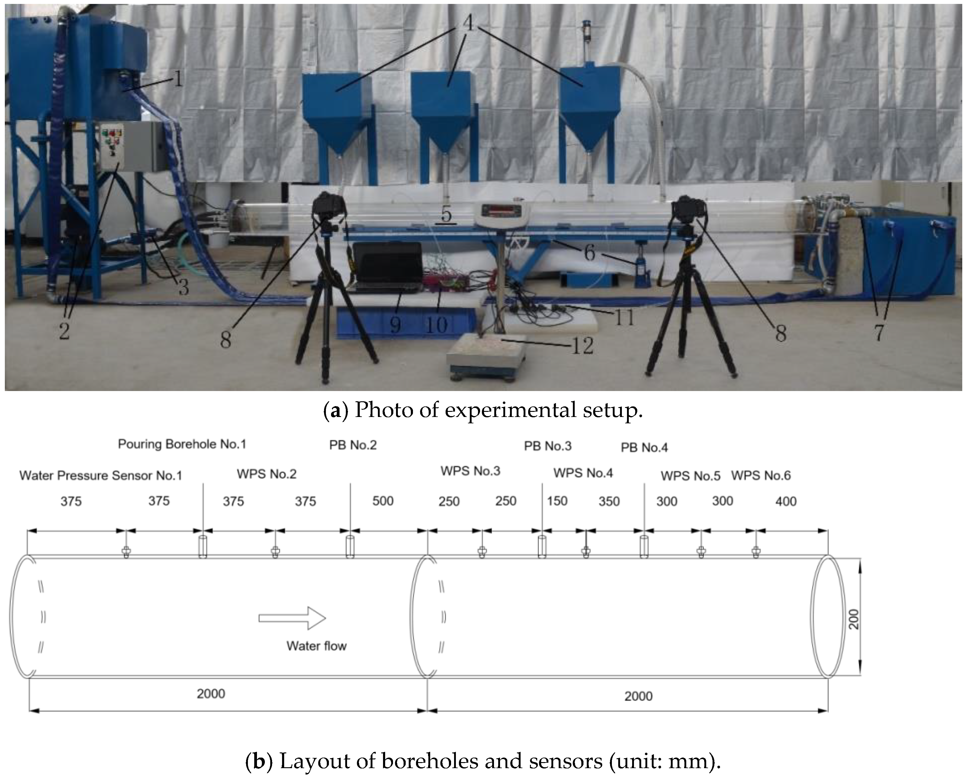
The tunnel replica is made up of an acrylic circular tube unit and an adjustable angle support platform device. The acrylic tube consists of two round tubes with an internal diameter of 200 mm, wall thickness of 10 mm and length of 2000 mm, in which the middle is connected by a flange and sealing ring. The tunnel model has four boreholes of 25 mm for pouring and six measurement holes with a diameter of 6 mm to connect water-pressure sensors. At both ends of the tube, there are high-strength plates with inlet holes and drainage holes. There is a round plate evenly covered with small holes near the inlet and outlet, which can change the water flow state to a uniform pipe flow. A geometric ratio of 20 between the prototype and the model was selected based on the Euler criterion and the gravity similarity criterion. Based on previous research and similarity criteria, the pipeline can be used to simulate a tunnel with a cross-sectional area of 12 m
2, length of 80 m and water-inrush flow of 6440 m
3/h [
11].
2.2. Experimental Setup
The efficiency of the plugging achieved by injecting aggregates into a submerged tunnel with flowing water is affected by many factors, including natural and engineering factors, such as the tunnel inclination, water flow rate, distance between the boreholes, aggregate particle size, water–solid mass ratio and injection speed. An experimental setup that could provide a constant water head, and adjustable and recyclable water flow at different flow rates was developed.
Figure 1 shows a schematic and photo of the setup. It could control the water–solid mass ratio and pouring speed, as well as collect the data of the flow rate and water pressure in real time. The aggregate accumulation and migration images in the pipeline were captured for process analysis.
2.3. Scheme of the Experiments
In order to investigate the influence of the pouring order on the plugging effect of pouring aggregate from multiple boreholes, two groups of tests were devised by considering the order of pouring the aggregates with different particle sizes and locations.
In engineering practice, the orders of pouring finer particles first and coarser particles later and pouring fine particles upstream and coarse ones downstream have been adopted by the majority, but there are still some disagreements [
3,
4,
8,
9]. The contrary opinion recommends the order of pouring coarser particles first and finer particles later because the finer particles may fill the voids in between coarser ones and enhance the plugging effect. Therefore, the purpose of Trial No. 1 was to investigate the influence of the pouring orders regarding different times and different particle sizes. The same pouring order was chosen in the field case of this study. The reason for the selection of pouring order in Trial No. 2 is to investigate the influence of different pouring orders in upstream and downstream boreholes. The results from Trial Nos. 1 and 2 could then be compared, which was lacking in the previous investigations. Previous studies focused on the influencing factors for pouring aggregate into a horizontal pipeline through a single borehole but lacked the investigation of pouring via multiple boreholes and in different orders.
In the tests, three boreholes were used for pouring and one was used as a vent. Images and data were obtained from cameras, water meters and DataTaker collectors, which were then used to analyze and discuss the influence of different pouring sequences on the efficiency of the plugging. The two groups of trials were as follows:
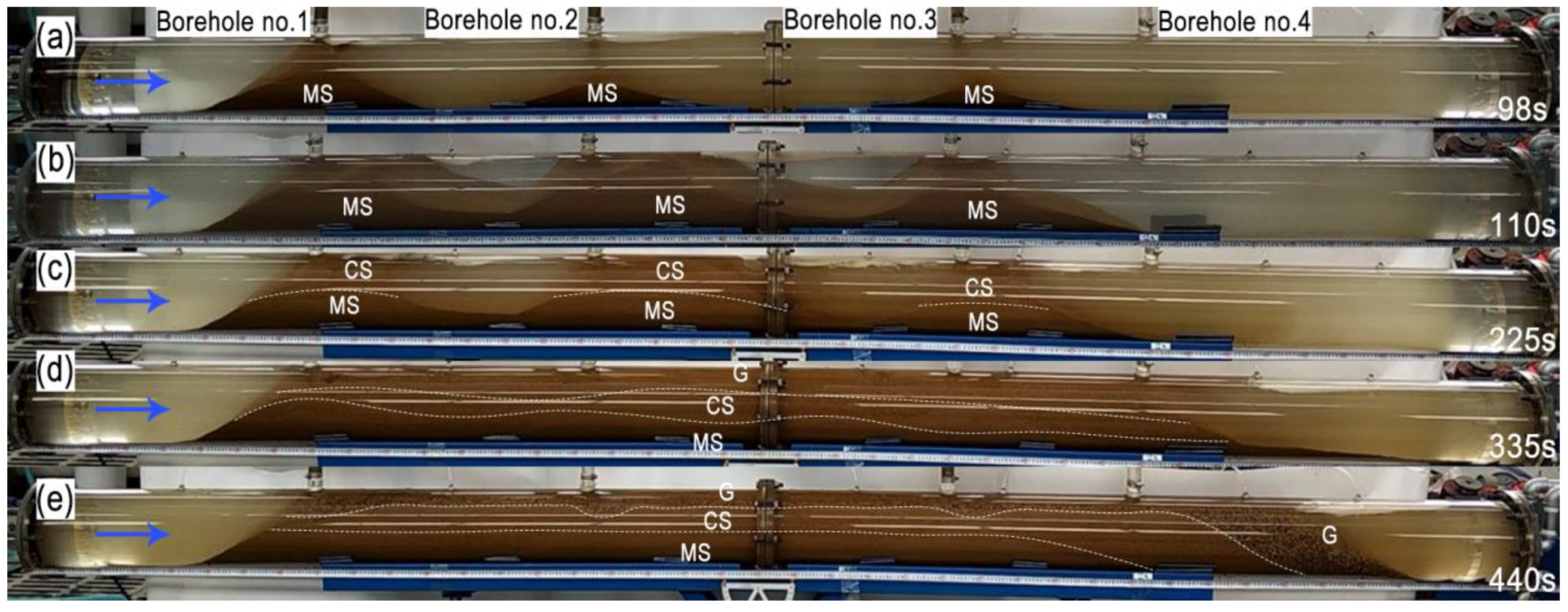
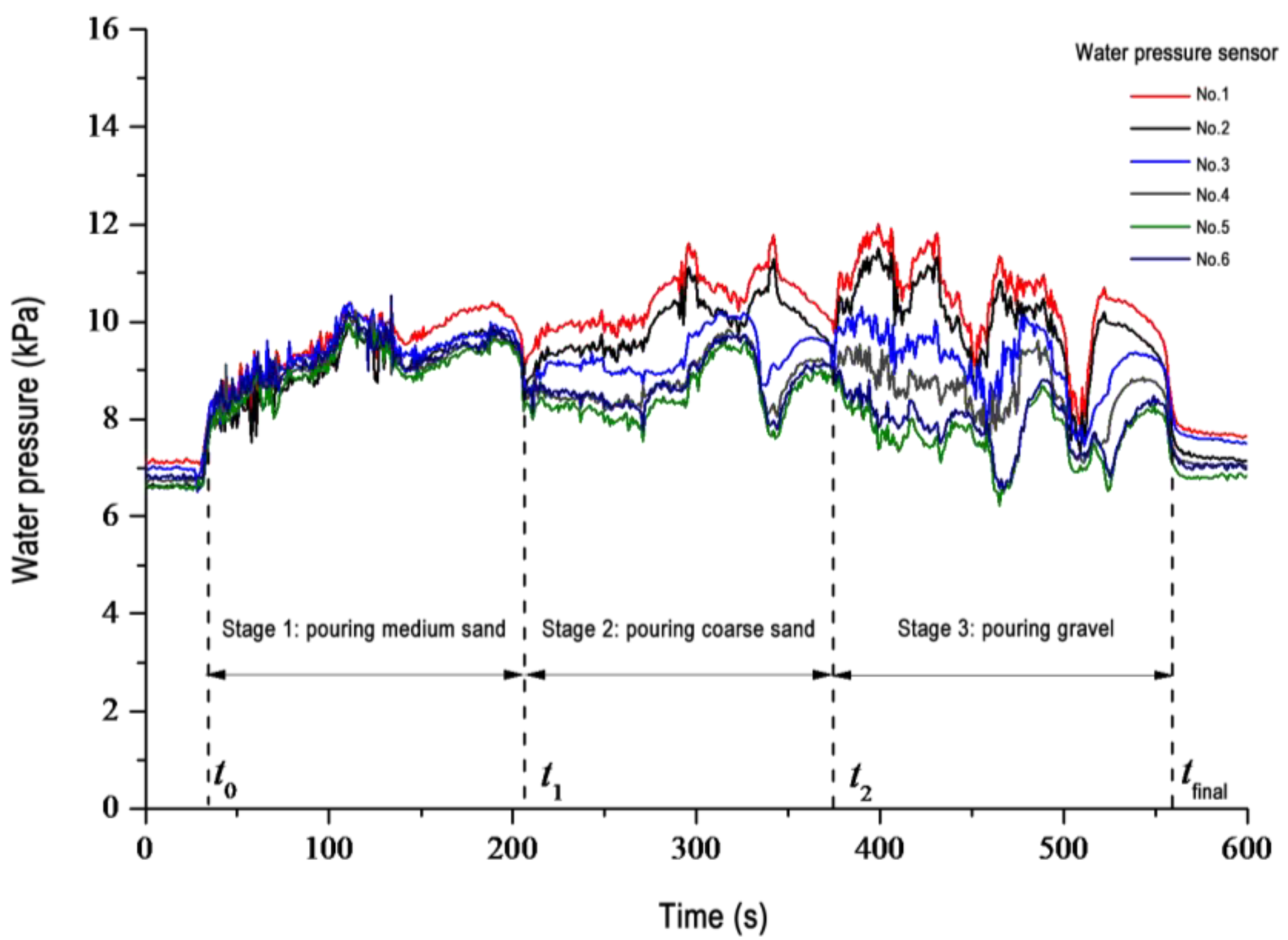
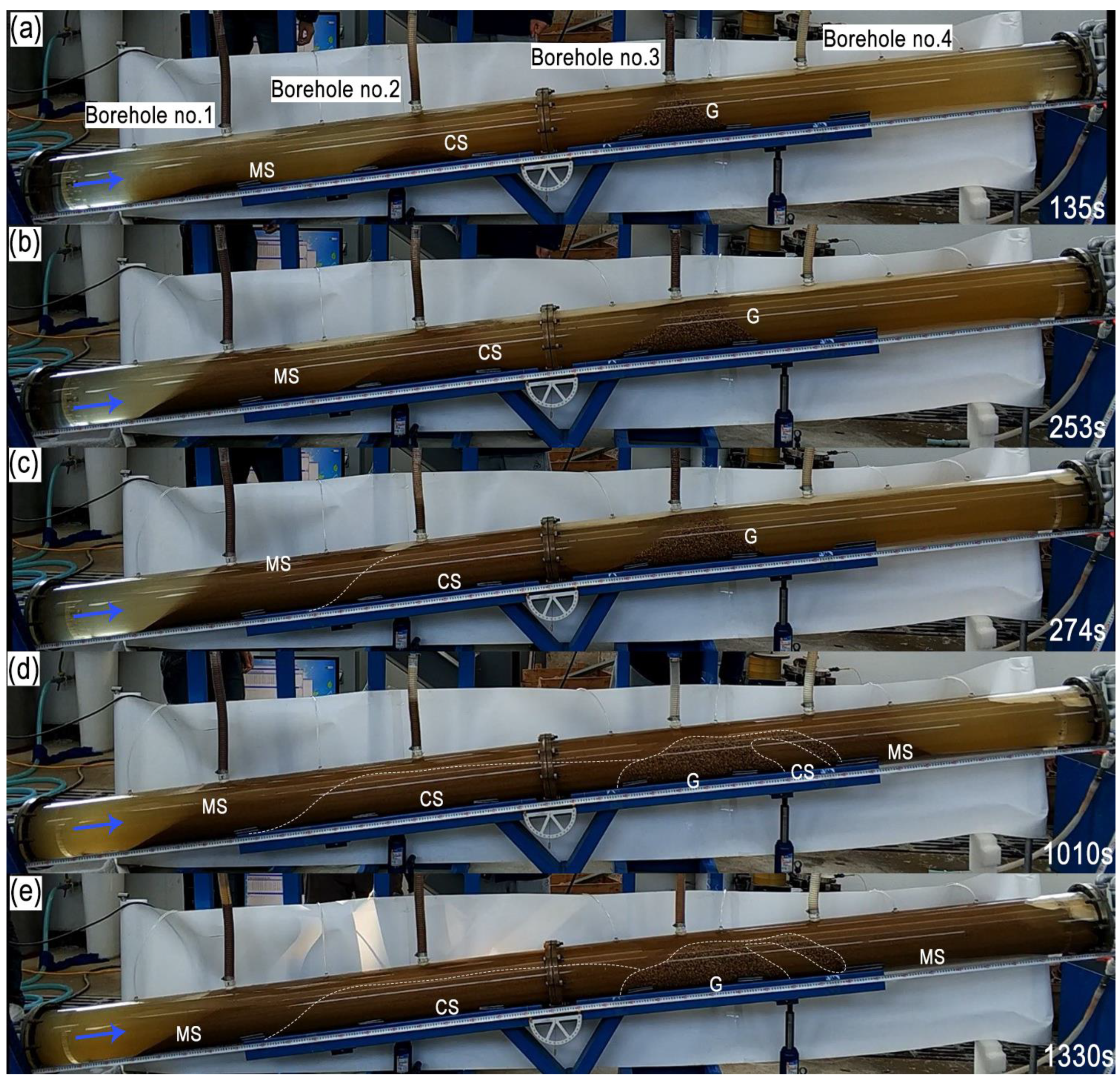
(1) Trial No. 1 was a trial of pouring fine aggregates first and pouring the coarse ones later, focusing on the pouring order for the different particle sizes at different times. Specifically, Borehole Nos. 1, 2 and 3 were used as pouring boreholes and Borehole No. 4 was used as a vent. The same particle size of aggregate was poured through the three pouring boreholes at the same time. The pouring order was pouring medium sand (0.25–0.5 mm) first, coarse sand (0.5–2 mm) second, and gravel sand (2–5 mm) last, according to the particle sizes used in the field case and similarity criterion. The flow-rate scale was 4.47, calculated from a geometric ratio of 20. The flow speed in the water-inrush tunnel in the Panji coal mine No. 2 is 7 cm/s. A water flow speed of 1.5 cm/s was chosen. In the rescue of flooded mines, blocking is generally implemented in a horizontal tunnel or an uphill tunnel with a small inclination. Therefore, an inclination angle of 0° for the tunnel in Trial No. 1 was chosen, while 8° was chosen in Trial No. 2. The process involved pouring medium sand at a rate of 700 g/s for 130 s, coarse sand at 270 g/s for 165 s and gravel at 160 g/s for 190 s.
(2) Trial No. 2 was a trial of pouring fine particles into the borehole at the upstream location first and then pouring coarse particles in the borehole downstream, focusing on the pouring order for the different particles at different locations relative to the water-inrush point. Borehole Nos. 1, 2 and 3 were the same as those in Trial No. 1, being used as pouring boreholes, and Borehole No. 4 was used as a vent. Different particle sizes of the aggregate were poured into the pouring boreholes at the same time. Medium sand (0.25–0.5 mm) was poured into Borehole No. 1; coarse sand (0.5–2 mm), into Borehole No. 2; and gravel (2–5 mm), into Borehole No. 3. A water flow speed of 1.5 cm/s was selected, and the inclination angle of the tunnel was 8°. After completing this phase of the experiment, the pipe was filled until the portion behind Borehole No. 1 was fully filled. This phase is called the pipeline-filling phase. The pouring rate was 90 g/s in Borehole No. 1, 40 g/s in Borehole No. 2 and 30 g/s in Borehole No. 3, respectively; pouring lasted for 900 s in all cases.
2.4. Site Investigation
On 23 May 2017, at 22:51, an accident of groundwater inrush occurred from a tunnel in the floor of panel 12,123 of the Panji coal mines No.2, Huainan city, Anhui province, China. The flow rate suddenly increased to 3024 m3/h at 22:46 on the 25th, and it continued to increase and was greater than the drainage capacity of the coal mine, causing the mine to be flooded. It was estimated that the water flow rate was 14,000 m3/h immediately after the flooding.
During the water inrush, the water levels in the observation boreholes of the Ordovician limestone aquifer changed greatly. For instance, by 27 May, the water level in a borehole 1170 m away from the inrush area decreased by 145.11 m; in another borehole 1400 m away, it decreased by 133.52 m. Since there was no large fault structure explored in the water-inrush area, the pathway of the water should have been a smaller hidden Karst column.
The option of pouring aggregate and grouting reinforcement treatment was chosen from the different options for salvaging the mine. During the treatment period, the water source was explored and sealed. The water-blocking project was completed at the end of August. A water-blocking section in the roadway was constructed, and the water source was blocked. In this study, the observations and investigations during the pouring process will be analyzed and compared to experimental results to obtain relevant understanding.
4. Discussion
In this experiment, two pouring sequences were selected to study their effects on water plugging with aggregates of different particle sizes. The mixed pouring of aggregates of different particle sizes, whether fine aggregates will fill the gaps of coarse aggregates, and whether different plugging effects will occur have been meaningfully discussed.
Due to the different conditions of coal mines, plans for the treatment of water inrushes with shutoff projects in the submerged mine roadways have their own characteristics. There are roughly three options for the treatment of a major water inrush. The first is to plug the concentrated water passage in the water-inrush area first and then block the water-inrush source and any nearby main water-inrush pathways with grouting. The second is to block the source as the mainstay and block the flow as a supplement. The purpose is to establish a water plug below the water-inrush pathway such as a collapsed column. The third is to cut off the flow of water first and then establish a water stop plug below the Karst collapsed column [
4].
For submerged large-sectional-area roadways of mines, the construction of the resistance section for the concentrated water passage requires the filling of a very large space. For a very large water inrush, the length of the resistance section is generally several hundred meters. The construction of the resistance section—flowing water grouting and water shutoff work—generally involves aggregate pouring and grouting reinforcement.
The process of aggregate accumulation and plugging is considered to be divided into three stages in the literature: the bottom-laying stage, filling stage and plugging stage [
3,
40]. The water velocity is low in the bottom-laying stage; finer aggregates are selected to extend as far as possible along with the water, settling on the bottom of the tunnel. In the filling stage, at a certain water pressure and flow rate, the cross-section of the channel decreases continuously with aggregate pouring, and the water flow speed increases accordingly. The particle size is increased to quickly fill the remaining channel of the tunnel. In the plugging stage, approaching the capping, the battle between aggregate capping and water flushing always exists. When capping with multiple boreholes connected to each other with a certain length, the filling section is able to resist the water pressure. The minimum extension length is tried in order to achieve the best water-blocking efficiency. The key to capping is to follow the pouring plan and increase the pouring intensity as much as possible, choosing the same or larger particle size of aggregates. When there is a significant drop in the water level in the front and back of the resistance section, the critical moment for filling and capping is approaching. After successful capping, the aggregate pouring speed and particle size are adjusted continuously to further fill the pores in the accumulated mass, reduce the seepage speed and create favorable conditions for grouting.
The key aspects of the construction technology for aggregate pouring include preventing the borehole from being blocked, avoiding the spraying of the borehole, drilling the borehole with mud protection, and selecting an appropriate aggregate particle size and water–solid mass ratio.
According to engineering practice, the key to pouring aggregate is a reasonable combination of aggregate particle sizes. Generally, the aggregate particle size and the order of pouring depend on the flow rate of the moving water, but they are also related to the geological conditions and environment of the water-inrush roadway, such as whether the roadway has caving or collapsed rocks. This is a favorable location for water blocking. Priority is given to the injection of fine-grained aggregates for covering the floor and extension accumulation. Finally, the coarse and fine aggregates are combined with pouring, and the sequence is that of pouring fine aggregates first and coarse ones later, similar to that employed in this experimental study. Another example is the treatment of water inrush in the Sangshuping coal mine in Shaanxi province. In that project, coarse and fine aggregates were chosen, and the flow was successfully blocked by the pouring of fine aggregate.
There are still many problems worthy of future in-depth study. There are many differences between the controlled, laboratory tests and the more complex field case. For example, the speed of pouring the aggregate in this experiment was different from the actual one. Generally, the actual tunnel cross section is not circular. The sedimentation and migration of particles in different cross-sectional shapes will differ. In addition, the water pressure in this test was too low. Certain properties of the high-pressure water flow influence aggregate accumulation, including the flow regime, density and permeability. Another limitation is that the model wall was smooth and roughness was not considered. If we assume that = 1, the error between Equations (5) and (7) is 13% for an inclination of 8°. Therefore, the two results can be compared with each other in these two specific cases. However, increasing the inclination angle will significantly affect the results. These aspects might make the laboratory results not directly applicable to the field case and make their practical applicability uncertain. Therefore, a cross-sectional shape similar to that of an actual tunnel should be chosen when modeling the pouring of aggregate into flooded tunnels.
Further research should be conducted to investigate the effect of high-pressure water flow on the properties of aggregate accumulation using the newly developed equipment [
12]. The effect of different roughness on the blocking effect of the accumulated aggregate mass, under the premise of ensuring visualization, should also be followed up. More cases including different orders of pouring will be investigated experimentally or numerically.


