1. Introduction
The hydrodynamic interactions between water waves and floating bodies have long been studied in fluid dynamics. Within the context of velocity potential flow theory, there are generally two categories of methods available to treat the wave–body interaction problems. One group is the frequency domain solution, which is mainly based on the Stokes wave theory for periodic motion, without considering the initial transient effect; the other is the time domain solution to the resulting wave field and hydrodynamic performance of the body. During the last three decades, the time domain method has gained its popularity gradually in parallel with the development of high-performance computers. The most widely used time domain method is based on the mixed Eulerian-Lagrangian time stepping approach proposed by Longuet-Higgins and Cokelet [
1]. By this method, the flow field equations in the Eulerian description are solved at every time step, and the exact free surface position and the velocity potential of the next time step can be updated in the Lagrangian framework.
Wave radiation problem is related to a rigid body in forced motions in otherwise calm water, which can generate outgoing waves. The oscillating fluid pressure resulting from the fluid motions and radiated waves is the source of hydrodynamic forces. The study of wave radiation problem dated at least back to Ursell [
2]. He studied the harmonic heave motion of a horizontal circular cylinder in infinite water depth. The very long cylinder assumption caused the problem to be reduced to two-dimensional (2D). Kim [
3] proposed a solution of the potential problem associated with the harmonic oscillation of an ellipse (2D) or ellipsoid (3D). The hydrodynamic coefficients of all six motion modes were provided. Black et al. [
4] calculated the radiation problem including heave, sway, and roll of a rectangular section (2D) and a vertical circular cylinder (3D) by employing Schwinger’s variational formulation. An analytical solution to the heave radiation of a rectangular body was presented by Lee [
5], who divided the whole fluid region into three sub-regions and solved the non-homogeneous boundary value problem analytically. All the above-mentioned studies are based on the linear theory. Later, fully nonlinear potential flow theory in the time domain dominated the study of radiation problem. Wu and Eatock Taylor [
6] considered a 2D submerged circular cylinder subjected to forced sway or heave motion. Domain decomposition technique was also used in this paper to satisfy the radiation condition on the truncated boundary. Maiti and Sen [
7] presented and discussed the heave radiation forces for both rectangular and triangular hull. A 3D vertical cylinder that underwent periodic oscillation in the open sea and in a channel were studied by Hu et al. [
8] using the finite element method. Wang et al. [
9] considered a flared spar subjected to forced sway or heave motions, with three different amplitudes, in an open sea.
The wave diffraction problem is related to a fixed body under incident waves. For a vertical cylinder extending down to an infinite water depth subjected to plane waves, it was first solved analytically by Havelock [
10] using linearized free surface boundary conditions, and only linear hydrodynamic force was calculated. With the development of offshore floating platforms, some phenomenon associated with mean drift forces, sum, or difference frequency forces became important, which cannot be explained by linear diffraction theory. Second-order diffraction theory [
11,
12,
13,
14] was then established, in which the free surface was taken as its mean position as in the linear theory, but all the terms in free surface boundary conditions as well as the expansion for the instantaneous position, fluid pressure, and wave loads were kept to the order of square of the wave amplitude or wave steepness. For many offshore structures like tension leg platforms, which are, in general, designed to have high natural frequencies, ringing and spring are commonly observed. Studies show that they are most likely to be excited by force at high frequencies and typically third-order forces at triple wave frequency. Hence, third-order diffraction theory [
15,
16,
17] was developed. It should be pointed out that third-order diffraction theory involved lengthy equations and it was seldom used in practical problems for a real platform. The most common approach, instead of extending the diffraction theory to higher-order, was developing fully nonlinear theory. Numerical simulations were adopted in the fully nonlinear theory in the time domain. All high-order components of wave forces can be attained through Fourier analysis of the force history. Ma et al. [
18] studied three-dimensional bottom-mounted circular cylinder under monochromatic and irregular waves numerically using fully nonlinear potential flow theory. Bai and Eatock Taylor [
19] did fully nonlinear numerical simulation of vertical cylinder under regular and focused wave. Domain decomposition technique was implemented to increase the efficiency of the calculation. Wang et al. [
9] simulated a spar platform with three different angles, in a numerical tank under regular and irregular incident waves. Wave diffraction by an axisymmetric flared body formed from a parabolic generating curve was studied by Bai and Eatock Taylor [
20].
Wave radiation and diffraction problem is related to a floating body under incident waves. The study is to predict wave loads and motion responses of the body. Strip theory and slender body theory are both classic linear theories in early days, depending on the characteristics of incident waves and the feature of body geometries. For practical problems involving large body motions, and/or incident waves, the significance of nonlinear effects should be accounted for. Second-order theory, associated with second-order hydrodynamic forces and mean drift forces, needs to be developed and used. The main difficulty is to obtain second-order velocity potential, even computationally. A review of second-order theory was given by Ogilvie [
21]. Then, fully nonlinear wave theory was required when all levels of nonlinear effects need to be captured. That is when the incident waves and the resulting body motions are large or even violent. The fully nonlinear wave interactions with freely floating body require special treatment of the nonlinear coupling between hydrodynamic force and the body motion. Much research has been carried out for simplified 2D problem. Cao et al. [
22] studied a free floating rectangular box in incident waves generated by a pneumatic wave maker. Sway, heave, and roll modes were all considered. Kashiwagi [
23] investigated incident wave-induced motions of a wall-sided body (resembling mid-ship section) and a flared floating body (resembling ship bow section) by numerical simulation and model tests. Koo and Kim [
24] simulated a freely floating barge in a numerical tank. Yan and Ma [
25] used a finite element method to study a freely floating barge moored to the walls of a numerical tank. In the present work, the combined wave radiation and diffraction problems will be studied based on the fully nonlinear potential flow theory in the time domain other than pure radiation and diffraction problems. Specifically, the effects of sway motion on wave diffraction will be analyzed because in such a case, the wave interactions can be strengthened when the body is moving towards the incoming wave or weakened when it is moving away. The results are compared with that of pure diffraction cases. The paper is organized as below. In
Section 2, we outline the mathematical formulation and numerical procedure of the present problem. In
Section 3, the validation and numerical results and discussions are provided for the barge in pure diffraction by steep incident waves, and in combined radiation and diffraction. Both the cases of the sway motion with the same and different frequencies from incident wave are simulated. The spectral analysis is conducted for the simulated cases to uncover some interesting findings. Conclusions are provided in
Section 4.
3. Numerical Results and Discussions
A fifth-order Stokes wave [
33] propagating from left to right was employed as the nonlinear regular incident wave. Although the fifth-order incident wave did not satisfy the fully nonlinear free surface condition exactly, it was expected to be a good approximation for the fully nonlinear theory. The incident wave velocity potential
and wave elevation
are given as follows:
and
with
and
is the incident wave frequency,
is the incident wave amplitude,
is its wave number.
is often known as the wave steepness.
3.1. Convergence Study and Validation
The convergence study and validation were done through the results of wave diffraction by a single barge. Unfortunately, the authors were not able to find published results of exactly the same parameters as specified previously, i.e., the incident wave as fifth-order Stokes wave and with a rectangular barge. The closest case was found in Koo and Kim [
34]. In their study, the main difference is that the incident wave was prescribed as second-order Stokes wave. Another minor difference is that the barge had round corners at the bottom with radius
. Adjustments should be made temporarily in order to compare the results. The case parameters were
and
. The water depth of the numerical wave tank was approximately the same order as the incident wavelength. The round corners of the barge had a radius of
. For simplicity, we introduced a dimensionless frequency number
. The incident wave amplitude
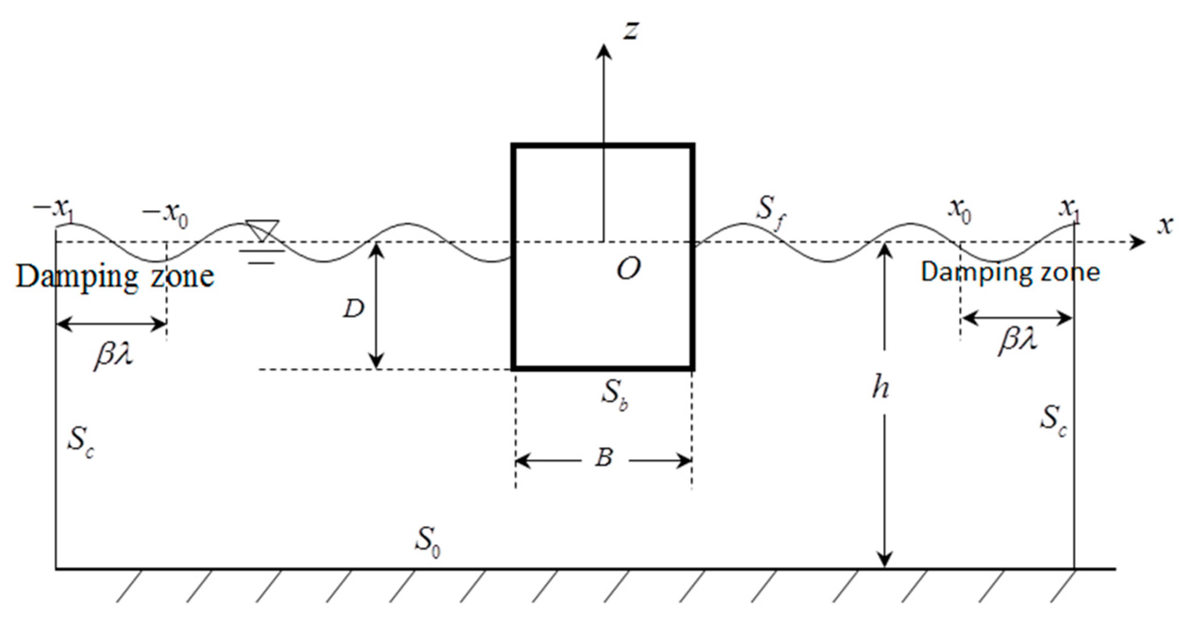
. All simulations were carried out in a fluid domain with the body located at the center and with the truncated boundaries placed at
including
damping zone in front of each truncated boundary. The nodes were initially equally distributed on the wetted surface of the body and local zone of the free surface with element size
. Away from the local zone, the element size increased gradually until the far end. Larger elements of equal size were employed on the truncated boundaries and not changed during mesh convergence study, because they were far away from the barge. The nodes on the seabed right below the barge were placed equally with size
throughout all the simulations. During the simulation, the wetted body surface was remeshed every time step, keeping the segment size as
. The whole free surface was remeshed and smoothed every five steps. The damping strength was set as 0.2 for all the cases. The damping applied was quite effective in absorbing the outgoing diffracted waves.
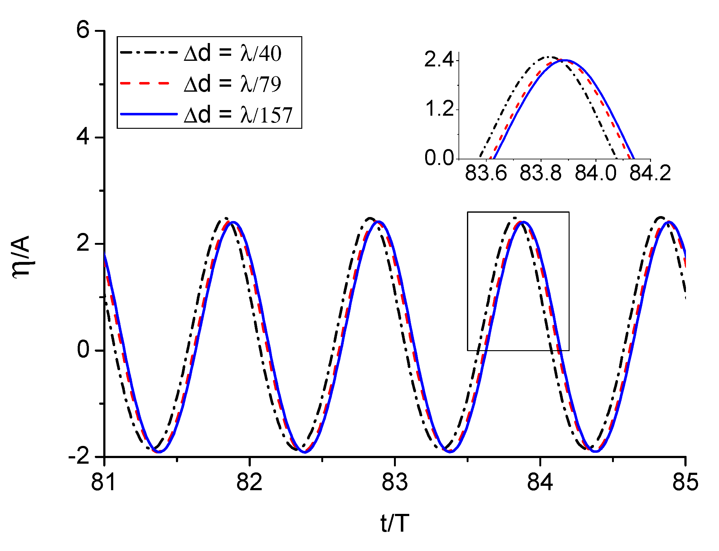
The convergence tests with respect to element size and time step were conducted based on the case of
, because its frequency lie in the middle of the frequency range. The mesh size only refers to the element on the wetted body surface and the local region of the free surface. Three different meshes and time steps were tested. The convergence tests against element size were studied through comparing results of wave runup histories and hydrodynamic loads on the barge, which are shown in
Figure 2 and
Figure 3, respectively. The time step was set as
for the calculations.
is the period of the incident wave. The forces are normalized by
. Unless otherwise specified, the vertical forces given exclude the contribution of initial buoyancy in all the following figures. Large differences, especially phase shifts, were observed between the results of
and
for both the wave runups and the hydrodynamic forces. The results for fine mesh
and finer mesh
were very close but with minor differences. It indicates that finer mesh
could guarantee convergent results. It is therefore the element size used for testing time step.
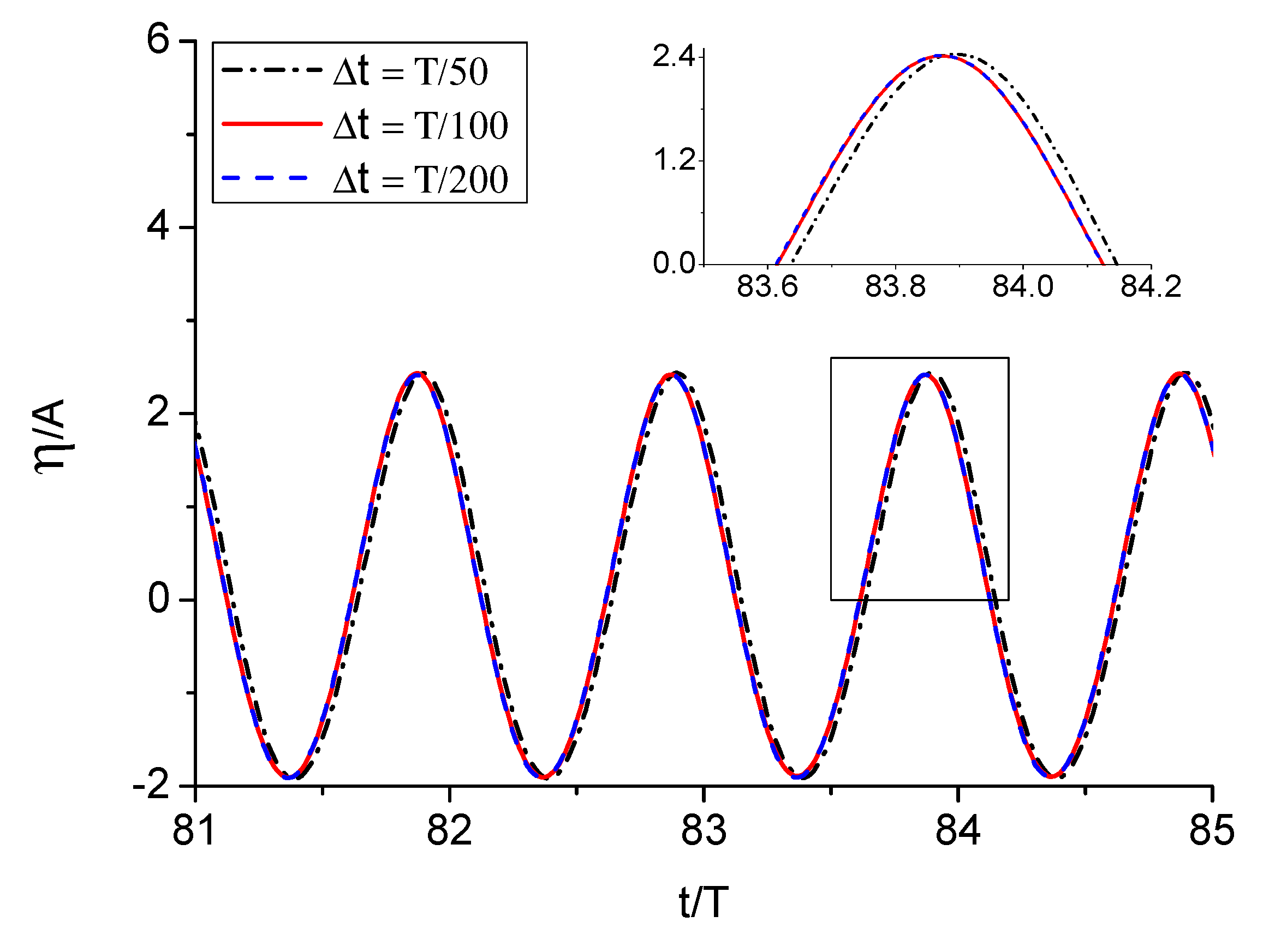
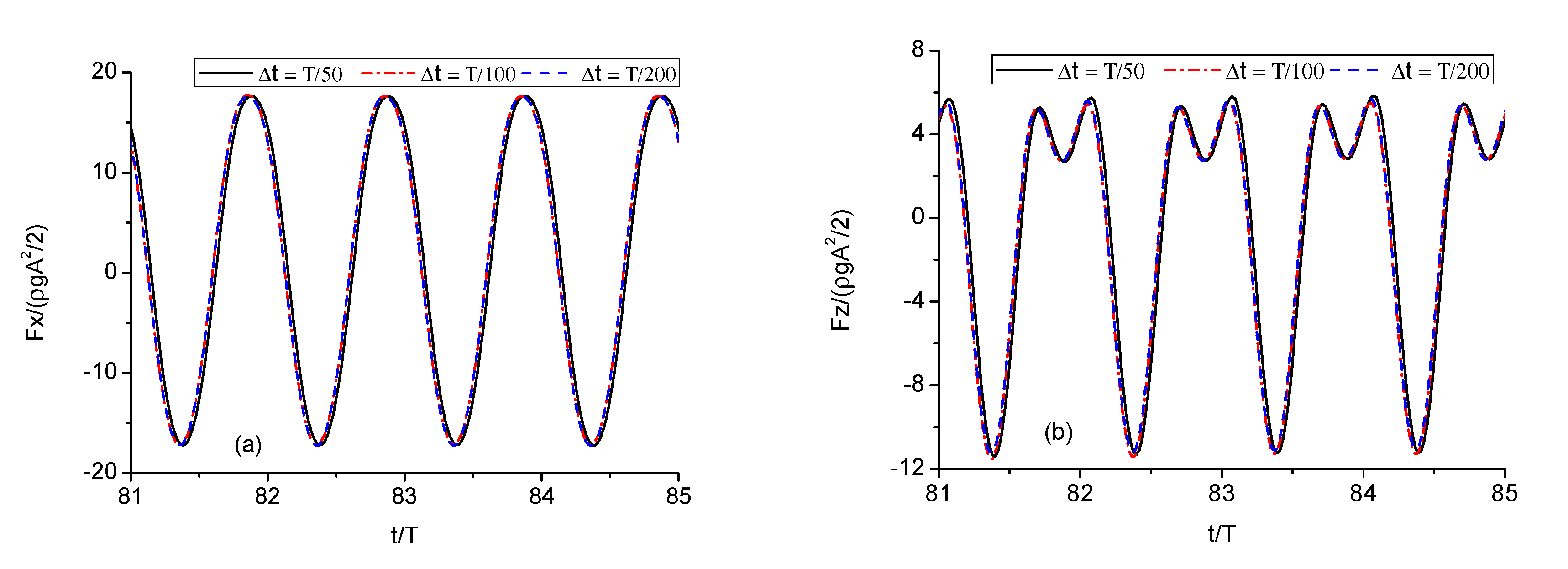
We then reran the simulations with
and
, and compared the corresponding wave runups and hydrodynamic forces on the barge in
Figure 4 and
Figure 5, respectively. We can see that the curves with
and
were virtually coincident with each other, which means that time step
was sufficient to guarantee the temporal convergence. The comparisons between results of different element size and time step suggest that
and
is a better combination for the present problem. The convergence study provides us reference values for choosing the time step and fundamental element size, and proper damping coefficients to obtain convergent results.
To verify the accuracy of the present numerical results, they were compared with published experimental [
35], analytical [
36], and other numerical results [
34,
37,
38]. The force components were determined through performing Fourier analysis on the steady state part of the force histories.
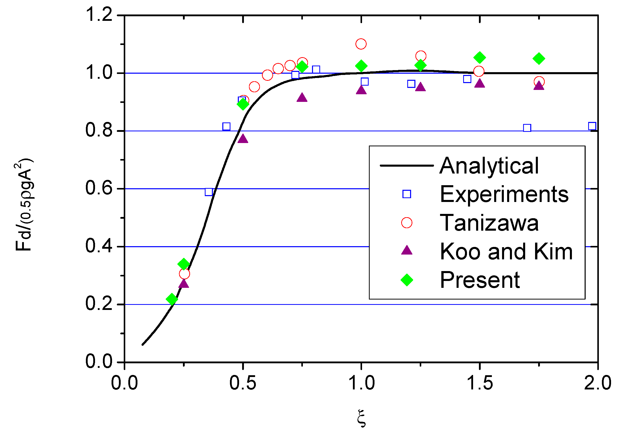
Figure 6 compares the calculated mean drift force
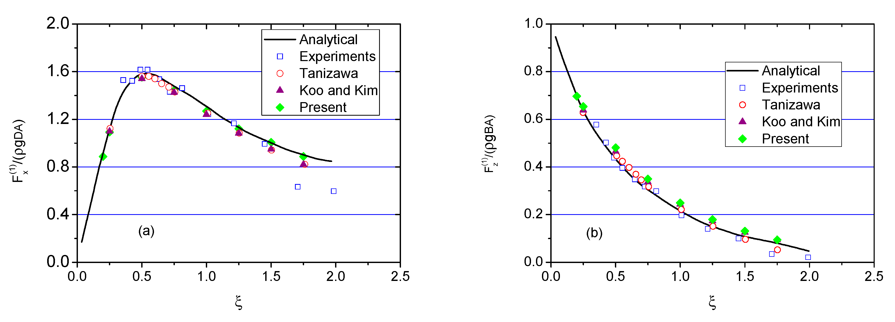
on the barge with other published results. Good agreements were shown in general, especially at the low-frequency range. The present results are generally larger than the results of Koo and Kim. Comparisons of the normalized first harmonic forces
on the barge are also made in
Figure 7 for both horizontal and vertical forces. The calculated first harmonic forces compare well with experimental, analytical, and numerical results. The comparisons indicate that the present numerical code is quite capable of capturing the higher harmonic forces and motions.
3.2. Pure Wave Diffraction by a Barge
Unless otherwise stated, the results presented later are nondimensionalized, which are based on the length scale , gravitational acceleration and the density of the fluid . The barge width is set as . The nondimensionalized time and frequency are respectively expressed as and accordingly. For convenience, the prime superscript is dropped. The forces are by nondimensionalized by . When analyzing the vertical forces, the contribution of static buoyancy is excluded.
The draught of the body was taken as
. Two sets of simulations associated with incident wave steepness
and
were conducted for a range of frequencies from
to
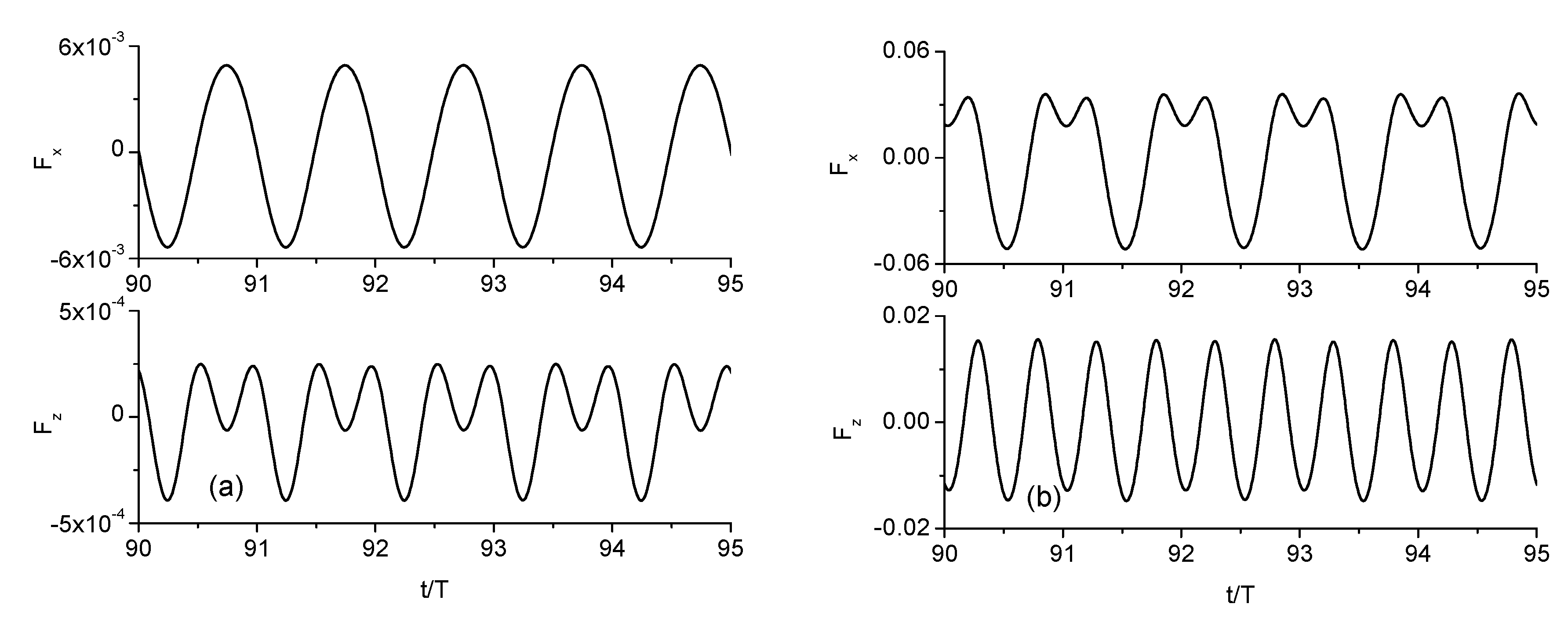
. The hydrodynamic forces on the barge became periodic after a short transient period for all the simulated cases. Examples of the force histories on the structure for lower frequency
and higher frequency
are shown in
Figure 8 and
Figure 9, respectively. The double peaks in the vertical components, especially for high frequency, indicate large higher harmonic forces.
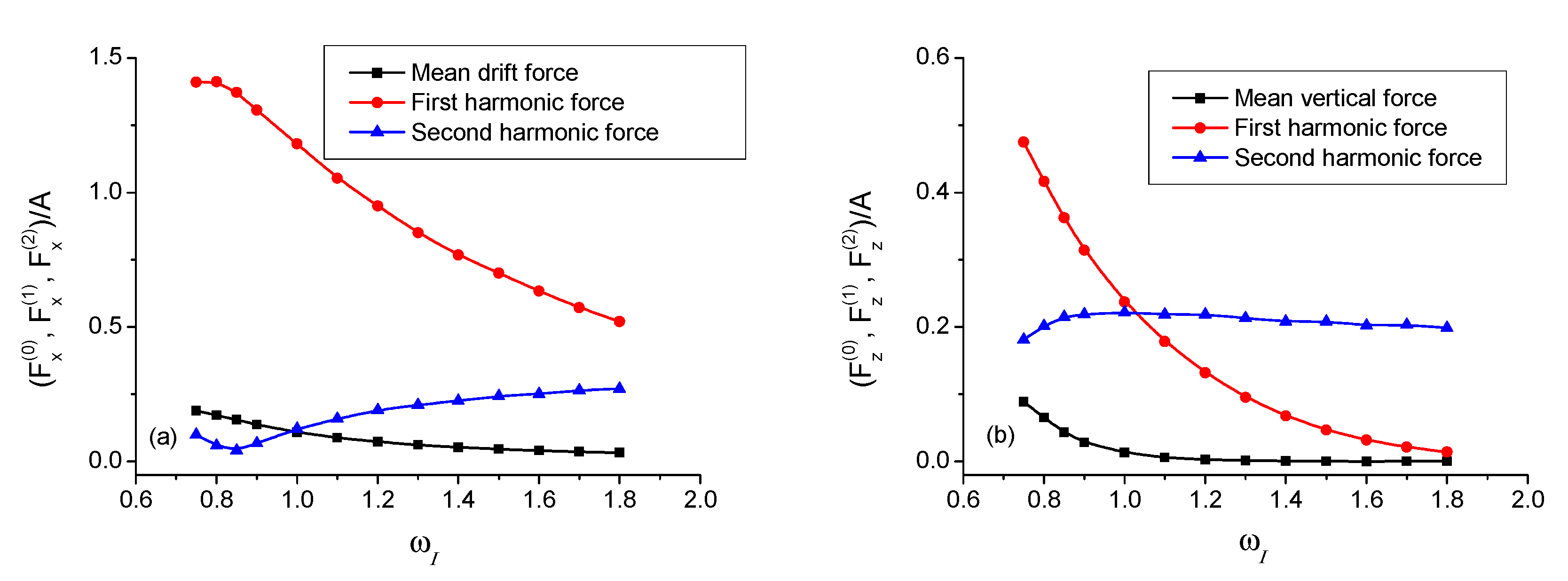
In order to distinguish the hydrodynamic force components, Fourier analysis was performed on the steady-state part of the force history.
Figure 10 presents the horizontal and vertical force components for
. As can be seen, the high-order harmonic forces cannot be neglected as they play an important role. The second harmonic vertical force in particular was actually larger than the first harmonic force after a certain frequency. The higher frequency means shorter waves. This phenomenon is also mentioned and explained in Koo and Kim [
34]. They pointed out that this phenomenon is related to a special nonlinear feature of second-order pressure field under standing waves.
3.3. Combined Wave Radiation and Diffraction by a Barge
There exist different types of problems such as a body in forced motion and under incoming wave at the same time, especially when the body has sway motion. In such a case, the wave interactions can be strengthened when the body is moving towards the incoming wave or weakened when it is moving away. The effect of the sway motion on wave diffraction will be analyzed in this subsection. The sway motion of the body was sinusoidal, and the amplitude of sway motion was the same as the incident wave amplitude. The draught of the body was set as . The incident wave steepness was set as 0.0283 in all the simulations.
3.3.1. Sway Motion with Same Frequency as Incident Wave
The interactions of the diffracted and radiated waves depend on their phase difference. The wave diffraction effect on the body can be changed as a result. The following study will investigate how the sway motion affects the hydrodynamic forces on the body with regard to different wave lengths. The wave length is determined through the dispersion relation.
Long wave diffraction and radiation by sway motion of the body was studied with
. The corresponding wavelength
was about 11.18.
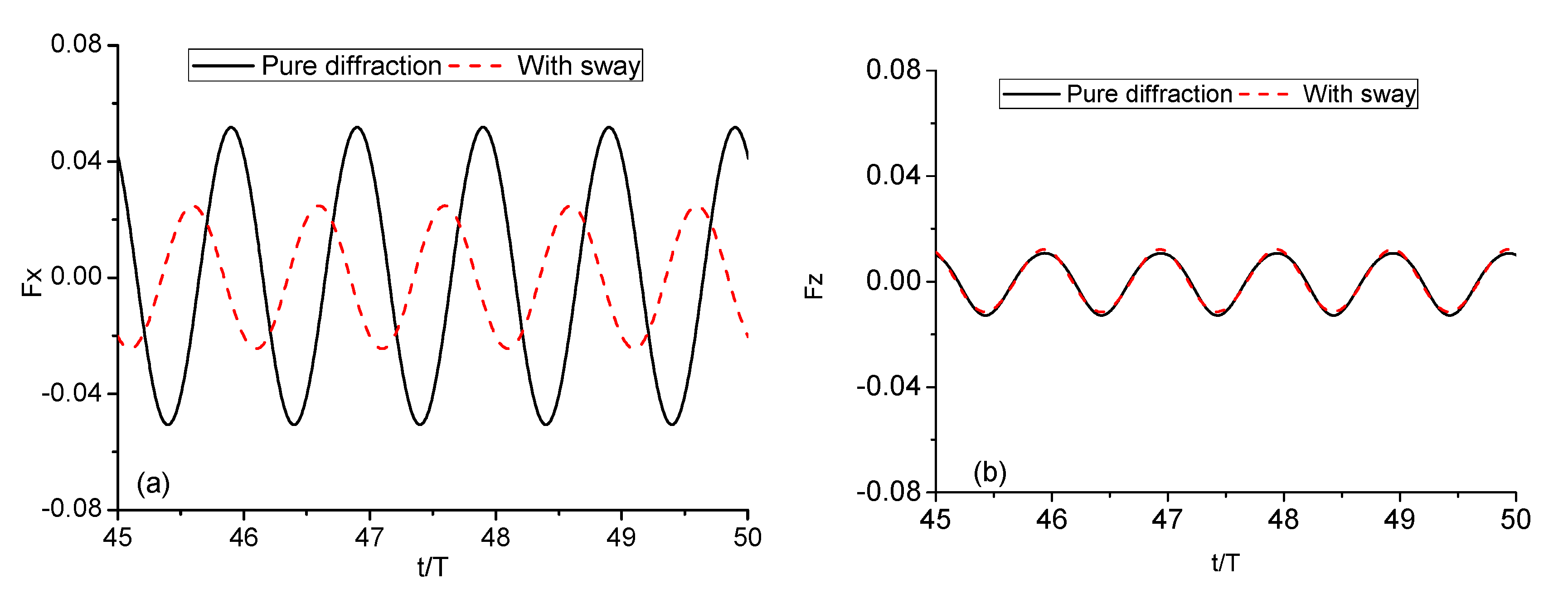
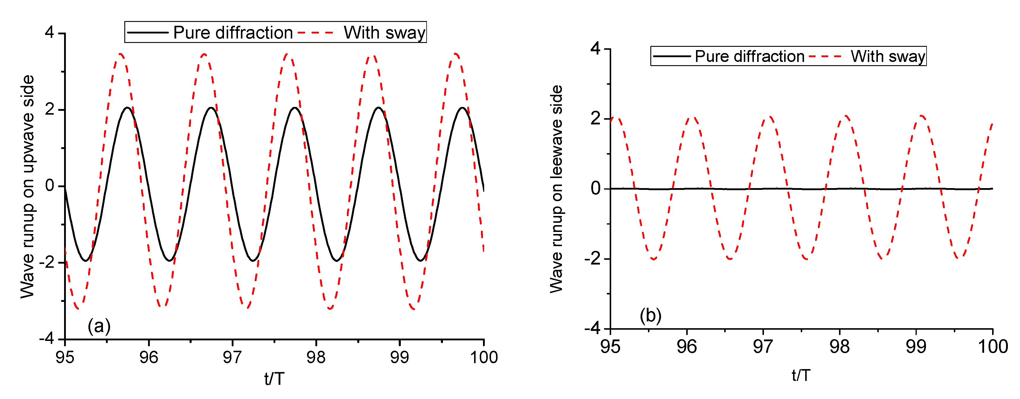
Figure 11 compares the wave runups on both sides of the body with and without sway motion. They are changed greatly as expected, especially on the leewave side. The body motion not only made the wave runup on the leewave side more than two times higher, but also changed the phase of it by 78°. The wave runup in all the figures is normalized by the amplitude of the incoming wave. The hydrodynamic forces on the body were affected accordingly as shown in
Figure 12. The sway motion actually decreased the hydrodynamic horizontal force on the body to a large extent. Specifically, the amplitude of the horizontal force with sway motion is only about a quarter of that of pure diffraction in this case. This is because the horizontal force resulted from the pressure difference between the two sides of the body and the sway motion made the difference smaller as shown in
Figure 11. There was also clear phase shift between the horizontal forces. The vertical force, which is associated with the pressure on the bottom of the body, was hardly affected.
The low wave frequency corresponded to long wave length relative to the body dimension, where the wave diffraction effect was of less significance. For intermediate wave with
, the diffraction and radiation problem was also studied. The comparisons of wave runups and hydrodynamic forces are given in
Figure 13 and
Figure 14, respectively. Similar conclusions can be drawn as in the long wave case. The sway motion of the body caused clear phase shifts of wave runups on both sides, especially the leewave side. These phase shifts led to phase difference between horizontal forces. The phase shifts between horizontal forces will be studied later. The sway motion makes the horizontal force half of that of pure diffraction in this case.
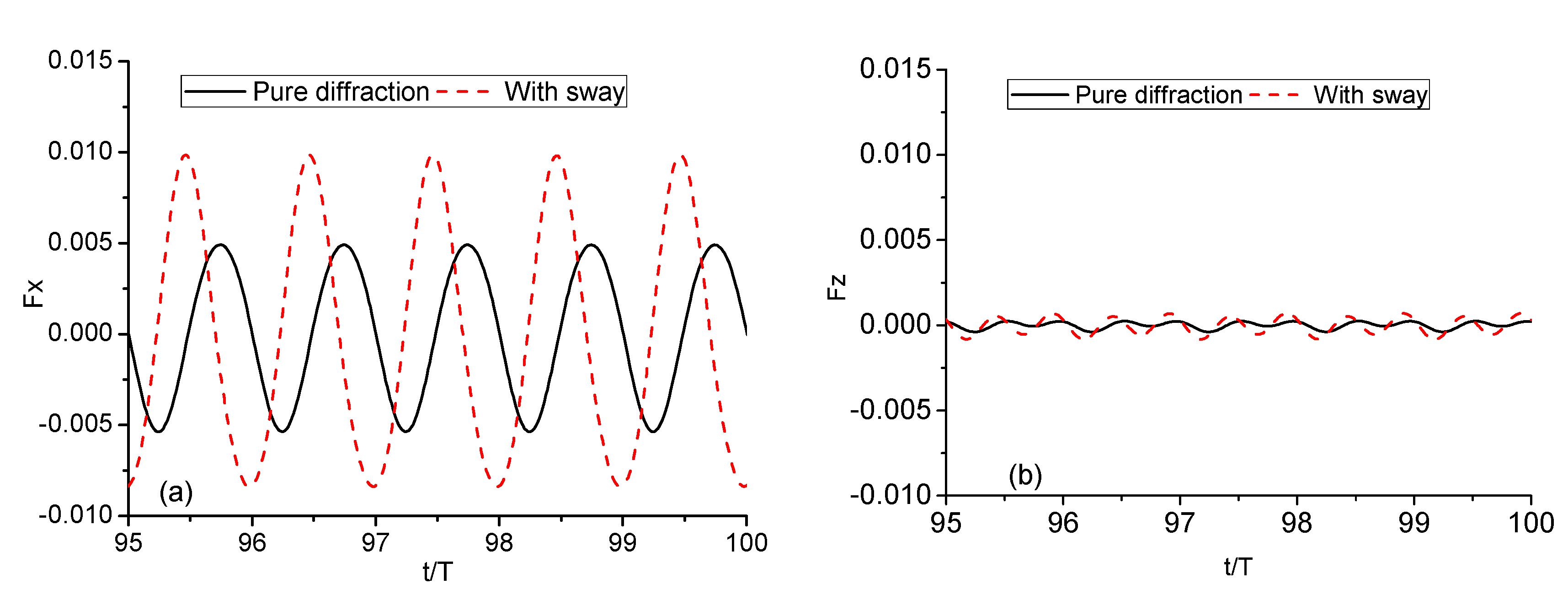
To test the effect of sway motion on short wave diffraction when the diffraction force is of significance, we considered the case of
,
. The comparison of wave runup on the body is presented in
Figure 15. When there was no body motion present, standing wave trains were formed in front of the body and nearly no wave behind. The superposition of the incident wave, diffracted wave, and the wave generated by sway motion made the wave runups on both sides of the body much larger. Meanwhile, the hydrodynamic load on the body was enlarged, as shown in
Figure 16. It is worth mentioning that in this case, the second harmonic vertical force was even larger than the first harmonic force, which is known from its spectral analysis in
Figure 17. Furthermore, the sway motion did not change its first harmonic component, but increased its second harmonic force considerably. This can be explained by the argument in Wu [
39]. The periodic sway motion itself will lead to vertical force with components of frequencies
Thus, it can significantly enlarge the steady and double frequency vertical force components.
Particularly, the sheltering effect behind the body, which is related to diffraction problem, was weakened by waves generated by sway motion. In terms of hydrodynamic forces, the horizontal force can be either enlarged or reduced with phase shift. From the above three cases, we notice that the change of horizontal force actually depended on the incident wave frequency. To get a better idea of how they are related, a series of cases with frequencies ranging from
to
were simulated. The amplitudes of horizontal forces associated with both pure diffraction and with sway motion cases were then calculated and compared. Using the horizontal forces of pure diffraction case as reference, the relative change of their amplitudes is given in
Figure 18. The relative change is presented against both wave frequency and wave length. Generally speaking, sway motion with low frequency reduced the overall horizontal force. The reducing effect decreased as the frequency increased until a critical frequency was reached where the amplitudes of horizontal forces for pure diffraction and with sway were equal. The critical frequency was about
. After that, the higher the frequency, the bigger the horizontal force increasing effect. As for the wave length, the relative change tendency was opposite to that against wave frequency.
As mentioned earlier, sway motion of the body can cause noticeable phase shifts of horizontal forces. The magnitudes of the shifts depend on the incident wave frequency, or rather the incident wave length.
Figure 19 gives the phase shifts against wave frequency and their dependency on wave length. The phase shift exceeded
in all the simulated cases. It reached its maximum value at
or
.
3.3.2. Sway Motion with Different Frequency from Incident Wave
The incident wave frequency was set as , partly because this frequency lies in the middle of the frequency range and partly because it is close to the critical frequency mentioned above. Next, we ran simulations of forced sway motion with frequency either higher or lower than the incident wave frequency. The frequency of sway motion is denoted as , and the period corresponds to the frequency of sway motion or incident wave, whichever is higher.
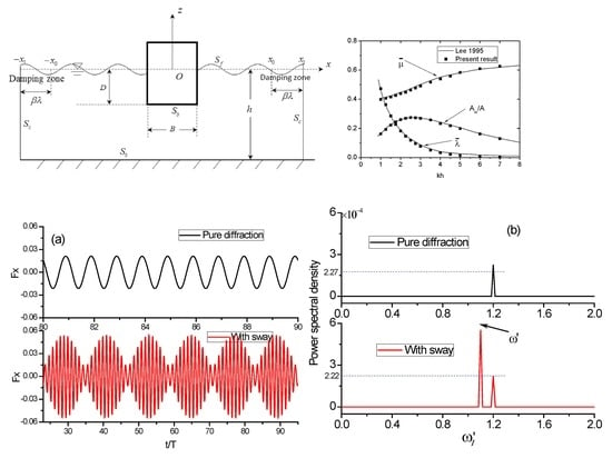
The cases with frequencies of sway motion lower than that of incident wave were first studied. Take
for instance, and the comparison of their horizontal force histories is shown in
Figure 20a. Clearly, the horizontal force with sway motion present had multiple frequencies. Therefore, the spectral analysis of them was performed and is compared in
Figure 20b. Two distinct frequencies, of which one relates to sway motion and the other relates to incident wave, were extracted. Moreover, the amplitude of horizontal force associated with sway motion was in fact larger than that of incident wave, which was hardly affected by the sway motion when comparing it to pure diffraction case. One may argue that there should be sum and difference frequency terms in the force as well. As a matter of fact, these terms were too small to show any significance, which can be seen in the close-up figure of spectral analysis
Figure 21.
The frequency
was much lower than the incident wave frequency. We now consider the case where
is close to
. Periodic envelope appeared on the horizontal force history as shown in
Figure 22a when
. The period of the envelope depended on the difference between
and
. The spectral analysis of the horizontal force was conducted and is provided in
Figure 22b. The same conclusion can be drawn as in the previous case. For the cases when
was higher than the incident wave frequency, the pattern of horizontal force on the body was quite different from that when
was lower than
.
Figure 23a shows the comparison of horizontal force histories of pure diffraction case and the case with sway motion
. It can be seen that the sway motion made the horizontal force on the body two times larger. The spectral analysis of them is given in
Figure 23b. It is interesting to see that only one single frequency associated with the sway motion existed, while the one with incident wave disappeared. More cases with
were then run to see the horizontal force spectral distribution in case the one with
was special.
Figure 24 gives the spectral analysis of horizontal force histories. It was confirmed that the frequency related to incident wave disappeared on the horizontal force spectra when
.
In terms of the magnitude of the horizontal force, slower sway motion of the body will always make the resultant force larger. That is because, on one hand, the effect of incident wave was hardly affected by sway motion, and on the other hand, the horizontal force itself resulting from the sway motion was bigger. It can be shown in
Figure 25, which gives the power spectral analysis of horizontal force histories with slower sway motion. When the frequency of sway motion was higher, there was no clear pattern.
4. Conclusions
This paper studies the combined wave radiation and diffraction by a single barge through fully nonlinear numerical simulations in the time domain. The associated initial boundary value problem for the velocity potential is solved using boundary element method together with a time stepping scheme. In order to keep the simulations running for a sufficiently long time, some special numerical treatments are also applied to the free surface, such as remeshing, smoothing, jet, and thin spray cutting. The findings in this paper are all based on the results obtained from potential flow theory.
In the cases for a single body under incident wave and with forced sway motion, the amplitude of sway motion is always kept the same as the incident wave amplitude and with a initial phase difference. Some of the interesting findings by spectral analysis of the hydrodynamic forces are:
- (1)
When the frequencies are also the same, sway motion will reduce the overall horizontal force when the frequency is lower than a critical frequency . After that, the higher the frequency, the bigger the horizontal force increasing effect.
- (2)
When the frequencies are different, the incident wave frequency is set as the critical frequency = 1.2. It has been found that for horizontal forces, only the frequency associated with sway motion is visible, while the one with incident wave frequency nearly disappears when .
- (3)
In terms of the magnitude of the horizontal force, sway motion of the body will always make the resultant force larger than that of pure diffraction case when within the simulated frequency range.
The above phenomena are expected to be valid in other configurations, such as a single body with different draught, even though the critical frequency may be different. It is worth mentioning that the interactions of diffracted and radiated waves also depend on the relative phase between the incident wave and forced sway motion. The effects of phase difference between them are not considered in this paper. The above conclusions are drawn based on the difference of .


