Article

Chromaticity Measurement Based on the Image Method and Its Application in Water Quality Detection

1
College of Computer Science and Technology, Huaibei Normal University, Anhui 235000, China
2
College of Environmental Science and Engineering, Tongji University, Shanghai 200092, China
*
Author to whom correspondence should be addressed.
Water 2019, 11(11), 2339; https://doi.org/10.3390/w11112339
Submission received: 4 October 2019 / Revised: 30 October 2019 / Accepted: 5 November 2019 / Published: 8 November 2019
(This article belongs to the Special Issue Monitoring, Modelling and Management of Water Quality)

Abstract

:
In order to measure the chromaticity of water and the content of dissolved matter more accurately, effectively, and cheaply, a chromaticity measurement system based on the image method was proposed and applied. The measurement system used the designed acquisition device and image processing software to obtain the Red-Green-Blue (RGB) values of the image and converted the color image from RGB color space to Hue-Saturation-Intensity (HSI) space to separate the chromaticity and brightness. According to the definition of chromaticity, the hue (H), saturation (S) values, and chromaticity of standard chromaticity solution images were fitted by a non-linear surface, and a three-dimensional chromaticity measurement model was established based on the H and S values of water images. For the measurement of a standard chromaticity solution, the proposed method has higher accuracy than spectrophotometry. For actual water sample measurements, there is no significant difference between the results of this method and the spectrophotometer method, which verified the validity of the method. In addition, the system was tried to measure the concentration of ammonia nitrogen, phosphate, and chloride in water with satisfactory results.

1. Introduction

Pollution can lead to changes in water color, especially in textile, leather, paper, pharmaceutical, printing, and dyeing industries [1,2]. Therefore, the pollution degree of water can be monitored by measuring the chromaticity of water [3]. Chromaticity is an index for the quantitative determination of the color of natural water or treated water, usually in the unit of degree (°). Natural water often shows light-yellow, light-brown, yellow-green, and other different colors. The cause of color is due to humus, organic or inorganic substances dissolved in water [4].
China’s current national standard method for water chromaticity measurement, “Water quality-determination of colority” (GB/T 11903-1989), is the platinum-cobalt colorimetric method and dilution multiple method [5]. Among them, platinum-cobalt colorimetric refers to the international standard “Clear liquids—Estimation of color by the platinum-cobalt scale—Part 1: Visual method” (ISO 6271-1-2004) [6]. At present, the international methods of measuring chromaticity include a spectrophotometer [7], a three-wavelength transmittance method [8], and a support vector machine regression prediction method [9]. In practical application, the platinum-cobalt colorimetric method has no obvious difference between 5 and 25, is not easy to judge, and its error is large. In the dilution multiple method, the response of different color tones to optic nerve stimulation is different because of the great difference of water sample tones, which creates personal subjectivity in discriminating. Finally, it is difficult for the dilution end point (colorless) to have a unified standard, and the final result will have a great error. Spectrophotometry is a method for the qualitative or quantitative analysis of the absorbance of light of a specific wavelength or a certain wavelength range. Because the substances in the solution have selectivity to absorb light, the absorbance and absorption spectra of different substances are different at different wavelengths, which make the solution present different colors [10]. Therefore, spectrophotometry can identify substances or measure their content according to the absorption spectra of different substances. A spectrophotometer is used to determine the chromaticity value of water samples by establishing the correlation between the absorbance value of a standard chromaticity solution at a characteristic wavelength or the peak area of the absorption spectrum and the chromaticity value. This method improves the accuracy of the water chromaticity measurement, but the price of a professional spectrophotometer is higher, and the characteristic wavelength of a chromaticity solution is no uniform standard, which inevitably leads to disagreements in measurement. The method of water chromaticity measurement based on three-wavelength transmittance is also a spectrophotometric method, which measures the true chromaticity of water quality by measuring the transmittance at three wavelengths. However, the selection of measuring points (three wavelengths) can be different because of different measurers, and the selection of measuring points will also be different, so the measurement results will also be different. The application of support vector machine regression to predict water chromaticity can obtain a high accuracy prediction model, but a large number of learning samples are needed. A large number of training samples will increase the workload of the measurement, leading to low measurement efficiency.
Excessive ammonia nitrogen in the water environment will cause much harm to water bodies, such as reducing the dissolved oxygen concentration in water and accelerating water eutrophication [11]. Phosphate can disrupt the ecological balance of the water environment by promoting the proliferation of algae (called eutrophication) and the consequent consumption of dissolved oxygen (when algae decay) [12]. Chloride dissolved in water is toxic and can cause dizziness, nausea, dyspnea, and even death [13]. Therefore, the measurement of ammonia nitrogen, phosphate, and chloride content in water is very important. At present, the methods for the determination of the properties and contents of organic matter in water are ultraviolet visible spectroscopy [14], mobile mass spectrometry [15], linear regression and artificial neural network [16], the sensor method [17], the trace element tracing method [18,19] and the potentiometric titration method [20]. Among them, ultraviolet visible spectroscopy, mobile mass spectrometry, and the sensor method need professional analytical instruments that come with high measurement cost; the linear regression and artificial neural network method needs a large number of training data to ensure the accuracy of the measurement, and the measurement efficiency is low; the trace element tracing method and potentiometric titration method have low operability and need professional technicians to operate in water quality detection.
Cameras have been widely used in various fields. In physics, a digital camera is used to study the trajectory of the water jet, the outline of the suspension chain, and the defocus figure reflected on the mirror of different shapes [21]. Digital cameras are also used to describe the color and physical properties of soil samples [22]. In chemistry, Red-Green-Blue (RGB) values can be converted into other color spaces, and then, the conversion functions of soil organic carbon and iron can be derived by using these color spaces to measure their concentrations quickly and accurately [23]. Moreover, a digital camera was used to determine iron and residual chlorine in water using N,N-diethylphenylenediamine [24]. In Maputo Bay, Mozambique, digital cameras are also used to measure the suspended sediment concentration, which prompted discussion on the possibility of using digital photography to measure the suspended sediment concentration in other coastal waters [25]. The development of using digital cameras within the field of water quality detection can provide a new measurement method for water quality detection. In order to measure water chromaticity more accurately, quickly, and cheaply, a water chromaticity measurement system based on the image method is proposed. The proposed chromaticity measurement system based on a digital camera can be used to measure the content of ammonia nitrogen, phosphate, and chloride in water. And it can simplify the design of measuring instruments and improve the accuracy of measurement, which is of great significance in water quality detection.
The designed chromaticity measurement system uses an image acquisition device to collect the image of a standard chromaticity solution. The solution image captured by the camera is the color image of the standard chromaticity solution. The color can be separated into brightness and chromaticity [26]. Chromaticity is the property of color that does not include brightness. It reflects the hue and saturation of color. The image processing software designed in this paper actually converts the color solution image from RGB color space to Hue-Saturation-Intensity (his) space. Then, the brightness can be separated. Finally, a three-dimensional relationship model between hue (H), saturation (S), and chromaticity and a standard curve between H, S-standard-deviation (△HS), and solute concentration are established for the measurement of water chromaticity and solute content.

2. Materials and Methods

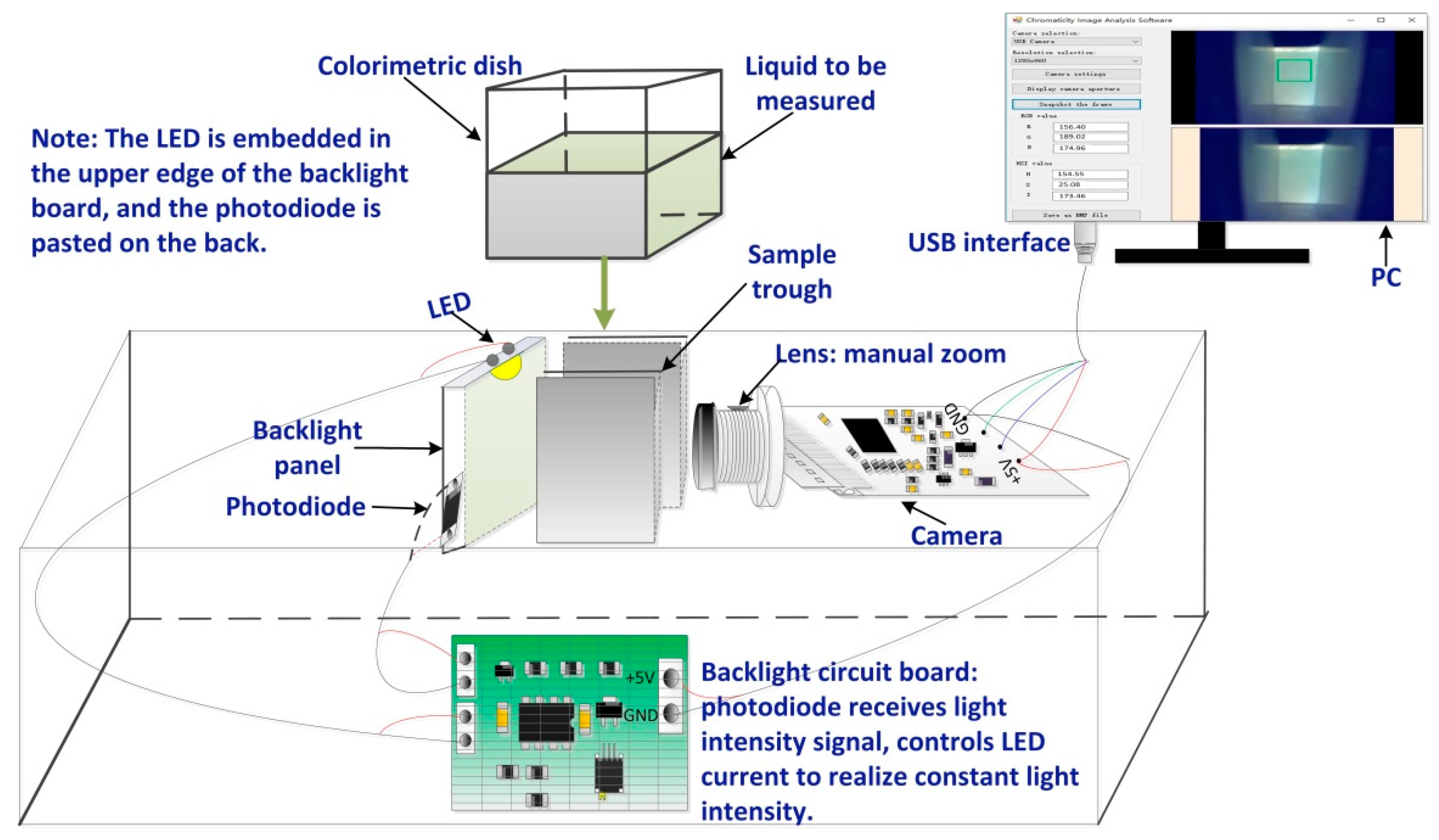
2.1. Design of a Measurement System Structure

The water chromaticity measurement system was designed to include a water image acquisition device and image processing software, as shown in Figure 1.
The acquisition device is used to collect a liquid image, which is processed by the image processing software to get RGB and HSI values and to achieve chromaticity separation.

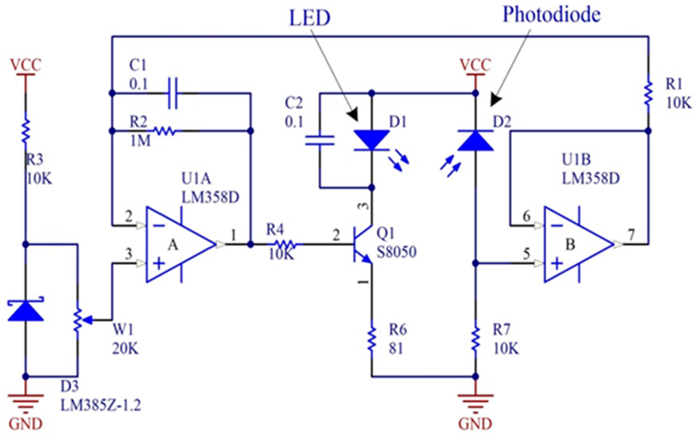
2.1.1. Image Acquisition Device

The water image acquisition device consists of a high-color-rendering LED, a backlight panel, a constant light source circuit, a digital camera, and a sealed box. The light color of the LED is warm white, the color temperature is in the range of 2600–4500 K, the corresponding luminous intensity is 9.5 cd(lm), and the forward voltage is 2.9–3.5 V.
Adding a backlight panel between the light source and the solution can bring uniformity to the light and improve the image quality, avoid the uneven brightness of the collected image, and affect the color value of the image. The constant light source circuit makes the light intensity of the light source constant, which is a closed-loop control circuit, as shown in Figure 2. Within the circuit, D2 detects the light intensity of D1 and generates a voltage signal, which is buffered by U1B, then controls the working current of D1 to stabilize the light intensity. Although the design is relatively simple, the effect of constant light intensity is very good [27].
The digital camera used is a JD-300 digital camera produced by Shenzhou Jiuding Technology Co., Ltd. in Beijing, China, and its structure is shown in Figure 3.
The camera can adjust brightness, contrast, hue, saturation, and white balance, and use manual adjustments for exposure and zoom. When using this camera to acquire chromaticity images, it is necessary to ensure that the various parameters are constant and adjust the exposure and focus to the appropriate size.

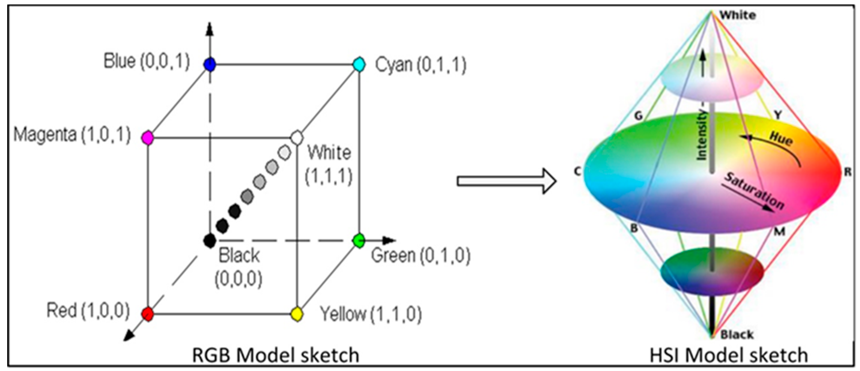
2.1.2. Software Design

The image processing software designed in the measurement system is developed on the platform of Visual Studio 2012 based on the open source camera development toolkit and C# language. The software digitalizes the collected water image, that is, to get the pixel value of the image.
The edge of the liquid image captured by the camera will be geometrically distorted, and the RGB value of the image will be affected when the image is digitized. In order to avoid the effect of edge distortion on the accuracy of data, the RGB values of 400 pixels in the central region of the image are selected, and then the average RGB values of these pixels are obtained. The image was then transformed from RGB color space to HSI color space to separate the chromaticity and brightness by the image processing software. The conversion algorithm is as follows.
Given the RGB value of the acquired water image, the H component can be obtained by Formula (1):
H = { θ , ( B G ) 360 θ , ( B > G ) ,
in which,
θ   =   arccos { 1 2 [ ( R G ) + ( R B ) ] [ ( R G ) 2 + ( R G ) ( G B ) ] 1 3 } .
The saturation component S is derived from Formula (3):
S = 1 3 ( R + G + B ) [ min ( R , G , B ) ] ,
and the final intensity component Intensity (I) is derived from Formula (4):
I = 1 3 ( R + G + B ) .
The color space conversion is shown in Figure 4.
The software designed can control the exposure, contrast, hue, saturation, and other properties of the camera. It is necessary to adjust and fix the camera attributes when measuring a water image. The designed software interface and camera property control are shown in Figure 5.
Figure 5b shows the main interface of the image processing software, which contains buttons such as camera settings and image capture. The camera setting button controls the properties of the camera. Figure 5a shows the camera parameters of this experiment. The function of the image capture button is to get the RGB and HSI values of the current image. Combining the image processing software and the image acquisition device, it can be used to measure the chromaticity of water.

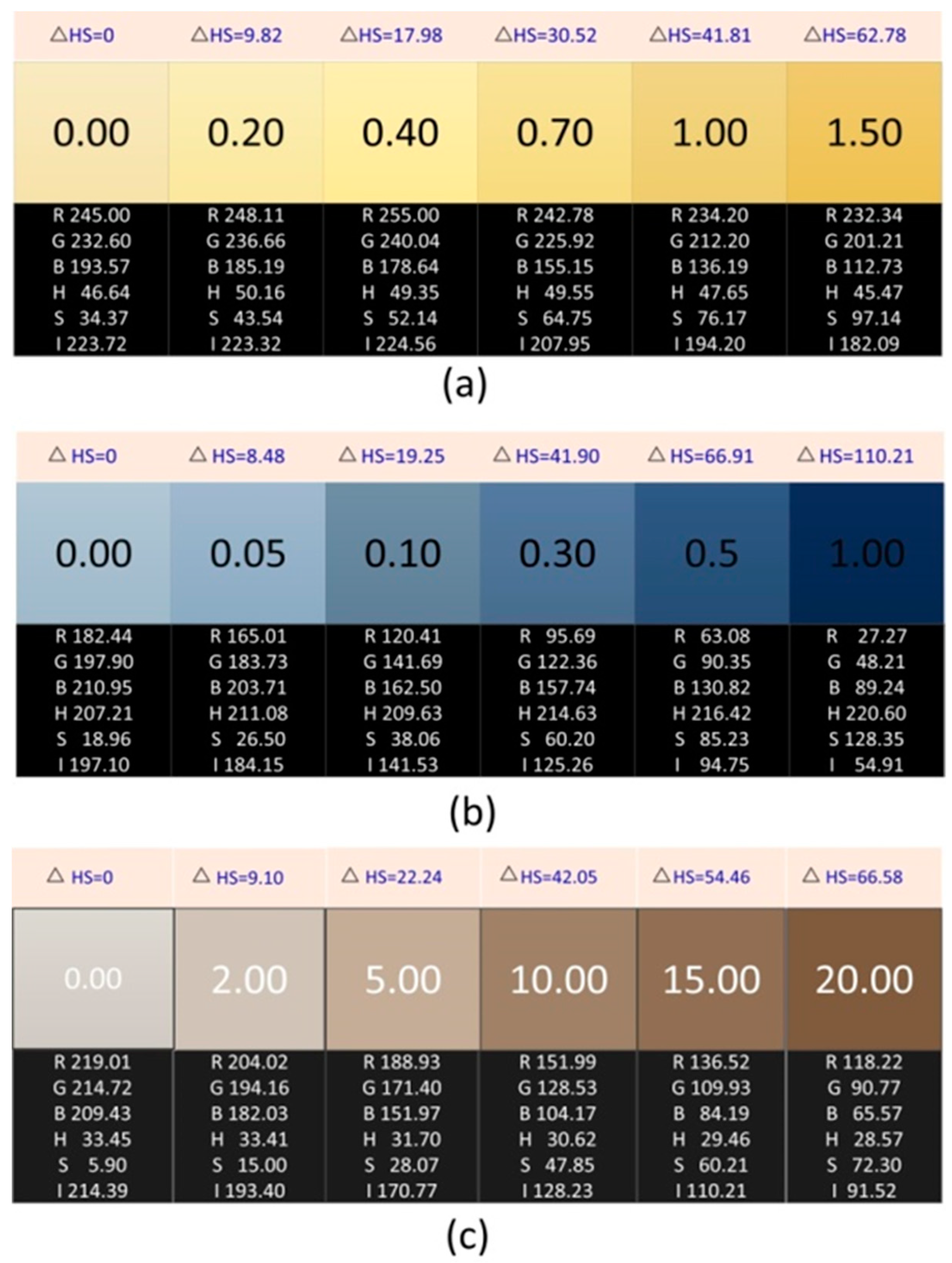
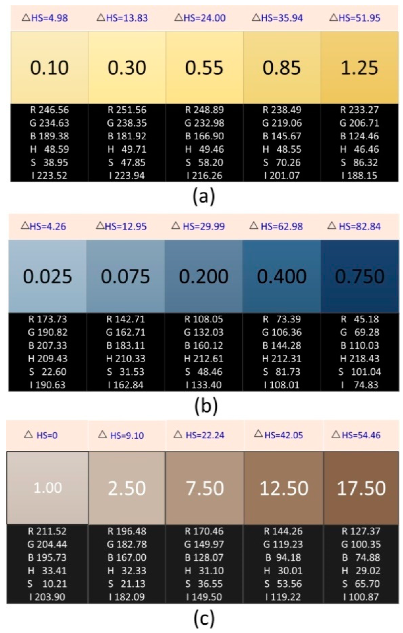
2.2. Preparation and Information Acquisition of Chromaticity Standard Solution

In this design, 1.245 g of potassium chloroplatinate (MESCO Chemical Co., Ltd, Tianjin, China) and 1.000 g of cobalt chloride (Jingshiji mall, Changsha, China) were dissolved in 200 mL hydrochloric acid (Mingcheng Chemical Co., Ltd, Qidong, China) with a concentration of 6 mol/L, and then diluted to 1000 mL with deionized water. The standard platinum-cobalt chromaticity solution with a chromaticity of 500 was prepared. Thirty standard solutions of different chromaticity in the range of 0–500 were obtained by diluting the 500-degree chromaticity solution according to a gradient. The standard chromaticity solution was poured into the colorimetric dish (size is 34 × 15 × 43 mm3, and the optical path is 30 mm) and then put into the sample trough of the designed chromaticity measurement system to measure. The RGB and HSI values of the chromaticity image are obtained by the designed chromaticity measurement system. Some image data are shown in Figure 6.
With the increase of solution chromaticity, the RGB and HSI values of corresponding images also change, reflecting the corresponding relationship between RGB and HSI values and chromaticity. The obtained HS value is fitted with the standard chromaticity, and the no-linear relationship between the chromaticity and the HS value is established. The chromaticity value of the solution to be measured is calculated according to the fitting expression.

2.3. Preparation and Data Acquisition of Standard Solutions of Ammonia Nitrogen, Phosphate, and Chloride

The 1000 mg/L ammonia-nitrogen standard solution: ammonium chloride 3.819 g (NH4Cl, superior purity, China Jiehui Chemical Reagent, Wuhan, China) dried at 100 °C was dissolved in a small amount of deionized water. It was then transferred into a 1000 mL capacity bottle and diluted to 1000 mL by adding deionized water. The mixture was uniform. The standard ammonia-nitrogen solutions with concentrations of 0 mg/L, 0.2 mg/L, 0.4 mg/L, 0.7 mg/L, 1.0 mg/L, and 1.5 mg/L were prepared by further dilution. Ammonia nitrogen was detected by Nessler’s reagent color reaction, such as Formulas (5) and (6):
HgI 2 + 2 KI K 2 HgI 4 ,
2 K 2 HgI 4 + 3 KOH + NH 3 NH 2 Hg 2 OI + 7 KI + 2 H 2 O ( yellow-brown   complex ) ,
the designed chromaticity measurement system is used to obtain image information of the complex solution, as shown in Figure 7a.
The 500 mg/L phosphorus standard solution: potassium dihydrogen phosphate was dried at 110 °C for four hours (KH2PO4, superior purity, Shanghai Reagent Plant, Shanghai, China). Then, 5.444 g was accurately weighed. It was dissolved in a small amount of deionized water, transferred to a 500 mL capacity bottle, and diluted to 500 mL calibration with deionized water. The standard phosphorus solutions with concentration of 0 mg/L, 0.05 mg/L, 0.1 mg/L, 0.3 mg/L, 0.5 mg/L, and 1.0 mg/L were prepared by further dilution. Under acidic conditions, the active phosphate reacts with ammonium molybdate to form yellowish phosphomolybdenum yellow, which is reduced to blue phosphomolybdenum blue by stannous chloride, such as Formulas (7) and (8):
H 3 PO 4 + 12 ( NH 4 ) 2 MoO 4 + 21 HNO 3 = ( NH 4 ) 3 H 4 [ P ( Mo 2 O 7 ) 6 ] + 21 NH 4 NO 3 + 10 H 2 O ,
( NH 4 ) 3 H 4 [ P ( Mo 2 O 7 ) 6 ] + 2 SnCl 2 + 4 HCL = ( NH 4 ) 2 H 4 [ ( Mo 2 O 7 ) 5 ] + 2 SnCl 4 + 2 H 2 O ,
The image information of the generated blue solution is obtained by the chromaticity measurement system proposed in this design, as shown in Figure 7b.
A chloride standard solution (1000 mg/L) was purchased from Zhongke Beijing Instrument Consumables Standard Materials Store of China. The chloride standard solution was diluted to 0 mg/L, 2 mg/L, 5 mg/L, 10 mg/L, 15 mg/L, and 20 mg/L. In neutral or weak alkaline solution, when potassium chromate is used as the indicator and silver nitrate is used to titrate chloride, because the solubility of silver chloride is less than that of chromate, after the chloride ion is completely precipitated, the chromium ion is precipitated in the form of silver chromate, and a brick red substance is produced. The color of the red precipitate is proportional to the chloride content. The precipitation titration reactions are Formulas (9) and (10):
Ag + + Cl AgCl ( white ) ,
2 Ag + + CrO 4 2 Ag 2 CrO 4 ( brick   red ) .
The brick red precipitate solution is placed in the designed chromaticity measurement system to obtain the image information of the solution, as shown in Figure 7c.
Figure 7a shows the image information and HS standard deviation of different concentrations of ammonia nitrogen, and Figure 7b,c show the image information and HS standard deviation of different concentrations of phosphate and chloride, respectively. Among them, △HS is the standard deviation between the HS value of each dissolved matter image and the HS value of the blank sample image, which is calculated by Formula (11):
Δ HS = ( H H 0 ) 2 + ( S S 0 ) 2 .

3. Results

The HS value of standard chromaticity solution was used to fit the non-linear relationship with the chromaticity, and a three-dimensional chromaticity measurement model based on HS was established. The model was applied to the measurement of the standard chromaticity solution to verify the accuracy of the measurement method. When comparing the proposed method with spectrophotometry, the accuracy of this method is higher than that of spectrophotometry for the standard chromaticity solution; for the actual water sample measurement, there is no significant difference between the measurement result of this method and that of spectrophotometry.

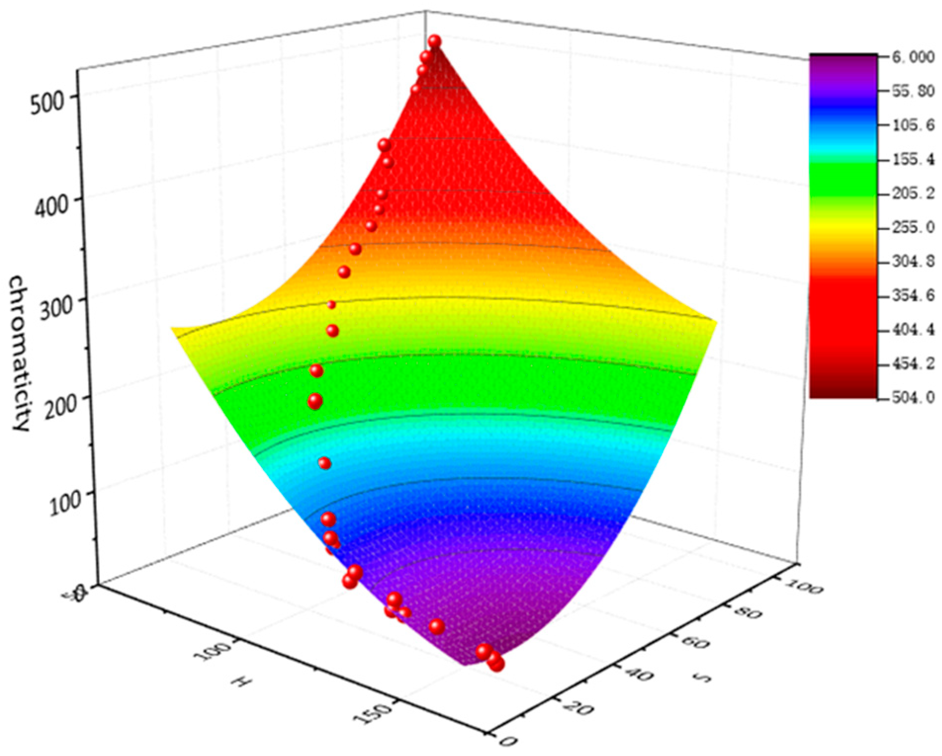
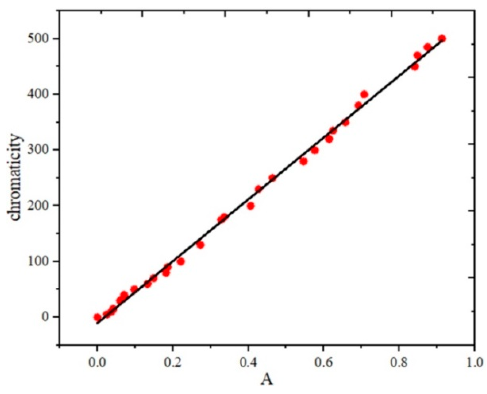
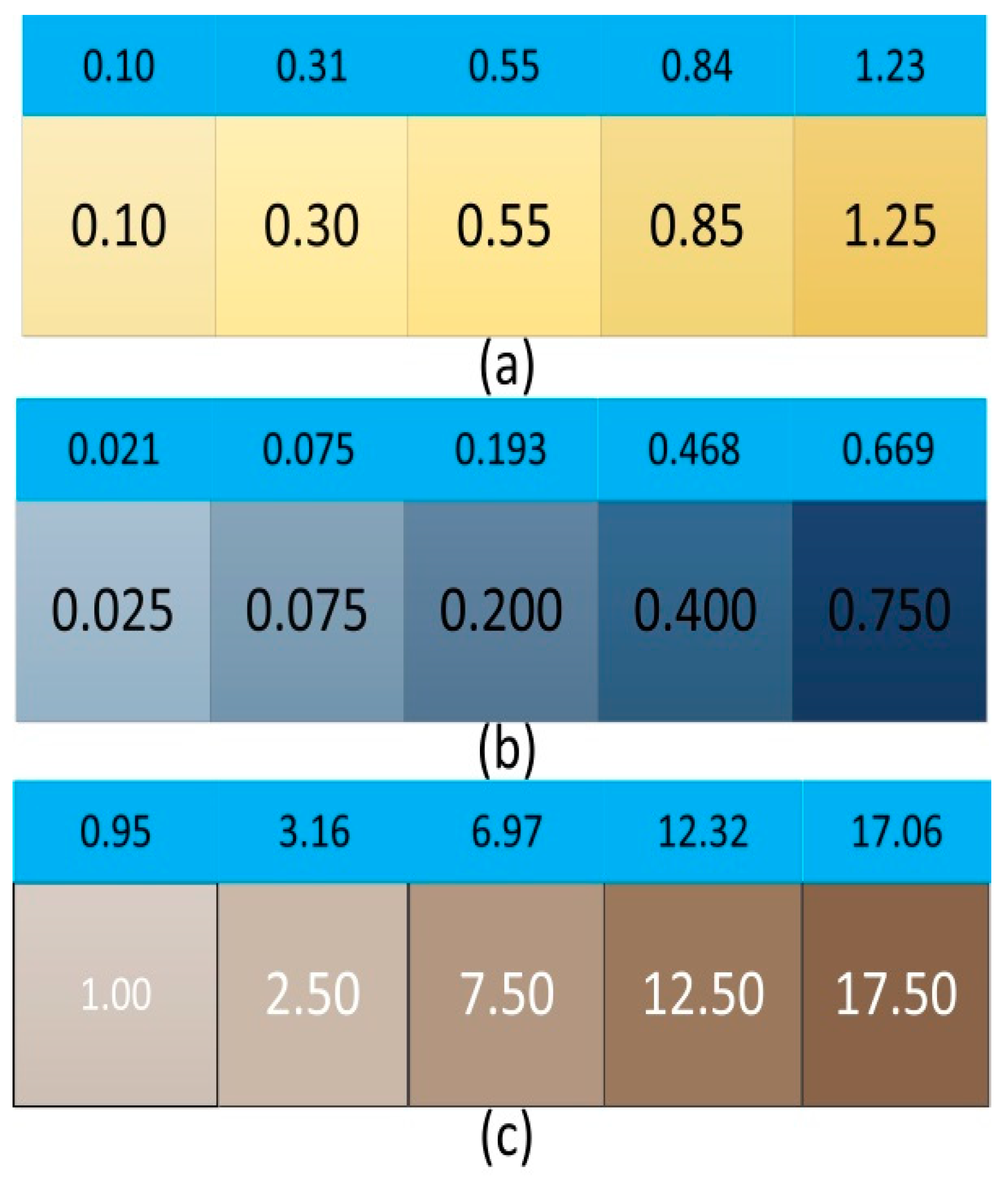
3.1. Fitting Results

The color includes chromaticity and brightness, and the chromaticity of the color is obtained by separating the brightness of the color. After separating the brightness, the color image only contains H and S values, which correspond to the chromaticity, so the relationship model between HS and chromaticity can be established. The data fitting software Origin 8.0 (OriginLab, Northampton, MA, USA) is used to establish surface fitting with H and S as X and Y axes and chromaticity as Z axes, respectively. The fitting results are shown in Figure 8.
The chromaticity data in the graph are all distributed on the surface, which is the fitting surface of HS and chromaticity. The expression is as shown in Formula (12), and the fitting degree is as high as 0.99845:
Z = 634.4507 6.73548 x 2.61133 y + 0.01882 x 2 + 0.04596 y 2 .
In Formula (12), x represents the input value H, y is the input value S, and Z is the chromaticity of the corresponding solution. By substituting the HS value of the solution to be measured into the expression, the chromaticity of the solution to be measured can be calculated.

3.2. Measurement Results

In order to verify the accuracy of the designed chromaticity measurement system, the model was used to measure the standard chromaticity solution with known chromaticity. The results of measurement and comparison are shown in Table 1.
From Table 1, the results of the proposed method are close to the standard chromaticity solution, and the error is small. Therefore, the designed chromaticity measurement system can effectively measure the chromaticity of water.

3.3. Contrast Experiment of Standard Chromaticity Solution

In order to verify the accuracy of the proposed method, the chromaticity measurement model is compared with the latest spectrophotometric method.
In this comparative experiment, a 721 G visible spectrophotometer produced by Shanghai Instrument and Electrical Analysis Instrument Co., Ltd., was used as the comparative object.
When using a spectrophotometer to measure the chromaticity of the solution, it is necessary to determine the characteristic wavelength of the solution to be measured at first. Because of the absorption wave of natural water reaches its peak at 380 nm, and the wavelength of the spectrophotometer is set to 380 nm. A 3 cm colorimetric dish was selected to hold the solution to be measured, and a higher accuracy could be obtained. The wavelength of the spectrophotometer was adjusted to 380 nm. The standard chromaticity solution was put into the spectrophotometer to measure the absorbance. Finally, the standard curve of absorbance (A) and chromaticity was established, as shown in Figure 9.
The fitting expression is Formula (13), and the fitting degree is as high as 0.99741:
y = 555.2641 x 10.33369 .
According to the fitting curve of absorbance and chromaticity, the measurement results of spectrophotometry for the standard chromaticity solution can be obtained. The results are compared with the proposed chromaticity measurement system. Some of the comparison results are as shown in Table 2.
Table 2 shows that the mean deviation and standard deviation of the standard chromaticity solution measured by spectrophotometry are larger than those proposed in this paper, and the proposed method has higher accuracy. The comparison results of the two methods are shown in Figure 10.
In Figure 10, samples one to five represent 20°, 55°, 150°, 265°, and 430° standard chromaticity solutions. The measurement curve of the proposed method almost coincides with the standard chromaticity curve, and the measurement error fluctuates around 0. The deviation between the spectrophotometric measurement curve and the standard chromaticity curve is relatively large, and the fluctuation range of the measurement error curve is larger than that of the method proposed in this design. Therefore, the accuracy of the proposed method is higher than that of the spectrophotometric method.

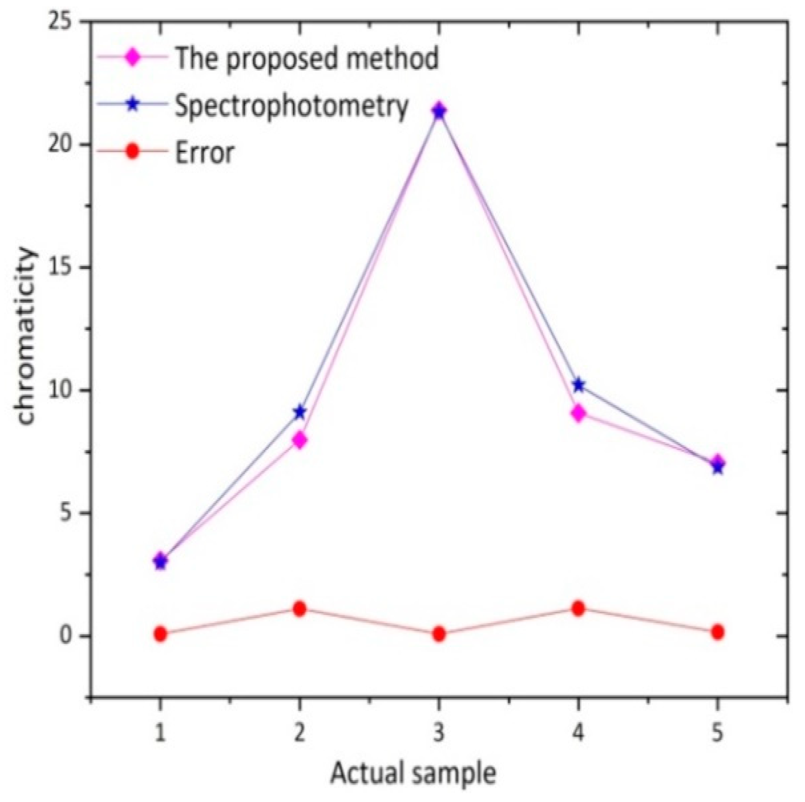
3.4. Contrast Experiment of Actual Water Sample

The local tap water (Sample 1), lake water (Sample 2 to 4), and river water (Sample 5) were taken as the actual samples of the validation experiment, and the proposed method and spectrophotometric measurement were used, respectively. First, the HS value and absorbance of actual water samples were measured by the designed chromaticity measuring device and 721 G visible spectrophotometer. Some image data acquisition results are shown in Figure 11.
The HS and A (absorbance) values of the actual water samples were substituted into the chromaticity measurement model and the fitting expression of the spectrophotometry, and the results of the two methods for the actual water samples were obtained as shown in Table 3.
A comparison of the two measurement methods for an actual water sample is shown in Figure 12, and the results are tested by an independent sample t-test. The test results are shown in Table 4.
In Figure 12, the measurement results of the proposed method have the same trend as those of spectrophotometry, and the error is small. In Table 4, the independent sample t-test of the two methods shows that the p value is 0.93 (>0.05), which shows that there is no significant difference between the two methods. The validity of the design in the actual water sample measurement is verified.

4. Discussion and Further Application

4.1. Camera Combined with Image Processing Technology instead of Photoelectric Instrument to Detect Colorable Substances in Water

The main purpose of water quality detection is to detect and analyze the composition, nature, and content of pollutants in water to ensure the safety of water quality [28]. In order to detect water quality more effectively and conveniently, digital camera and image processing technology can be used instead of traditional photoelectric instruments to measure the content of colored organic matter in water. Most of the digital cameras use Complementary Metal-Oxide-Semiconductor (CMOS) sensors. As a semiconductor element, the CMOS photosensitive element is used to record the light changes, which is mainly composed of silicon and germanium. Their advantages are the high integration, low power consumption, and low cost. Each pixel of the camera is equivalent to a photoelectric detection element. The signal processing unit integrated by the camera can replace the digital to analog conversion circuit and the signal processing circuit of the photoelectric detection instrument. Using a camera and the HS color component of a picture to measure water quality can avoid the design of the photoelectric detection circuit, signal processing circuit, digital to analog conversion circuit, and display circuit. In theory, the detection of trace components based on color reaction can be realized by using digital camera and image processing technology.

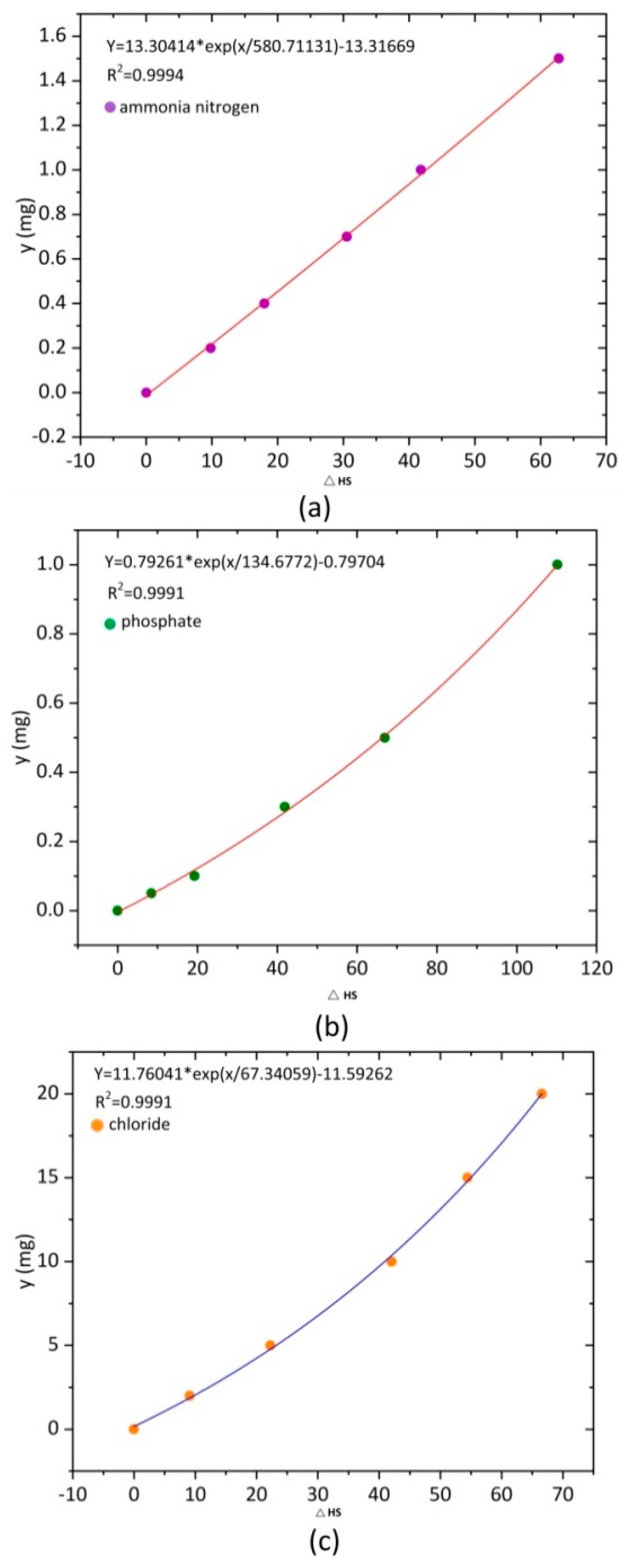
4.2. Application in the Detection of Ammonia Nitrogen, Phosphate, and Chloride in Water

Generally, the polluted water contains solutes such as ammonia nitrogen, chloride, phosphate, and sulfide [29]. The proposed chromaticity measurement system was applied to the measurement of dissolved substances such as ammonia nitrogen, phosphate, and chloride in water for water quality detection, and the standard curve of HS standard deviation and dissolved substance content in water was established.
The RGB and HSI values of the pictures of ammonia nitrogen, phosphate, and chloride solutions with different concentrations were obtained by using the designed chromaticity measurement system. The standard deviation of HS for each concentration of solute and blank solution was obtained, as shown in Figure 7. The standard deviation of HS was fitted with the concentration of solute in water, and the standard curve was established. The standard curve expression and the fitted results are shown in Figure 13.
Figure 13a–c shows the fitting curves of ammonia nitrogen, phosphate, and chloride concentration, respectively. The fitting curve is used to measure the standard organic compound solution and test the accuracy of the fitting curve. The different concentrations of ammonia nitrogen, phosphate, and chloride standard solutions were taken, respectively, and used in the chromaticity measurement system to obtain image information of the standard solution, as shown in Figure 14.
Figure 14a–c shows the image information of different concentrations of ammonia nitrogen, phosphate, and chloride solution. The established concentration measurement curve was used to measure the standard organic compound solution, and the measurement results are shown in Figure 15.
The errors between the measurement results and the standard concentration of solute are shown in Table 5.
Table 5 shows that the average difference between ammonia nitrogen concentration measured by the fitting curve and standard concentration is 0.008, phosphate concentration is 0.031, and chloride concentration is 0.372. The error between the fitted concentration of solute and the corresponding standard concentration is small, which indicates that the designed color measurement system can be applied to the measurement of solute content in water and has higher accuracy.

4.3. Comparison of Water Quality Detection Methods based on Camera Image

In recent years, a water quality detection method based on the image method has been proposed, mainly based on the ratio and reflection of three primary colors.
M. white et al. [30] found that linear relations between both the ratio of red/green digital output (O/P) values (at a particular camera exposure) and the difference in green–red digital camera O/P were found with the mineral suspended solids (MSS) concentration. A good comparison was also found between the ratios of red/green upwelling light measured with the camera and a conventional irradiance sensor. However, semi-empirical or analytical relationships between camera O/P and the inherent optical properties of the water could not be established. Then, Goddijn [31] proposed a method to measure the content of yellow substance and chlorophyll in water by using a digital camera. The RGB value of an underwater picture was obtained by using a digital camera and the linear relationship between colored dissolved organic matter and the R/B camera output. The log–log relationship between chlorophyll and the G/B camera output was established. These two methods are based on the RGB ratio of the water image.
Based on the water reflection model, a linear relationship between water column radiation and water concentration is established [32] for water quality detection. Based on a similar principle, Thomas Leeuw et al. [33] put forward an App called Hydro Color. The program first obtains three images with cameras, which are used to calculate the red, green, and blue wide band remote sensing reflection. Finally, it estimates the water reflection coefficient (the reflection coefficient can be reversed to estimate the concentration of absorbed and scattered substances in water) and turbidity value according to the remote sensing reflection. These two methods are based on the RGB reflection of water images.
From RGB to HSI color space, a water quality detection method based on the HSI component of a water image was proposed, and a sealed image acquisition device with a constant light source was designed to acquire water image, which avoids the interference of external environment on image information and ensures the accuracy of the measurement. Compared with the traditional optical instrument measurement method, the proposed method has higher accuracy and is effectively applied to the measurement of actual water samples. Compared with the above methods, the proposed method is based on the chromaticity method, which eliminates the influence of brightness, and can be used for the measurement of almost all colored substances in water. Due to a constant light source and closed measurement environment, the proposed method has high stability and practicability and is not affected by the external environment, which can be used as a perfect water quality detection instrument. In the future, we need to study various color components of water, obtain more measurement values, establish an effective and perfect water quality measurement model and apply the method to medicine, food, and other fields.

5. Conclusions

Using a digital camera to acquire a solution image to measure the chromaticity and solute content in water has the advantages of high accuracy, low cost, and strong practicability. It provides a new method for water quality detection. The RGB and HSI values of solution images can be obtained by the designed image acquisition system and processing software. The chromaticity measurement model based on H and S values was established to measure the chromaticity of water and compare it with spectrophotometry. For the measurement of a standard chromaticity solution, the proposed method has higher accuracy than spectrophotometry. For the actual water sample measurement, there is no significant difference between the results of this method and the spectrophotometer method. A curve based on the H and S standard deviation was established. The fitting results accorded with the exponential law, and the fitting degree was more than 0.999. It can be used to measure the solute content in water. This method can be widely used in almost all the determination of trace components based on color reaction, which can replace spectrophotometry without the wavelength setting and is easy to operate. The method is not only suitable for direct color analysis of natural water, but also suitable for wastewater detection. However, wastewater samples must be pretreating, such as digestion, distillation, precipitation, etc., and is preferred to separate and remove interferences.

Author Contributions

Conceptualization, P.C. and S.L.; data curation, S.L.; formal analysis, Y.Z.; funding acquisition, H.G.; investigation, W.Z.; methodology, Y.Z.; project administration, S.L.; resources, P.C. and Y.Z.; software, P.C.; supervision, H.G.; validation, W.Z. and H.G.; visualization, P.C.; writing—original draft, P.C.; Writing—review and editing, S.L.

Funding

This research was funded by the National Natural Science Foundation of China (No. 61671434) and the Natural Science Fund for Colleges and Universities of Anhui Province (No. KJ2017ZD32).

Acknowledgments

The authors would like to thank Hongwen Gao for their assistance on this project.

Conflicts of Interest

The authors declare no conflict of interest.

References

  1. Xiao, Y.H.; Räike, A.; Hartikainen, H.; Vähätalo, A.V. Iron as a source of color in river waters. Sci. Total Environ. 2015, 536, 914–923. [Google Scholar] [CrossRef] [PubMed]
  2. Breneman, I.V.J.; Blasinski, H.; Farrell, J. The Color of Water: Using Underwater Photography to Estimate Water Quality. Proc. SPIE 2014, 90230R. [Google Scholar] [CrossRef]
  3. Wang, Y.; Kidger, T.E.; Tatsuno, K. The water colority measurement based on HSV chromaticity. Proc. SPIE 2014, 1002124. [Google Scholar] [CrossRef]
  4. Jin, X.; Xiang, C.; Qi, D. A on Industrial Water Treatment Technology, 3rd ed.; Chemical and Chemical Press: Beijing, China, 2003; pp. 37–38. [Google Scholar]
  5. Grabas, M. Organic matter removal from meat processing wastewater using moving bed biofilm reactors. Environ. Prot. Eng. 2000, 26, 55–62. [Google Scholar]
  6. ISO. Clear Liquids—Estimation of Colour by the Platinum-Cobalt Scale—Part 1: Visual Method, ISO 6271-1-2004; ISO: Geneva, Switzerland, 2004. [Google Scholar]
  7. Wang, A. Study on the determination of water colority. Environ. Monit. China 2000, 16, 37–40. [Google Scholar]
  8. Zhao, X.; Shen, W. Standard for water color determination based on three-wavelength luminous transmittance. Chin. J. Environ. Eng. 2013, 7, 4766–4772. [Google Scholar]
  9. Funt, B.; Xiong, W. Estimating Illumination Chromaticity via Support Vector Regression. In Proceedings of the Color and Imaging Conference, Scottsdale, AZ, USA, 1 January 2004. [Google Scholar]
  10. Zeng, F.; Luo, X. Determination of the colority of water samples by spectrophotometry. Ind. Water Treat. 2006, 26, 69. [Google Scholar]
  11. Peng, P.; Huang, H.; Ren, H.; Ma, H.; Lin, Y.; Geng, J. Exogenous N-acyl homoserine lactones facilitate microbial adhesion of high ammonia nitrogen wastewater on biocarrier surfaces. Sci. Total Environ. 2018, 624, 1013–1022. [Google Scholar] [CrossRef]
  12. Camargo, J.A.; Alonso, Á.; Puente, M.D.L. Eutrophication downstream from small reservoirs in Mountain Rivers of Central Spain. Water Res. 2005, 39, 3376–3384. [Google Scholar] [CrossRef]
  13. Bian, X.; Fan, J.; Duan, H. Measurement of cyanogen chloride in drinking water with isonicotinic acid-pyrazolone spectrophotometry. Mod. Prev. Med. 2009, 36, 3328–3329. [Google Scholar]
  14. Li, G.; Tong, Y.; Li, J. Research on ultraviolet-visible absorption spectrum preprocessing for water quality contamination detection. Optik 2018, 164, 277–288. [Google Scholar] [CrossRef]
  15. Brkić, B.; Giannoukos, S.; Taylor, S. Mobile mass spectrometry for water quality monitoring of organic species present in nuclear waste ponds. Anal. Methods UK 2018, 10, 5827–5833. [Google Scholar] [CrossRef] [Green Version]
  16. Charulatha, G.; Srinivasalu, S.; Maheswari, O.U. Evaluation of ground water quality contaminants using linear regression and artificial neural network models. Arab. J. Geosci. 2017, 10, 128. [Google Scholar] [CrossRef]
  17. Mori, Y.; Hopmans, J.W.; Mortensen, A.P. MultiFunctional Heat Pulse Probe for the Simultaneous Measurement of Soil Water Content, Solute Concentration, and Heat Transport Parameters. Vadose. Zone J. 2003, 2, 561–571. [Google Scholar] [CrossRef]
  18. Domask, W.G.; Kobe, K.A. Mercurimetric Determination of Chlorides and Water-Soluble Chlorohydrins. Anal. Chem. 2002, 24, 989–991. [Google Scholar] [CrossRef]
  19. Kónya, J.; Nagy, N.M. Determination of water-soluble phosphate content of soil using heterogeneous exchange reaction with 32 P radioactive tracer. Soil Till. Res. 2015, 150, 171–179. [Google Scholar] [CrossRef]
  20. Bogoslovskiy, V.V.; Chernova, N.S. Potentiometric determination of the content of water-soluble organic amides. Fibre Chem. 2007, 39, 73–75. [Google Scholar] [CrossRef]
  21. Gil, S.; Reisin, H.D.; Rodríguez, E.E. Using a digital camera as a measuring device. Am. J. Phys. 2006, 74, 768–775. [Google Scholar] [CrossRef]
  22. Levin, N.; Benâ Dor, E.; Singer, A. A digital camera as a tool to measure colour indices and related properties of sandy soils in semi-arid environments. Int. J. Remote Sens. 2005, 26, 5475–5492. [Google Scholar] [CrossRef]
  23. Rossel, R.V.; Fouad, Y.; Walter, C. Using a digital camera to measure soil organic carbon and iron contents. Biosyst. Eng. 2008, 100, 149–159. [Google Scholar] [CrossRef]
  24. Suzuki, Y.; Endo, M.; Jin, J.; Iwase, K.; Iwatsuki, M. Tristimulus colorimetry using a digital still camera and its application to determination of iron and residual chlorine in water samples. Anal. Sci. 2006, 22, 411–414. [Google Scholar] [CrossRef] [PubMed]
  25. Hoguane, A.M.; Green, C.L.; Bowers, D.G.; Nordez, S. A note on using a digital camera to measure suspended sediment load in maputo bay, mozambique. Remote Sens. Lett. 2012, 3, 259–266. [Google Scholar] [CrossRef]
  26. Tang, B.; Sapiro, G.; Caselles, V. Color image enhancement via chromaticity diffusion. IEEE Trans. Image Process. 2001, 10, 701–707. [Google Scholar] [CrossRef] [PubMed]
  27. Cao, P.; Zhao, W.; Liu, S.; Shi, L.; Gao, H. Using a Digital Camera Combined with Fitting Algorithm and T-S Fuzzy Neural Network to Determine the Turbidity in Water. IEEE Access 2019, 7, 83589–83599. [Google Scholar] [CrossRef]
  28. Bao, X.; Liu, S.; Song, W. Using a PC camera to determine the concentration of Nitrite, Ammonia Nitrogen, Sulfide, Phosphate, and Copper in Water. Anal. Methods UK 2018. [Google Scholar] [CrossRef]
  29. Scatena, F.N. Drinking water quality. Drink. Water For. 2000, 2000, 7. [Google Scholar]
  30. White, M.; Feighery, L.; Bowers, D.; O’Riain, G.; Bowyer, P. Using digital cameras for river plume and water quality measurements. Int. J. Remote Sens. 2005, 26, 4405–4419. [Google Scholar] [CrossRef]
  31. Goddijn, L.M.; White, M. Using a digital camera for water quality measurements in Galway Bay. Estuar. Coast. Shelf. Sci. 2006, 66, 429–436. [Google Scholar] [CrossRef]
  32. San, L.H.; Jafri, M.M.; Abdullah, K. Aerial Photogrammetry Method for Water Quality Monitoring Using Digital Camera. Open Environ. Sci. 2009, 3, 20–25. [Google Scholar] [CrossRef] [Green Version]
  33. Leeuw, T.; Boss, E. The HydroColor App: Above Water Measurements of Remote Sensing Reflectance and Turbidity Using a Smartphone Camera. Sensors 2018, 18, 256. [Google Scholar] [CrossRef]
Figure 1. Structure of a water chromaticity measurement system.
Water 11 02339 g001
Figure 2. Constant light intensity circuit diagram.
Water 11 02339 g002
Figure 3. Camera printed circuit board details.
Water 11 02339 g003
Figure 4. Diagram of the color space model from Red-Green-Blue (RGB) to Hue-Saturation-Intensity (HSI).
Water 11 02339 g004
Figure 5. Software interface and camera property settings. (a) is the camera parameters of this experiment. (b) is the main interface of the image processing software.
Water 11 02339 g005
Figure 6. Partial image data and the corresponding color components.
Water 11 02339 g006
Figure 7. Image information of solutions with different concentrations. (a) is the image information of the yellow-brown complex solution. (b) is the image information of the blue phosphomolybdenum blue solution. (c) is the image information of the brick red complex solution.
Water 11 02339 g007
Figure 8. Fitting results of hue (H) and saturation (S) values and chromaticity.
Water 11 02339 g008
Figure 9. Fitting curves of absorption and chromaticity.
Water 11 02339 g009
Figure 10. Comparisons of two measurement methods.
Water 11 02339 g010
Figure 11. Partial actual water sample data.
Water 11 02339 g011
Figure 12. Comparison of measuring results for actual water samples.
Water 11 02339 g012
Figure 13. Fitting curve and result of soluble content in water. (a) is the fitting curves of ammonia nitrogen. (b) is the fitting curves of phosphate. (c) is the fitting curves of chloride.
Water 11 02339 g013
Figure 14. Image information of standard organic compound solution. (a) is the image information of different concentrations of ammonia nitrogen solution. (b) is the image information of different concentrations of phosphate solution. (c) is the image information of different concentrations of chloride solution.
Water 11 02339 g014
Figure 15. Measurement results of standard solution for ammonia nitrogen, phosphate, and chloride. (a) is the measurement results of standard solution for ammonia nitrogen. (b) is the measurement results of standard solution for phosphate. (c) is the measurement results of standard solution for chloride.
Water 11 02339 g015
Table 1. Measurements of the standard chromaticity solutions.
Chromaticity (°)
Standard solution2055150265430
HS surface fitting18.0750.00151.63264.54456.72
Error1.935.001.630.4626.72
Table 2. Comparison of measurement results by two methods.
MethodsStandard Solution (°)Mean Error (°)Std Dev (°)
Standard solution2055150265430
The proposed method18.0750.00151.63264.54456.727.155.46
Spectrophotometry10.7760.74156.25270.63453.8710.145.51
Table 3. Comparison of measurement results by two methods.
MethodsSample 1Sample 2Sample 3Sample 4Sample 5
The Proposed Method (°)3.087.9921.409.087.04
Spectrophotometry (°)3.009.1021.3210.216.88
Error (°)0.081.110.081.130.16
Table 4. Comparison of measurement results by two methods.
MethodsChromaticity (°)tp
The Proposed Method9.72 ± 3.09−0.090.93
Spectrophotometry10.10 ± 3.06
Table 5. Comparison of fitted concentration and standard concentration.
Solutes Maximum Error (mg/L)Minimum Error (mg/L)Mean Deviation (mg/L)
Ammonia nitrogen0.020.000.008
Phosphate0.0810.0000.031
Chloride0.660.050.372

