A 3D Reconstruction Pipeline of Urban Drainage Pipes Based on MultiviewImage Matching Using Low-Cost Panoramic Video Cameras


Abstract
1. Introduction
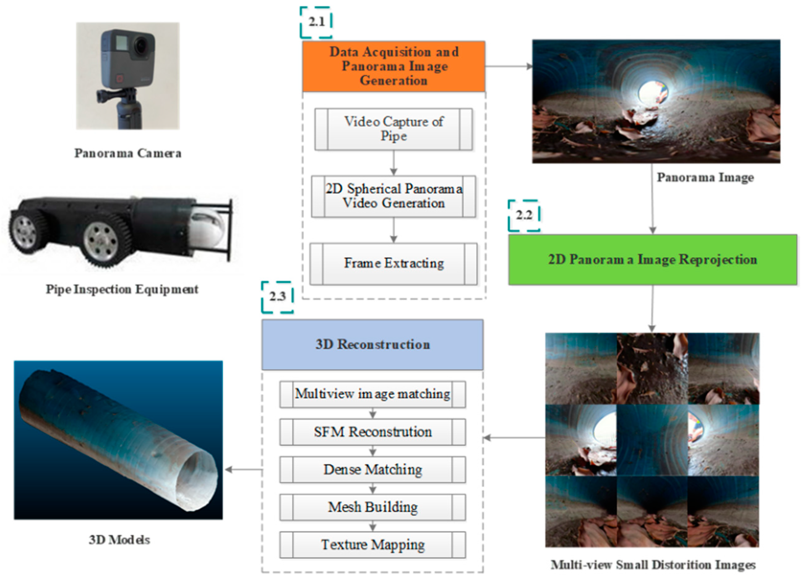
2. Methodology
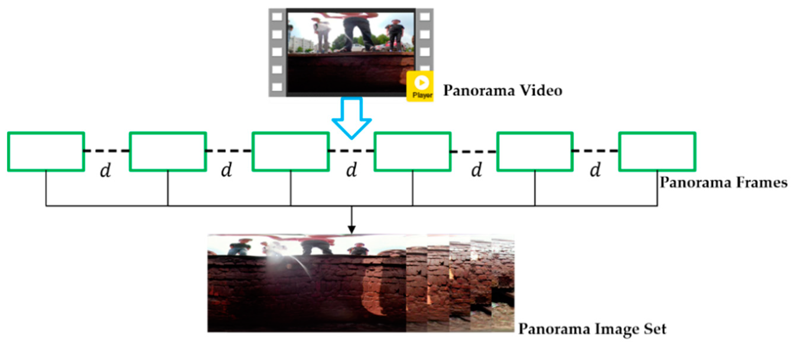
2.1. Pipe Panoramic Video Capture and Frames Extraction
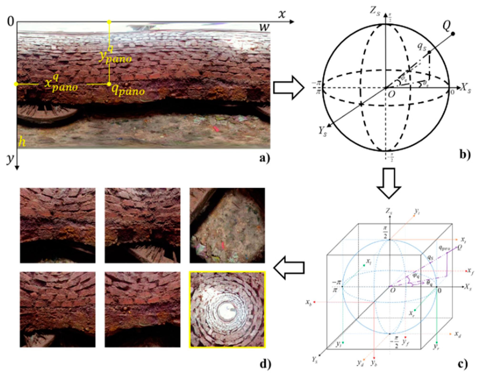
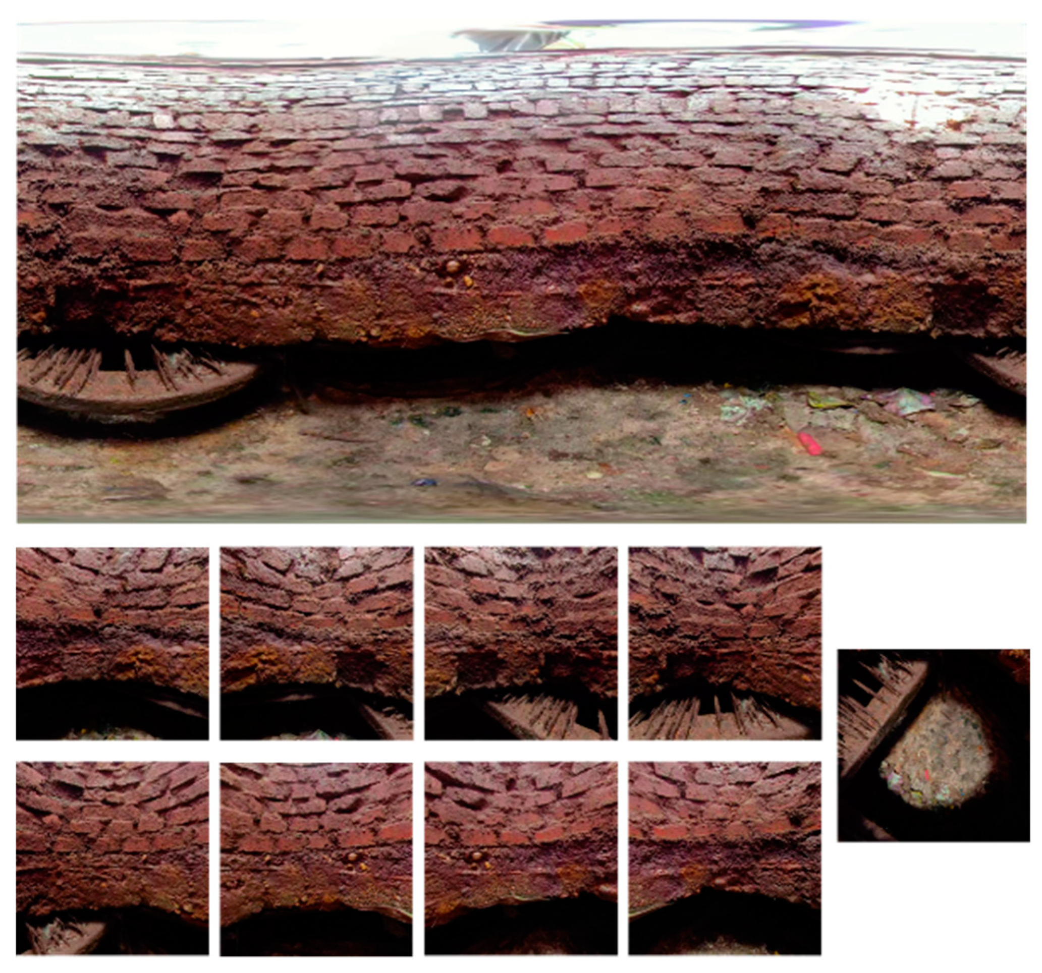
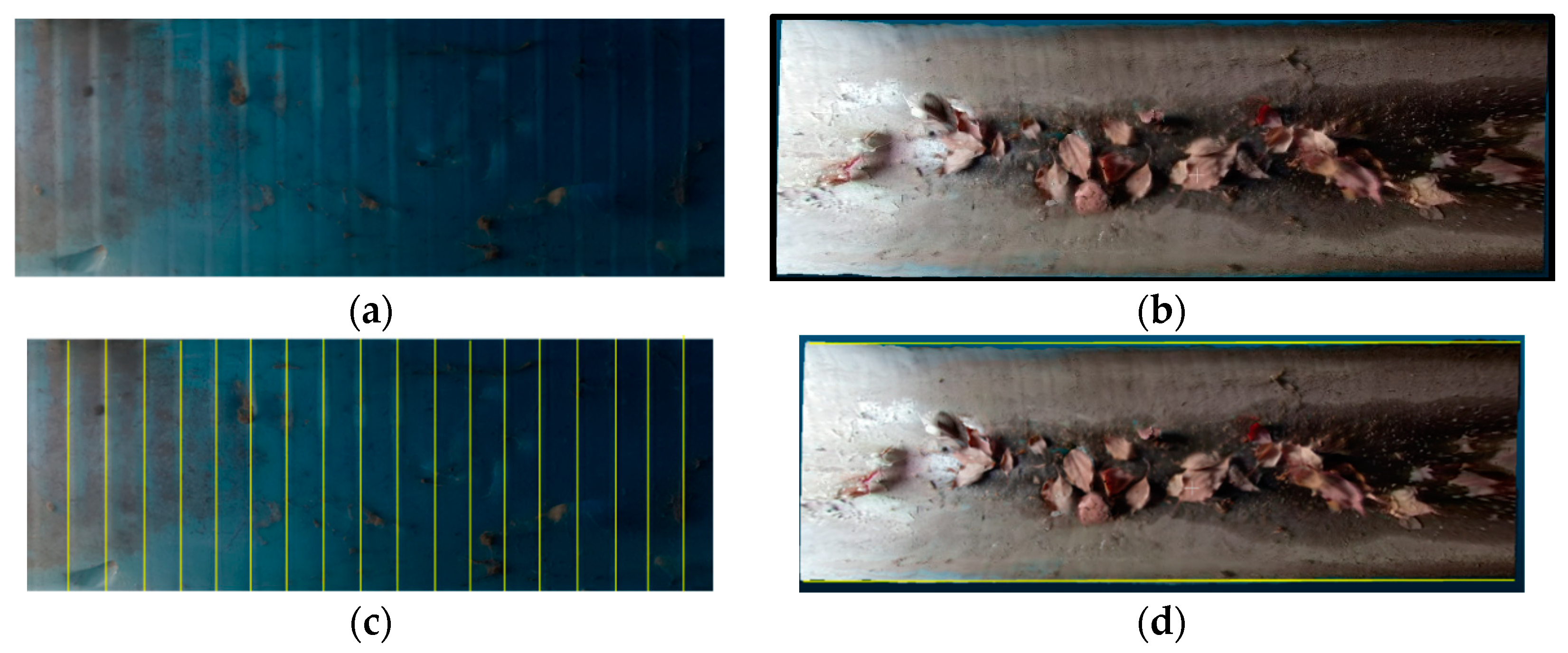
2.2. 2D Panorama Reprojection
2.3. 3D Reconstruction
3. Experiments and Results
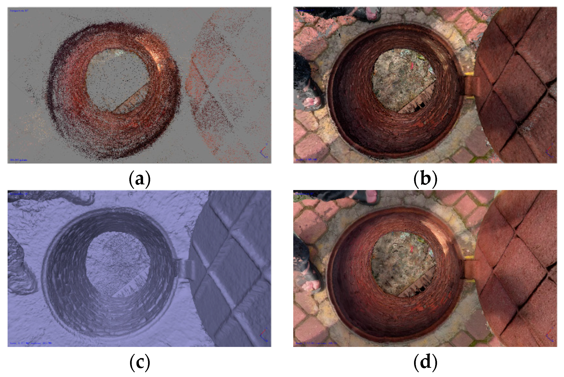
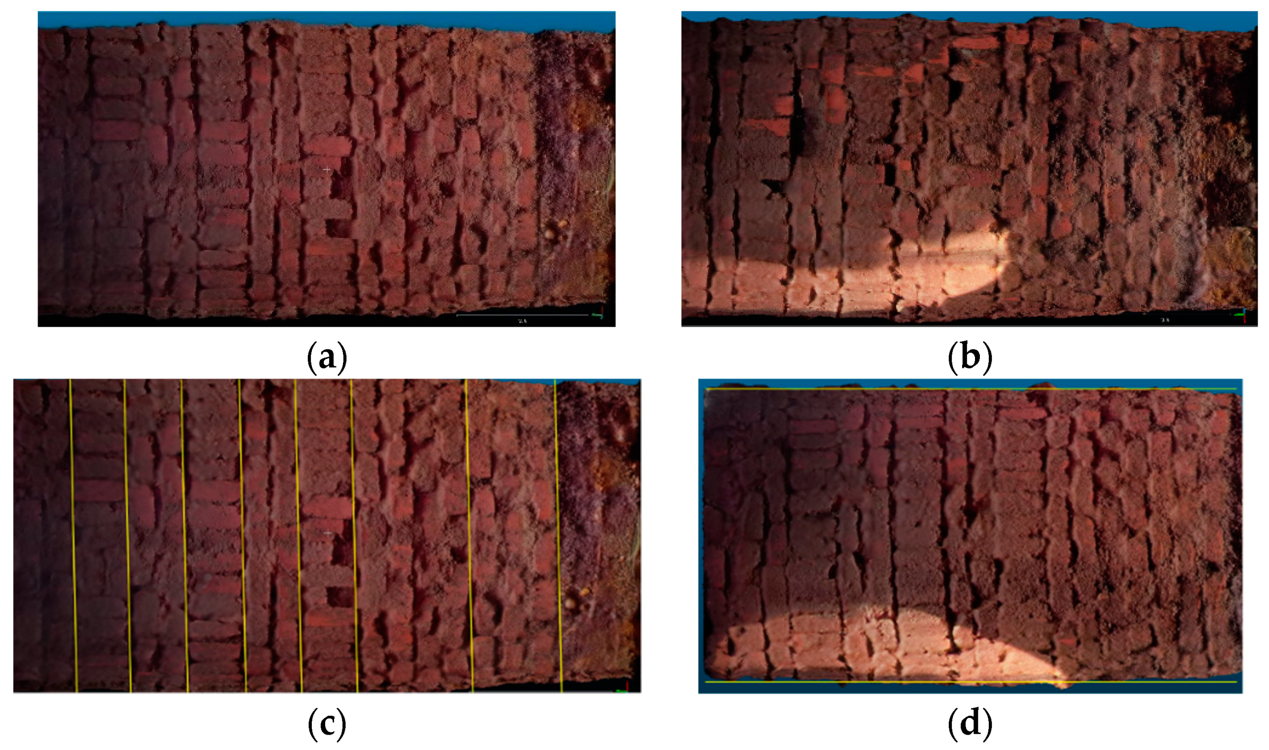
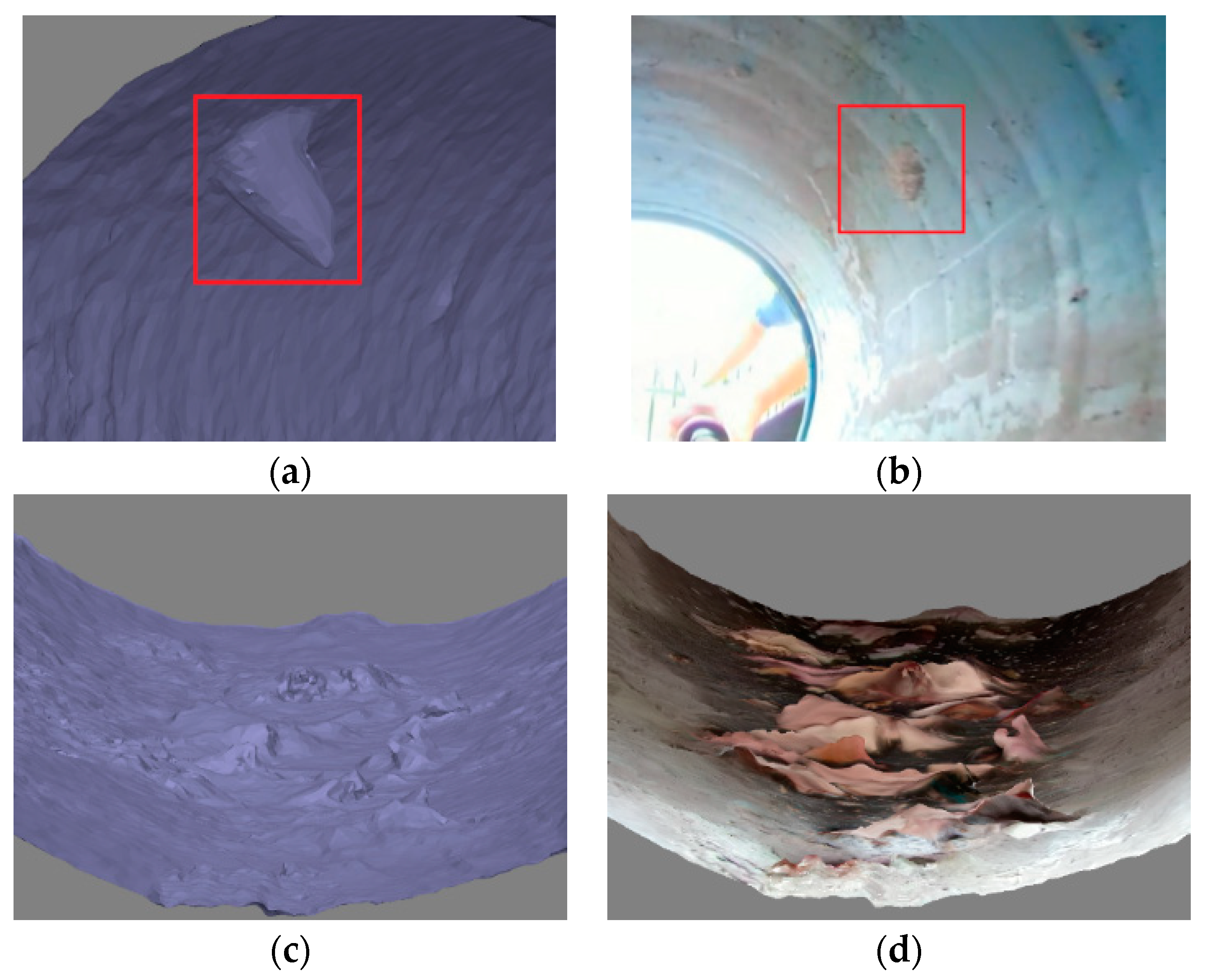
3.1. Scene 1
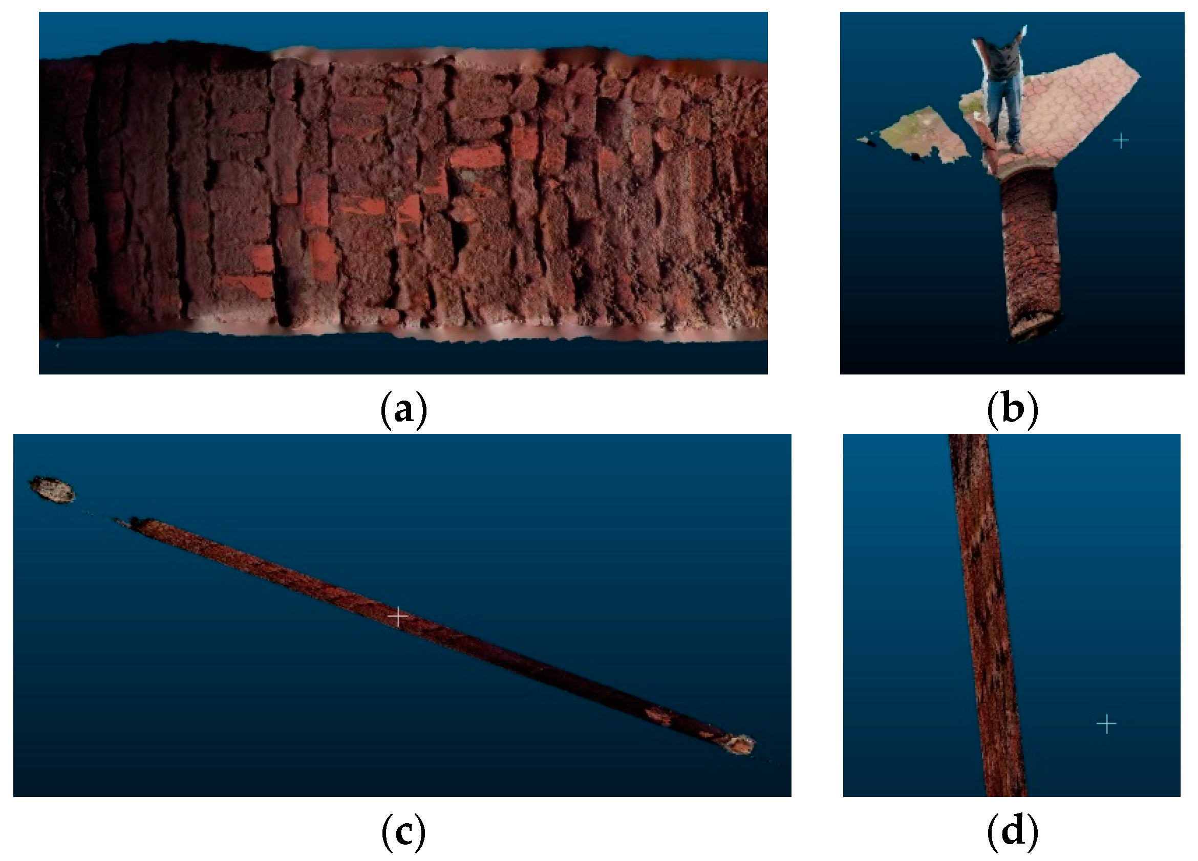
3.2. Scene 2
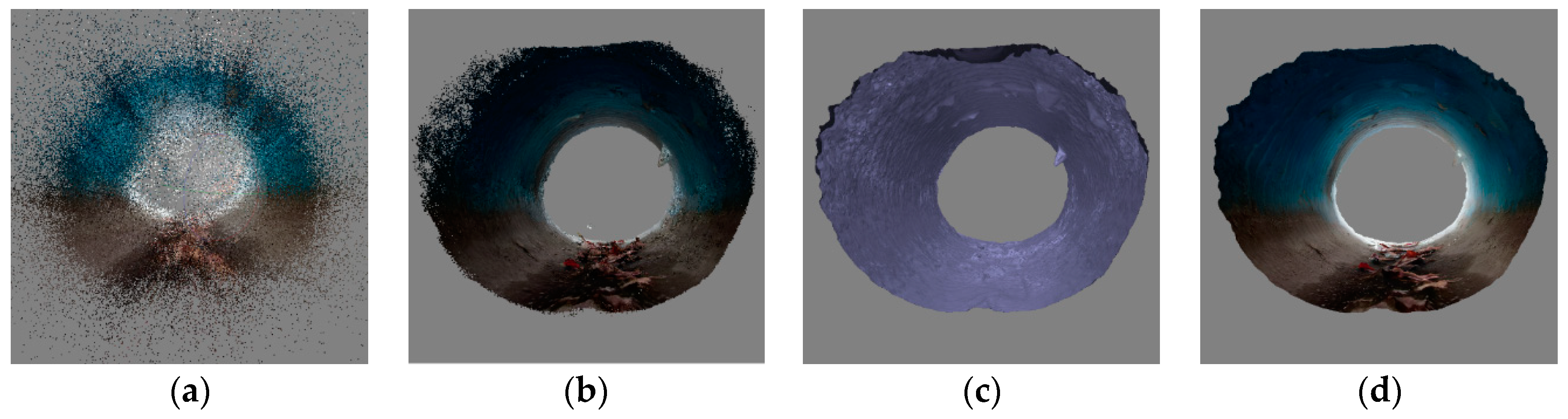
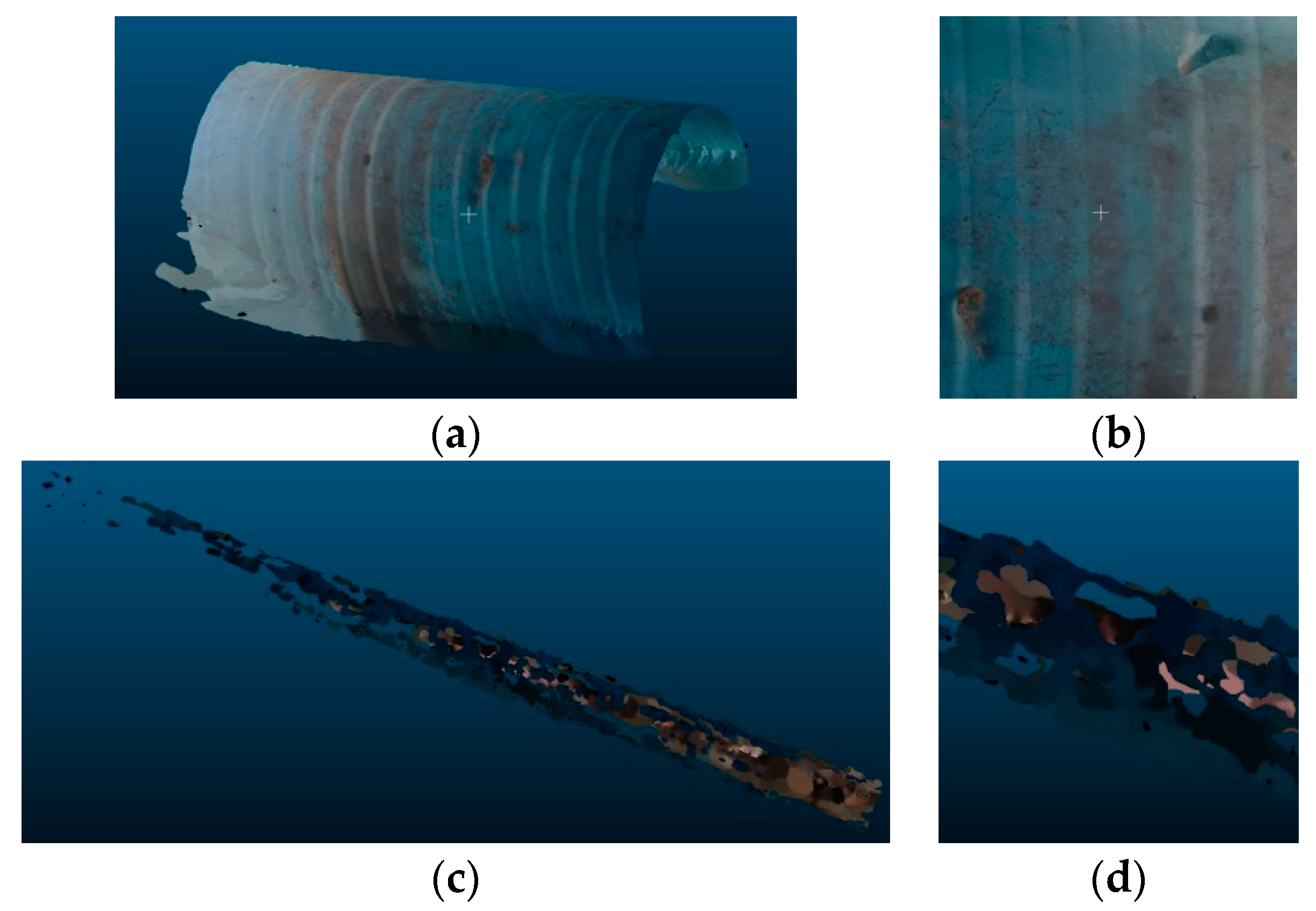
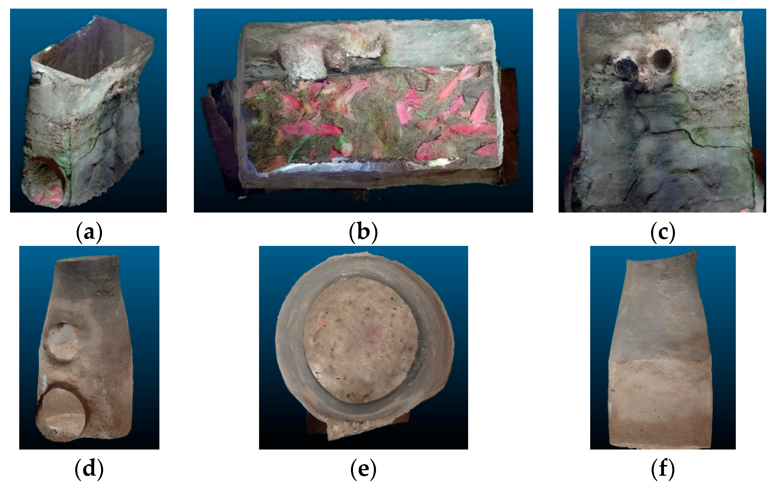
3.3. Other Scenes
4. Discussion
5. Conclusions
Author Contributions
Funding
Acknowledgments
Conflicts of Interest
References
- Jung, D.; Kim, J.H. Robust Meter Network for Water Distribution Pipe Burst Detection. Water 2017, 9, 820. [Google Scholar] [CrossRef]
- Cheng, W.; Xu, G.; Fang, H.; Zhao, D. Study on Pipe Burst Detection Frame Based on Water Distribution Model and Monitoring System. Water 2019, 11, 1363. [Google Scholar] [CrossRef]
- Liu, Z.; Krys, D. The use of laser range finder on a robotic platform for pipe inspection. Mech. Syst. Signal Process. 2012, 31, 246–257. [Google Scholar] [CrossRef]
- Matos, J.S. Comparison of the inspector and rating protocol uncertainty influence in the condition rating of sewers. Water Sci. Technol. 2014, 69, 862–867. [Google Scholar]
- Lepot, M.; Stanić, N.; Clemens, F. A technology for sewer pipe inspection (Part 2): Experimental assessment of a new laser profiler for sewer defect detection and quantification. Autom. Constr. 2017, 73, 1–11. [Google Scholar] [CrossRef]
- Son, H.; Kim, C.; Kim, C. 3D reconstruction of as-built industrial instrumentation models from laser-scan data and a 3D CAD database based on prior knowledge. Autom. Constr. 2015, 49, 193–200. [Google Scholar] [CrossRef]
- Dirksen, J.; Clemens, F.; Korving, H.; Cherqui, F.; Le Gauffre, P.; Ertl, T.; Plihal, H.; Müller, K.; Snaterse, C.T.M. The consistency of visual sewer inspection data. Struct. Infrastruct. Eng. 2013, 9, 214–228. [Google Scholar] [CrossRef]
- Su, T.-C.; Yang, M.-D.; Wu, T.-C.; Lin, J.-Y. Morphological segmentation based on edge detection for sewer pipe defects on CCTV images. Expert Syst. Appl. 2011, 38, 13094–13114. [Google Scholar] [CrossRef]
- Carballini, J.; Viana, F. Using synthetic aperture sonar as an effective tool for pipeline inspection survey projects. In Proceedings of the2005 IEEE/OES Acoustics in Underwater Geosciences Symposium (RIO Acoustics), Rio de Janeiro, Brazil, 29–31 July 2015; pp. 1–5. [Google Scholar]
- Teixeira, P.V.; Kaess, M.; Hover, F.S.; Leonard, J.J. Underwater inspection using sonar-based volumetric submaps. In Proceedings of the 2016 IEEE/RSJ International Conference on Intelligent Robots and Systems (IROS), Daejeon, Korea, 9–14 October 2016; pp. 4288–4295. [Google Scholar]
- Iyer, S.; Sinha, S.K.; Tittmann, B.R.; Pedrick, M.K. Ultrasonic signal processing methods for detection of defects in concrete pipes. Autom. Constr. 2012, 22, 135–148. [Google Scholar] [CrossRef]
- Hoshina, M.; Toyama, S. Development of Spherical Ultrasonic Motor as a Camera Actuator for Pipe Inspection Robot. J. Vibroengineering 2009, 13, 2379–2384. [Google Scholar]
- Huang, H.; Yan, J.; Cheng, T. Development and Fuzzy Control of a Pipe Inspection Robot. IEEE Trans. Ind. Electron. 2010, 57, 1088–1095. [Google Scholar] [CrossRef]
- Nassiraei, A.A.F.; Kawamura, Y.; Ahrary, A.; Mikuriya, Y.; Ishii, K. Concept and design of a fully autonomous sewer pipe inspection mobile robot “KANTARO”. In Proceedings of the IEEE International Conference on Robotics and Automation, Roma, Italy, 10–14 April 2007; pp. 136–143. [Google Scholar]
- Stylianou, G.; Lanitis, A. Image Based 3D Face Reconstruction: A Survey. Int. J. Image Graph. 2009, 9, 217–250. [Google Scholar] [CrossRef]
- De Reu, J.; De Smedt, P.; Herremans, D.; Van Meirvenne, M.; Laloo, P.; De Clercq, W. On introducing an image-based 3D reconstruction method in archaeological excavation practice. J. Archaeol. Sci. 2014, 41, 251–262. [Google Scholar] [CrossRef]
- Gonzalez-Aguilera, D.; López Fernández, L.; Rodríguez-Gonzálvez, P.; Hernandez, D.; Guerrero, D.; Remondino, F.; Menna, F.; Nocerino, E.; Toschi, I.; Ballabeni, A.; et al. GRAPHOS—Open-source software for photogrammetric applications. Photogramm. Rec. 2018, 33, 11–29. [Google Scholar] [CrossRef]
- Knyaz, V. Image-based 3d reconstruction and analysis for orthodontia. ISPRS Int. Arch. Photogramm. Remote Sens. Spat. Inf. Sci. 2012, XXXIX-B3, 585–589. [Google Scholar] [CrossRef]
- Wolff, K.; Kim, C.; Zimmer, H.; Schroers, C.; Botsch, M.; Sorkine-Hornung, O.; Sorkine-Hornung, A. Point Cloud Noise and Outlier Removal for Image-Based 3D Reconstruction. In Proceedings of the 2016 Fourth International Conference on 3D Vision (3DV), Stanford, CA, USA, 25–28 October 2016; pp. 118–127. [Google Scholar]
- Yang, M.-D.; Chao, C.-F.; Huang, K.-S.; Lu, L.-Y.; Chen, Y.-P. Image-Based 3D Scene Reconstruction and Exploration in Augmented Reality. Autom. Constr. 2013, 33, 48–60. [Google Scholar] [CrossRef]
- Liénard, J.; Vogs, A.; Gatziolis, D.; Strigul, N. Embedded, real-time UAV control for improved, image-based 3D scene reconstruction. Measurement 2016, 81, 264–269. [Google Scholar] [CrossRef]
- Wu, C. Towards linear-time incremental structure from motion. In Proceedings of the 2013 International Conference on 3D Vision, Seattle, WA, USA, 29 June–1 July 2013; pp. 127–134. [Google Scholar]
- Özyesil, O.; Voroninski, V.; Basri, R.; Singer, A. A survey of structure from motion. Acta Numer. 2017, 26, 305–364. [Google Scholar] [CrossRef]
- Lowe, D.G. Distinctive image features from scale-invariant keypoints. Int. J. Comput. Vis. 2004, 60, 91–110. [Google Scholar] [CrossRef]
- Frahm, J.-M.; Fite-Georgel, P.; Gallup, D.; Johnson, T.; Raguram, R.; Wu, C.; Jen, Y.-H.; Dunn, E.; Clipp, B.; Lazebnik, S.; et al. Building Rome on a cloudless day. In Computer Vision—ECCV; Springer: Berlin/Heidelberg, Germany, 2010; pp. 368–381. [Google Scholar]
- Agarwal, S.; Snavely, N.; Seitz, S.M.; Szeliski, R. Bundle adjustment in the large. In Computer Vision—ECCV; Springer: Berlin/Heidelberg, Germany, 2010; pp. 29–42. [Google Scholar]
- Byröd, M.; Åström, K. Conjugate gradient bundle adjustment. In Computer Vision—ECCV; Springer: Berlin/Heidelberg, Germany, 2010; pp. 114–127. [Google Scholar]
- Furukawa, Y.; Ponce, J. Accurate, dense, and robust multiview stereopsis. IEEE Trans. Pattern Anal. Mach. Intell. 2010, 32, 1362–1376. [Google Scholar] [CrossRef]
- Geiger, A.; Ziegler, J.; Stiller, C. StereoScan: Dense 3d reconstruction in real-time. In Proceedings of the IEEE Intelligent Vehicles Symposium, Baden-Baden, Germany, 5–9 June2011; pp. 963–968. [Google Scholar]
- Seitz, S.M.; Curless, B.; Diebel, J.; Scharstein, D.; Szeliski, R. A comparison and evaluation of multi-view stereo reconstruction algorithms. In Proceedings of the 2006 IEEE Computer Society Conference on Computer Vision and Pattern Recognition, New York, NY, USA, 17–22 June 2006; Volume 1, pp. 519–528. [Google Scholar]
- Wenzel, K.; Rothermel, M.; Fritsch, D.; Haala, N. Image acquisition and model selection for multi-view stereo. ISPRS Int. Arch. Photogramm. Remote Sens. Spat. Inf. Sci. 2013, XL-5/W1, 251–258. [Google Scholar] [CrossRef]
- Su, T.; Wang, W.; Lv, Z.; Wu, W.; Li, X. Rapid Delaunay triangulation for randomly distributed point cloud data using adaptive Hilbert curve. Comput. Graph. 2016, 54, 65–74. [Google Scholar] [CrossRef]
- Zeng, W.; Liu, G.R. Smoothed finite element methods (S-FEM): An overview and recent developments. Arch. Comput. Methods Eng. 2018, 25, 397–435. [Google Scholar] [CrossRef]
- Chen, Z.; Zhou, J.; Chen, Y.; Wang, G. 3D Texture mapping in multi-view reconstruction. In Advances in Visual Computing; Springer: Berlin/Heidelberg, Germany, 2012; pp. 359–371. [Google Scholar]
- Jeon, J.; Jung, Y.; Kim, H.; Lee, S. Texture map generation for 3D reconstructed scenes. Vis. Comput. 2016, 32, 955–965. [Google Scholar] [CrossRef]
- Berger, M.; Tagliasacchi, A.; Seversky, L.M.; Alliez, P.; Guennebaud, G.; Levine, J.A.; Sharf, A.; Silva, C.T. A survey of surface reconstruction from point clouds. Comput. Graph. Forum 2017, 36, 301–329. [Google Scholar] [CrossRef]
- Campos, R.; Garcia, R.; Alliez, P.; Yvinec, M. A surface reconstruction method for in-detail underwater 3d optical mapping. Int. J. Rob. Res. 2015, 34, 64–89. [Google Scholar] [CrossRef]
- Bruno, F.; Bruno, S.; De Sensi, G.; Luchi, M.-L.; Mancuso, S.; Muzzupappa, M. From 3D reconstruction to virtual reality: A complete methodology for digital archaeological exhibition. J. Cult. Herit. 2010, 11, 42–49. [Google Scholar] [CrossRef]
- Macher, H.; Grussenmeyer, P.; Landes, T.; Halin, G.; Chevrier, C.; Huyghe, O. Photogrammetric recording and reconstruction of town scale models—The case of the plan-relief of Strasbourg. ISPRS Int. Arch. Photogramm. Remote Sens. Spat. Inf. Sci. 2017, XLII-2/W5, 489–495. [Google Scholar] [CrossRef]
- Pietroni, E.; Forlani, M.; Rufa, C. Livia’s Villa Reloaded: An example of re-use and update of a pre-existing Virtual Museum, following a novel approach in storytelling inside virtual reality environments. In Proceedings of the 2015 Digital Heritage, Granada, Spain, 28 September–2 October2015; Volume 2, pp. 511–518. [Google Scholar]
- Santagati, C.; Inzerillo, L.; Di Paola, F. Image-based modeling techniques for architectural heritage 3D digitalization: Limits and potentialities. Int. Arch. Photogramm. Remote Sens. Spat. Inf. Sci. 2013, XL-5, 550–560. [Google Scholar] [CrossRef]
- Kuschk, G. Model-free Dense Stereo Reconstruction Creating Realistic 3D City Models. In Proceedings of the Joint Urban Remote Sensing Event, Sao Paulo, Brazil, 21–23 April 2013; pp. 202–205. [Google Scholar]
- Qu, Y.; Huang, J.; Zhang, X. Rapid 3D Reconstruction for Image Sequence Acquired from UAV Camera. Sensors 2018, 18, 225. [Google Scholar]
- Wu, B.; Xie, L.; Hu, H.; Zhu, Q.; Yau, E. Integration of aerial oblique imagery and terrestrial imagery for optimized 3D modeling in urban areas. ISPRS J. Photogramm. Remote Sens. 2018, 139, 119–132. [Google Scholar] [CrossRef]
- Singh, S.P.; Jain, K.; Mandla, V.R. Image based 3D city modeling: Comparative study. ISPRS Int. Arch. Photogramm. Remote Sens. Spat. Inf. Sci. 2014, XL-5, 537–546. [Google Scholar] [CrossRef]
- Reyes-Acosta, A.; Lopez-Juarez, I.; Osorio-Comparan, R.; Lefranc, G. Towards 3D pipe reconstruction employing affine transformations from video information. In Proceedings of the 2016 IEEE International Conference on Automatica (ICA-ACCA), Curico, Chile, 19–21 October 2016; pp. 1–6. [Google Scholar]
- Zhang, T.; Liu, J.; Liu, S.; Tang, C.; Jin, P. A 3D reconstruction method for pipeline inspection based on multi-vision. Measurement 2017, 98, 35–48. [Google Scholar] [CrossRef]
- Eichhardt, I.; Chetverikov, D.; Jankó, Z. Image-guided ToF depth upsampling: A survey. Mach. Vis. Appl. 2017, 28, 267–282. [Google Scholar] [CrossRef]
- Rubinsztein-Dunlop, H.; Forbes, A.; Berry, M.V.; Dennis, M.R.; Andrews, D.L.; Mansuripur, M.; Denz, C.; Alpmann, C.; Banzer, P.; Bauer, T.; et al. Roadmap on structured light. J. Opt. 2017, 19, 13001. [Google Scholar] [CrossRef]
- Sun, Y.; Liu, M.; Meng, M.Q.-H. Improving RGB-D slam in dynamic environments: A motion removal approach. Rob. Auton. Syst. 2017, 89, 110–122. [Google Scholar] [CrossRef]
- Brown, M.; Lowe, D.G. Automatic Panoramic Image Stitching using Invariant Features. Int. J. Comput. Vis. 2007, 74, 59–73. [Google Scholar] [CrossRef]
- Lee, W.-T.; Chen, H.-I.; Chen, M.-S.; Shen, I.-C.; Chen, B.-Y. High-resolution 360 Video Foveated Stitching for Real-time VR. Comput. Graph. Forum 2017, 36, 115–123. [Google Scholar] [CrossRef]
- Li, L.; Yao, J.; Xie, R.; Xia, M.; Zhang, W. A Unified Framework for Street-View Panorama Stitching. Sensors 2017, 17, 1. [Google Scholar] [CrossRef]
- Shum, H.-Y.; Szeliski, R. Systems and Experiment Paper: Construction of Panoramic Image Mosaics with Global and Local Alignment. Int. J. Comput. Vis. 2000, 36, 101–130. [Google Scholar] [CrossRef]
- Paris, L.; Calvano, M.; Nardinocchi, C. Web Spherical Panorama for Cultural Heritage 3D Modeling. In New Activities for Cultural Heritage; Springer: Cham, Switzerland, 2017; pp. 182–189. [Google Scholar]
- Wahbeh, W.; Nebiker, S.; Fangi, G. Combining public domain and professional panoramic imagery for the accurate and dense 3d reconstruction of the destroyed bel temple in Palmyra. ISPRS Ann. Photogramm. Remote Sens. Spat. Inf. Sci. 2016, III-5, 81–88. [Google Scholar] [CrossRef]
- Yang, H.; Zhang, H. Efficient 3D Room Shape Recovery from a Single Panorama. In Proceedings of the 2016 IEEE Conference on Computer Vision and Pattern Recognition (CVPR), Las Vegas, NV, USA, 27–30 June 2016; pp. 5422–5430. [Google Scholar]
- Li, J.; Hu, Q.; Ai, M.; Zhong, R. Robust feature matching via support-line voting and affine-invariant ratios. ISPRS J. Photogramm. Remote Sens. 2017, 132, 61–76. [Google Scholar] [CrossRef]


| Direction | ||||
|---|---|---|---|---|
| (3) | (9) | |||
| (4) | (10) | |||
| (5) | (11) | |||
| (6) | ||||
| (7) | ||||
| (8) |
| Scene | Size | Material | Texture Richness |
|---|---|---|---|
| Scene 1 | large | brick | good |
| Scene 2 | narrow | plastic | uneven |
| Scene 3 | secondary | cement | secondary |
| Scene 4 | small | cement | poor |
© 2019 by the authors. Licensee MDPI, Basel, Switzerland. This article is an open access article distributed under the terms and conditions of the Creative Commons Attribution (CC BY) license (http://creativecommons.org/licenses/by/4.0/).
Share and Cite
Zhang, X.; Zhao, P.; Hu, Q.; Wang, H.; Ai, M.; Li, J. A 3D Reconstruction Pipeline of Urban Drainage Pipes Based on MultiviewImage Matching Using Low-Cost Panoramic Video Cameras. Water 2019, 11, 2101. https://doi.org/10.3390/w11102101
Zhang X, Zhao P, Hu Q, Wang H, Ai M, Li J. A 3D Reconstruction Pipeline of Urban Drainage Pipes Based on MultiviewImage Matching Using Low-Cost Panoramic Video Cameras. Water. 2019; 11(10):2101. https://doi.org/10.3390/w11102101
Chicago/Turabian StyleZhang, Xujie, Pengcheng Zhao, Qingwu Hu, Hean Wang, Mingyao Ai, and Jiayuan Li. 2019. "A 3D Reconstruction Pipeline of Urban Drainage Pipes Based on MultiviewImage Matching Using Low-Cost Panoramic Video Cameras" Water 11, no. 10: 2101. https://doi.org/10.3390/w11102101
APA StyleZhang, X., Zhao, P., Hu, Q., Wang, H., Ai, M., & Li, J. (2019). A 3D Reconstruction Pipeline of Urban Drainage Pipes Based on MultiviewImage Matching Using Low-Cost Panoramic Video Cameras. Water, 11(10), 2101. https://doi.org/10.3390/w11102101