Article

Long-Term Shoreline Displacements and Coastal Morphodynamic Pattern of North Rhodes Island, Greece

by
Fragkiska-Karmela Gad
1,
Giorgos-Angelos Hatiris
1,2,*,
Vassiliki Loukaidi
1,
Stavroula Dimitriadou
2,
Paraskevi Drakopoulou
1,2,
Andreas Sioulas
1 and
Vasilios Kapsimalis
1
1
Hellenic Centre for Marine Research (HCMR), Institute of Oceanography, 46.7 km Athens-Sounio Ave., P.O. Box 712, P.C.19013 Anavissos, Greece
2
Geography Department, Harokopio University, El. Venizelou 70, 17671 Athens, Greece
*
Author to whom correspondence should be addressed.
Water 2018, 10(7), 849; https://doi.org/10.3390/w10070849
Submission received: 31 March 2018 / Revised: 11 June 2018 / Accepted: 19 June 2018 / Published: 26 June 2018

Abstract

:
Shoreline evolution and seabed morphology changes depend on coastal geomorphology as well as hydrodynamics of the nearshore region. Τhis study investigates the morphological evolution of the northernmost headland of Rhodes Island, Greece, using a method that combines historical shoreline evolution analysis and numerical modelling of coastal processes. The satellite and aerial imagery analysis under a GIS platform reveals that, since 1982, the overall surface area of the backshore has slightly increased, though in shorter period times, large variations have been identified. The part of the beach that is most prone to extreme changes is the spit-like formation at the tip of the headland. Wind-generated waves and induced currents are the main forcing factors that affect the shape and orientation of the spit-like beach. This spit-like morphology changes seasonally due to variations in the dominant wave regime. West sector waves cause sediment deposition at the eastern sector of the spit-like formation, whereas strong southeast wave events during the winter favor accretion at the west sector, inducing an asymmetrical shape. Thus, the analysis results indicate an annual balance in sediment transport.

1. Introduction

Coastal areas are highly dynamic and changeable systems affected by a number of natural and anthropogenic forcing factors, such as wind and waves directional change [1,2], currents [3,4], sea-level fluctuations [5,6], sediment budget [7,8], topography [9,10], tectonics [11,12], presence of coastal infrastructures, and sand extraction [13,14]. The results of the above processes can cause variations of shore morphology in long and short time spans, and therefore it can impact the coastal environmental quality, socioeconomic value, security of beaches and harbours, and natural resources [15].
In particular, the presence of curved planforms, as headlands, alters the regional morphodynamic pattern causing significant displacements of the shoreline and seabed level [16]. Such landforms are usually exposed to high wave energy and nearshore currents, which are the basic components that influence sediment transport and contribute to sand bypassing processes around the tip of headland. Thus, a shoal may be formed by the accretion of non-cohesive sediments on the leeward side of the headland [17,18,19]. The orientation of this spit-like beach usually indicates the direction of dominant littoral drift [20,21], though inlet channel geometry, wave refraction, and tidal flow can overturn the above perception [22]. The short-term (order of days to a year) changes of a headland should be carefully considered since they cause temporary alternations [23] and often return to their initial situation over time [24] following a period of relaxation [25]. Changes in a spit's orientation and shape result as a consequence of varying wave climate. Waves propagating toward a shore from varying directions contribute to littoral transport affecting shoreline evolution and spit growth. Long-term (order of a year to decades) variations are usually estimated by comparing aerial photographs or satellite images, historic maps and data derived by topographic survey techniques [26].
During the last two decades, remote sensing and geographical information system (GIS) platforms have been extensively used in coastal geomorphological investigations. Through these techniques researches can depict shore configuration and landforms, detect shoreline positions and historic changes, and reveal the sediment transport pathways and erosion/accretion rates. In addition, numerical modeling is often used for describing and predicting physical processes in the nearshore zone, over selected space and time scales [27]. Today, several 2D and 3D numerical models are available for the simulation of coastal hydro- and morpho- dynamics, such as wave propagation, littoral circulation currents, sediment drift, and shoreline evolution. Τhere are also advanced models that simulate the interaction among waves currents and changes in bathymetry by using a dynamic coupling [28,29]. Numerical models are also applied for impact assessment of engineering structures, such as coastal protection projects or harbor works in a specific site.
The present paper (a) records historical shoreline positions of the spit-like beach located in a wave-dominated micro-tidal system, in the northernmost headland of Rhodes Island (Greece) using multi-temporal aerial photographs and satellite images, (b) estimates the geometric changes of subaerial part of shore by means of geospatial analysis and statistical techniques, and (c) simulates the local morphodynamic pattern applying a hydrodynamic and sediment transport model. The data derived from the above multi-proxy approach are used to achieve the main purpose of this article that is to reveal the littoral processes responsible for the long-term beach evolution, which, despite of its small size, is of high interest since it is a mass touristic destination and a landmark of Rhodes Island. In addition, this study fills the gap of morphodynamics around a wave-dominated micro-tidal headland beach, since the majority of previous research focuses on curved planforms in tide-dominated environments [17,18,20,30].

2. The Study Area

Rhodes Island is located in the southeastern Aegean Sea, Greece. It is the fourth-largest Greek island, with an area of 1400 km2 and a total coastline length of 253 km. Its permanent population is 115,490 inhabitants, according to the 2011 census. The case study area is a touristic beach situated at the northern tip of the island (Figure 1). It has a bell-curve shape extending on both sides of the Cape Mylon. It is about 1.3 km long and there are no coastal structures along the shore. Its western part is directed NE-SW facing NW, while its eastern part is directed SE-NW facing NE.
The beach topography and shoreface bathymetry were provided by [31,32], respectively. The mean slope of the subaerial beach is about 7% in both sides of the headland, and approximately 3% in the northern tip. The shoreface slope, it is relatively steep in the west side (11% at depths from msl to 5 m, and 35% in the deeper zone), lower in the northern tip (9% at depths from msl to 5 m to 9 m, and >20% in the deeper zone) and even lower in the eastern part (7% at depths from msl to 8 m, 2% from 8 m to 11 m, and 10% in the deeper zone).
The beach sediment consists of coarse grained material (sized from sand to cobble with grain diameter up to 6 cm) (Figure 2), while in very shallow waters, sand and cobble deposits (grain size up to 2 cm) (Figure 2b) as well as rock outcrops (Figure 2c) occur (Figure 2b,c) [31,33,34]. At depths from 10 m to 30 m, meadows of Posidonia ocenica dominate, while the deeper parts of the seabed (at depths more than 30 m) is covered by relatively fine-grained sediments (very fine sand, silt, and clay), though in some places there are patches of coarse sand and gravel transported from the adjacent land through occasional gravity flow processes.
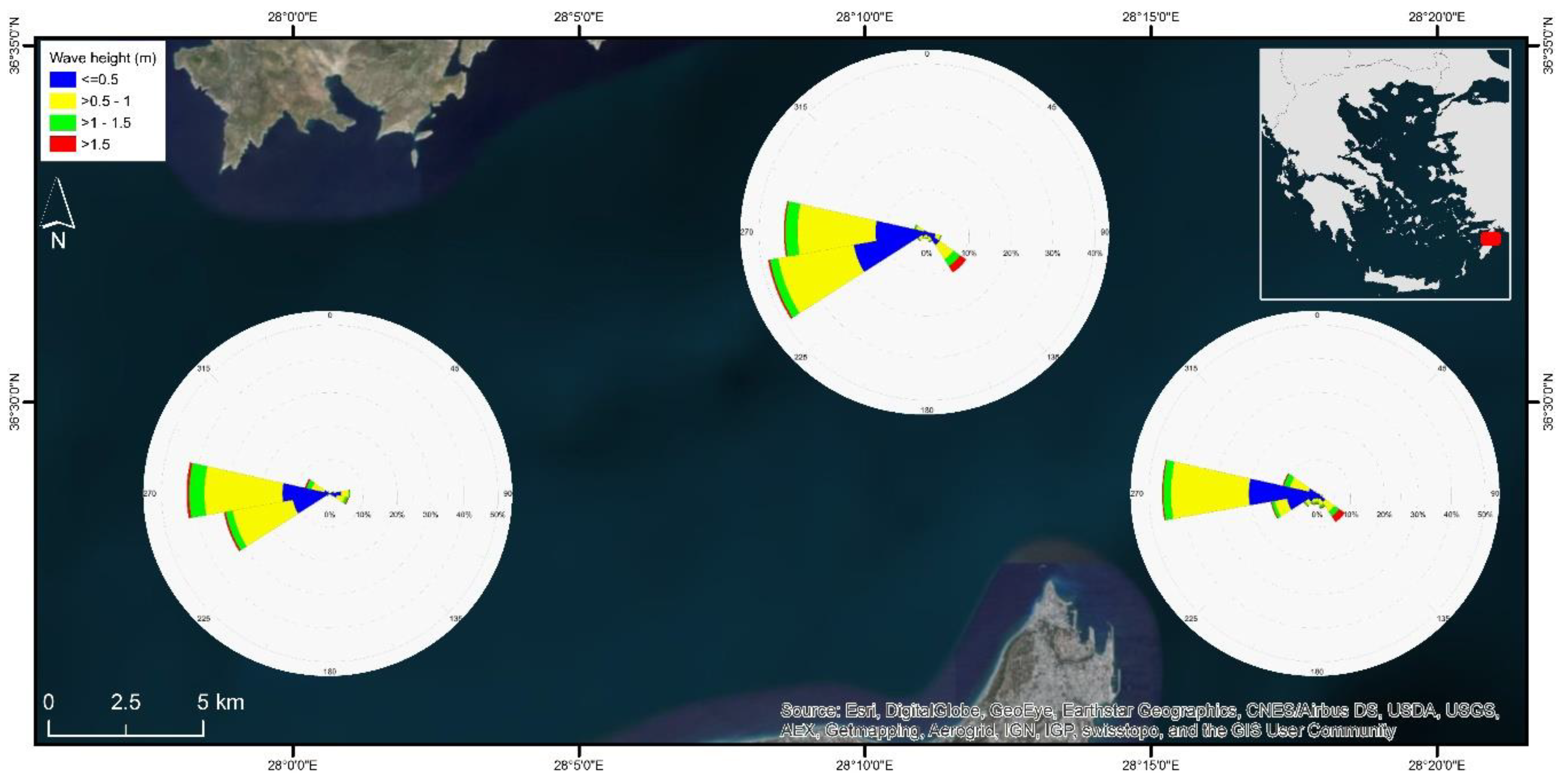
Concerning the wind and wave climate in the wider region, the analysis has been based on data derived from the “Wind and Wave Atlas of the Hellenic Sea” [35]. A 10-year hindcast dataset (1995–2004) reveals that the prevailing wind directions are west (W), southwest (SW) and northwest (NW). However, the strongest winds blow from the southeast (SE), with speed values up to 18 m/s during the winter. The dominant wave directions propagate from the west (W) and west-southwest (W-SW) sector, while the most extreme events come from the southeast (SE), occurring mostly throughout the winter months. During strong SE winds with great fetches, significant wave height reaches a value up to 4.5 m with an average peak period of about 8.5 s. Normal peak period values range from 3 to 4.5 s highlighting that wind-generated waves are the most common in the study area, with the exception of a very small percentage of events (about 0.01%) that are swell (Tp > 15 s) (Figure 3). The tidal range in the port of Rhodes varies between a 0.1 m (min) and 0.36 m (max), while the mean range is 0.14 m during the time period 2010–2012 [36]. According to Pytharouli and Stiros [37], the astronomical component of tide in the region is of the order of 10 cm.

3. Materials and Methods

3.1. Analysis of Shoreline Evolution

Long-term shoreline displacement was determined by the use of multi-temporal raster datasets, derived either from aerial or satellite imagery resources. Two aerial photographs taken in 1982 and 1991 at a scale equal to 1:8.000 were selected by the database of Hellenic Military Geographical Service. Additionally, satellite imagery of a finer resolution covering a 14-year timeline, from 2002 to 2016, was obtained by the Google Earth Pro platform. Google Earth Pro provides satellite imageries taken at different time periods having spatial resolution less than 1 m [38]. The use of these images is an alternative solution for the extraction of the coastline [2,39], since the freely available optical satellite imageries (Landsat, Sentinel 2 etc.) have a spatial resolution no finer than 10 m, and the higher resolution commercial satellite data are costly to acquire. The only limitation of these Google Earth images is that there is not access to the original multispectral data and therefore the supervised or unsupervised image classification cannot be realized. Since the spatial resolution of original data is high (below 1 m) (Table 1), it is possible to visually delineate on-screen the shoreline [40]. Furthermore, the study area is narrow, thus corresponding to a single satellite image frame each time and not a mosaic, which preserves the original image properties.
All images were rectified in a GIS environment (ESRI ArcGIS geospatial platform). For the purpose of rectification, colorful orthophotomaps in resolution of 0.5 m, provided by the National Cadastre and Mapping Agency, were used as the basemap. All raster datasets were rectified in the same coordinate reference system, which is the Greek Grid (EPSG: 2100). During each rectification process, well distributed inside the broader study area Ground Control Points were carefully identified and inserted in order to link each image to its corresponding basemap position. Τhe completion of each rectification process was carried out by the application of a spline transformation model, which is efficient at correcting local distortions by increasing the density of Control Points in the area of interest (i.e., the beach) [41]. In addition, this method ensures the exact placement of control points, preventing deformations having a warping effect on the rest of the image. Thus, the Total Root Mean Square Error (RMSE) for the rectification process was considered null [42].
In order to estimate the uncertainty in shoreline position, three additional sources of errors were estimated, namely digitizing, pixel and tidal errors [43,44]. The digitizing error (Ed) was calculated as the standard deviation of differences of the shoreline position between three repeated digitizations [44] and it was estimated within the range of ±0.8 m to ±2.3 m. The pixel error (Ep) was identified as the pixel size of an image [44], ranging from ±0.34 m to ±0.67 m in satellite images and from ±1.6 to 1.8 m in aerial photographs. The tidal error (Et), being the horizontal movement of shoreline position due to vertical fluctuations of tides, was estimated as the ratio of tidal amplitude to beach slope [14]. Thus, the “total shoreline position error (Esp)” expressed as the root sum of the squares of errors [43]
  E sp = ± E d 2   +   E p 2   +   E t 2
was estimated within the range of ±2.9 m to ±4.0 m. An “annualized error (Ea)” of ±0.4 m/year was obtained in the time period 1982–2016, expressed as the ratio of the root sum of the squares of “total shoreline position errors” of each historical shoreline divided by the time span of the analysis [43]
E a = ± i = 1 n E spi 2 time
where Espi is the “total shoreline position error” of the historical shoreline i and n is the number of historical shorelines used in the analysis.
A total of 18 consecutive historical and recent shorelines along the north coast of Rhodes island, representing the position of mean sea level, were delineated/digitized onscreen based on the manual identification and photo-interpretation of the rectified aerial and satellite datasets.
Shoreline displacement analysis was performed with the use of the Digital Shoreline Analysis System (DSAS) [45] ArcGIS extension. The analysis was based on the quantification of shoreline displacement phenomenon along a predefined set of fixed-paced perpendicularly distributed to a given baseline transects. For the purpose of this study, the Net Shoreline Movement (NSM) statistical analysis module was used to calculate the displacement distance and rates between the oldest (1982) and each of its successive shorelines. Additionally, for each delineated shoreline, a corresponding beach area was defined. Finally, as baseline, i.e., the steady landward boundary of the beach, was collected the curb of the coastal road, since no intervention has been done on this road over the last 40 years.

3.2. Simulation of Coastal Processes

For assessing sediment transport and bed morphological changes, a dynamic numerical model, namely the MIKE 21/3 Coupled Model FM by the DHI, was used. More specifically, the model was applied for the estimation of wave and hydrodynamic conditions, as well as sediment transport and bed level changes.
The MIKE 21/3 Coupled Model FM is a 2DH deterministic model that is applied in coastal areas. It is widely used for describing the current situation of a specific site, planning and design of engineering projects and assessing impacts arising from port infrastructures and/or coastal protection works. It consists, amongst others, of a spectral wave (SW), a hydrodynamic (HD), and a sand (non-cohesive sediment) transport (ST) module. Its basic computational components, the SW and HD modules, simulate the interaction between waves and currents by using a dynamic coupling. The sediment transport depends on the wave and hydrodynamic conditions of a coastal region as well as the physical characteristics of the material (such as grain size, porosity, etc.). The total sediment load is defined as the sum of bed (load being in contact with the seabed) and suspended load transport. Moreover, by coupling all the three modules, a feedback of the bed level changes on the wave and current calculations is included [46].
The model is based on a flexible mesh approach, giving user the ability to generate a proper triangular or quadrilateral mesh size depending on required accuracy of the analysis.
In this study, the model has been applied to four wave scenarios (Table 2) representing annual sediment transport pattern for the study area. The main idea is that the sediment flux is proportional to the energy flux according to the CERC formula [47], so a methodology based on wave energy flux [48] has been followed, in order to select the simulated scenarios.
  • Data are grouped into wave classes with associated annual probability of occurrence. Then, the actual energy flux is determined as fiHi2Ti, where Hi is the wave significant height, Ti is the wave period and fi denotes the probability of occurrence of the specific event, i.
  • As representative event is defined the one that maximizes the energy flux and its probability of occurrence is determined as
    fmax = Σ(fi Ηi2 Ti)/(Ηi2 Ti)max
This means that this event causes sediment transport equivalent to the annual budget when occurring with a frequency of fmax.
As the longshore transport may be directed to the right (of an observer looking seaward) or to the left, depending on wave propagation direction, calculations have been applied to two different groups of events, namely the ones that cause littoral drift to the right and the ones to the left.
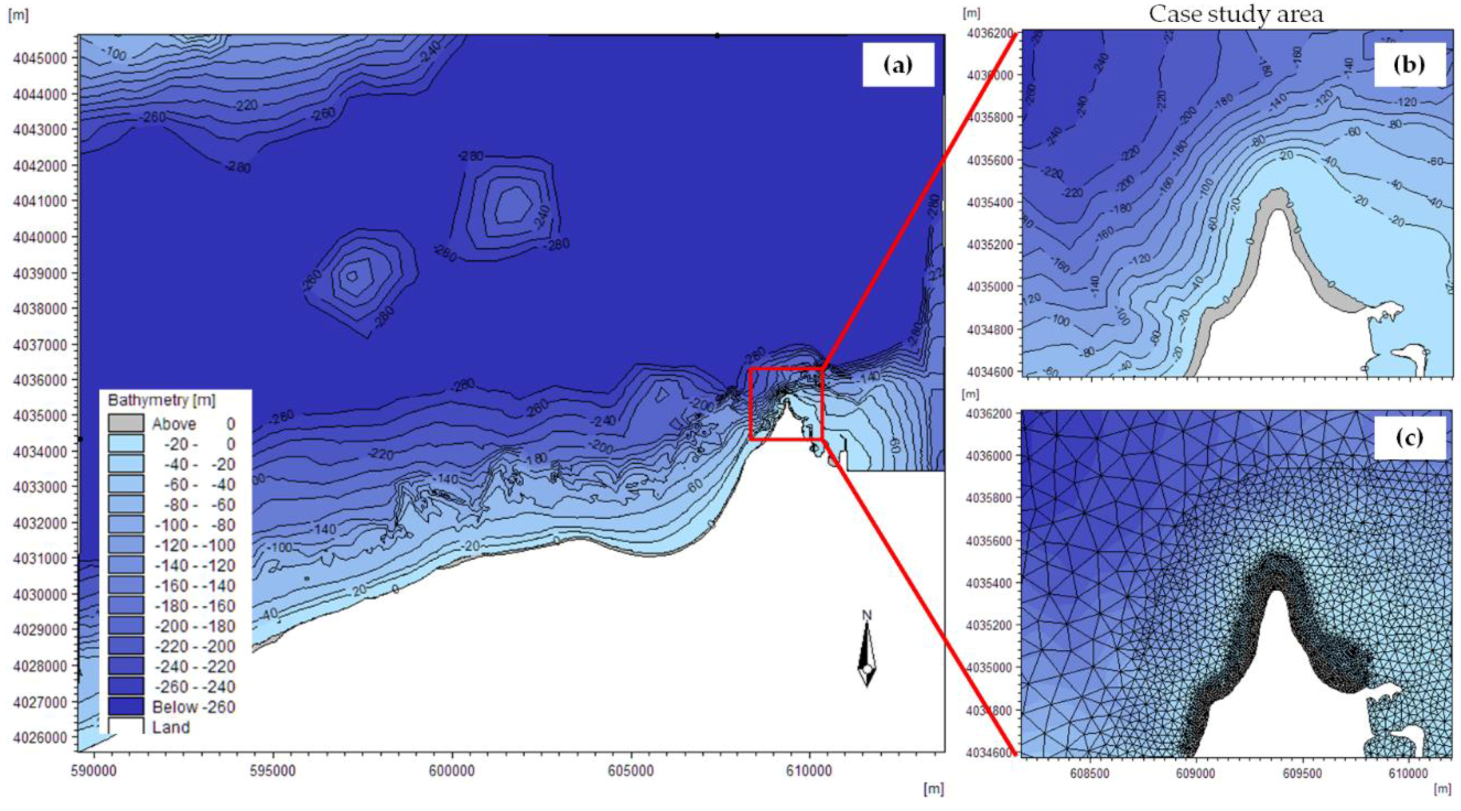
Topographic and bathymetric data were collected by the HCMR database [31,32] and from nautical maps of the Hellenic Navy Hydrographic Service and digital topographic data from the Hellenic Cadastre. The model domain covers an area of 20 km × 15 km. The triangular mesh consists of 27,777 elements; a fine mesh is used in the area of interest (with min and average area of mesh elements approximately 22 m2 and 65 m2, respectively), and a coarser one in the offshore zone. The UTM 35 coordinate system has been specified as reference system in the present study. In Figure 4, the model domain and the study area bathymetry and computational mesh are presented.
Regarding sediment properties, two different classes have been introduced to the model in order to define the seabed material (i.e., 1.5 mm and 2.0 mm). In addition, rock formations of the seabed have been simulated with very high resistance (low Manning value) and small value of bed layer thickness (i.e., 0.0005 m), as the amount of sediment is limited.

4. Results

4.1. Historical Shoreline Evolution

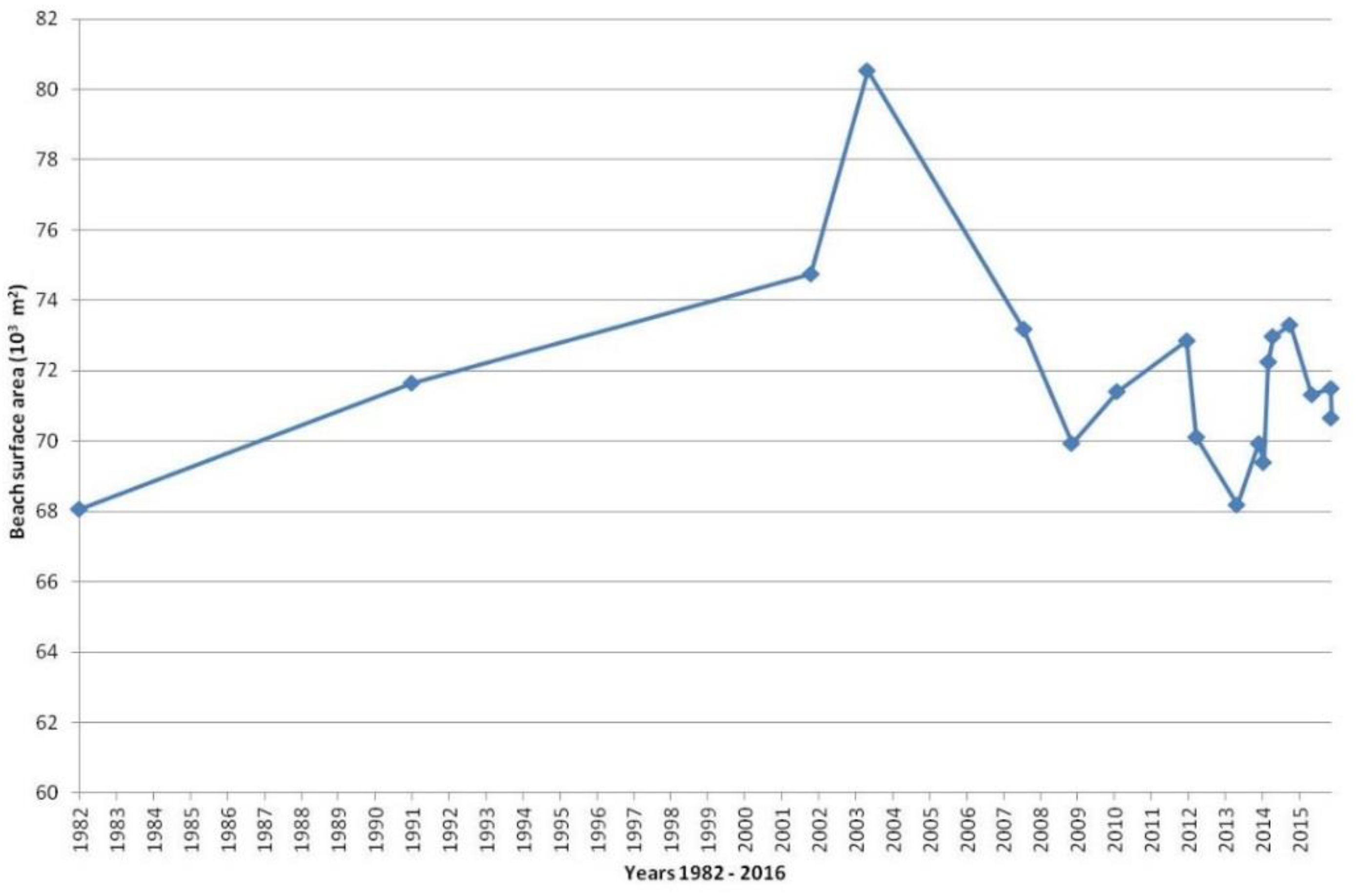
The satellite and aerial imagery analysis shows that the northernmost shore of Rhodes Island has slightly changed over the past 34 years, that is an annual increase of about 76 m2 with an uncertainty of ±520 m2/year (Figure 5). However, large variations have been identified in shorter period times, (Table 3), indicating that both accretion and erosion phenomena take place along the coast. The shoreline progradates in some parts of the beach and retreats in others, depending on the angle of incidence and height of approaching waves.
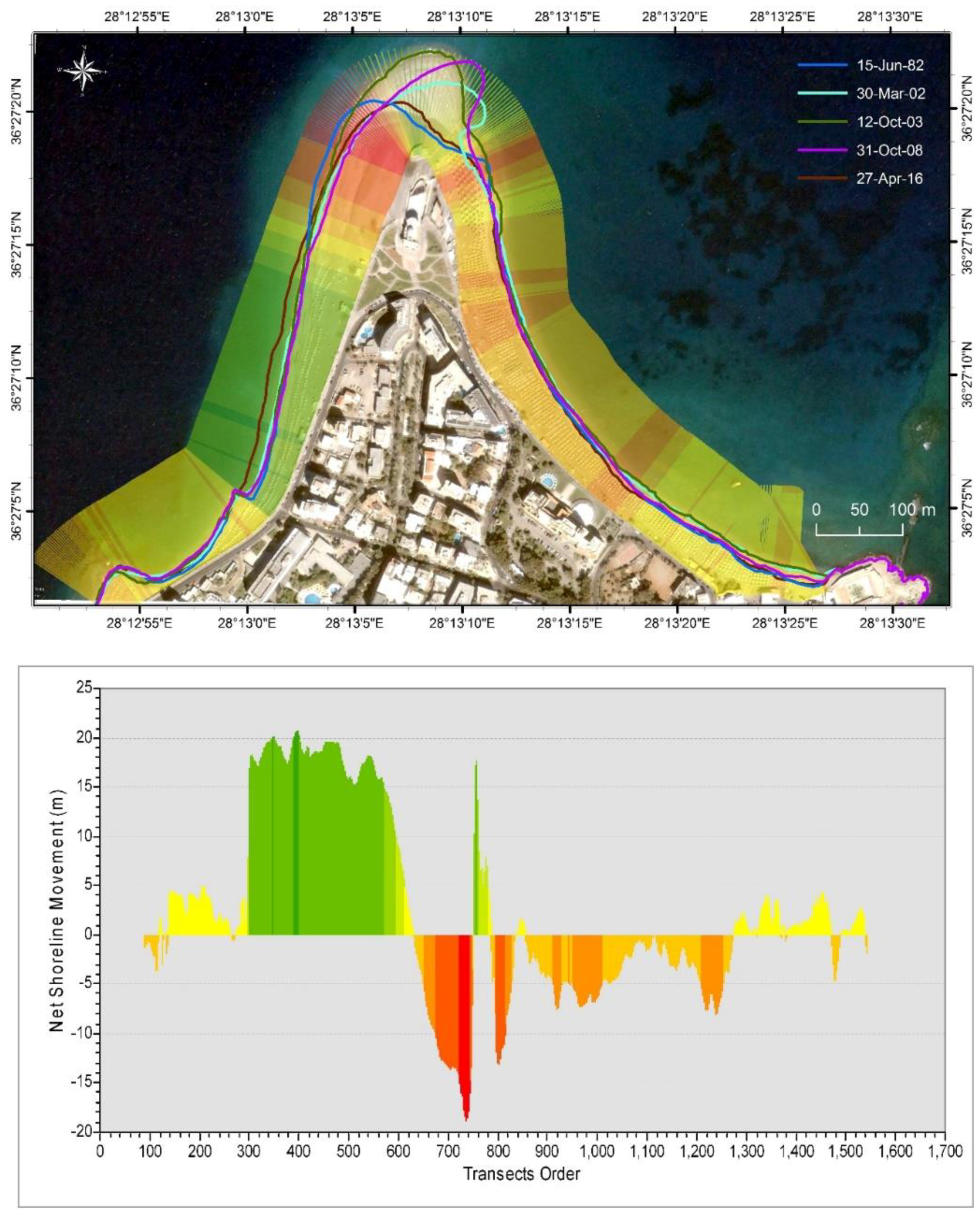
The shoreline displacement varies from a few decimeters to several tens of meters. The maximum shoreline advance is around 97 m detected in the period between 15 June 1982 and 31 October 2008, while the maximum shoreline retreat is around 35 m recorded from 15 June 1982 to 16 March 2015. The part of the beach that is most prone to extreme changes is the spit-like formation at the tip of the headland. The western part is also susceptible to accretion/erosion phenomena, while the eastern part seems to be less variable (Figure 6).
The temporal variability of shoreline position appears to be of sub-seasonal timescale, varying even often within the time window of a couple of months.

4.2. Morphodynamic Pattern

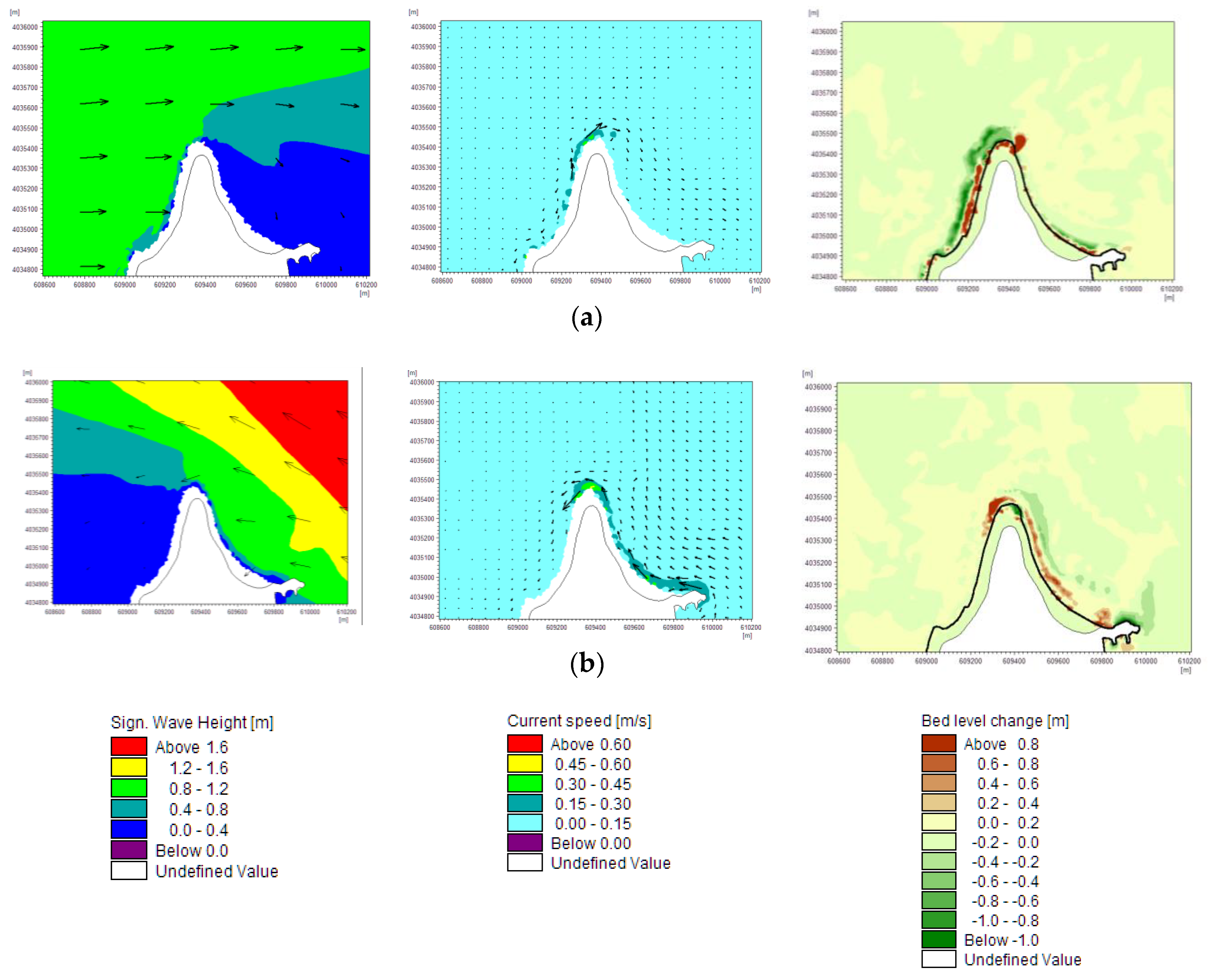
The simulation results show that wave height and direction change as waves propagate towards the shore due to shoaling and refraction. The prevailing western sector waves, occurring from SW, W, and NW directions (i.e., Scenarios 1, 2, and 4), induce a northward longshore drift in the western part of the study area, while SE waves (i.e., Scenario 3) result in northward sediment transport in the eastern part of the coast (Figure 7). The SE waves are of high-energy and occur mainly during the winter. The highest values of the current speed have been estimated around the headland (with a maximum value of 0.65 m/s in case of NW wave scenario) as this sector is characterized of high wave energy. The rest part of the coastal area is characterized by lower values of current speed, reaching up to 0.45 m/s. Due to these processes sediment is transported and deposited in the northern part of the coast, Cape Mylon, where a spit is formed. The spit direction changes gradually, depending on the wave and current conditions, namely it bends east due to W waves or west when strong SE wave events occur. According to Figure 7, positive seabed level change, denoting accretion, has been calculated along the west and east shoreface and negative change, denoting erosion, in greater depths (d > 2.5 m) (the solid black line in Figure 7 depicts the shoreline). The maximum seabed level change occurs due to SW wave scenario (Scenario 1); in this case erosion and accretion rates have been estimated of the order of 0.7 m and 1.0 m, respectively, in the west coast. Regarding the tip of headland, the corresponding values have been estimated 0.7 m and 2.4 m. However, slight erosion or accretion occurs along the eastern shoreface; in particular, seabed shifts corresponding to western sector waves simulations (Scenarios 1, 2 and 4) have been estimated to be about 72–87% smaller than in the west coast. In contrast, the simulation of SE wave scenario (i.e., Scenario 3) has resulted in greater morphological changes in the east coast (of the order of ±0.27 m) comparing to the west (where erosion and accretion rates have been estimated to be about 0.06 m and 0.03 m, respectively). In this wave scenario, seabed level changes at the northern sector of headland are −0.6 m (erosion) and 0.5 m (deposition). As bed level change values have been estimated less in the east side of the headland, this sector can be characterised as less variable.

5. Discussion

The diachronic analysis of shoreline evolution in the northern headland of the Rhodes Island shows that the overall beach surface has slightly changed since 1982, with a mean rate of 76 m2/year and an uncertainty of ±520 m2/year. In such a curved landform, wave energy distribution varies along the shoreline inducing also changes in longshore sediment transport, as it has been mentioned by López et al. [49,50] on different curvilinear coasts in Europe. Both accretion and erosion phenomena take place along the coast. Shoreline displacement rates are also higher in the western part of the headland comparing to the eastern sector, which has been estimated to be less variable. This happens due to different natural forcing factors (i.e., wave and current conditions) and morphological features (i.e., seabed slope) occurring alongshore. For example, a narrow erosional zone in an area with steep bed slope (in the western sector of the headland) is in agreement with López-Ruiz et al.’s [50] results obtained from simulation of a weakly curvilinear sandy beach.
However, the part of the beach that is the most variable is the spit-like formation at the tip of the headland (Figure 6). The shape and orientation of the spit-like beach depends almost exclusively on the height and angle of incidence of the approaching waves. More specifically, the coast alignment changes seasonally, due to variations in the annual wave regime, as it happens in areas with well-defined seasonal wind patterns, such as in North Carolina (USA) [51] and central Chile [52]. West sector waves cause deposition of coarse-grained material at the eastern sector of the spit, whereas southeast wave conditions favor accretion at the west sector, inducing an asymmetrical shape. The asymmetrical development of headland-associated sandbanks has been also estimated by Guillou and Chapalain [28], who applied a morphological model to an idealised Gaussian shaped headland. Although the probability of occurrence of extreme events from southeast is low (about 0.3%) they produce significant morphological changes due to high wave energy. These bed level shifts during the annual cycle have also been referred by Kombiadou et al. [34] in the same site, indicating that there is a balance in the annual cycle of sediment transport regime. The longshore sediment transport, which is the dominant component of littoral drift occurs up to 4 m depth (in the surf zone) and there is no significant loss in greater depths.
Winds are the main factor that determines the oceanographic regime in the coastal zone under investigation. The study area is classified as a micro-tidal coast like most coastal systems in the Mediterranean Sea [53], with a tidal range less than 15 cm, and therefore, tides cannot affect the wave-dominated pattern as it happens in the meso-tidal areas of Colombian Pacific coast [30] and macro-tidal settings of southern and southwestern UK [18,20].
The loss of small amounts of sediment from the shoreface during strong storms as well as the seasonal shoreline retreat can be mitigated by beach nourishment [54]. This soft engineering technique can maintain the beach width in specific parts of the headland providing aesthetic and environmental benefits. In contract, hard engineering options are not proposed, since they can have adverse effects on the sediment transport and beach self-adjustment. For adequate planning, design and implementation of coastal protection works, a close collaboration between engineers, scientists and stakeholders is required. Moreover, the application of a numerical model for the evaluation of such a project [55] and the prediction of shoreline evolution is suggested.

6. Conclusions

The analysis of historical shoreline displacement using multi-temporal aerial and satellite imagery reveals that although the case study area has experienced a slight change during the past 34 years (1982–2016), and significant retreat has been identified in shorter time periods. The most variable sector of the study area is the spit-like beach at the northern tip of Cape Mylon. Moreover, DSAS analysis points out greater rates of shoreline change in the western sector of the case study area comparing to the eastern, which seems to be less variable.
Morphological changes of this coastal zone and the spit-like formation at the headland result from complex coastal processes, such as wave-induced currents. More specifically, it is the longshore component of nearshore circulation that mainly controls littoral drift and sediment transport regime. Wave-induced currents are directed from the western and eastern sector to the tip of headland, where sediments are moved and deposited, forming a sandy spit-like beach. This spit-like morphology changes seasonally due to variations in the annual wave regime; it bends east due to mode western sector waves or west during the winter, when extreme waves propagate from the southeast.
Thus, the results based on both historical shoreline evolution and wave-current modelling highlight the cause–effect relationship among geomorphology, hydrodynamic conditions, sediment regime, and accretion and erosion processes in a curved planform. Moreover, the understanding of the involved natural processes is a major concern in coastal management, particularly in such a touristic region, that helps planners to propose appropriate measures for mitigating seasonal shoreline retreat.

Author Contributions

Conceptualization, F.-K.G. and V.K.; Methodology, F.-K.G., V.L. and P.D.; Software, F.-K.G., V.L. and P.D.; Validation, F.-K.G. and P.D.; Formal Analysis, F.-K.G., G.-A.H., P.D. and V.L.; Investigation, F.-K.G., G.-A.H. and S.D.; Resources, F.-K.G. and S.D.; Data Curation, F.-K.G., G.-A.H., S.D., P.D. and V.L.; Writing-Original Draft Preparation, F.-K.G., G.-A.H., V.K., V.L. and P.D.; Writing-Review & Editing, F.-K.G. and V.K.; Visualization, F.-K.G., G.-A.H., A.S. and V.K.; Supervision, V.K.; Project Administration, A.S. and V.K.; Funding Acquisition, A.S. and G.-A.H.

Funding

This research was funded by the Hydrobiological Station of Rhodes (Hellenic Centre for Marine Research) grant number [08.8800003/000] and GLAFKI – “Blue growth with innovation and application to the Greek Seas” program [MIS 5002438] (funded by the National Strategic Reference Framework)”.

Acknowledgments

The authors are grateful to three anonymous reviewers for their insightful comments that greatly improved the manuscript. F-K. Gad is also thankful to colleagues F. Karathanasi and D. Vandarakis for fruitful conversations.

Conflicts of Interest

The authors declare no conflict of interest.

References

  1. Dan, S.; Stive, M.J.F.; Walstra, D.-J.R.; Panin, N. Wave climate, coastal sediment budget and shoreline changes for the Danube Delta. Mar. Geol. 2009, 262, 39–49. [Google Scholar] [CrossRef]
  2. Kaliraj, S.; Chandrasekar, N.; Magesh, N.S. Impacts of wave energy and littoral currents on shoreline erosion/accretion along the south-west coast of Kanyakumari, Tamil Nadu using DSAS and geospatial technology. Environ. Earth Sci. 2014, 71, 4523–4542. [Google Scholar] [CrossRef]
  3. Komar, P.D. Beach Processes and Sedimentation, 2nd ed.; Prentice Hall: Upper Saddle River, NJ, USA, 1998. [Google Scholar]
  4. Dalrymple, R.A.; MacMahan, J.H.; Reniers, A.J.H.M.; Nelko, V. Rip currents. Annu. Rev. Fluid Mech. 2011, 43, 551–581. [Google Scholar] [CrossRef]
  5. Leatherman, S.P.; Zhang, K.; Douglas, B.C. Sea level rise shown to drive coastal erosion. Eos. Trans. Am. Geophys. Union 2000, 81, 55–57. [Google Scholar] [CrossRef]
  6. Williams, S.J. Sea-level rise implications for coastal regions. J. Coast. Res. 2013, 63, 184–196. [Google Scholar] [CrossRef]
  7. Bray, M.J.; Carter, D.J.; Hooke, J.M. Littoral cell definition and budgets for central southern England. J. Coast. Res. 1995, 381–400. [Google Scholar]
  8. Hapke, C.J.; Lentz, E.E.; Gayes, P.T.; McCoy, C.A.; Hehre, R.; Schwab, W.C.; Williams, S.J. A review of sediment budget imbalances along Fire Island, New York: Can nearshore geologic framework and patterns of shoreline change explain the deficit? J. Coast. Res. 2010, 510–522. [Google Scholar] [CrossRef]
  9. Cowell, P.J.; Thom, B.G. Morphodynamics of Coastal Evolution; Cambridge University Press: Cambridge, UK; New York, NY, USA, 1994. [Google Scholar]
  10. Bird, E.C.F. Coastal Geomorphology: An Introduction; John Wiley & Sons: New York, NY, USA, 2011; ISBN 1119964350. [Google Scholar]
  11. Woodroffe, C.D. Coasts: Form, Process and Evolution; Cambridge University Press: New York, NY, USA, 2002; ISBN 0521011833. [Google Scholar]
  12. Lambeck, K.; Antonioli, F.; Anzidei, M.; Ferranti, L.; Leoni, G.; Scicchitano, G.; Silenzi, S. Sea level change along the Italian coast during the Holocene and projections for the future. Quat. Int. 2011, 232, 250–257. [Google Scholar] [CrossRef]
  13. Kapsimalis, V.; Poulos, S.E.; Karageorgis, A.P.; Pavlakis, P.; Collins, M. Recent evolution of a Mediterranean deltaic coastal zone: Human impacts on the Inner Thermaikos Gulf, NW Aegean Sea. J. Geol. Soc. London 2005, 162, 897–908. [Google Scholar] [CrossRef]
  14. Aouiche, I.; Daoudi, L.; Anthony, E.J.; Sedrati, M.; Ziane, E.; Harti, A.; Dussouillez, P. Anthropogenic effects on shoreface and shoreline changes: Input from a multi-method analysis, Agadir Bay, Morocco. Geomorphology 2016, 254, 16–31. [Google Scholar] [CrossRef]
  15. David, T.I.; Mukesh, M.V.; Kumaravel, S.; Sabeen, H.M. Long-and short-term variations in shore morphology of Van Island in gulf of Mannar using remote sensing images and DSAS analysis. Arab. J. Geosci. 2016, 9, 756. [Google Scholar] [CrossRef]
  16. Ashton, A.D.; Murray, A.B. High angle wave instability and emergent shoreline shapes: 1. Modeling of sand waves, flying spits, and capes. J. Geophys. Res. Earth Surf. 2006, 111, F4. [Google Scholar] [CrossRef]
  17. Berthot, A.; Pattiaratchi, C. Mechanisms for the formation of headland-associated linear sandbanks. Cont. Shelf Res. 2006, 26, 987–1004. [Google Scholar] [CrossRef]
  18. Thomas, T.; Lynch, S.K.; Phillips, M.R.; Williams, A.T. Long-term evolution of a sand spit, physical forcing and links to coastal flooding. Appl. Geogr. 2014, 53, 187–201. [Google Scholar] [CrossRef]
  19. Goodwin, I.D.; Freeman, R.; Blackmore, K. An insight into headland sand bypassing and wave climate variability from shoreface bathymetric change at Byron Bay, New South Wales, Australia. Mar. Geol. 2013, 341, 29–45. [Google Scholar] [CrossRef]
  20. Bastos, A.; Collins, M.; Kenyon, N. Water and sediment movement around a coastal headland: Portland Bill, Southern UK. Ocean Dyn. 2003, 53, 309–321. [Google Scholar] [CrossRef]
  21. Ashton, A.D.; Nienhuis, J.; Ells, K. On a neck, on a spit: Controls on the shape of free spits. Earth Surf. Dyn. 2016, 4, 193. [Google Scholar] [CrossRef]
  22. Kumar, A.; Narayana, A.C.; Jayappa, K.S. Shoreline changes and morphology of spits along southern Karnataka, west coast of India: A remote sensing and statistics-based approach. Geomorphology 2010, 120, 133–152. [Google Scholar] [CrossRef]
  23. Thomas, T.; Phillips, M.R.; Williams, A.T. Mesoscale evolution of a headland bay: Beach rotation processes. Geomorphology 2010, 123, 129–141. [Google Scholar] [CrossRef]
  24. Esteves, L.S.; Williams, J.J.; Dillenburg, S.R. Seasonal and interannual influences on the patterns of shoreline changes in Rio Grande do Sul, southern Brazil. J. Coast. Res. 2006, 1076–1093. [Google Scholar] [CrossRef]
  25. Pethick, J.S.; Crooks, S. Development of a coastal vulnerability index: A geomorphological perspective. Environ. Conserv. 2000, 27, 359–367. [Google Scholar] [CrossRef]
  26. Boak, E.H.; Turner, I.L. Shoreline definition and detection: A review. J. Coast. Res. 2005, 688–703. [Google Scholar] [CrossRef]
  27. Lakhan, V.C. Advances in Coastal Modeling. Elsevier Oceanography Series; Elsevier Science & Technology: New York, NY, USA, 2003; ISBN 1281054801. [Google Scholar]
  28. Guillou, N.; Chapalain, G. Effects of waves on the initiation of headland-associated sandbanks. Cont. Shelf Res. 2011, 31, 1202–1213. [Google Scholar] [CrossRef]
  29. Belibassakis, K.A.; Karathanasi, F.E. Modelling nearshore hydrodynamics and circulation under the impact of high waves at the coast of Varkiza in Saronic-Athens Gulf. Oceanologia 2017, 59, 350–364. [Google Scholar] [CrossRef] [Green Version]
  30. Martinez, J.O.; Pilkey, O.H.; Neal, W.J. Rapid formation of large coastal sand bodies after emplacement of Magdalena river jetties, Northern Colombia. Environ. Geol. Water Sci. 1990, 16, 187–194. [Google Scholar] [CrossRef]
  31. Anagnostou, C.; Antoniou, P.F.; Hatiris, G.A. Erosion of a depositional coast in NE Rhodos island (SE Greece) and assessment of the best available measures for coast protection. J. Coast. Res. 2011, 64, 1316–1319. [Google Scholar]
  32. Hatiris, G.A.; Kapsimalis, V.; Rousakis, G.; Panagiotopoulos, I.; Kyriakidou, H.; Morfis, I.; Kondylatos, G.; Anagnostou, C.; Sioulas, A. Morphometric Characteristics of Submarine Canyons on the Eastern Continental Shelf of Rhodes Island and İnsights on Their Generating Mechanisms. In Proceedings of the 11th Panhellenic Symposium of Oceanography & Fisheries, Mytilene, Greece, 13–17 May 2015. [Google Scholar]
  33. Verikiou-Papaspiridakou, E.; Bathrellos, G.; Skilodikou, H. Physico-geographical observations of the coastal zone of the northeastern part of Island Rhodes. Bull. Geol. Soc. Greece 2004, 36, 958–967. [Google Scholar]
  34. Kombiadou, K.; Chatiris, G.A.; Androulidakis, G.; Sioulas, A.; Krestenitis, G.; Anagnostou, C.; Issaris, G. Investigation of erosion at the cape of Rhodos and defence measures. In Proceedings of the 9th Symposium on Oceanography & Fisheries, Patras, Greece, 13–16 May 2009; Volume 1, pp. 178–183. [Google Scholar]
  35. Soukissian, T.; Hatzinaki, M.; Korres, G.; Papadopoulos, A.; Kallos, G.; Anadranistakis, E. Wind and Wave Atlas of the Hellenic Seas; Hellenic Centre for Marine Research: Anavyssos, Greece, 2007; ISBN 978960866519-4. [Google Scholar]
  36. Hellenic Hydrographic Service. Statistical Data of Sea Level at Greek Ports; Hydrographic Service, Hellenic Army Navy: Athens, Greece, 2013. [Google Scholar]
  37. Pytharouli, S.I.; Stiros, S.C. Analysis of short and discontinuous tidal data: A case study from the Aegean Sea. Surv. Rev. 2012, 44, 239–246. [Google Scholar] [CrossRef]
  38. Google Earth V 7.3.1.4507. Cape Mylon, Rhodes, Greece. Lat: 36.455364N, Lon: 28.220384E. Eye alt 897 m. DigitalGlobe 30/03/2002-03/09/2012 & 14/05/2014-21/04/2016, CNES/Airbus 09/10/2013 & 27/04/2016. Available online: http://www.google.com/earth (accessed on 3 September 2016).
  39. Di Stefano, A.; De Pietro, R.; Monaco, C.; Zanini, A. Anthropogenic influence on coastal evolution: A case history from the Catania Gulf shoreline (eastern Sicily, Italy). Ocean Coast. Manag. 2013, 80, 133–148. [Google Scholar] [CrossRef]
  40. Malarvizhi, K.; Kumar, S.V.; Porchelvan, P. Use of High Resolution Google Earth Satellite Imagery in Landuse Map Preparation for Urban Related Applications. Procedia Technol. 2016, 24, 1835–1842. [Google Scholar] [CrossRef]
  41. Martin, D.; Jones, R. What Transformation ? Appropriate Transformations for Georeferencing Scanned Maps in ArcGIS; Helyx Secure information Systems Ltd.: Gloucestershire, UK, 2015; p. 23. [Google Scholar]
  42. Nave, S.; Rebêlo, L. High-resolution geological cartography and coastal evolution assessment at Armação de Pêra–Galé sector: A prototype for a national coastal mapping. J. Coast. Conserv. 2018, 1–13. [Google Scholar] [CrossRef]
  43. Morton, R.A. National Assessment of Shoreline Change: Part 1: Historical Shoreline Changes and Associated Coastal Land Loss along the US Gulf of Mexico; Diane Publishing: Darby, PA, USA, 2008; ISBN 1437902596. [Google Scholar]
  44. Fletcher, C.H.; Romine, B.M.; Genz, A.S.; Barbee, M.M.; Dyer, M.; Anderson, T.R.; Lim, S.C.; Vitousek, S.; Bochicchio, C.; Richmond, B.M. National Assessment of Shoreline Change: Historical Shoreline Change in the Hawaiian Islands; Open-File Report 2011–1051; U.S. Geological Survey: Reston, Virginia, USA, 2011.
  45. Thieler, E.R.; Himmelstoss, E.A.; Zichichi, J.L.; Ergul, A. The Digital Shoreline Analysis System (DSAS) Version 4.0-An ArcGIS Extension for Calculating Shoreline Change; US Geological Survey: Tallahassee, FL, USA, 2009.
  46. DHI. MIKE 21/3 Coupled Model FM, User Guide; Danish Hydraulic Institute: Hørsholm, Denmark, 2016. [Google Scholar]
  47. US Army Corps of Engineers. Chapter III-2, Longshore Sediment Transport, Engineer Manual 1110-2-1100. In US Army Corps of Engineers (USACE) Coastal Engineering Manual; US Army Corps of Engineers: Washington, DC, USA, 2006. [Google Scholar]
  48. Borah, D.K.; Balloffet, A. Beach evolution caused by littoral drift barrier. J. Waterw. Port Coast. Ocean Eng. 1985, 111, 645–660. [Google Scholar] [CrossRef]
  49. López-Ruiz, A.; Ortega-Sánchez, M.; Baquerizo, A.; Losada, M.A. Short and medium-term evolution of shoreline undulations on curvilinear coasts. Geomorphology 2012, 159, 189–200. [Google Scholar] [CrossRef]
  50. López-Ruiz, A.; Ortega-Sánchez, M.; Baquerizo, A.; Losada, M.Á. A note on alongshore sediment transport on weakly curvilinear coasts and its implications. Coast. Eng. 2014, 88, 143–153. [Google Scholar] [CrossRef]
  51. Park, J.-Y.; Wells, J.T. Longshore transport at Cape Lookout, North Carolina: Shoal evolution and the regional sediment budget. J. Coast. Res. 2005, 1–17. [Google Scholar] [CrossRef]
  52. Martínez, C.; Quezada, M.; Rubio, P. Historical changes in the shoreline and littoral processes on a headland bay beach in central Chile. Geomorphology 2011, 135, 80–96. [Google Scholar] [CrossRef]
  53. Sánchez-Arcilla, A.; Jiménez, J.A. Breaching in a wave-dominated barrier spit: The trabucador bar (north-eastern spanish coast). Earth Surf. Process. Landf. 1994, 19, 483–498. [Google Scholar] [CrossRef]
  54. Patsch, K.; Griggs, G. Littoral Cells, Sand Budgets, and Beaches: Understanding California’s Shoreline; Institute of Marine Sciences: Santa Cruz, CA, USA, 2006. [Google Scholar]
  55. Karambas, T.V; Samaras, A.G. Soft shore protection methods: The use of advanced numerical models in the evaluation of beach nourishment. Ocean Eng. 2014, 92, 129–136. [Google Scholar] [CrossRef]
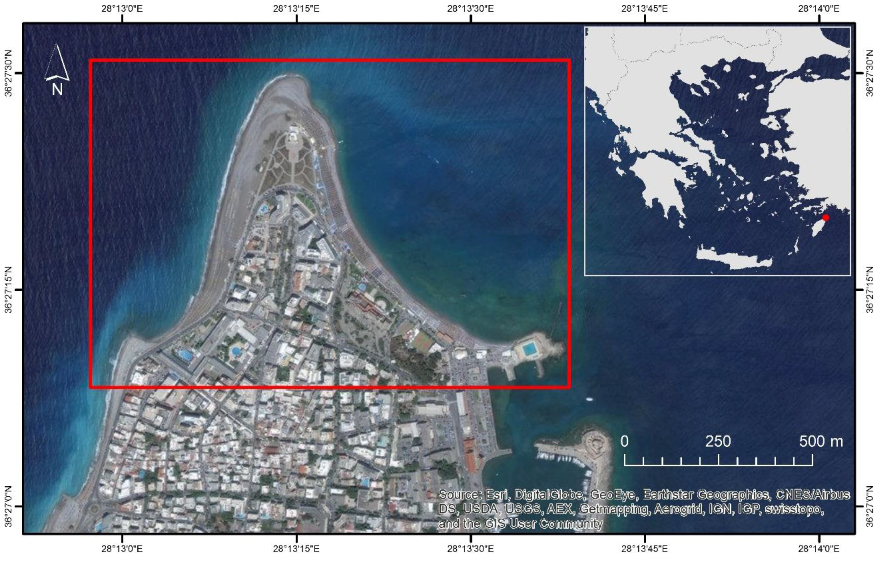
Figure 1. The study area of the Cape Mylon, Rhodes Island, Greece.
Water 10 00849 g001
Figure 2. Photographs showing the texture of surface sediment on (a) the subaerial beach; (b) the foreshore; and (c) shoreface.
Water 10 00849 g002
Figure 3. Rose diagrams offshore Rhodes Island, showing significant wave heights and mean wave directions, for the time period 1995–2004.
Water 10 00849 g003
Figure 4. Bathymetry of (a) the model domain and (b) the northern part of Rhodes Island, as well as the (c) computational mesh of the area of interest.
Water 10 00849 g004
Figure 5. Beach surface evolution (1982–2016).
Water 10 00849 g005
Figure 6. Long-term (1982–2016) shoreline analysis in DSAS model on both sides of the Cape Mylon.
Water 10 00849 g006
Figure 7. Wave field, littoral drift and bed level change simulation results of (a) SW wave scenario (Scenario 1: Hm0 = 1.25 m, Tp = 6.75, MWD = 255 degN) and (b) SE wave scenario (Scenario 3: Hm0 = 2.25 m, Tp = 6.75, MWD = 135 degN).
Water 10 00849 g007
Table 1. Reference to the original data sources.
DateTypeSourceScale/Resolution
15 June 1982Aerial photographHellenic Military Geographical Service1:8000
17 June 1991Aerial photographHellenic Military Geographical Service1:8000
30 March 2002Satellite ImageryQuickBird-267.28 cm
12 October 2003Satellite ImageryQuickBird-262.59 cm
31 October 2008Satellite ImageryOrthophotomaps of the Hellenic Cadastre50.00 cm
22 April 2009Satellite ImageryGeoEye-143.51 cm
16 July 2010Satellite ImageryGeoEye-142.99 cm
30 May 2012Satellite ImageryWorldView-247.28 cm
3 September 2012Satellite ImageryGeoEye-144.76 cm
9 October 2013Satellite ImageryPléiades-1A50 cm
14 May 2014Satellite ImageryWorldView-255.34 cm
29 June 2014Satellite ImageryWorldView-247.72 cm
17 August 2014Satellite ImageryWorldView-247.88 cm
2 October 2014Satellite ImageryWorldView-247.77 cm
16 March 2015Satellite ImageryGeoEye-147.22 cm
17 October 2015Satellite ImageryWorldView-333.61 cm
21 April 2016Satellite ImageryWorldView-248.24 cm
27 April 2016Satellite ImageryPléiades-1A50 cm
Table 2. Representative wave scenarios simulated for the assessment of sediment transport and morphological changes in the case study area (Hs: significant wave height (m), Tp: peak wave period (s), MWD: mean wave direction (deg N)).
ScenariosHs (m)Tp (s)MWD (deg N)Simulation Time (days)
Sc11.256.7525545
Sc21.255.2527039
Sc32.256.7513512
Sc41.755.253004
Table 3. DSAS results of shoreline displacement extremes.
ShorelineMax Advance (m)Max Retreat (m)Coastal Zone Surface (m2)Surface Evolution between Consecutive Shoreline Items (m2)Cumulative Surface Evolution (from 1982) (m2)Duration (y)
15 June 1982Shoreline of reference68,056.6Shoreline of reference
17 June 199140.9−15.571,651.93595.33595.39.01
30 March 200269.9−25.174,759.53107.66702.919.79
12 October 200391.6−20.080,526.85767.312,470.221.33
31 October 200897.1−25.473,191.4−7335.45134.725.54
22 April 200927.1−32.469,941.0−3250.41884.426.85
16 July 201059.0−25.071,413.91472.93357.328.09
30 May 201239.8−16.972,864.61450.84808.029.96
3 September 201251.2−17.170,106.3−2758.42049.730.22
9 October 201361.5−21.968,199.3−1906.9142.731.32
14 May 201437.8−33.969,923.71724.41867.131.91
29 June 201428.2−31.269,397.3−526.41340.732.04
17 August 201446.1−25.672,241.02843.74184.432.17
2 October 201457.3−29.772,967.5726.54910.932.30
16 March 201540.5−34.973,291.5324.05234.932.75
17 October 201564.7−28.871,329.4−1962.13272.833.34
21 April 201621.7−17.071,484.1154.73427.533.85
27 April 201620.8−18.970,655.0−829.12598.433.87