1. Introduction
The horizontally-framed miter gate is widely used for ship lock control devices in hydraulic engineering. With the rapid development of navigation in China, the applicable condition, operation mode and structural stress of the lock gate have attracted more and more public attention. Especially in recent years, a series of super-high-head ship locks in complex operating conditions has been built in the southwest of China. Therefore, it is necessary to carry out the related study of the miter gate for its safe and stable operation.
Nowadays, the research on miter gates mainly contributes to the structure stress or fatigue [
1,
2,
3,
4,
5,
6]. For example, Ming [
1] made a theoretical analysis of a miter-type lock gate structure subjected to hydrostatic pressure and found that the failure modes were decisively dependent on the mitered angle. Camporese [
2] used static equilibrium considerations for the preliminary dimensioning of miter gate leaves based on the optimization of the angle between the leaves and suggested appropriate angles. Riveros [
7] applied three-dimensional numerical simulation to study the optimum prestressing on diagonals in the miter gate, which allowed the prediction of optimum prestressing levels without compromising the torsional capacity. Eick et al. [
8] developed an automated damage detection system for miter gates of navigation locks, which can identify the redistribution of load throughout lock gates in the presence of damage. Mahmoud et al. [
9] used finite element Monte Carlo simulations to conduct probabilistic assessment of the propagation rate of cracks in miter gates, and the optimal inspection or repair schedule patterns could be obtained.
Besides, the hydrodynamic resistance should be taken into account during the opening and closing process of the miter gate. If the water surface is unsteady or over-filling (over-emptying) exists, the resistance will increase rapidly, which induces excessive load on the piston rod. For example, the piston rod of the miter gate was fractured by the pressure of reverse head in Gezhouba ship lock of China, and Xuan [
10] studied the optimization measures by physical model test. The research showed that opening the gate in a timely manner could decrease the reverse head. In addition, the operating resistance of the miter gate is influenced by many factors, which include the operating time, the operating cylinder size, the submergence, the under gate clearance, the operating machinery, and so on. Riveros [
7] concluded that the maximum value of the hydrodynamic load was equivalent to a resistance of 1.44 kPa on the submerged portion of the gate leaf. The U.S. Army Corps of Engineers summarized that gate machinery should be designed to withstand the forces produced by a 0.381-m (exceeding a 30-s duration) surge load acting on the submerged portion of the miter gate [
5]. All these results mentioned above are usually obtained by physical model or prototype test [
4].
To further explore the characteristics of the opening process in detail, some scholars adopted numerical methods to simulate the operation of the miter gate. For example, based on Navier–Stokes equations in polar coordinates, Lejeune [
11] studied the flow field of miter gate opening and closing by the curl-stream function method. Only the state of unit-thickness layer in the two-dimensional model was considered, and it could not illustrate the changes of water level on the two sides of the lock gate. Zheng [
12] advanced a three-dimensional model, which combined the finite element with the finite difference method. It could simulate the unsteady flow water level variation caused by the rotation of the miter gate successfully. The trend of resistance obtained from the model was consistent with the one of the physical model test, except for some error. Chen [
13] reviewed the research on the hydrodynamic resistance moment of the miter gate. The measured data of the miter gate in China were summarized. The effect of dynamic resistance by different submerged water depths, opening and closing time, gate form, under gate clearance and temporal loads were analyzed. It was found that the temporal loads caused by over-filling or over-emptying should be considered carefully in the designing of high head locks. In brief, to study the opening process and dynamic resistance from a quantitative perspective, it is essential to explore the opening process of the miter gate by an appropriate turbulence model with the dynamic mesh technique.
In this paper, the prototype test is introduced for the study of the operating load of horizontally-framed miter gates in the third line ship lock of Changzhou hydro-junction in China. Then, a three-dimensional numerical simulation model with dynamic mesh is established to study the opening process of the miter gate, and the hydrodynamic characteristics are analyzed under the different submerged depths and different reverse heads.
2. Prototype Test
Changzhou hydro-junction is an important navigation project in Xijiang River of China. It includes four ship locks and has the biggest traffic capacity in the world, as shown in
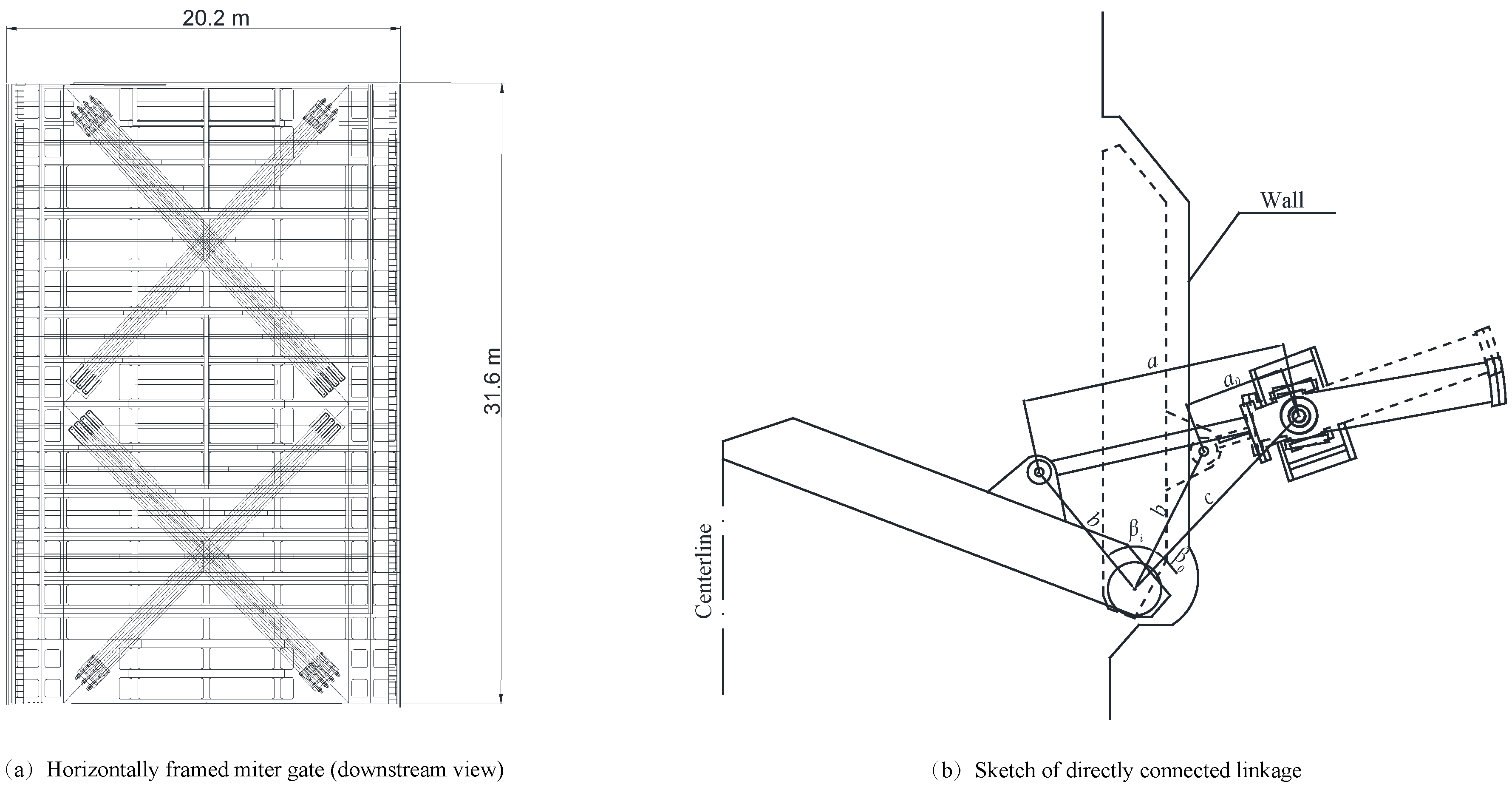
Figure 1. The effective dimensions of the newly built third line and fourth line ship locks as the length × width × depth on the sill are 340 m × 34 m × 5.8 m, and the cross-section of lock culvert is 4.6 m × 6.0 m. The dimensions of horizontally-framed miter gates in the upper and lower lock head are 20.2 m × 18.6 m, 20.2 m × 31.6 m (width × height), respectively. The gates are actuated by a directly-connected linkage, which consists of a cylinder mounted in a gimbal bracket and located in a recess on the lock wall with the piston rod. The elevation of the downstream lock bottom is −4.4 m. The maximum navigation water level in the downstream is 25.7 m. The minimum navigation water level in the downstream is 3.32 m. The angle between the leaf and the normal to the lock wall is
, as shown in
Figure 2.
As the scale of the miter gate is large and the inertia length of the lock culvert is long, overfilling or emptying is obvious during the operation. A prototype test in the third ship lock is conducted before the normal operation. The test includes two parts. One is in the hydrostatic condition, which is conducted with the gate opening or closing in still water, and the initial water level on both sides of gate is equal. The other is in the hydrodynamic condition, which is conducted after the filling or emptying process.
HQ100P oil pressure sensors are chosen to measure the hoisting load during the gate operation in the prototype test. The sensors have been calibrated in the laboratory and installed on the rod end and the head end of the cylinder, and the operating load can be calculated by the pressure difference between these two ends, shown in
Figure 3. The frequency acquisition is 10 Hz. The diameter and the rated loads are shown in
Table 1. The water level sensors are also mounted in the lock head to study water level fluctuation near the gate during the opening and closing process.
2.1. Hydrostatic Test
The measured opening time or closing time of the miter gate and the initial water level in the hydrostatic test are shown in
Table 2. From
Table 2, it can be seen that the opening time is less than the designed time, which is 200 s, and the closing time is near the designed time, which is 270 s. The opening and closing time meet the design requirement, and the left gate and right gate are close to being synchronous.
The pressure of the rod end and head end and hoisting load, which are calculated by these two pressures, are shown in
Table 3 and
Figure 4. From
Table 3 and
Figure 4, it can be seen that the load is basically stable during the opening process, except a small oscillation due to the influence of the mechanics. At the initial stage, there is a starting peak of the force acting on the piston rod. Then, the pressure tends to be more stable during the opening process. At the end of opening, the load is oscillated again, and the peak value is less than the starting peak. Generally, the hoisting load is less than the rated load, which is 1600 kN on the cylinder of the upper gate and 2600 kN on the cylinder of lower gate.
2.2. Hydrodynamic Test
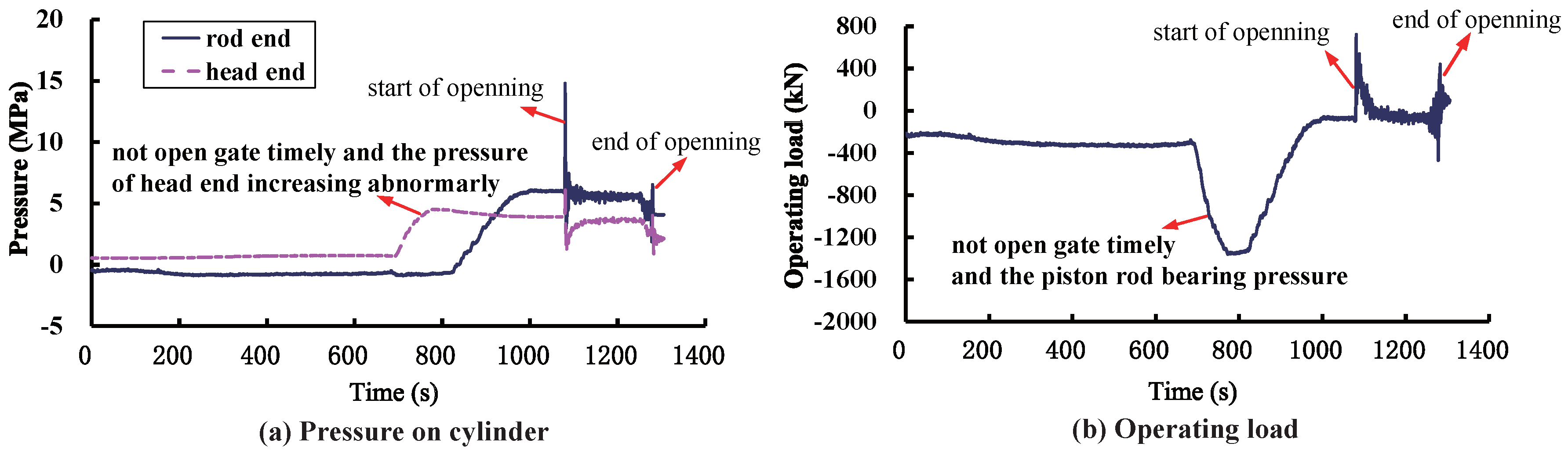
At the initial stage of the hydrodynamic test, water level gauges of the operating machinery are not mounted, and the operation is conducted by manual control. With manual control, the operator watches the water level at the two sides of the gate during the filling or emptying process and opens the gate when he/she considers that the water levels at the two sides of the gate are equal. In this condition, the miter gate cannot be guaranteed to open in a timely manner when the equal water levels occur the first time. The miter gates are compressed by reversed head. The measured data show that the reverse head is 0.5 m during the filling process and 0.42 m during the emptying process, as shown in
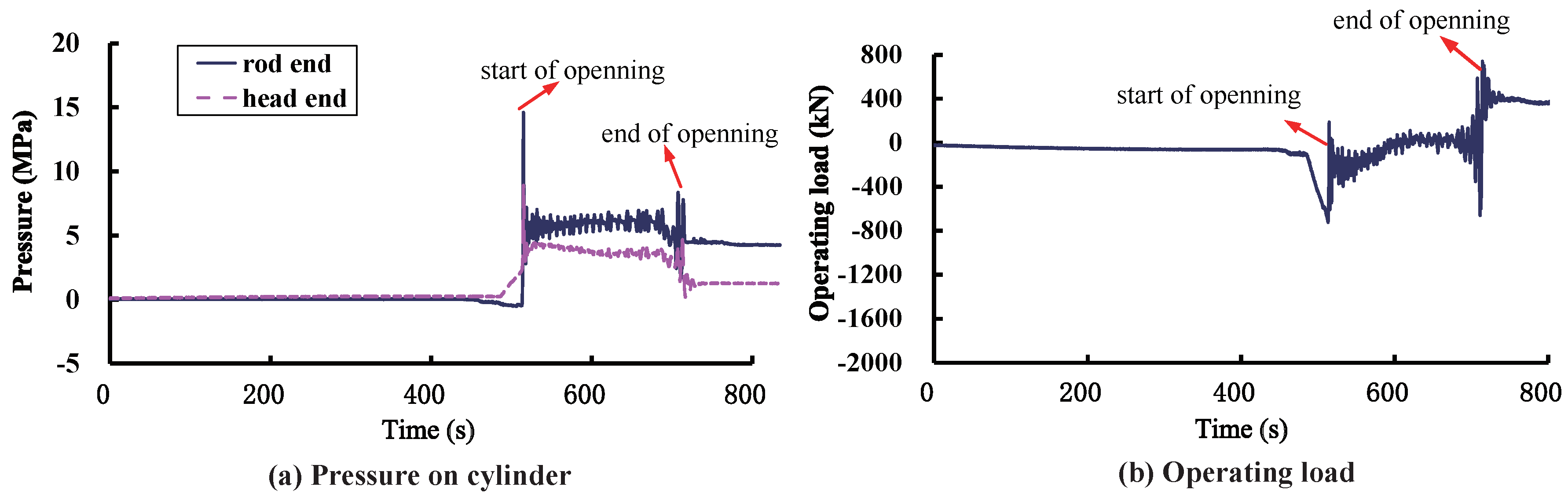
Table 4. After the water level gauge of the operating machinery is installed, the miter gates are opened in a timely manner, and the reverse head action on the gates at the opening reduces greatly, which is 0.14 m during the filling process and 0.16 m during the emptying process.
The measured opening time in the hydrodynamic test is close to the time of the hydrostatic test. The left-side and right-side gates are close to being simultaneous. The corresponding operating forces are shown in
Table 5 and
Figure 5 and
Figure 6.
From
Table 5,
Figure 5 and
Figure 6, it can be found that the variation of operating forces is like a saddle-shaped curve. The instantaneous load on the piston rod is strong at the beginning and end of operation. It remains weak during the operation process. Although the load acting on the cylinder meets the rated value, the reverse head will result in great force acting on the piston rod if the gates are not opened in a timely manner. As the safety margin is inadequate, the value of the starting peak may exceed the rated oil pressure if the gate is operating under high submergence.
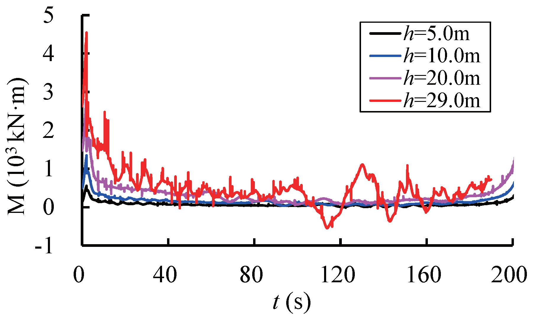
The prototype test is conducted during the dry season, and the submerged depths in the upper gate and lower gate are only 7.7 m and 9.9 m. These are 59% and 33% of the maximum submerged depth, which are calculated with the highest navigational water level of 25.79 m in the upstream and 27.70 m in the downstream, respectively. In order to explore the operation characteristics under the condition of high submerged depth, a three-dimensional numerical simulation is applied for further study.
3. Numerical Model
The numerical simulation is performed with FLUENT, a commercial general-purpose CFD package supplied by ANSYS Inc (Canonsburg, PA, USA). The RNG turbulent model is used for the closure in the controlling equations. The numerical techniques used in this paper are shown as follows.
3.1. Volume of Fluid Model
The volume of fluid (VOF) model is used to capture the water-vapor interface. The free surface is defined as an isosurface where the function value is zero. The water, or gas, or a mixture has the same velocity and submits to the same moment equations in the same unit.
The volume fractions of water and gas in the field are regarded as separate variables. In each cell, the total volume fraction of water and gas is one, that is
, where
and
represent the volume fractions of water and gas. The density and viscosity coefficient of each cell can be described as the weighted average of volume fractions.
In the equations, and represent the density of water and gas, and and represent the viscosity coefficient of water and gas, respectively.
3.2. Discretization Scheme
The finite volume method is introduced for the discretization of the governing equation, where the two-order upwind scheme is used for the convection term, and the central difference scheme is adopted for the diffusion term. The pressure implicit with splitting of operator (PISO) algorithm is employed for the pressure-velocity coupling.
3.3. Dynamic Mesh
A spring-based smoothing method and a 2.5-D remeshing technique are applied to accommodate the moving body in the discretized computational domain [
14,
15]. The opening process depends on the layout of the operating machinery and operating mode. The angular velocity of the miter gate
can be shown as:
in which
is the angular velocity,
s is the stroke of the piston rod,
is the revolving angular of gate, which varies form
–
,
is the distance from the gimbal bracket to the clevis, which connects the piston rod to the gate when the gate is in the recessed position,
b is the distance from the rotating shaft of the gate to the clevis,
c is the distance from the gimbal bracket to the rotating shaft and
is the angle between
b and
c when the miter gate is in the process position, as shown in
Figure 2. The opening time is set as 200 s, in which the period of 1–2 s is the acceleration process, 2–198 s is in a constant velocity (with a piston velocity 0.0325 ms
−1) and 198–200 s is the deceleration process.
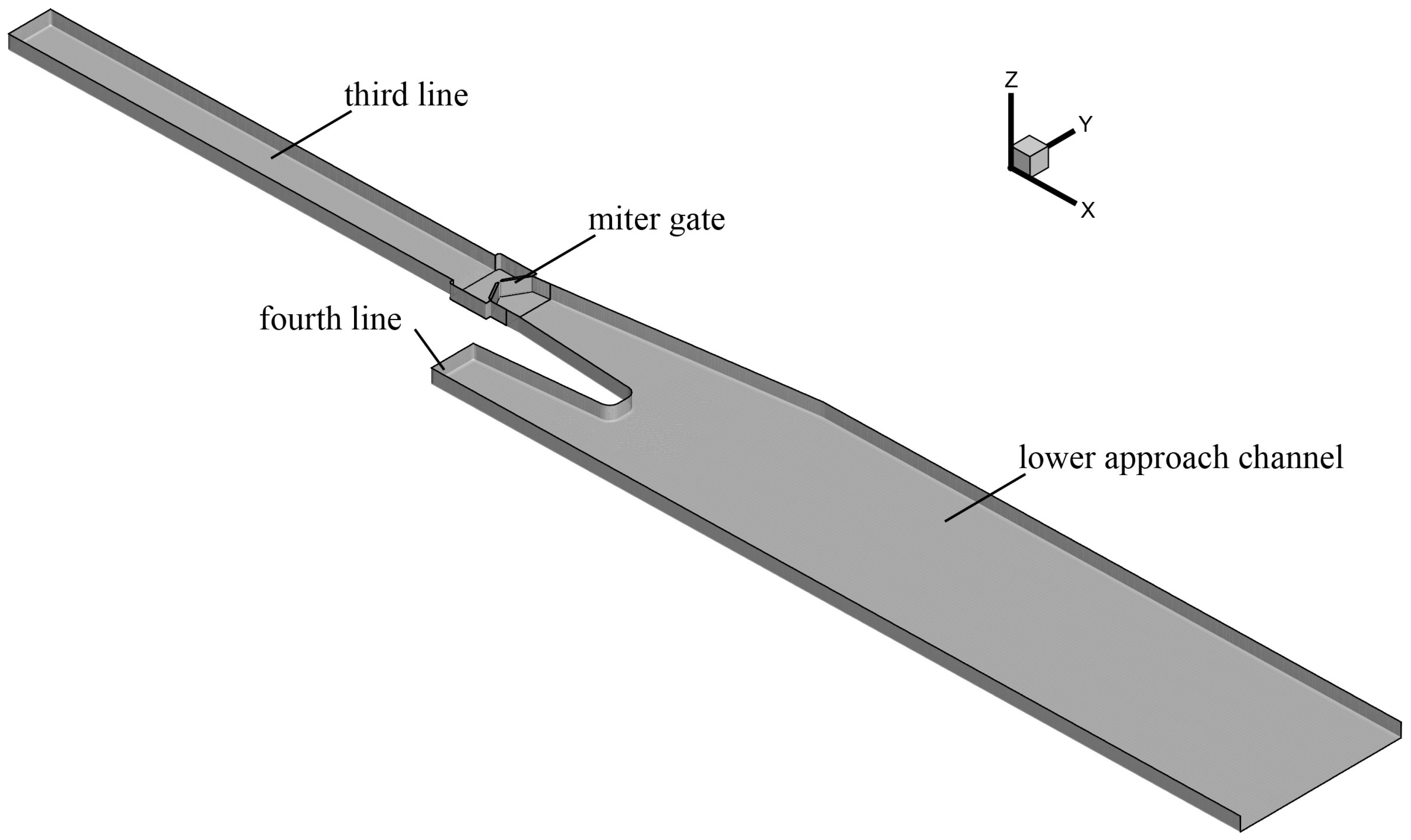
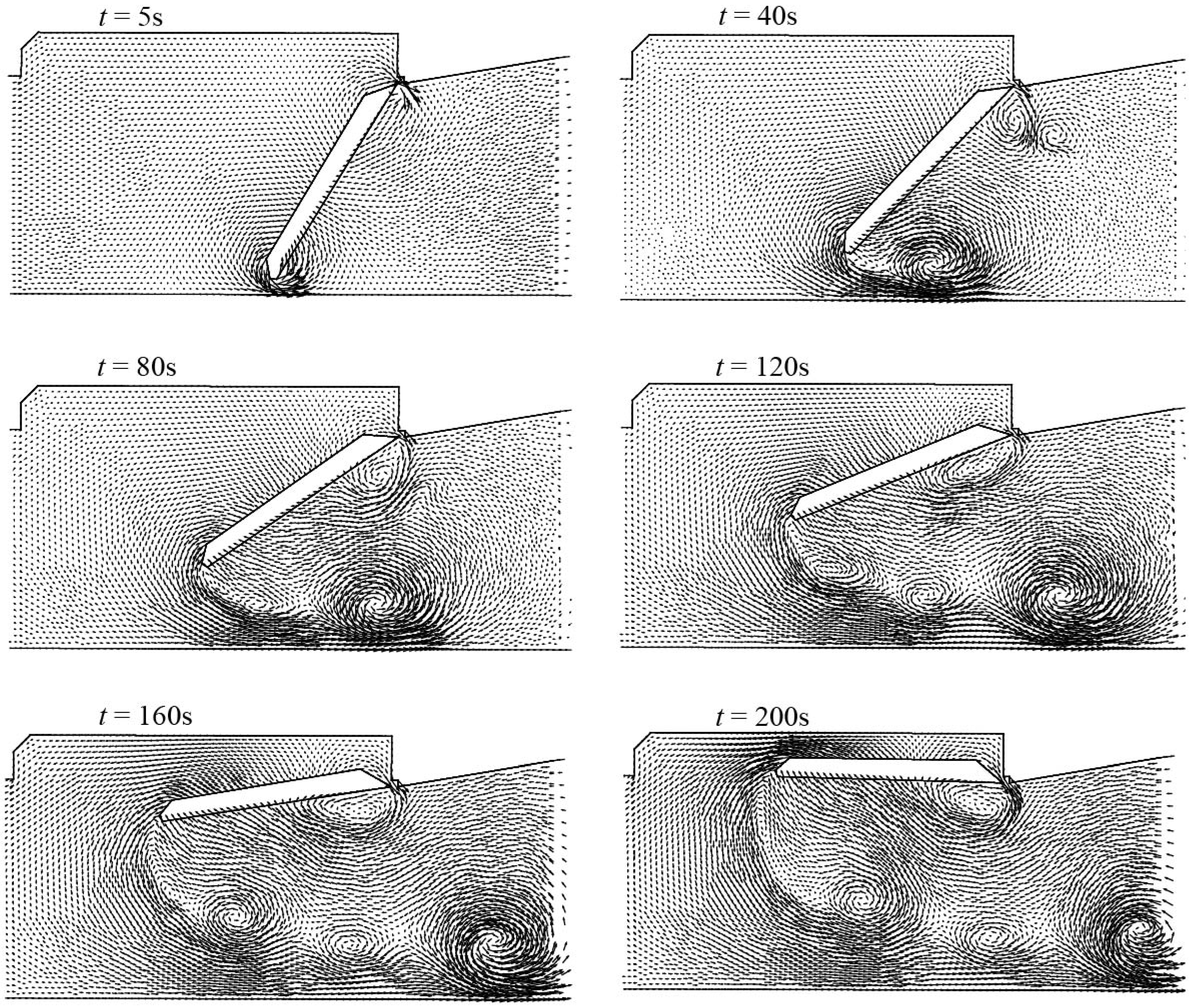
The numerical model including the ship lock and lower approach channel is shown in
Figure 7. The gates are simulated as a rigid body approximately, and the transformation of the mesh during the opening process in the lower lock head is shown in
Figure 8.
The proposed model is applied to study the hydrodynamic characteristics of the lower lock head during the opening process. For simplification, the effect of under gate clearance is not taken into consideration in the numerical model.
3.4. Model Verification
The results of prototype observation are applied for model verification. In the verification condition, the water levels of the lock chamber inside and outside are both 5.4 m; the submergence depths at the two sides of gate are both 9.8 m; and the opening time of the miter gate is 200 s. Resistance moment
is measured and calculated in the numerical simulation.
includes two parts: one is caused by water pressure
, and the other is induced by viscosity. It can be calculated as follows.
in which:
and
represent the pressure of the
x component and
y component on the gate.
and
are the viscous components of the
x direction and
y direction;
is the area of the gate;
is the coordinate of the vertical rotational axis;
represents the coordinate on the surface of the gate. The dynamic resistance moment is integrated by pressure on the surface of the gate.
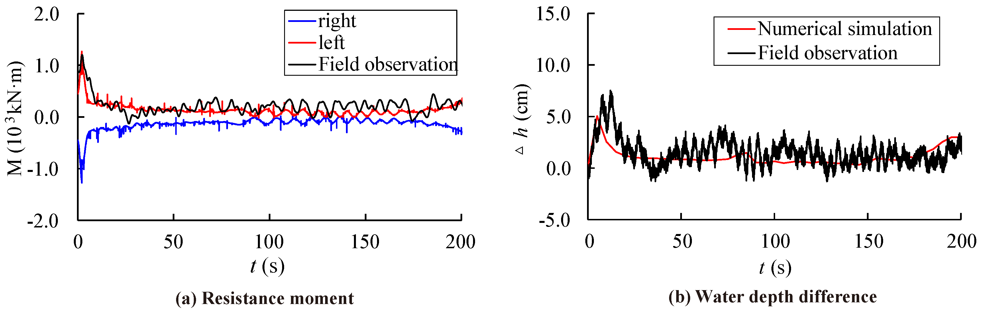
The comparison of the resistance moment and submergence depth difference on the two sides of the gate between prototype observation and numerical simulation is shown in
Figure 9. It can be seen that the resistance moment and submergence depth difference are basically consistent, while the oscillation value of the prototype observation is a little greater than that of the numerical simulation. It seems that there are many uncertain influencing factors existing in the prototype observation, such as the oscillation of the mechanical machinery at the initial time, the unsteady friction resistance during the opening process, the small fluctuation of the water surface near the gate, and so on. It also can be found that the absolute values of the left and right side are almost equal, such that it can be concluded that the asymmetric topography of the downstream has no influence on the hydrodynamic resistance moment. The above shows that the numerical simulation method is feasible and the results are credible.
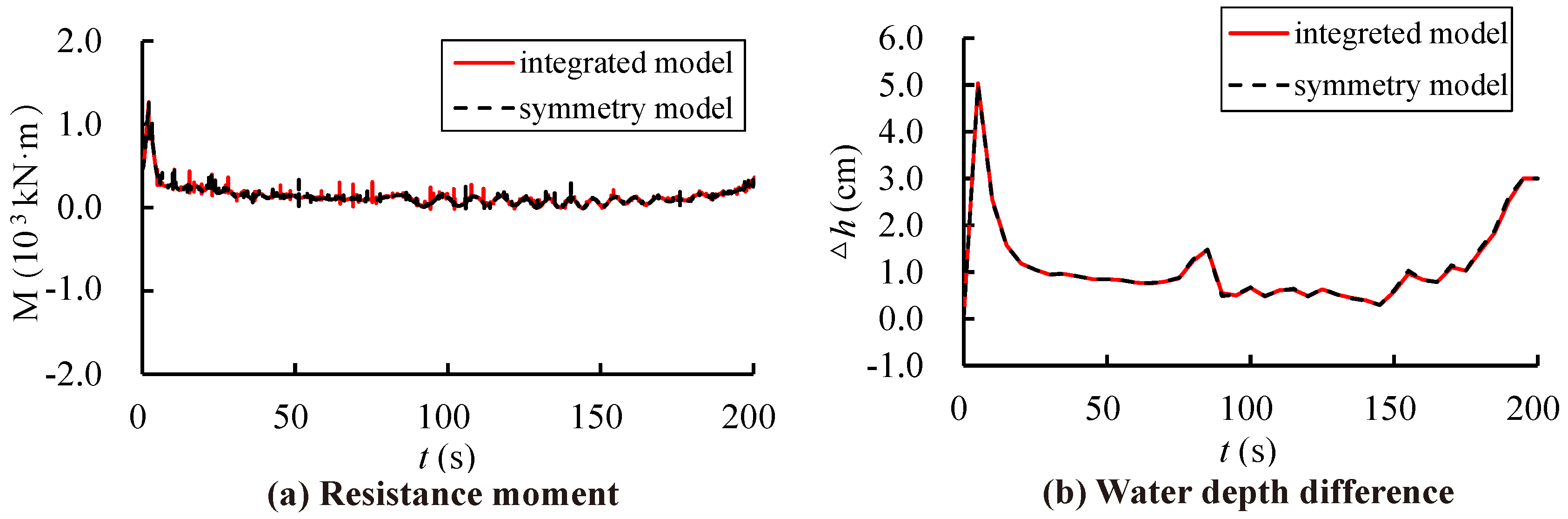
To economize the computer resources, half of the model, which only contains the left side of the ship lock, is established; seen in
Figure 10. The symmetry boundary is adopted for the vertical plane where the center line lies. The variation of submergence depth and its corresponding dynamic resistance moment in the integrated model are compared with the ones in
Figure 10 during the opening process. In the comparison conditions, the submergence depth in and out of the lock chamber both are both 9.8 m and the opening time of the miter gate is 200 s. The comparison results are shown in
Figure 11. It shows that although the lower approach channel is not in the symmetry boundary strictly, there is little effect on the hydrodynamic characteristics near the miter gate. Therefore, the model in
Figure 10 is used to study the hydrodynamic characteristics of the miter gate with different submergence depths and reverse heads.


