Abstract
In the literature, there are different criteria to represent the formation of a leader channel in short and long gap discharges. Due to the complexity of the physics of the heating phenomena, and the limitations of the computational resources, a simplified criterion for the minimum amount of electrical charge required to incept an unstable leader has recently been used for modeling long gap discharges and lightning attachments. The criterion is based on the assumption that the total energy of the streamer is used to heat up the gas, among other principles. However, from a physics point of view, energy can also be transferred to other molecular processes, such as rotation, translation, and vibrational excitation. In this paper, the leader inception mechanism was studied based on fundamental particle physics and the energy balance of the gas media. The heating process of the plasma is evaluated with a detailed two-dimensional self-consistent model. The model is able to represent the streamer propagation, dark period, and unsuccessful leaders that may occur prior to the heating of the channel. The main processes that participate in heating the gas are identified within the model, indicating that impact ionization and detachment are the leading sources of energy injection, and that recombination is responsible for loss of electrons and limiting the energy. The model was applied to a well-known experiment for long air gaps under positive switching impulses reported in the literature, and used to validate models for lightning attachments and long gap discharges. Results indicate that the streamer–leader transition depends on the amount of energy transferred to the heating process. The minimum electric charge required for leader inception varies with the gap geometry, the background electric field, the reduction of electric field due to the space charge, the energy expended on the vibrational relation, and the environmental conditions, among others.
1. Introduction
The transition from streamer to leader is characterized by an increase in the temperature of the gas and the formation of a plasma channel of high conductivity. The gas temperature of the streamers corresponds to the ambient temperature, ca. 300 K. Once streamers are incepted, and depending on the local electric field conditions, mechanisms such as electron impact and associative ionization, among others, take place. Such mechanisms generate thermal instability of the air, forming a heated plasma channel. The source of the current for heating the plasma is the electrical charge from streamer discharges. During streamer propagation, the electrons flow through the streamer channel into the high-voltage electrode and the positive and negative ions are left behind in the gap. The charge injected in the transition region supplies the energy to increase the gas temperature until the streamer propagation stops. Then, the relaxation of the vibrational temperature is evaluated and one part of the energy is used in the vibrational processes, while the other is transferred to the heating process. Once the temperature has been raised above a minimum threshold, ca. 1500 K, a leader channel can be considered as incepted.
In the extant literature, different models or criteria can be found to describe the streamer-to-leader transition. Some are engineering models based on laboratory results [1,2,3,4,5,6], some are based on particle electrical discharge physics [7,8,9,10,11,12], and others are simplifications of the numerical particle models [5,13,14]. However, due to the complexity of the physics, the computational time and resources required to perform detailed particle physics calculations, the majority of available models based on particle physics are applicable only to short gaps [9,11,15,16,17].
Recently, long gap breakdown and lightning attachment models have used a simplified criterion that requires a minimum charge of 1 μC for unstable leader inception [13,14,18,19,20,21]. Such criterion is based on the thermodynamic mechanism proposed by Gallimberti [7], which takes into account that temperature increases due to the Joule effect, the leader channel expansion, and the detachment process on negative ions, and assumes that all energy is directly transferred into heating, neglecting the transfer of energy into electronic, rotational, and translational excitation and vibrational relaxation.
The model described in this manuscript is based on previous models presented by the authors in [22,23,24,25] and features new elements such as particle density formation and gas heating equations, while also considering air composed of 14 species and more than 26 kinetic reactions. The model is intended for analyzing the main mechanisms responsible for the heating of plasma in electric fields that are inherent in the initiation of a leader discharge. It considers the kinetics of particles and the energy balance of the gas to evaluate the heating process for the formation of the leader channel in long air gaps. The self-consistent model calculates the heating of a plasma channel during the streamer-to-leader transition in a positive leader discharge. It is capable of representing the streamer, dark period, and unsuccessful positive leaders that may occur before the inception of the leader channel. The model is validated with experimental testing reported in [7]. The role of energy transfer, and the main mechanisms of the discharge are identified and discussed. Furthermore, the model is used to calculate the minimum charge required to incept an unstable leader in a typical high-voltage test configuration, and the obtained results are compared with the minimum charge criterion of 1 μC for unstable leader inception used in modelling long spark gaps and lightning attachments.
2. Model Formulation
The model solves the kinetic equations and dynamics of air heating considering the dominant mechanisms of electron generation and loss in the positive leader channel for long air gaps. It takes into account the reaction rates on the vibrational temperature of N2 molecules in the dynamics of the gas heating. The model covers gas temperatures ranging from 300 K to 1500 K.
In the calculations, it is assumed that all particle densities propagate in air as the main gas medium. The initial conditions of air are a non-perturbed atmosphere composed of 79% N2 and 21% O2 at ambient temperature. In total, 14 species (N2, N2(A3Σu+), O2, N2+, N2(B3Πg), N(2D), NO, O2+, O+, O, NO+, O−, N, O2−) and 26 reaction rates as functions of the gas temperature are considered. The reactions, excitation thresholds for electron impact, and electron drift velocity are listed in the Appendix.
The calculation starts with the evaluation of the background electric field, which depends on the voltage source and geometry of the arrangement. Then, the continuity equations of different particle densities are solved combined with Poisson’s equation. The electric current produced by the particle movement is calculated and the gas temperature is evaluated by means of the energy balance equations. If the gas temperature is equal or higher than 1500 K [7,9,26,27], then the streamer-to-leader transition occurs and a leader channel is considered as incepted. If the temperature does not surpass 1500 K, then the electric field is evaluated, again taking into account the background electric field and the effect of the densities of the charges on the electric field. Thereafter, the particle propagation and temperature change are calculated all over again. The particle density formation and propagation in the gas and the temperature of the gas depend on the local electric field conditions.
The calculation is performed assuming that a single streamer channel and its first streamer stem are formed directly after the current of the first streamer starts to flow. All phases of the streamer propagation are calculated by solving the continuity equations coupled with Poisson’s equation. In order to calculate the streamer propagation over long gaps for a long period of time, two-dimensional forms of the continuity equations have been used [28,29]. Streamers and the stem of the channel are assumed to occupy a narrow cylindrical channel. Assuming cylindrical symmetry of the streamer and stem, the problem is reduced to a two-dimensional, axisymmetric coordinate system. Figure 1 represents the discharge process of a positive discharge, highlighting the simulated region.
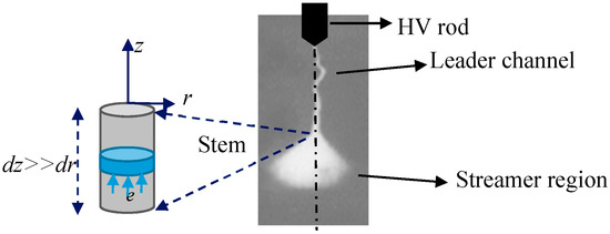
Figure 1.
Positive leader discharge with different parts of the discharge, such as the leader channel, the streamer region, and the stem. Notice that the simulated region for streamer-to-leader transition is highlighted and the symmetry axis is represented by a dashed line.
The calculation assumes initial conditions with an ambient gas temperature of 300 K and a density of electrons Ne with a Gaussian distribution located near the high-voltage electrode, while the rest of the simulation domain does not contain any free charges. The initial profile of the electron density in the streamer channel is selected as R0 = 0.001 m based on experimental measurements reported by Les Renardieres [30] and the peak density of electrons Ne0 is a fixed value of 2 × 1014 cm−3 as chosen in other studies [31]. The initial density of O2+ ions is equal to the electron density and the densities of all other ion species are equal to zero.
2.1. Continuity Equations of Particles
The continuity equations for electrons, ions, and active particles in Equations (2)–(5) describe the physical behavior of the particles to a step change in time, t. Ne is the particle density of electrons, and Np is the density of positive ions, Nn is the density of negative ions, and Nm is the density of active particles (electronically-excited particles, atoms, and NO molecules). The coefficients µe,p,n are the drift velocities of electrons, positive ions, and negative ions, respectively. The rate coefficients considered are the direct ionization α, stepwise ionization α′, associative ionization α″, dissociative electron attachment η, recombination β, electron detachment from negative ions in collisions with ground state molecules D, and active particles D*, loss of active particles Dq, and ambipolar diffusion coefficient Da. The rate coefficients are a function of the reduced electric field E/N. The superscript i in the equations denotes the ith excitation level of a molecule and also photons emitted from the level. The excitation coefficient of the level is δi, and τim is the lifetime of the excited molecule of the level. N and Na are the total density of all neutral species, N = 2.5 × 1019 cm−3, and the electronegative component density, respectively. Further descriptions of the rate coefficients and factors used in the model are summarized in the Appendix.
In this paper, photoionization is adopted as a secondary ionization process, and it is described with Equation (6), which includes the photon density Nph as a function of r, the speed of light c, the photon velocity c as a function of (c, θ, φ), and the photon’s absorption coefficient μ [32]:
The electric field E varies with the discharge current I induced by the motion of the electron density Ne as a function of r and its mobility μe, and the discharge cross-sectional area. The current on the stem is calculated using the following equation:
where the electric field E is the superposition of the background electric field produced by the voltage source and the electric field generated by the space charge variation in the gap. The electric field due to the voltage source is computed using the finite element method and the electric field due to the space charge is solved using Poisson’s equation and calculated using a successive over relaxation (SOR) method [33]. The electric field is solved in two dimensions. The continuity Equations (2)–(6) are solved simultaneously with Poisson’s equation. The algorithm uses a two-dimensional flux-corrected transport technique which allows for numerically solving the transport equations under strongly space charge dominated conditions such as those that occur at the head of a propagating streamer. It also includes the effects of non-uniform distribution of secondary electrons resulting from photoionization.
2.2. Gas Heating
The dynamics of the gas temperature is described by Equation (8), which considers the specific heat capacity of a gas as a constant volume, Cv, equivalent to 65 × 10−15 Vcm2, the thermal conductivity λ(T), and the total number of molecules in the gas N. The thermal conductivity of air is taken from [34]. The fast heating energy is evaluated in Equation (9), and is composed of the energy generated in the relaxation of electronic states WE, the fast heating reactions as the vibrational energy per unit length of N2 molecules Wv, the translational and vibrational temperature of neutral, Th and Tv, respectively, and the time of vibrational relaxation τvt.
The vibrational energy is described with Equation (10) and is related to the vibrational quantum of the N2 molecule = 0.29 eV [15] and k Boltzmann constant. The time of vibrational relaxation τvt reported by Gallimberti [7] is used. The vibrational relaxation rates are taken from experimental results for N2, O2, and air [16,31,35,36].
The continuity Equations (2)–(6) and transport Equation (8) were solved using the flux-corrected transport (FCT) technique with Zalesak’s peak preserver routine modifications, as described in [37,38]. The equations were solved in a non-uniform radial grid with the finest resolution of ∆r = R0/1000 m. The grid size increased radially following an exponential function. Chemistry source terms were also integrated in time with the second-order midpoint method under several restrictions for the time step ∆t in order to capture the evolution of all kinetic processes, e.g., ∆t << 1/α, 1/η.
3. Validation of the Model
The model was applied for validation to the conditions of the experiments reported in [7,30]. The test consisted of applying positive switching impulses to a rod-plane arrangement. The applied voltage had a maximum value of 2200 kV and a waveform with a rise and decay time of 500 and 10,000 μs, respectively. The gap distance between the highvoltage electrode and the plane was 10 m, and the high-voltage rod had a hyperboloid tip of 0.01 m in radius. The experimental test aimed to identify all stages of long gap discharges for rod electrodes with different tip termination. The results presented in this manuscript are focused on the main parts of the positive long gap discharge, such as streamer and leader formation after the first streamer inception.
3.1. Discharge Characteristics
Figure 2 presents the current characteristic calculated with the model, until the condition of heated plasma was fulfilled, i.e., the gas temperature reached 1500 K. The current increased and reduced several times until a continuous growth stage was attained. Similar behavior was reported by [7], where small current pulses were measured for high-voltage electrodes with a very small curvature radius, and many current pulses appeared before the continuous leader inception.
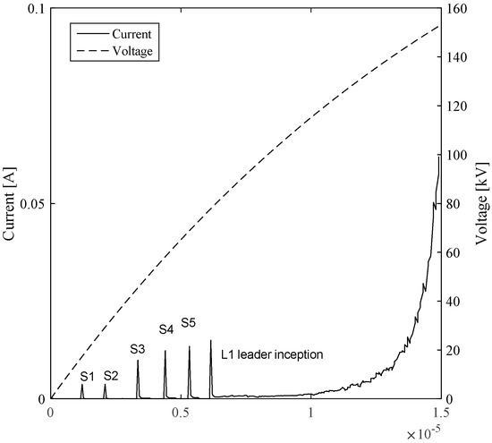
Figure 2.
The discharge current calculated with the model, until the temperature of 1500 K was achieved. The continuous line represents the current magnitude and the dashed line corresponds to the applied voltage. Notice that the current increased and decreased several times. The voltage level is at the rise time of the waveform.
Figure 2 includes the characteristics of the applied voltage. It was observed that the voltage continuously increased and its maximum magnitude was not achieved when the leader channel was already thermalized. As the voltage source was increasing in magnitude, subsequent current pulses were continuously incepted. However, the energy provided by the current pulses was not enough to thermalize the channel to a temperature in the order of 1500 K. During the leader inception process, the aborted pulses triggered the increase in temperature due to the injection of energy.
The peaks of the current characteristics labelled as S1, S2, S3, S4, and S5 can be explained as follows: the rise is due to the initial growth of electronic charges; densities of positive and negative ions are left in the gap and, meanwhile, the electrons propagate towards the high-voltage electrode. The ion propagation is very slow and, consequently, the local electric field is reduced and the current decreases. As the electric field due to the voltage source increases, the negative ions drift slowly. Eventually, the secondary ionization process, i.e., photoionization, takes place providing new electrons for the continuation of the process. The average velocity of propagation of the streamer obtained from the model is ca. 0.5 × 10⁶, which coincides with the calculations reported in [27,39].
Figure 3 illustrates the location of particle densities after the formation of the current pulse S2 at time, t = 2 × 10⁻⁶ s. The figure shows how in front of the high-voltage electrode, particles were distributed in the gap. The positive ions are located close to the high-voltage electrode. Meanwhile, negative ion and electron densities were in the first centimeters of the gap in front of the high-voltage electrode, towards the grounded plane. Figure 3 shows the level of detail the model allows to analyze the discharge process in the gap. Details of the reactions and processes that participate in the discharge are presented in the coming sections.
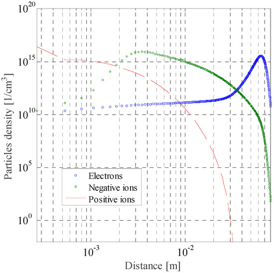
Figure 3.
Particle densities distribution in the air gap at time t = 2 × 10⁻⁶ s. The distance axis corresponds to distance from the high-voltage electrode towards the grounded plane.
3.2. Temperature Change—Leader Inception
The translational and vibrational temperatures integrated over the entire domain against time are presented in Figure 4. It can be seen that the vibrational temperature Tv increased during each current pulse due to efficient excitation of the vibrational states. The translational temperature Th was also increased, reaching its maximum value at the end of the current pulses because of fast heating produced by the energy injection of all subsequent current pulses. For this particular case, vibrational temperature Tv was always higher than the translational temperature Th, indicating a strong vibrational nonequilibrium during the streamer-to-leader transition.
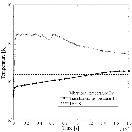
Figure 4.
Vibrational (Tv) and translational (Th) temperature of gas integrated over the entire domain until leader inception is reached. Notice that the dotted line indicates the limit of 1500 K which is defined as the temperature for a leader to be incepted.
The variation of translational temperature vs. time is in agreement with the discharge current characteristic presented in Figure 2. Initially, the translational temperature increased rapidly due to the fast electron generation, then the rate of the increment of temperature was reduced, but the translational temperature increased continuously until the thermalization of the channel occurred when the translational temperature increased above 1500 K. The leader inception or maximum temperature was achieved after 12 × 10−6 s and the total charge injected to incept a leader channel was 0.53 × 10⁻⁶ C. The results obtained with the model are in agreement with the measurements performed in [7].
Figure 5 and Figure 6 illustrate the main mechanisms and the particles that participate in the heating of the gas. Figure 5 shows the density evolution of O, N, and NO integrated over the entire domain in time for temperature variation from 300 K to 1500 K. It is observed that during this time the atoms were produced mainly via electron–impact dissociation. The formation of NO increased in the initial stage, and the NO molecules accelerated the electron–impact ionization because of their low ionization energy. O atoms increased as well during the heating process, indicating a fast electron detachment from negative ions.
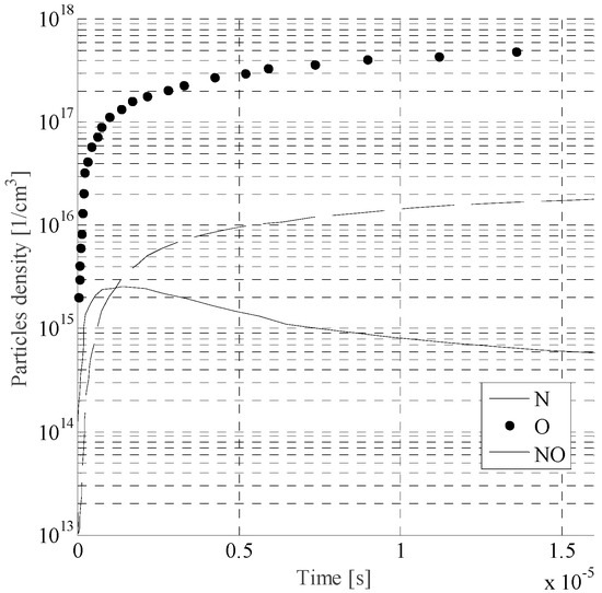
Figure 5.
Densities of N, O, and NO vs. time during the change of temperature from 300 K to 1500 K.
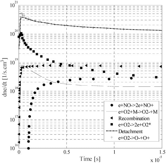
Figure 6.
Time evolution of rates of electron production and loss through different mechanisms during the change of temperature from 300 K to 1500 K.
Figure 6 identifies the leading processes on the production and loss of electrons in the gas over the entire domain. Recombination, detachment, ion dissociation, and attachment are included in the figure. The principal process to contribute in the temperature increment and the inception of the leader was detachment. During the change of temperature, the recombination mechanism also occurred; it initially increased, but after a few microseconds reached steady-state behavior. The recombination process was the primary process that limited the energy input into the leader channel, i.e., it was the principal mechanism of electron loss in air.
4. Role of the Vibrational Energy and Relation to Minimum Charge Required for Leader Inception
To analyze the effect of the vibrational energy on the heating of the channel, calculations of leader inception for the different radii of the tip of the high-voltage electrode were performed. Three different radii were compared: hemispherical, with a 0.30 m radius; hyperboloid, 0.10 m; and cone, 0.01 m. Other characteristics of the test, such as the applied voltage magnitude, waveform, and gap distance, among others, were kept as described in Section 3. Table 1 summarizes the fraction of energy expended on the vibrational process for different tip shapes.

Table 1.
Vibrational energy fraction on the streamer–leader transition for different tip shapes of the high-voltage rod.
Results indicate that the vibrational energy is influenced by the geometry of the arrangement. For small-curvature electrodes, more energy is expended on vibrational processes, and for large-radius electrodes the energy used on vibrational energy is smaller. Experimental results revealed that the fraction of energy invested on translational and rotational energy depends on the electric field magnitude [35,40]. The electric field magnitude depends on the background electric field and the electric field reduction generated by the space charge.
The energy invested in vibrational processes affects the time required for heating the gas to the critical value of 1500 K. Figure 7 shows the effect of the vibrational energy on the translational temperature increment of the gas. The translational temperature of 1500 K was reached at different times for the different tip of the high-voltage electrode.
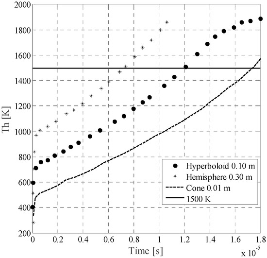
Figure 7.
Translational temperature Th before and until leader inception is achieved for a rod–plane 10 m gap arrangement with different high-voltage tip electrode radii. Notice that the figure is the result of integration over the entire domain.
Charge Required to Leader Inception
To be able to determine the applicability of the simplified criteria of 1 μC for unstable leader inception used on lightning attachment and long air gap discharge calculation, the electric charge required to reach 1500 K for each tip radius of the high-voltage electrode was calculated and summarized in Table 2.

Table 2.
Total charge injected on the streamer–leader transition for different tip radii.
The results indicate that sharper tips, rather than blunt ones, allow more charge to flow in the channel before thermalization takes place. The charge calculation shows that the injected charge for the inception of the leader varies with the vibrational energy, which changes with the background electric field, the reduced electric field produced by the space charge, and the environmental conditions. Therefore, to assume a constant value of charge of 1 μC independently of the geometry of the arrangement, the environmental conditions, the background electric field, among others, may lead to incorrect estimations of the leader inception and may disregard part of the physics of the discharge. Similar results have been reported in [41], where it was experimentally observed that the charge required for the transition from streamer to leader changes with the gap distance between the high-voltage electrode and the ground plane, i.e., the electric field conditions of the arrangement.
5. Conclusions
A self-consistent model based on continuity equations of particles and energy balance of the gas was presented to evaluate the heating process for the formation of a leader channel in long air gaps. The model takes into account the influence of the electric field and gas temperatures in the range of 300–1500 K. The model is capable of representing the streamer propagation, dark period, and unsuccessful positive leaders that may occur before the thermalization of the leader channel.
The calculation can provide a detailed description of the electron and ion densities as functions of time and position. The detail of the calculation extends from the initial streamer development within a resolution of tenths of nanoseconds to leader inception at tenths of microseconds. The results were obtained by solving two-dimensional particle continuity equations and a two-dimensional solution of Poisson’s equation.
Numerical simulations of the model in a long air gap rod to plane electrode arrangement indicate that:
- Photoionization is essential for the development and propagation of positive streamers. It enables the seed electrons in the high electric field region at the head of the streamer.
- The most important mechanisms to increase the electron density, and consequently incept a leader, were the fast electron detachment from negative ions caused by oxygen atoms and the acceleration of the electron impact ionization due to NO molecules. These processes lead to an increase of electron density and a decrease of the local electric field.
- The rise of temperature on the channel directly depended on the energy available at the streamer channel, the electric field reduction and the vibrational energy relaxation, and the recombination of particles, which were the principal processes to limit the energy input into the leader. Consequently, it is incorrect to assume that all streamer energy is directly used for heating and a unique amount of charge is required to heat the channel and incept a leader.
- Calculations indicate that sharp tips allow more charge to flow into the channel before leader inception takes place than blunt tips. Therefore, the amount of electrical charge required to achieve leader inception conditions varies and depends on the electric field distribution of the arrangement, i.e., geometry, applied voltage, the space charge, and environmental conditions, among others.
- The study shows that the criterion of a constant minimum electrical charge of 1 μC to incept a leader channel, used in lightning attachment and long gap discharge models, is not well-founded and it disregards part of the physics of the discharge. Leader inception depends on the amount of energy injected into the channel used for heating processes.
Author Contributions
The study was completed with cooperation between the authors. Liliana Arevalo, as first author, prepared the models, performed the calculations and wrote the manuscript. Vernon Cooray contributed to the discussion of the theory.
Conflicts of Interest
The authors declare no conflict of interest.
Appendix A

Table A1.
List of chemical reactions taken from [12,31,42].
Table A1.
List of chemical reactions taken from [12,31,42].
| Reaction | Rate Coefficient (cm3/s or cm6/s) | |
|---|---|---|
| Ionization | ||
| Direct ionization α | ||
| (A1) | 4.9 × 10⁻⁹ exp (–657/(E/N))F | |
| (A2) | 8.1 × 10⁻⁹ exp (–925/(E/N))F | |
| Stepwise ionization α′ | ||
| (A3) | 5.0 × 10⁻⁹ exp (–460/(E/N))F | |
| (A4) | 4.0 × 10⁻⁹ exp (–713/(E/N))F | |
| Associative ionization α″ | ||
| (A5) | 1.9 × 10⁻⁹ | |
| (A6) | 1.4 × 10⁻¹⁰ | |
| (A7) | 2.6 × 10⁻¹⁷ T1.43 exp (–31140/T) | |
| Electron-ion recombination β | ||
| (A8) | 2.0 × 10⁻⁷ (300/Te)0.7 | |
| (A9) | 2.8 × 10⁻⁷ (300/Te)0.5 | |
| (A10) | 2.3 × 10⁻⁶ Te–0.45 | |
| Electron attachment η | ||
| (A11) | ||
| Electron detachment D and D* | ||
| (A12) | 5 × 10⁻¹⁰ | |
| (A13) | ||
| Electron impact dissociation | ||
| (A14) | k(E/N)F | |
| (A15) | 4.4 × 10⁻¹¹ k(E/N)F | |
| (A16) | 6.4 × 10⁻¹⁰ | |
| Electron impact excitation | ||
| (A17) | 1.1 × 10⁻¹⁰ | |
| (A18) | 3.6 × 10⁻¹⁰ | |
| Chemical reactions | ||
| (A19) | 2.54 × 10⁻¹² | |
| (A20) | 3.0 × 10⁻¹⁰ | |
| (A21) | 2.1 × 10⁻¹¹ | |
| (A22) | 7.0 × 10⁻¹² | |
| (A23) | 10−12T−0.5 | |
| (A24) | ||
| (A25) | ||
| (A26) | ||

Table A2.
Excitation threshold for electron impact ionization, excitation, and dissociation [44].
Table A2.
Excitation threshold for electron impact ionization, excitation, and dissociation [44].
| Reaction | εj* [eV] | |
|---|---|---|
| (A27) | 12.08 | |
| (A28) | 15.58 | |
| (A29) | 9.26 | |
| (A30) | 13.62 | |
| (A31) | 6.17 | |
| (A32) | 7.35 | |
| (A33) | 5.9 |
The electron drift velocity was taken from [39]:
The negative ion drift velocity was taken from [44]:
The positive ion drift velocity was taken from [44]:
The ambipolar diffusion coefficient is given by:
where kB is the Boltzmann constant and qe is the electronic charge.
References
- Baldo, G.; Gallimberti, I.; Garcia, H.N.; Hutzler, B.; Jouaire, J.; Simon, M.F. Breakdown phenomena of long gaps under switching impulse conditions influence of distance and voltage level. IEEE Trans. Power Appar. Syst. 1975, 94, 1131–1140. [Google Scholar] [CrossRef]
- Jones, B. Switching Surges and Air Insulation. Philos. Trans. R. Soc. Lond. Ser. A Math. Phys. Sci. 1973, 275, 165–180. [Google Scholar] [CrossRef]
- Carrara, G.; Thione, L. Switching surge strength of large air gaps: A physical approach. IEEE Trans. Power Appar. Syst. 1976, 95, 512–524. [Google Scholar] [CrossRef]
- Rizk, F.A.M. Switehing impulse strength of air insulation: Leader inception criterion. IEEE Power Eng. Rev. 1989, 9, 60–61. [Google Scholar] [CrossRef]
- Goelian, N.; Lalande, P.; Bacchiega, G.L.; Gazzani, A.; Gallimberti, I. A simplified model for the simulation of positive-spark development in long air gaps. Appl. Phys. 1997, 30, 2441–2452. [Google Scholar] [CrossRef]
- Hutzler, B.; Hutzler-Barre, D. Leader Propagation Model for Predetermination of Switching Surge Flashover Voltage of Large Air Gaps. IEEE Trans. Power Appar. Syst. 1978, PAS-97, 1087–1096. [Google Scholar] [CrossRef]
- Gallimberti, I. The mechanism of the long spark formation. J. Phys. Colloq. 1979, 40, 193–250. [Google Scholar] [CrossRef]
- Vidal, F.; Gallimberti, I.; Rizk, F.A.M.; Johnston, T.W.; Bondiou-Clergerie, A.; Comtois, D.; Kieffer, J.C.; La Fontaine, B.; Mercure, H.P.; Pépin, H. Modeling of the air plasma near the tip of the positive leader. IEEE Trans. Plasma Sci. 2002, 30, 1339–1349. [Google Scholar] [CrossRef]
- Popov, N.A. Formation and development of a leader channel in air. Plasma Phys. Rep. 2003, 29, 695–708. [Google Scholar] [CrossRef]
- Bazelyan, E.M.; Yu, P.R.; Aleksandrov, N.L. The effect of reduced air density on streamer-to-leader transition and on properties of long positive leader. J. Phys. D Appl. Phys. 2007, 40, 4133. [Google Scholar] [CrossRef]
- Marode, E.; Bastien, F.; Bakker, M. A model of the streamer-induced spark formation based on neutral dynamics. J. Appl. Phys. 1979, 50, 140–146. [Google Scholar] [CrossRef]
- Aleksandrov, N.L.; Bazelyan, E.M.; Raizer, Y.P. Initiation and development of first lightning leader : The effects of coronae and position of lightning origin. Atmos. Res. 2005, 76, 307–329. [Google Scholar] [CrossRef]
- Bondiou, A.; Gallimberti, I. Theoretical modelling of the development of the positive spark in long gaps. J. Phys. D Appl. Phys. 1994, 27, 1252–1266. [Google Scholar] [CrossRef]
- Beccerra, M.; Cooray, V. A simplified physical model to determine the lightning upward connecting leader inception. IEEE Trans. Power Deliv. 2006, 21, 897–908. [Google Scholar] [CrossRef]
- Naidis, G.V. Dynamics of streamer breakdown of short non-uniform air gaps. J. Phys. D Appl. Phys. 2005, 38, 3889–3893. [Google Scholar] [CrossRef]
- Naidis, G.V. Simulation of streamer-to-spark transition in short non-uniform air gaps. J. Phys. D Appl. Phys. 1999, 32, 2649–2654. [Google Scholar] [CrossRef]
- Popov, N.A. Study of the formation and propagation of a leader channel in air. Plasma Phys. Rep. 2009, 35, 785–793. [Google Scholar] [CrossRef]
- Lalande, P.; Bondiou-Clergerie, A.; Bacchiega, G.; Gallimberti, I. Observations and modeling of lightning leaders. Comptes Rendus Phys. 2002, 3, 1375–1392. [Google Scholar] [CrossRef]
- Arevalo, L.; Wu, D.; Jacobson, B. A consistent approach to estimate the breakdown voltage of high voltage electrodes under positive switching impulses. J. Appl. Phys. 2013, 114, 83301. [Google Scholar] [CrossRef]
- Arevalo, L. Numerical Simulations of Long Spark and Lightning Attachment; Uppsala University: Uppsala, Sweden, 2011. [Google Scholar]
- Becerra, M.; Cooray, V.; Hartono, Z.A. Identification of lightning vulnerability points on complex grounded structures. J. Electrost. 2007, 65, 562–570. [Google Scholar] [CrossRef]
- Arevalo, L.; Cooray, V. Streamer to leader transition criteria for propagation of long sparks and lightning leaders. In Proceedings of the 2014 International Conference on Lightning Protection (ICLP), Shanghai, China, 11–18 October 2014; Institute of Electrical and Electronics Engineers Inc.: Piscataway, NJ, USA, 2014; pp. 480–483. [Google Scholar]
- Arevalo, L.; Cooray, V. Upward leader inception caused by a sudden change of cloud electric field. In Proceedings of the 2014 International Conference on Lightning Protection (ICLP), Shanghai, China, 11–18 October 2014; Institute of Electrical and Electronics Engineers Inc.: Piscataway, NJ, USA, 2014; pp. 484–487. [Google Scholar]
- Arevalo, L.; Cooray, V. Corona charge produced by thundercloud fields in grounded rods. In Proceedings of the 2012 International Conference on Lightning Protection (ICLP), Vienna, Austria, 2–7 September 2012; pp. 1–6. [Google Scholar]
- Arévalo, L.; Becerra, M.; Román, F. Positive corona current simulation in a non-uniform coaxial arrangement. WSEAS Trans. Inf. Sci. Appl. 2005, 2, 1595–1606. [Google Scholar]
- Bazelyan, É.M.; Raizer, Y.P. Spark Discharge; CRC Press: Boca Raton, FL, USA, 1997; ISBN 9780849328688. [Google Scholar]
- Aleksandrov, N.; Bazyelan, E.; Kochetov, I.; Dyatko, N. The ionization kinetics and electric field in the leader channel in long air gaps. J. Phys. D Appl. Phys. 1997, 30, 1616–1624. [Google Scholar] [CrossRef]
- Dhali, S.K.; Williams, P.F. Two-dimensional studies of streamers in gases. J. Appl. Phys. 1987, 62, 4696–4707. [Google Scholar] [CrossRef]
- Luque, A.; Ratushnaya, V.; Ebert, U. Positive and negative streamers in ambient air: Modelling evolution and velocities. J. Phys. D Appl. Phys. 2008, 41, 234005. [Google Scholar] [CrossRef]
- Group, L.R. Research on long gap discharges at Les Renardières. Electra 1972, 23, 53–157. [Google Scholar]
- Popov, N.A. Investigation of the mechanism for rapid heating of nitrogen and air in gas discharges. Plasma Phys. Rep. 2001, 27, 886–896. [Google Scholar] [CrossRef]
- Legler, W. Anregung von UV-Strahlung in Stickstoff und Wasserstoff durch einen Elektronenschwarm. Z. Phys. 1963, 173, 169–183. [Google Scholar] [CrossRef]
- Davies, A.J.; Evans, C.J.; Townsend, P.; Woodison, P.M. Computation of axial and radial development of discharges between plane parallel electrodes. Proc. Inst. Electr. Eng. 1977, 124, 179. [Google Scholar] [CrossRef]
- Dresvin, S.; Donskoi, A. Physics and Technology of Low-Temperature Plasmas; Iowa State University Press: Ames, IA, USA, 1977; ISBN 0813819504. [Google Scholar]
- Popov, N.A. Fast gas heating in a nitrogen—Oxygen discharge plasma: I. Kinetic mechanism. J. Phys. D Appl. Phys. 2011, 44, 285201. [Google Scholar] [CrossRef]
- Flitti, A.; Pancheshnyi, S.V. Gas heating in fast pulsed discharges in N–O mixtures. Eur. Phys. J. Appl. Phys. 2009, 45, 21001. [Google Scholar] [CrossRef]
- Kennedy, J.T. Study of the Avalanche to Streamer Transition in Insulating Gases; Eindhoven University of Technology: Eindhoven, The Netherlands, 1995. [Google Scholar]
- Steven, Z. Fully dimensional fluz corrected transport algorithms for fluids. J. Comput. 1979, 31, 335–362. [Google Scholar]
- Morrow, R.; Lowke, J.J. Streamer propagation in air. J. Phys. D Appl. Phys. 1999, 30, 614–627. [Google Scholar] [CrossRef]
- Bastien, F.; Marode, E. Breakdown simulation of electronegative gases in non-uniform field. J. Phys. D Appl. Phys. 1985, 18, 377–393. [Google Scholar] [CrossRef]
- Wu, C.; Xie, S.; Qi, F.; Li, B.; Wan, J.; He, J. Effect of corona discharges on the inception of positive upward leader-streamer system. Int. J. Mod. Phys. B 2013, 27, 1350165. [Google Scholar] [CrossRef]
- Kossyi, I.A.; Kostinsky, A.Y.; Matveyev, A.A.; Silakov, V.P. Kinetic scheme of the non-equilibrium discharge in nitrogen-oxygen mixtures. Plasma Sources Sci. Technol. 1992, 1, 207–220. [Google Scholar] [CrossRef]
- Benilov, M.S.; Naidis, G.V. Modelling of low-current discharges in atmospheric-pressure air taking account of non-equilibrium effects. J. Phys. D Appl. Phys. 2003, 36, 1834–1841. [Google Scholar] [CrossRef]
- Capitelli, M.; Ferreira, C.M.; Gordiets, B.F.; Osipov, A.I. Plasma Kinetics in Atmospheric Gases; Springer: New York, NY, USA, 2000; ISBN 978-3-662-04158-1. [Google Scholar]
© 2017 by the authors. Licensee MDPI, Basel, Switzerland. This article is an open access article distributed under the terms and conditions of the Creative Commons Attribution (CC BY) license (http://creativecommons.org/licenses/by/4.0/).