Article

Optimization of Ventilation Systems in Large Welding Workshops with Multiple Dust Sources: A Case Study of a 300-m-Long Welding Workshop

1
China Academy of Safety Science and Technology, Beijing 100012, China
2
NHC Key Laboratory for Engineering Control of Dust Hazard, Beijing 100012, China
3
School of Resources and Safety Engineering, University of Science and Technology Beijing, Beijing 100083, China
4
Aerospace HIWING Security Technology Engineering Co., Ltd., Beijing 100074, China
5
Division of Health Risk Factors Monitoring and Control, Shanghai Municipal Center for Disease Control and Prevention, Shanghai 201107, China
6
School of Resources and Environmental Engineering, Nanchang University, Nanchang 330031, China
*
Author to whom correspondence should be addressed.
Atmosphere 2026, 17(9), 843; https://doi.org/10.3390/atmos17090843 (registering DOI)
Submission received: 25 June 2026 / Revised: 23 August 2026 / Accepted: 26 August 2026 / Published: 28 August 2026
(This article belongs to the Special Issue Improvement of Air Pollution Control Technology)

Abstract

Welding technology, extensively utilized in modern industry, poses significant health risks due to metal dust exposure, which can lead to respiratory discomfort, neurological issues, and an increased risk of lung cancer and pneumoconiosis. Enhancing ventilation within factory buildings has proven to be an economical approach to mitigating these risks. This study employs computational fluid dynamics (CFD) to model the airflow and dust transport within a large welding workshop measuring 300 m in length, 28 m in width, and 21 m in height. The impact of the exhaust-to-supply air ratio (ESR) and the height of the side exhaust port (SEP) on dust removal efficiency is investigated. Comparative analysis of transport dynamics between low-density aluminum alloy welding fume and high-density carbon steel welding fume reveals optimal dust exhaust designs. The study identifies two peaks in workshop air velocity at 0–2 m and 8–12 m above the ground, with the top exhaust port (TEP) outperforming the SEP in dust removal. An increased ESR accelerates the upward migration of welding fume, reducing lateral dispersion. An improperly set SEP height can lead to airflow short-circuiting or excessive lateral dispersion, hindering effective dust removal. Optimal SEP height for aluminum alloy and carbon steel dust are determined to be 5 m and 6 m, respectively.

1. Introduction

Modern welding technology, widely regarded for its reliability, flexibility, and cost-effectiveness, is extensively utilized across the construction, energy, aerospace, and shipbuilding sectors, driving the rapid advancement of industrial development. However, the inherent characteristics of welding processes result in the emission of toxic and harmful gases, as well as dust particles, with the latter primarily posing a risk in the form of welding fume within the workshop environment [1]. Prolonged exposure to high concentrations of welding fume can impair respiratory and pulmonary function, manifesting as chronic coughing, chest tightness, and pneumoconiosis, while also posing neurological risks due to toxic metal components such as manganese. More critically, quantitative risk assessments indicate that the carcinogenic risk from fine particulates and metallic elements in welding fume frequently exceeds acceptable thresholds, significantly elevating the lifetime probability of lung cancer among long-term welders, with dust concentration and exposure duration identified as the primary determinants of such health risks [2,3,4,5].
Ventilation technology stands as the primary method for dust control in large-scale welding workshops, complementing the enhancement of welding process automation [6]. It represents a cost-effective solution, often the first choice when aiming to improve the quality of the working environment. The optimization of ventilation systems to reduce energy consumption is a widely researched topic. Dahal et al. [7] employed CFD to investigate ventilation control strategies for welding fume. They found that conventional manual measurement methods for assessing fume dispersion are operationally complex and prone to errors. To address this, they proposed an indirect prediction approach that estimates fume distribution by predicting CO2 concentration, achieving a correlation coefficient of 0.74. Yen et al. [8] examined the physicochemical properties and health risks of PM from welding and grinding in a mechanical workshop. The highest PM concentrations occurred within 0.5 m of welding operations, with PM2.5 and PM10 reaching 1716 and 3024 μg/m3 when using ilmenite electrodes. Cd and Cr(VI) presented the highest carcinogenic risks in pickling and painting sections, while Mn showed elevated non-carcinogenic risk across all sections. Frey et al. [9] investigated particle characteristics in metal vapor plumes during laser beam welding under atmospheric and vacuum conditions. The particle number increased with decreasing pressure: at 10 mbar, particles formed a bcc solid solution of Cr, Cu, Fe, Mn, and Ni, while at 1000 mbar, complex spinel-type phases such as NiCr2O4 and NiFe2O4 appeared. SEM and TEM analyses revealed distinct morphologies and structures at different pressures, with oxygen content significantly influencing particle formation and composition. Rahul et al. [10] developed a novel SMAW electrode for stainless steel by coating the core wire with nano-zirconia and adding nanoparticles to the flux coating, achieving an 82% reduction in fume generation rate and an 85% decrease in respirable zone concentration compared to conventional electrodes. At a dosage of 100 g/mL, the new electrode reduced total Cr(VI) by 68%, with 36% and 52% reductions in the inhalable and respirable fractions, respectively. The improved deposition efficiency further indicates that nanoparticle addition not only suppresses fume and toxic emissions but also enhances welding productivity.
Computational fluid dynamics (CFD) is widely used in the optimization of ventilation and dust removal in buildings with large computational space such as welding workshops, where it is difficult to carry out field tests [11,12,13]. Gao et al. [14] demonstrated that increasing the height difference between air inlets and outlets can enhance ventilation efficiency, as modeled through CFD. When the distance between the air inlet and the air outlet increases from 15.8 m to 19.8 m, the average temperature decreases by 1 K in the horizontal direction and 3 K in the vertical direction of the workshop. Dong et al. [15] found that the average dust concentration was 1.72 mg/m3 under natural ventilation, 0.53 mg/m3 under mechanical ventilation, and 0.31 mg/m3 under mixed ventilation. Gao et al. [16] reported that induction fans, when integrated into traditional displacement ventilation, can achieve dust removal rates exceeding 50% to 75% in high-welding workshops. Wang et al. [17] optimized the exhaust hood structure in welding workshops through CFD modeling, achieving a collection efficiency of up to 93.75% under certain conditions. When the exhaust hood tuyere speed was set to 4.80 m/s and the dimensionless ratio (the ratio of baffle length to exhaust hood suction diameter) was greater than 0.54, the exhaust hood collection efficiency could reach 93.75%. Jiang et al. [18] established a mathematical model for dust diffusion based on Fick’s first law of diffusion, validating its reliability through a combination of Fluent modeling and actual detection data, thus providing a reference for predicting dust distribution patterns in industrial settings.
Despite these valuable contributions, several critical research gaps remain unaddressed. Most existing studies focus on small- to medium-sized workshops or single welding stations, while large-scale welding workshops—exceeding 200 m in length—have received very limited attention. The airflow and dust transport dynamics in such expansive spaces are fundamentally different from those in smaller enclosures due to longer transport distances, stronger thermal stratification, and more complex multi-source interactions. The influence of dust material density on ventilation efficiency has rarely been systematically investigated, even though workshops commonly process different metals (e.g., carbon steel and aluminum alloy) that generate dust with distinctly different physical properties. Although side exhaust ports (SEPs) are widely used in industrial ventilation, the effect of SEP height on dust removal performance in large-span workshops has not been quantitatively optimized, and its interaction with the exhaust-to-supply air ratio (ESR) remains poorly understood.
To bridge these gaps, this study contributes to the field by targeting an exceptionally large welding workshop and investigating the coupled effects of ESR and SEP height on dust removal efficiency for two distinct dust types. The specific objectives of this study are: (1) to characterize the vertical air velocity distribution and dust concentration profiles in the workshop under varying ESR conditions; (2) to evaluate the influence of SEP height (ranging from 3 to 8 m) on dust removal performance for both carbon steel and aluminum alloy welding fume; and (3) to determine the optimal SEP height for each dust type and provide actionable design recommendations. The findings are expected to offer practical guidance for engineers and facility managers seeking cost-effective ventilation optimization strategies without undertaking costly system overhauls.

2. Materials and Methods

2.1. Materials

The welding workshop is a cuboid space measuring 300 × 28 × 21 m. At the time of the study, five welding stations were in operation, and no effective ventilation system had been installed. This study provides a reference for the design and implementation of a ventilation system for this workshop. Carbon steel, one of the welding materials, is an iron–carbon alloy with a carbon content ranging from 0.022% to 2.11%. Aluminum alloy, another welding material, typically incorporates alloying elements such as copper, zinc, manganese, silicon, and magnesium. Its density is low, but the strength is relatively high, comparable to or exceeding that of high-quality steel, offering good plasticity and the ability to be processed into various profiles. It is widely used in industry and is second only to steel in terms of usage quantity. The welding fumes from carbon steel and aluminum alloy were sampled and analyzed. The true density of carbon steel welding fume is 3.84 g/cm3, while that of aluminum alloy welding fume is 2.25 g/cm3.
It is found that carbon steel welding fume predominantly consists of equiaxed particles, mainly composed of some large spherical particles and fine particle agglomerations. While aluminum alloy welding fume includes single spherical particles, chain structures, and network structures formed by spherical particles, most of which exist in the form of multi-particle agglomerates.
The particle size distribution of carbon steel and aluminum alloy welding fume was determined by a laser particle size distribution instrument (Bettersize2600 Type, Dandong Baite Technology Co., Ltd., Dandong, China). The median diameter of carbon steel welding fume is 3.1 μm. The particle size of carbon steel welding fume presents a normal distribution, and the particle size range with the largest proportion is 2.1~2.3 μm. The median particle diameter of aluminum alloy welding fume is 4.7 μm, with a positively skewed normal distribution and the largest particle size range of 1.8~2.1 μm.
The proportion of PM2.5 and PM10 in carbon steel welding fume is higher than that of aluminum alloy welding fume, which are difficult to settle and more harmful to the human body and environment. From the observation and analysis of the micro-morphology of welding fumes, it can be observed that the majority of aluminum alloy dust forms flocculent agglomerates, resulting in larger particle sizes.

2.2. Methods

2.2.1. Theoretical Analysis

Large Eddy Simulation (LES) offers high-resolution transient flow prediction but is computationally prohibitive for full-scale long-duration simulations. Detached Eddy Simulation (DES) improves near-wall accuracy over RANS but requires complex meshing and remains computationally intensive. The Lattice Boltzmann Method (LBM) handles complex geometries well with parallel computing advantages, yet lacks sufficient validation for thermal buoyancy-driven particle-laden flows. Considering the requirements of large-scale geometry, thermal buoyancy, particle tracking, and long-duration simulation in this study, the RANS k-ε model combined with the discrete phase model (DPM) achieves the most practical balance between accuracy and computational cost, and has been well-validated in similar industrial ventilation studies—therefore, it was adopted as the fundamental modeling approach.
The dust volume fraction in the workshop is relatively low, less than 10%, so the discrete phase model can be used to analyze particle movement [19]. In the Euler coordinate system, the discrete phase model integrates the differential equation of particle force through time and solves the random orbit of particles (droplets or bubbles). The particle phase equation is:
d v p i d t = 18 μ g ρ p d p 2 C s Re 24 v g i v p i + g i 1 ρ g ρ p + F x i
where vpi is the particle velocity component in the direction i (i = x, y, z); vgi is the component of gas velocity in the direction i (i = x, y, z); gi is the component of gravitational acceleration in direction i; and Fxi is other forces acting on the particle.
According to the stress analysis of dust [20], the pressure gradient force and additional mass force are mainly affected by the concentration ratio of gas and particles. For gas–solid two-phase flow in the workshop, the ratio between the two is very small, so the pressure gradient force and additional mass force can be ignored. Since particles flow in the workshop in the mainstream area, the Saffman force can be ignored. The Brownian diffusion force is mainly affected by fine particles, and the particle size distribution range of workshop dust is large; therefore, the Brownian force is ignored. To sum up, gravity, lift, drag, and Basset force are considered in the modeling of welding fume.
Among the discrete phase models, the stochastic trajectory model is chosen for particle turbulent diffusion modeling. The instantaneous velocity is adopted in the equation when the particle is integrated along the trajectory using the stochastic trajectory model, which meets the requirements of particle turbulent diffusion. The stochastic effects of turbulence on particles are represented by calculations using multiple representative particle trajectories.
The integral time scale T is used for the time spent in the turbulent state during the particle-flow process. The longer the turbulent diffusion time of particles moving along the orbit ds, the larger the value of T. The expression is:
T = 0 v p v p t + s v p 2 ¯ d s
When the particle size is small enough, i.e., the effect of the velocity between particles can be neglected, it is considered that particles have good tracking performance in the flow field, and the integral time scale of particles is similar to the Lagrangian integral time scale of the fluid. The Lagrangian integral time scale, TL, of the fluid is calculated as follows:
T L = C L k ε
where k is the turbulent kinetic energy, ε is the turbulence dissipation rate, and CL is generally taken as 0.15 for k-ε models.

2.2.2. Model Simplification and Setup

Given the complexity of the actual workshop environment, appropriate simplifications were made to the geometric model to ensure computational feasibility while maintaining sufficient accuracy for the subsequent simulation and analysis. The following simplifications were adopted:
(1) Each welding workbench was simplified as a cuboid with dimensions of 3 m × 2 m × 1 m, representing the typical footprint of welding operations. The source of welding fume emission is confined to the generation surface, which has a diameter of 0.01 m.
(2) Internal structural components, such as support pillars, material trolleys, and other auxiliary equipment, were excluded from the model, as they exert negligible influence on the overall dispersion behavior of welding fume within the large open space.
(3) Given that particle–particle interactions and particle shape effects are not considered in the numerical framework, all dust particles were treated as uniform spheres with equivalent diameters, which is a common and well-accepted assumption in Eulerian–Lagrangian simulations of dilute gas–particle flows.
(4) Although the carbon steel and aluminum alloy welding workshops differ slightly in the specific arrangement of welding equipment, they share identical overall spatial dimensions and baseline ventilation conditions. To facilitate a direct and meaningful comparison between the dispersion behaviors of the two types of welding fume, the model for the aluminum alloy case was kept consistent with that of the carbon steel case, with the only variation being the material properties of the dust source.
(5) The adjacent workstations are equally spaced, and each workstation shares identical welding parameters, dust emission rates, and ventilation boundary conditions. Consequently, both the flow field and the concentration field exhibit periodic repetition between every two workstations. A local region containing three complete workstations was selected for simulation, as its internal flow field and dust source distribution fully capture all physical information pertaining to the mutual interference between neighboring workstations. By applying symmetric boundary conditions at the inlet and outlet of this region, the modeled domain effectively represents the actual conditions near any workstation throughout the entire 300-m workshop. This simplification significantly reduces computational cost without sacrificing any critical physical mechanisms.
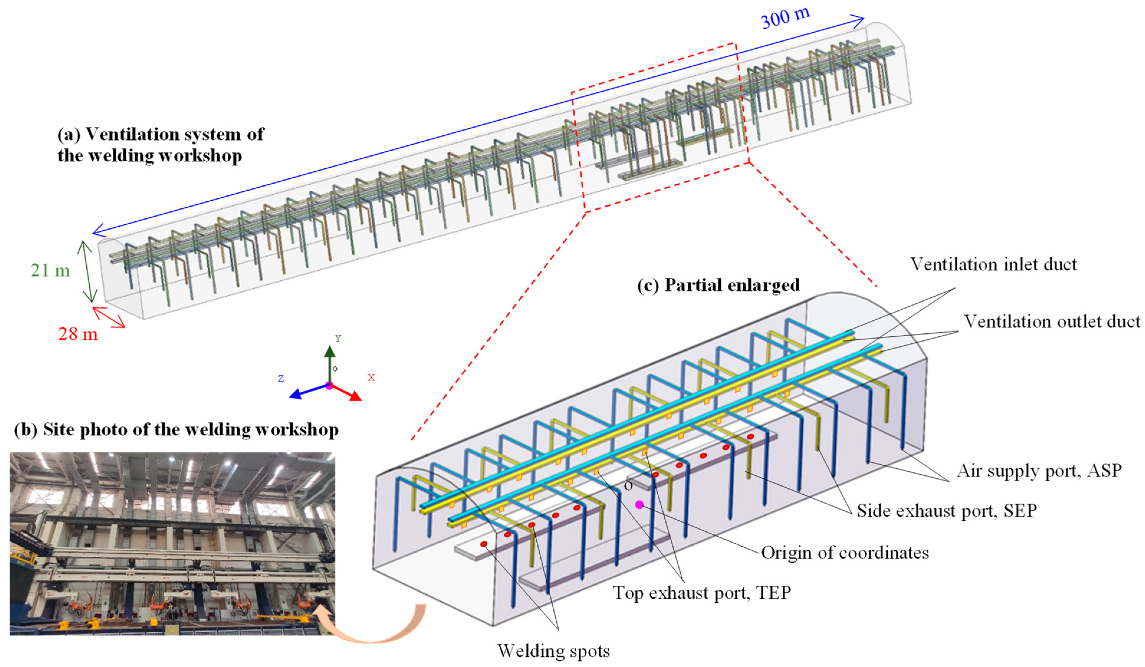
The simplified 3D geometric model of the welding workshop is shown in Figure 1.
The air supply port (ASP) measures 0.3 × 0.3 m with a height of 2 m. The dimensions of the side exhaust port are recorded as 0.3 × 0.3 m, with a height of 8 m (with a range of 3 to 8 m to be investigated through modeling). The size of the top exhaust port (TEP) is 1.0 × 1.0 m, with a height of 12 m. Due to the periodicity of the welding spot layout in the welding workshop, part of the welding spot layout is selected for flow field and dust concentration analysis.
The model is unstructured and meshed; the determinant values of the model grids range from 0.75 to 1, with a mean value of 0.85.
Numerical modeling is carried out using ANSYS Fluent v19.0. The air supply and exhaust ports are set as velocity inlets. Discrete phase model (DPM) is enabled. The number of continuous-phase iterations per DPM iteration is set at 10, the length scale is 60, and the injection type is surface. The SIMPLEC algorithm is adopted for the solution, and the second-order upwind scheme is adopted for spatial discretization, with more settings shown in Table 1. Notably, the mass flow rates of the two dust types were set equal to isolate the effect of density on fume transport, ensuring that all other variables remained controlled.

2.2.3. Model Validation

To verify the accuracy of the model, welding fume concentrations extracted from modeling results were compared with measured data. According to the method specified in GBZ/T192.1-2007 [21], the dust samplers (CCZ-20 type, Suzhou Yilian Electromechanical Technology Co., Ltd., Suzhou, China) were suspended at predetermined heights and conducted short-term fixed-point sampling at a flow rate of 20 L/min. During sampling, five welding stations were operating concurrently. Dust sampling was conducted using four samplers at four points simultaneously, with each session lasting 15 min, and the measurements were repeated three times. The dust concentration was then calculated based on the weight gain of the filter membrane before and after sampling, along with the flow rate and sampling duration.
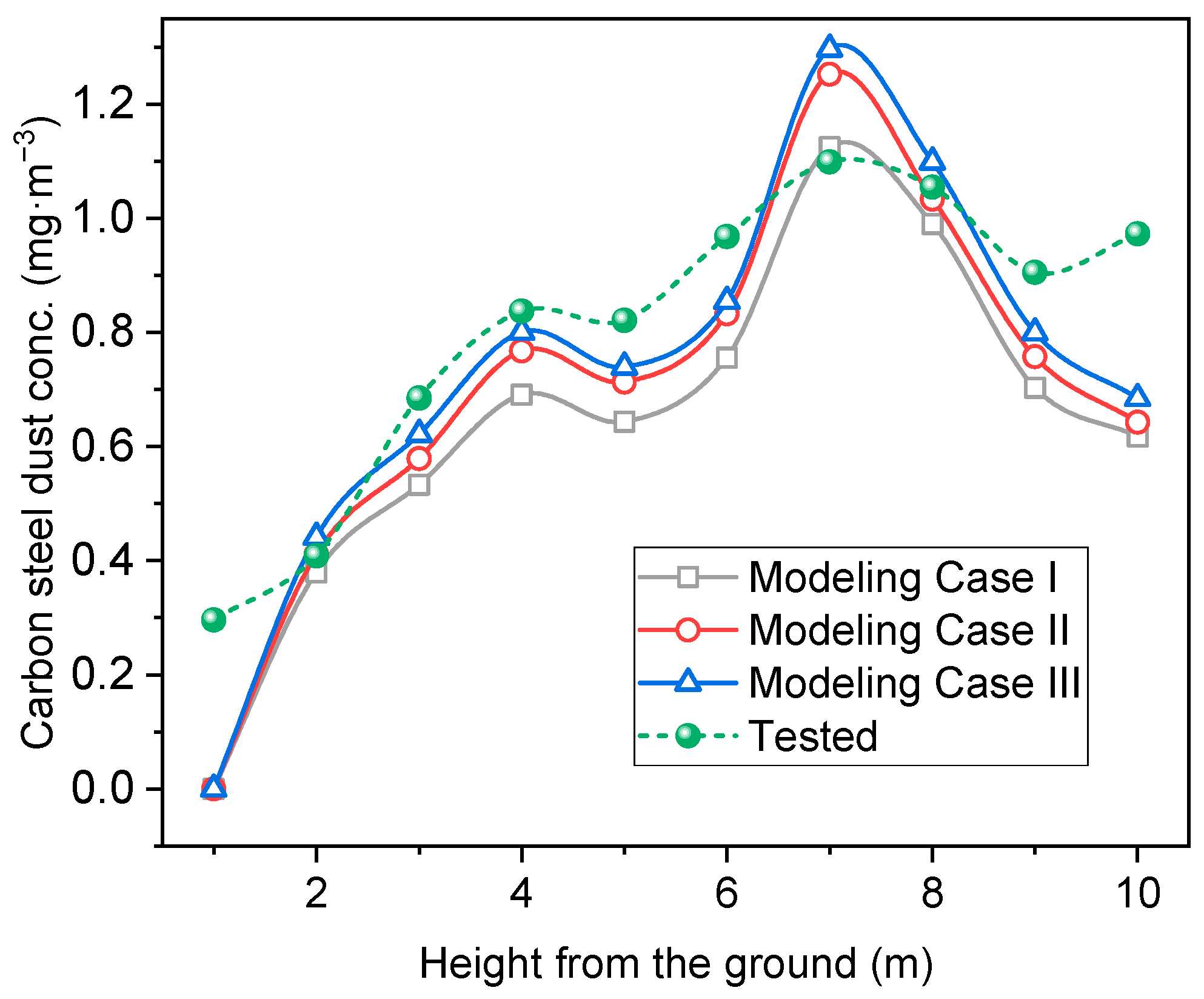
Figure 2 presents the measured and modeled average dust concentrations as a function of height at X = −6 m (1.5 m horizontally from the dust source) and at Z = 9, 17, 25, 33, and 41 m, under relatively stable dust concentration conditions in the welding workshop. To ensure grid independence, three progressively refined meshes were generated, with cell counts of 517,768 (Case I), 729,248 (Case II), and 1,012,845 (Case III), respectively. As shown in Figure 2, the differences among the three mesh resolutions are minor; notably, the results from Case II and Case III are in close agreement, with the height-dependent concentration discrepancies considered negligible. Therefore, the Case III mesh was adopted for all subsequent simulations, confirming that the model has passed the grid independence verification.
Furthermore, the measured and modeled concentration profiles exhibit a consistent trend of first increasing and then decreasing with height, with the two sets of values in reasonable agreement. This demonstrates that the numerical model is capable of reliably reproducing the actual measured results.

3. Results and Discussion

3.1. Analysis of Dust Diffusion Law

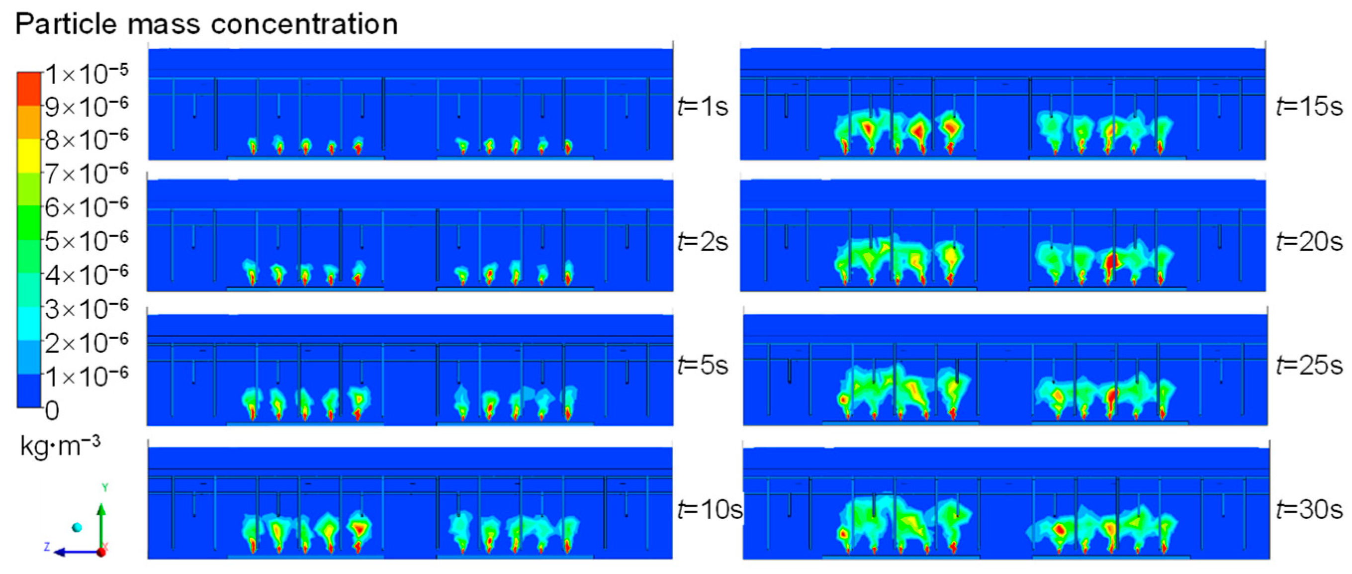
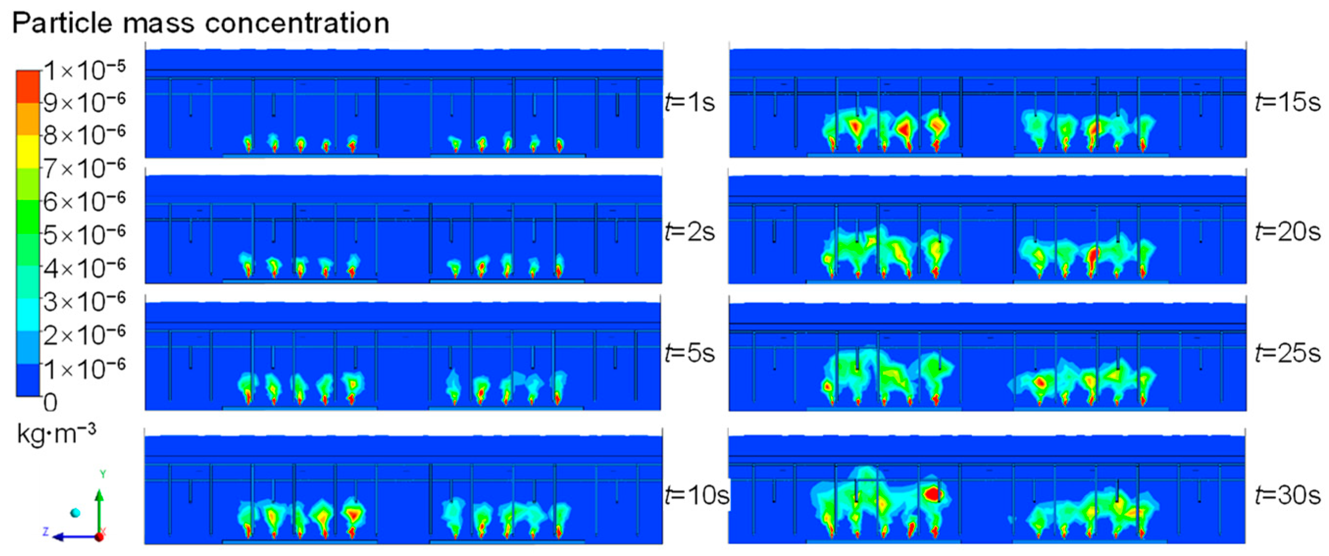
To investigate the diffusion and transportation law of welding fume, one case of numerical modeling was carried out with no ventilation. The dust particle mass concentration contours are shown in Figure 3 and Figure 4.
Dusts are raised from the welding spot due to hot air buoyancy. For 0~4 m height above ground, due to the large spacing, the diffusion law of multiple dust sources is just like that of single welding spot operation, and there is no mutual interference between welding spots in the low-height area.
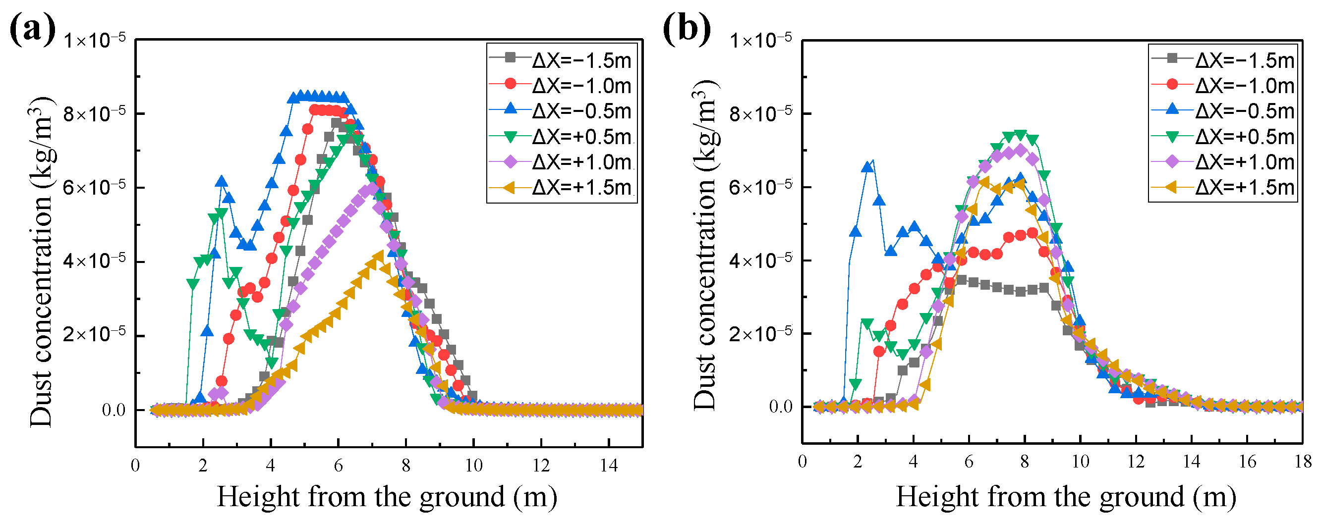
Further, the dust concentration nearby the welding spots was investigated. Vertical lines with distances of −1.5, −1.0, −0.5, 0.5, 1.0, and 1.5 m from the welding fume source in the Z = 20 m section were selected for monitoring. The dust concentration changes with height are shown in Figure 5.
With the increase in welding fume height along the vertical direction, the dust concentration increases first and then decreases. The dust concentration decreases with the increase in horizontal distance from the welding spot. This is mainly due to the diffusion of welding fume in the process of rising.
The density of welding fume has a great influence on dispersion. Carbon steel dust is predominantly concentrated within the vertical interval of 3–8 m, whereas aluminum alloy dust is concentrated within the 4–10 m vertical interval in the vertical direction. The peak value of carbon steel dust concentration is higher than that of aluminum alloy dust. When ΔX = −0.5 m, the maximum dust concentration of carbon steel is 8.2 mg/m3, while that of aluminum alloy is 5.9 mg/m3. Carbon steel dust concentration is 28.05% higher than that of aluminum alloy dust.
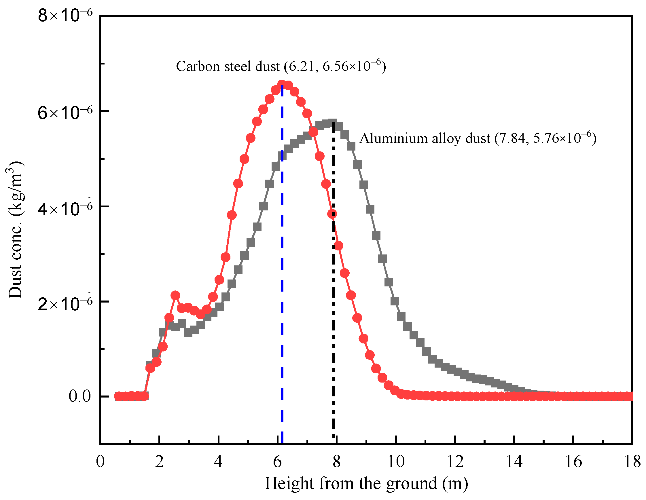
Figure 6 shows the distribution diagram of the average dust concentration at varying heights of lines, with ΔX= −1.5 to 1.5 m.
It could be found that the maximum concentration of carbon steel dust is 6.56 mg/m3, which is located at a height of 6.25 m from the ground, while the maximum concentration of aluminum alloy dust is 5.76 mg/m3, which is located at a height of 7.84 m. The difference between the two concentration peaks is 1.7 m. The main reason for this difference is that the density of aluminum alloy dust is lighter than that of carbon steel dust.
Another difference caused by welding material density is shown in the dispersion range. In the rising process of welding fume, entrainment drives the surrounding air to form a dust cloud suspension. By analyzing the average dust concentration along the height, it is found that the aluminum alloy dust with a concentration of more than 2 mg/m3 is mainly distributed in the 4~10 m height, while carbon steel dust, with a concentration exceeding 2 mg/m3, is primarily found at heights ranging from 3 to 8 m. The aluminum alloy dust concentration is slightly lower than the carbon steel dust concentration.

3.2. Study on the Influence of ESR

To study the influence of ventilation ESR on welding fume dispersion in the workshop, the airflow field and dust concentration distribution were investigated by setting ESR at 1.10 to 1.30. Among them, the air supply volume is always fixed at 13.56 m3/s (the actual air volume of the workshop), and the exhaust volume is calculated according to ESR. All ports are averaged by total air volume.
(1) Influence on the airflow field.
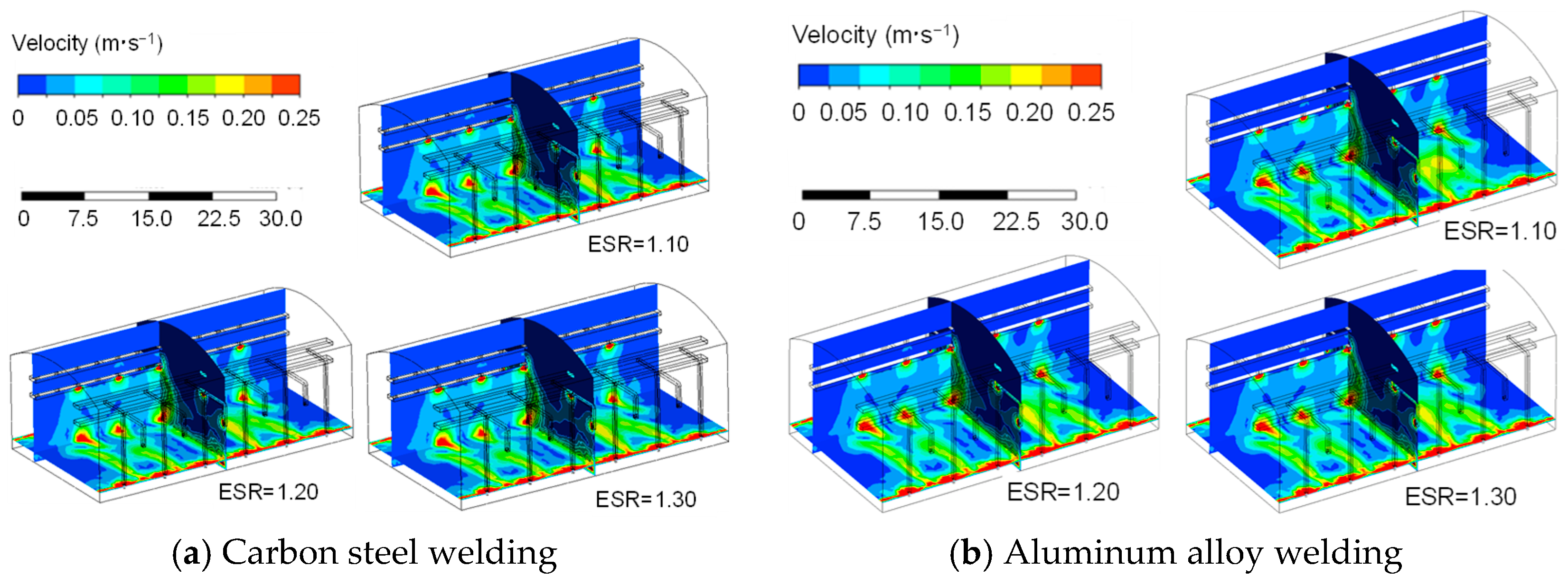
Figure 7 shows the velocity distribution contours of the stable airflow field during carbon steel and aluminum alloy welding operations, respectively.
It can be observed that fresh airflow is sent into the workshop from the air supply port (ASP), diffused around the ASP by jet action, and then flows out of the workshop under the negative pressure action at the TEP and the SEP. Under the same ESR, the airflow nephogram in the workshop is almost the same for the two kinds of welding materials. The main reason is that the particle size of welding fume produced by the two materials is small during welding operations, which has little influence on the airflow field in the welding workshop.
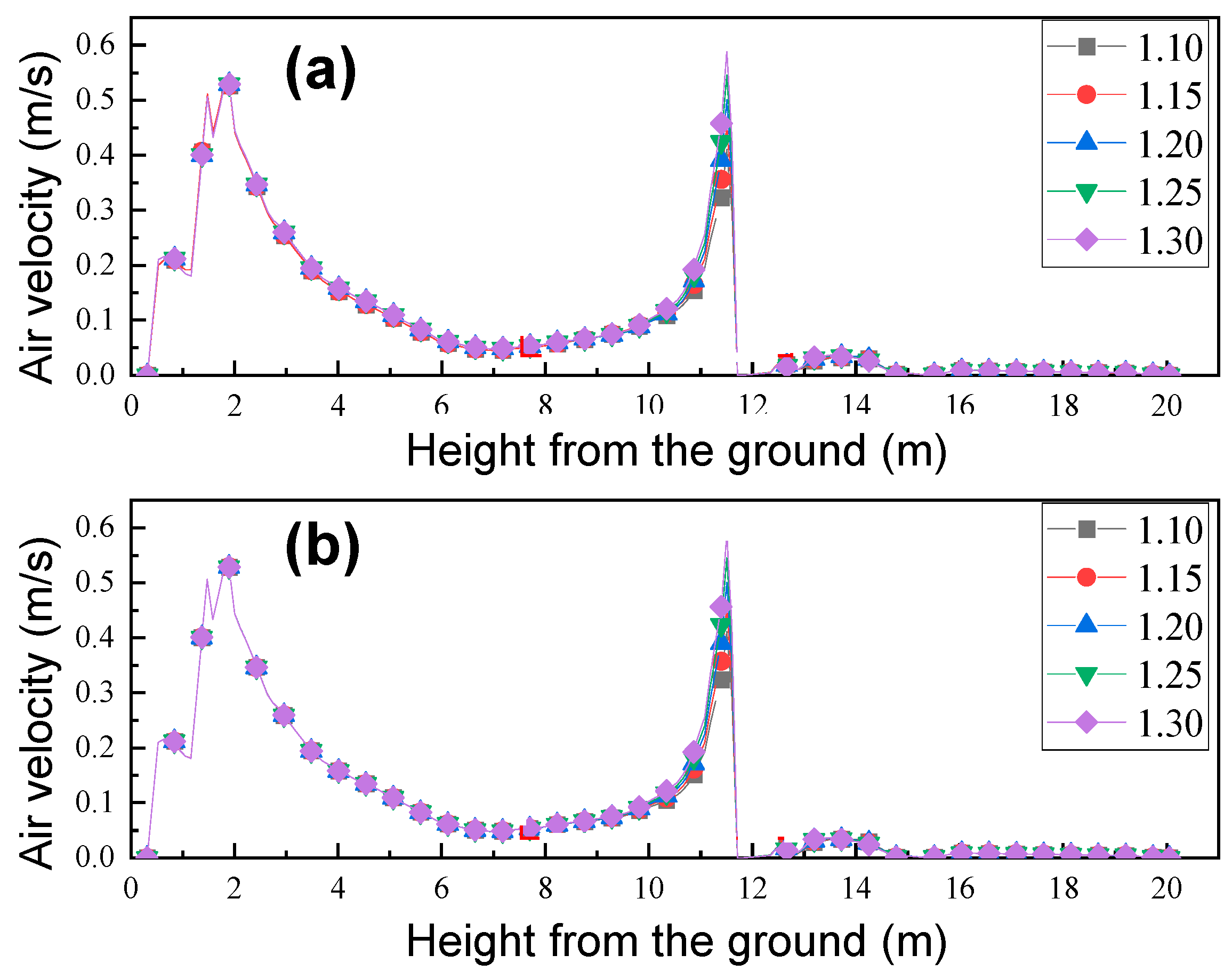
Select the vertical height at ΔX = 0.5 m away from the dust source as the monitoring line, and monitor the influence of air velocity of two different welding materials with height, as shown in Figure 8.
It can be seen that the air velocity exhibits a bimodal variation with height: it first rises and then falls, followed by a second rise and a subsequent sharp decline. The first peak (0–2 m) is dominated by the supply air jet. The dip (2–8 m) results from momentum decay of the supply jet with height due to turbulent mixing, coupled with weak buoyancy-driven flow at mid-elevations and the absence of mechanical exhaust in this region, which collectively make it a ‘transition zone’ between the supply- and exhaust-controlled regimes. The second peak (8–12 m) is driven by negative pressure from the top and side exhausts. This bimodal pattern is especially prominent in large-span workshops with a substantial vertical gap between the supply and exhaust openings, underscoring the need for careful SEP height optimization in the transitional trough.
In the first stage, the airflow velocity in the workshop changes due to the influence of air supply (the ASP is 2 m above the ground) during the process of 0~2 m above the ground. At this time, the maximum air velocity is about 0.54 m/s. Then, the air velocity decreases with the gradual increase in height at 2~8 m above the ground.
In the second stage, due to the influence of the TEP, the air velocity in the workshop increases gradually at 8~12 m above the ground and reaches the second peak value, and the size of the second peak value also increases with the increase in different ESRs. At 12~20 m above the ground, the air velocity drops sharply, mainly due to the obstruction of the exhaust pipe and the air supply pipe at the top.
The change in air volume at the TEP has little effect on the overall distribution trend of height air velocity in the workshop. It mainly affects the air velocity and the secondary peak value near the TEP (8~10 m), and the larger the ESR, the larger the air velocity, but the greater the power consumption.
(2) Effect on dust concentration.
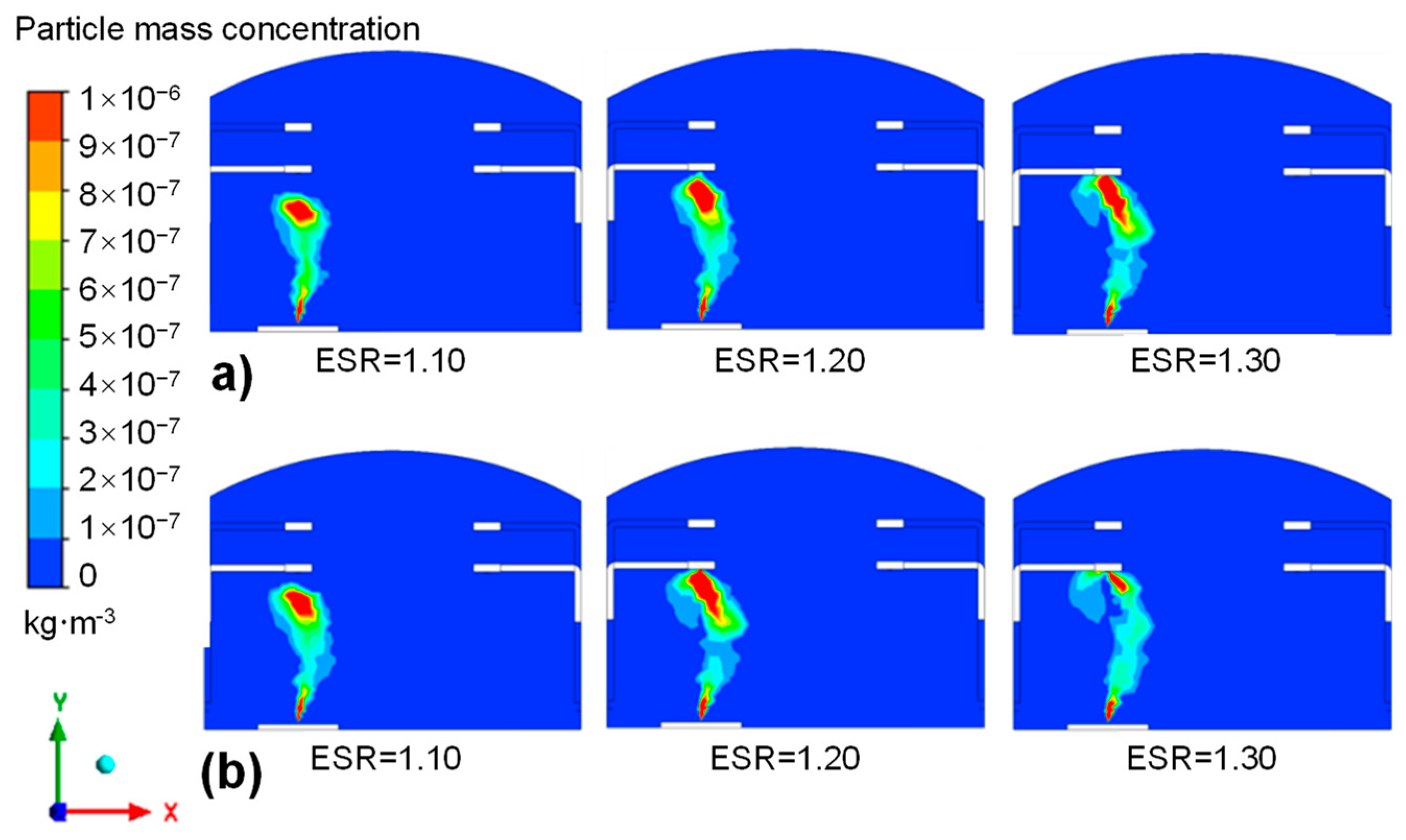
To analyze the influence of different air supply and exhaust volumes on dust concentration during welding operations, the middle section of the workshop (Z = 25 m) is selected as the monitoring surface to monitor the dispersion of welding fume of carbon steel and aluminum alloy under different ESR conditions, as shown in Figure 9.
For both kinds of welding fume, it is found that the welding fume moves upward under the action of hot air buoyancy, blast pushing, and exhaust suction, and the dust removal effect of the TEP is greater than that of the SEP. Compared with no-ventilation conditions, the faster the upward migration of welding fume, the smaller the lateral dispersion range, and the larger the ESR, the more obvious this phenomenon is.
It is known from the relevant literature [22,23,24] that the smaller the density and the smaller the particle size of welding fume, the faster it spreads. In cases of the same ESR, although the particle size of aluminum alloy welding fume is larger than that of carbon steel, its dispersion rate is faster than that of carbon steel dust, which is mainly due to the more important role played by the density of aluminum alloy.
On the whole, ESR has little influence on welding fume dispersion in the workshop, and it is enough to keep the current ESR, i.e., 1.10, in the workshop for the ventilation system.

3.3. Study on the Influence of Height of Side Exhaust Port

SEP heights significantly influence the ventilation system in the workshop. The SEP at different heights from 3 to 8 m above the ground was investigated in the welding workshop.
(1) Influence on dust diffusion.
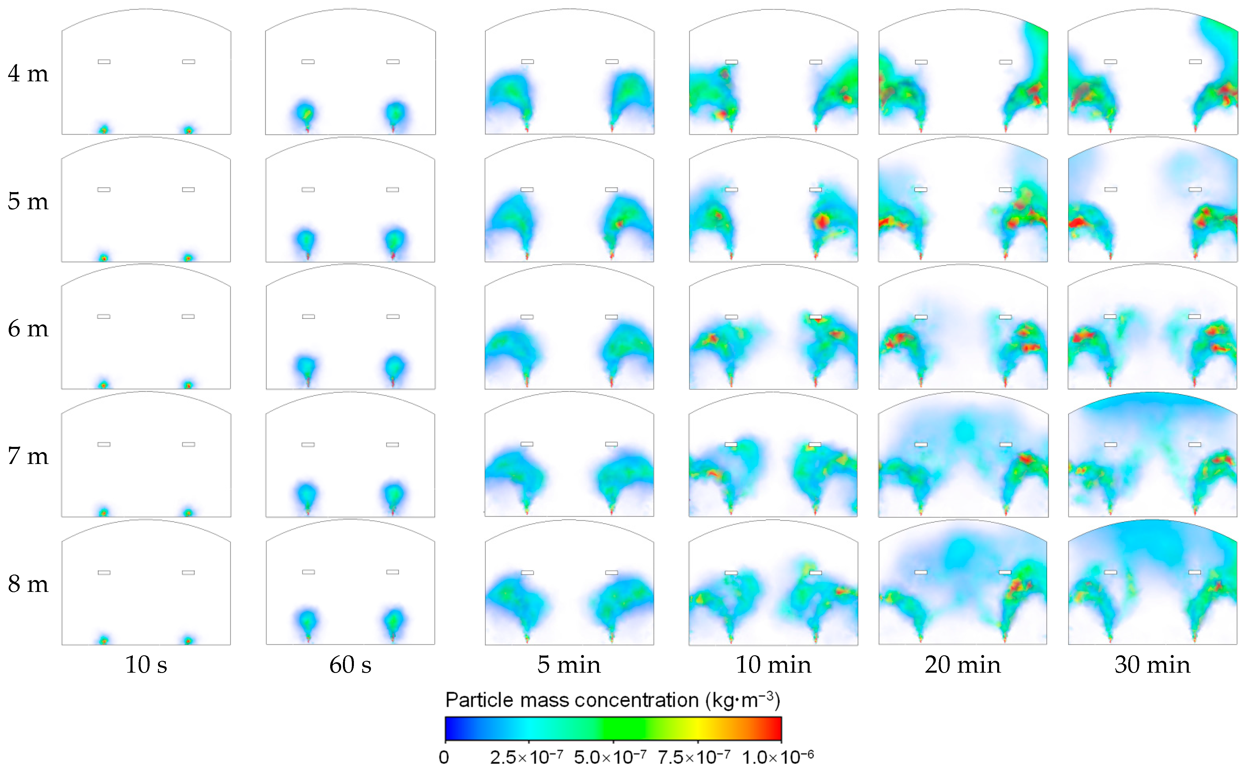
The concentration distribution of welding fume at different times was monitored, as shown in Figure 10; it is the concentration distribution diagram of the XOY plane in the welding workshop within 10 s to 30 min.
Across different SEP heights, the dust concentration distribution in the workshop remains approximately the same within 60 s. The welding fume moves upward under the driving effect of air supply, the suction effect of exhaust air, and the buoyancy effect of hot air.
For 5 to 10 min, dust is continuously discharged from the workshop through the side and TEPs, and it mainly accumulates in the lower and middle part of the workshop.
During the period of 20 to 30 min, it can be observed that the dust still mainly accumulates in the lower and middle part of the workshop when the height of the side exhaust is 6 m, but the dust has already dispersed to the upper part of the workshop when the height of the side exhaust is 4, 5, 7, and 8 m. The analysis shows that when the side exhaust position is 4 or 5 m above the ground, the generated welding fume is mainly discharged from the workshop through the ventilation SEP, and the position of the TEP has little effect on dust removal. When the dust is not exhausted completely by the side exhaust, the generated welding fume will move along the two side walls of the workshop, and the ventilation for dust exhaust effect is poor. When the side exhaust position is 7 or 8 m above the ground, the welding fume dispersed to the upper part of the workshop will be discharged from the workshop through the joint action of the top SEPs. With the increase in the height of the SEP position, the horizontal dispersion range of the welding fume is larger when it reaches the port height, and it is difficult to control the upward dispersion of the dust.
Overall, over about 15 to 30 min, dust generation and removal in the welding workshop reached a relatively stable state. When the SEP height is 6 m, the dust exhaust effect is the best; part of the dust is discharged from the SEP, and the other part is discharged from the TEP, and the dust at the top part of the workshop does not obviously accumulate. When aluminum alloy is used as the welding material, the dust concentration distribution law is similar over time, and the optimal side emission height is 5 m, with no obvious dust accumulation occurring at the top part of the workshop.
A SEP height that is too low brings the exhaust port too close to the supply port, causing airflow short-circuiting and poor fume capture. Conversely, a SEP height that is too high allows excessive lateral dispersion before the fume reaches the exhaust height, also impairing capture efficiency. In addition, the optimum SEP height corresponding to aluminum alloy dust is lower, mainly because of its smaller density, as it is easy to be sucked by side exhaust airflow and enter the SEP faster in the process of buoyancy with high-temperature airflow.
(2) Influence on the vertical distribution of dust concentration in workshops.
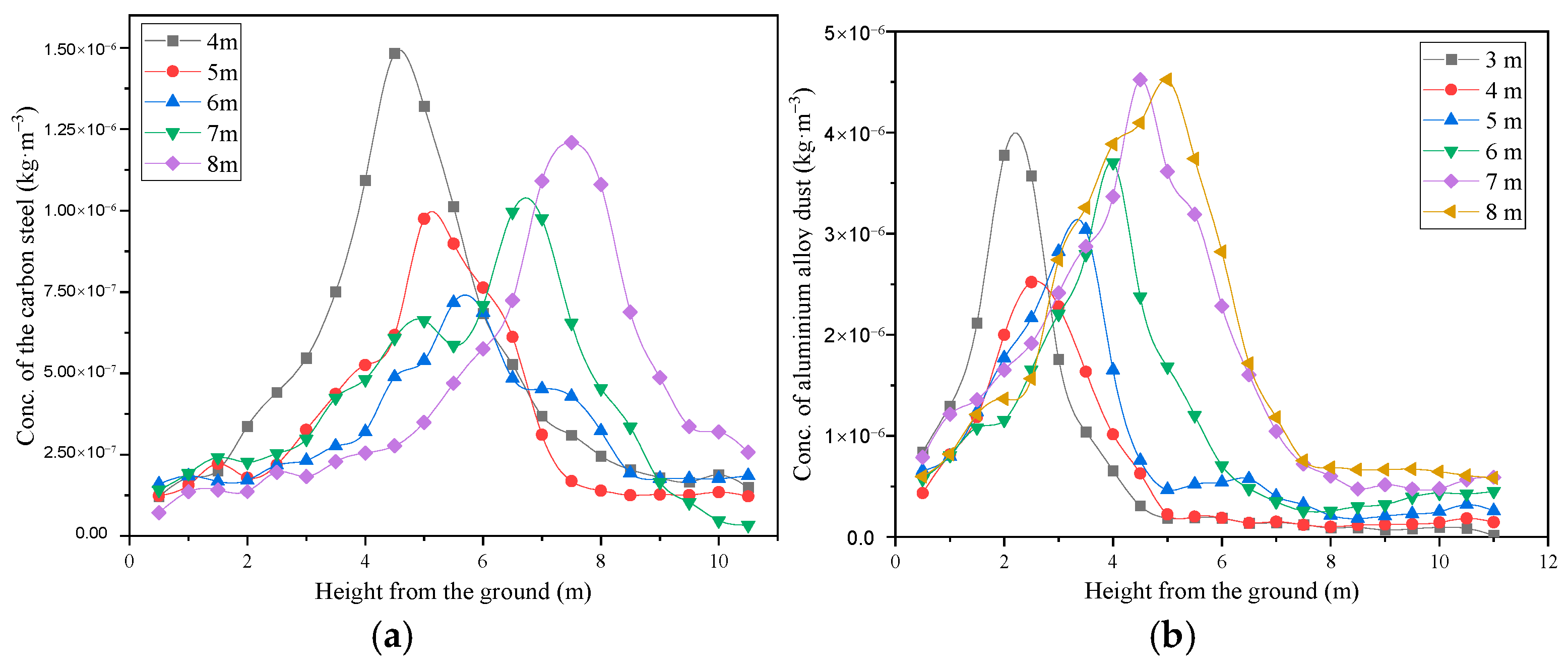
To analyze the influence of SEP height on dust dispersion in the welding workshop, vertical lines in the Z = 25 m section, with horizontal distances of −1.5, −1.0, −0.5, 1.0, and 1.5 m from the welding fume source, were selected for monitoring. The concentration distribution of welding fume with height is shown in Figure 11.
With the increase in height, the dust concentration increases first and then decreases. The peak value of dust concentration in the height direction decreases first and then increases with the increase in SEP height. The carbon steel dust corresponding to the SEP height of 6 m has the lowest concentration peak value of 0.6 mg/m3, which indicates that the ventilation dust exhaust effect is the best. The SEP height corresponding to the minimum concentration peak of aluminum alloy welding fume is 4 m, which is lower than that of carbon steel welding fume. The corresponding concentration peak is 3.0 mg/m3, which is higher than that of carbon steel dust.
The lower density makes aluminum alloy dust more easily carried by the rising thermal airflow, and during the ascent, it is drawn into the side exhaust airflow earlier and more rapidly. As a result, a substantial portion of the dust is exhausted at a relatively lower height (corresponding to a lower SEP height), causing the concentration peak to appear at a lower position. Combined with the analysis in Figure 12, it can be observed that aluminum alloy dust begins to be discharged within a shorter period (100–300 s), whereas carbon steel dust requires a longer time (200–600 s). This further indicates that aluminum alloy dust is more readily carried upward by the airflow and captured by the side exhaust port, thereby confirming the trend of its peak concentration shifting downward.
(3) Influence on the dust removal effect.
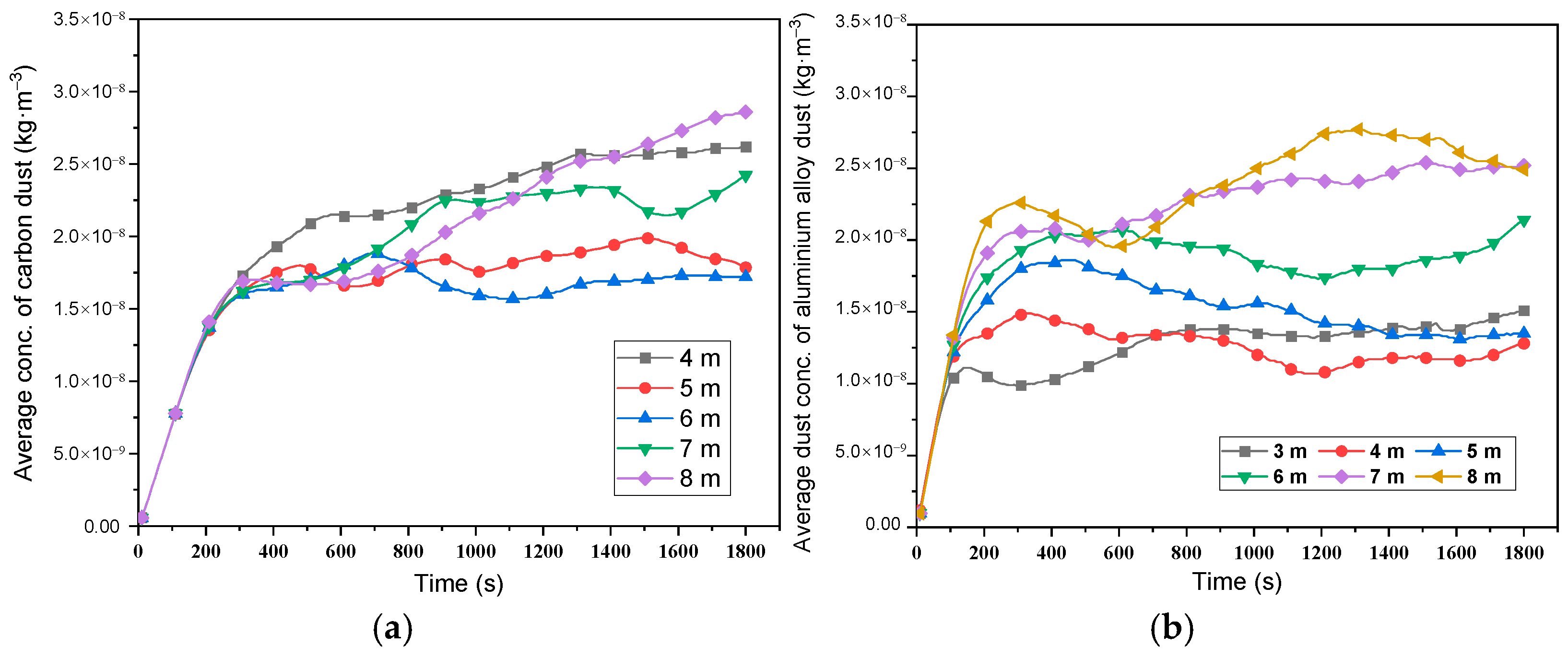
The impact of the overall ventilation and dust removal effect under varying SEP height is further explored, as shown in Figure 12.
For carbon steel welding fume, the average concentration in the workshop increases linearly with time and does not change with the height of the SEP during continuous welding operations for about 200 s. It indicates that the generated welding fume has not been discharged to the outside of the workshop during this period, and the dust does not reach the SEP or the TEP.
During 200 to 600 s, the rate of increase in welding fume concentration in the workshop decreased continuously. This shows that the welding fume generated during this period is gradually discharged from the workshop, and the concentration of welding fume is relatively stable in the range of 1.5 × 10⁻⁸ to 2.5 × 10⁻⁸ kg/m3. Among them, the dust removal effect is the worst when the SEP height is 4 m, and the dust removal effect is the best when the SEP height is 6 m.
With continuous welding and ventilation, dust generation and removal in the workshop reach a “dynamic equilibrium” after about 15 to 30 min. During this period, the dust removal effect among varying SEP heights is different. The average dust concentration in the workshop where the SEP is 6 m is lower than that of the other port-height cases.
Therefore, from the point of overall dust exhaust effect, it is suggested that the height of the SEP for carbon steel welding fume should be arranged near 5 to 6 m above the ground.
For aluminum alloy welding conditions, the average dust concentration in the aluminum alloy workshop is consistent with that in the carbon steel workshop within 100 s of continuous welding operations and gradually increases linearly with the increase in time, which indicates that the welding fume generated in this period has not been discharged to the outside of the workshop and the dust does not reach the SEP or the TEP. Compared with carbon steel dust, this period lasts for a shorter time, indicating that aluminum alloy dust is easier to discharge than carbon steel dust, mainly because aluminum alloy dust has a lower density.
During 100 to 300 s, the increasing speed of the concentration of aluminum alloy welding fume decreased continuously, indicating that the welding fume was gradually discharged from the workshop, and the concentration of welding fume at this period was in the range of 1.0 × 10⁻⁸ to 2.25 × 10⁻⁸ kg/m3. The dust removal effect is the worst when the SEP is 8 m, and the dust removal effect is the best (temporary) when the SEP is 3 m.
With the continuous welding operations and ventilation, the concentration of dust generated and discharged reaches a “dynamic equilibrium.” At about 400 s to 30 min, the dust removal effect among varying SEP heights is different. The average dust concentration in the workshop when the SEP is 4 m is lower than that of other exhaust port-height cases. Compared with carbon steel dust, the optimum height for aluminum alloy dust removal is lower, which is consistent with the analysis in Section 3.2.
Overall, from the point of dust removal effect, it is suggested that the SEP for removal of aluminum alloy welding fume should be arranged at a height of 4 to 5 m. Compared with carbon steel dust, the dust removal effect of aluminum alloy dust changes more noticeably with the SEP height, and the corresponding optimal SEP height is lower. This is mainly because the smaller density makes aluminum alloy dust easier to be sucked by the SEP during the rising process with high-temperature airflow.
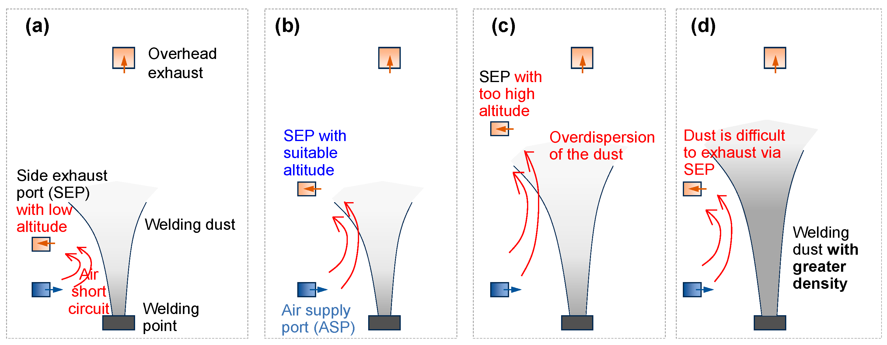
Based on the above analysis, the following schematic diagram of the mechanism of influence of SEP height on welding fume migration law is summarized (Figure 13).
The welding fume rises under the comprehensive ventilation effect of the buoyancy action of hot air, the driving action of air supply, and the suction action of exhaust air. In the process of rising, the surrounding air is sucked in, and the welding fume disperses laterally. At the top, the airflow carries dust to reach the exhaust pot, and at the bottom, the airflow continues to be supplied. Too low SEP will lead to too close a distance between side exhaust and ASPs, short-circuiting of airflow, and difficulty in inhaling welding fume. While too high SEP will lead to excessive horizontal dust dispersion and difficulty in inhaling dust when it reaches the exhaust port height. Carbon steel dust has higher density than aluminum alloy dust and is more difficult to be sucked by side exhaust airflow during the buoyancy process with high-temperature airflow, so the optimal height of SEP should be higher.

4. Conclusions

This study conducted CFD simulations to optimize the ventilation system of a 300 m × 28 m × 21 m welding workshop, with a focus on two adjustable parameters: the exhaust-to-supply air ratio and the side exhaust port height. The following conclusions are drawn:
(1) The mid-height trough (2–8 m) is identified as the critical zone for fume accumulation, indicating that the side exhaust port should be placed at 5–6 m to intercept rising fume before lateral dispersion. Increasing ESR beyond 1.10 yields only marginal improvement in this zone, suggesting that adjusting SEP height is more energy-efficient than increasing exhaust volume. This provides a quantitative basis for optimizing the vertical placement of exhaust inlets in large-span industrial buildings.
(2) The TEP consistently outperforms the SEP in dust removal. Increasing the ESR accelerates the upward migration of welding fume and reduces lateral dispersion, but the effect is marginal beyond ESR = 1.10; therefore, the current ESR of 1.10 is recommended to minimize energy consumption. This quantitative threshold provides a practical reference for the operation of ventilation systems in similar large-scale workshops.
(3) The SEP height critically affects dust capture efficiency. Too low SEP (e.g., 4 m) causes airflow short-circuiting with the supply port, while too high SEP (e.g., 8 m) allows excessive lateral dispersion before capture, both leading to degraded removal performance. Quantitatively, for carbon steel dust, the optimal SEP height of 6 m yields the lowest steady-state average concentration of 1.5 × 10⁻⁸ kg/m3, which is 22% lower than that at 4 m and 17% lower than that at 8 m. For aluminum alloy dust, the optimal SEP height of 5 m yields a steady-state average concentration of 1.8 × 10⁻⁸ kg/m3, which is 27% lower than that at 4 m and 36% lower than that at 8 m. The optimal height for aluminum alloy is lower than that for carbon steel, primarily because its lower density enables faster upward transport by thermal buoyancy and earlier capture by the side exhaust airflow, though the larger particle size of aluminum alloy fume partially counteracts this effect.
(4) The optimization approach adopted in this study—fine-tuning existing ventilation parameters rather than replacing the entire system—offers a cost-effective strategy for improving dust control in large-scale welding workshops, with immediate applicability to similar industrial facilities.
(5) We acknowledge that this study is based on a single workshop case, which may limit the generalizability of the quantitative results. Future work should extend the framework to multiple workshops with varying dimensions, ventilation configurations, and dust characteristics to establish broader empirical support for the optimal parameter recommendations and to develop generalized design guidelines.

Author Contributions

Conceptualization, B.Y.; software, B.Y., J.X., G.Z. and F.Z.; validation, J.L.; data curation, B.Y., T.W., X.P., J.C. and F.Z.; writing—original draft preparation, B.Y., G.Z. and Y.Y.; writing—review and editing, J.X., G.H., X.L. and J.L.; supervision, J.C.; funding acquisition, B.Y. and Y.Y. All authors have read and agreed to the published version of the manuscript.

Funding

This work was supported by the National Key R&D Program of China (2023YFC3010602), the Open Fund Project of NHC Key Laboratory for Engineering Control of Dust Hazard (KLECDH2024030101), and the Scientific and Technological Innovation Research Fund Project of the China Academy of Safety Science and Technology (2025KCY01).

Institutional Review Board Statement

Not applicable.

Informed Consent Statement

Not applicable.

Data Availability Statement

Data available on request.

Conflicts of Interest

Author Guishan He was employed by the Aerospace HIWING Security Technology Engineering Co., Ltd. The remaining authors declare that the research was conducted in the absence of any commercial or financial relationships that could be construed as a potential conflict of interest.

Symbols and Abbreviations

εTurbulence dissipation rate
ζRandom number satisfying a normal distribution
FxiOther forces acting on the particle
giComponent of gravitational acceleration in direction i (i = x, y, z)
kTurbulent kinetic energy
TIntegral time scale
TLLagrangian integral time scale
vpiParticle velocity component in the direction i (i = x, y, z)
vgiComponent of gas velocity in the direction i (i = x, y, z)
CFDComputational fluid dynamics
DESDetached Eddy Simulation
DPMDiscrete Phase Model
ESRExhaust-to-supply air ratio
LESLarge Eddy Simulation
SEPSide exhaust port
TEPTop exhaust port

References

  1. Zhu, Z.; Shi, Y.; Gu, Y. Research status of harm and comprehensive treatment of welding fume. Electr. Weld. Mach. 2022, 52, 1–12. [Google Scholar] [CrossRef]
  2. Li, C.; Han, D.; Wei, X.; Yang, J.; Wu, C. Health Risk Assessment of inhalable dust exposure during the welding and grinding process of subway aluminum alloy components. Buildings 2023, 13, 2469. [Google Scholar] [CrossRef] [Scilit]
  3. Ahmad, I.; Balkhyour, A.M. Occupational exposure and respiratory health of workers at small scale industries. Saudi J. Biol. Sci. 2020, 27, 985–990. [Google Scholar] [CrossRef] [Scilit] [PubMed]
  4. Wu, Y.; Luan, S.; Li, X. Fugitive emission characteristics of fume and dust from short-process electric furnace tap hole and optimization of dust hood. Atmosphere 2023, 14, 1829. [Google Scholar] [CrossRef] [Scilit]
  5. Ghanem, M.; Perdrix, E.; Alleman, L.Y.; Rousset, D.; Coddeville, P. Phosphate Buffer Solubility and Oxidative Potential of Single Metals or Multielement Particles of Welding Fumes. Atmosphere 2021, 12, 30. [Google Scholar] [CrossRef] [Scilit]
  6. Ren, X.; Yang, R.; Shi, E.; Cao, Z.; Yang, Y.; Zhang, X.; Li, J. Study on the near-field fume diffusion characteristics of overhead welding with single weld spot on large flat wall. Powder Technol. 2026, 473, 122233. [Google Scholar] [CrossRef] [Scilit]
  7. Wang, S.; Xue, S. Dust control and energy saving in welding workshop. J. Heilongjiang Univ. Technol. 2019, 19, 52–57. [Google Scholar] [CrossRef]
  8. Dahal, S.; Kim, T.; Ahn, K. Indirect Prediction of Welding Fume Diffusion inside a Room Using Computational Fluid Dynamics. Atmosphere 2016, 7, 74. [Google Scholar] [CrossRef] [Scilit]
  9. Yen, P.-H.; Chung, H.-N.; Cheng, W.-H.; Yuan, C.-S.; Tseng, Y.-L.; Yeh, C.-K.; Lien, C.-H.; Cheng, S.-W. Physicochemical characterization of welding and grinding fine particulates at a machinery plant: A comprehensive case study of workers’ health risk assessment. Atmos. Environ. X 2025, 25, 100319. [Google Scholar] [CrossRef] [Scilit]
  10. Frey, C.; Wahl, J.; Olschok, S.; Hagenlocher, C.; Graf, T.; Reisgen, U. Characterization of particles inside the metal vapor plume during laser beam welding in atmosphere and vacuum. Vacuum 2025, 233, 113964. [Google Scholar] [CrossRef] [Scilit]
  11. Rahul, M.; Sivapirakasam, S.; Sreejith, M.; Vishnu, B.; Vijayakumar, K. Concurrent reduction of the fume and Cr (VI) concentrations of inhalable and respirable particle using a new covered stainless-steel SMAW electrode. J. Environ. Chem. Eng. 2024, 12, 111632. [Google Scholar] [CrossRef] [Scilit]
  12. Nie, W.; Zhu, Z.; Liu, Q.; Hua, Y.; Liu, C.; Jiang, C.; Cheng, C.; Zhang, H. Numerical simulation of the dust pollution characteristics and the optimal dustproof air volume in coal washing plant screening workshop. J. Build. Eng. 2024, 87, 109025. [Google Scholar] [CrossRef] [Scilit]
  13. Park, S.; Kim, M.; Seo, J.; Choi, S. Numerical study on the internal ventilation of the engine room of a ship under construction. Alex. Eng. J. 2024, 100, 232–245. [Google Scholar] [CrossRef] [Scilit]
  14. Li, C.; Wang, H. Numerical simulation of welding aerosol diffusion based on plasma flow characteristics. Environ. Technol. Innov. 2023, 31, 103223. [Google Scholar] [CrossRef] [Scilit]
  15. Gao, T. The Research on the Optimization Design of Plant Natural Ventilation Based on the CFD Simulation Technology; Huazhong University of Science and Technology: Wuhan, China, 2011; Available online: https://kns.cnki.net/kcms2/article/abstract?v=jXpGf_Tis3DQpjjtJJTt9udYVa_l-_USYjPiG89dun9m4KU3ug2GU5QoYiAQXmwxhTiC242QdfkRwW8F7BZvy4_AL6gv_INdkNzNGQdE-xXWaIuzbrpv9uPPTpiaM773vBqaAczx04MvFs_0sdkl-OTw_fZmwmqMWnjW2yWs0INZaj4MZ9xZCQ==&uniplatform=NZKPT&language=CHS (accessed on 15 March 2026).
  16. Dong, H.; Li, G.; Li, J. CFD simulation of ventilation in large welding workshop in Shipyard. Ship Stand. Eng. 2022, 55, 69–74. [Google Scholar] [CrossRef]
  17. Gao, C.; Wei, B.; Liu, Q. Study on inducing ventilation system to control welding fume. Ind. Saf. Environ. Prot. 2019, 45, 77–81. Available online: https://kns.cnki.net/kcms2/article/abstract?v=sFGZ-GfRoEVBqLSvEhI5psUkcBZYiaJ9T9sZ_FbRlZoAoste4OJTYg_os_cptumlHlzTGnASghP8lXuouNeyZ0zhY2UL86t_9DvfcYTfm82Yvk_ga2OsxzV-PWZan09nYu0NLaZ-sopeWcmmmlepD56BIp45esxDZYf70-JBNc_UmL1V7ICV9g==&uniplatform=NZKPT&language=CHS (accessed on 15 March 2026).
  18. Wang, Q. Study on Exhaust Characteristics and Structure Optimization of Exhaust Hood in Welding Workshop. Master’s Thesis, Shandong University of Science and Technology, Qingdao, China, 2020. [Google Scholar] [CrossRef]
  19. Jiang, Z.; Lan, G.; Peng, Y. Theoretical study on dust distribution of multiple dust sources in welding workshop. Trans. China Weld. Inst. 2019, 40, 67–72. Available online: https://kns.cnki.net/kcms2/article/abstract?v=sFGZ-GfRoEWxTLzawokwTxWIJPm6Z0G_KGeE5wz3Hi5hxnJ_D-rjX_eHzCVPRLekQfC5cyvhHyKvqpv9EhZmXLceQKXxgTdf600jb1Zd755QrXJEGpS_YBI-uBK9blnkxcd6nHlmgKYcq9F7837gK2CAle3zu5eJw8zAYp9TUY7Yh2gAlaJTzA==&uniplatform=NZKPT&language=CHS (accessed on 15 March 2026).
  20. Zhang, G. Numerical simulation analysis and prevention of dust emission in downwind and upwind conditions of coal mining face. Mod. Min. 2024, 40, 187–190. Available online: https://kns.cnki.net/kcms2/article/abstract?v=sFGZ-GfRoEWZXm-ogQPqsjIW9q2j9m-kiAAnxP7pBuP39Qgq9opRb4LjRee_0P1L_SgdBTdR04WueUynbC172NsQ3hiWHNqrwMil9ZH50RQnkRzr0GYDA3xnPBO0Zcxfhqc7cU6cZX0EvSSsZHifkdGpMgGzRLZHDCT2Dup1SndUmMgj2jaK0w==&uniplatform=NZKPT&language=CHS (accessed on 15 March 2026).
  21. GBZ/T 192.1-2007; Method for Determination of Dust in the Air of Workplace Part 1: Total Dust Concentration. The Ministry of Health of the People’s Republic of China: Beijing, China, 2007.
  22. Sun, Z.; Fang, B. Stress analysis and movement study on construction tunnel dust. Coal Technol. 2016, 35, 176–178. [Google Scholar] [CrossRef]
  23. Yan, J. Study on Smoke Characteristics of Small Welding Workshop and Response Surface Analysis. Master’s Thesis, Liaoning Technical University, Fuxin, China, 2021. [Google Scholar] [CrossRef]
  24. Zhang, W.; Li, H. Simulation of Welding Fume Flow Field in Industrial Plant; China Environmental Protection Industry: Beijing, China, 2024; pp. 62–65. Available online: https://kns.cnki.net/kcms2/article/abstract?v=sFGZ-GfRoEVuzCihTqx45vUVZRNt5tSFU5Y3Na9vOa7VxjsmUXZ0x0WJRJrEO-pkPH7Oh0lUUdzXS6rQVa8LU5zWF64hzRW2irDC1D8MzDoYakN9Mtb2VzBTWGDg8PPTccQb9dsnDnimCUCwoksFXtJzHMvC6LgOwv0ByURACXw_cilHfCB4hA==&uniplatform=NZKPT&language=CHS (accessed on 15 March 2026).
Figure 1. Schematic diagram of the three-dimensional geometric model of the welding workshop.
Atmosphere 17 00843 g001
Figure 2. Comparison analysis of carbon steel dust concentration measured and modeled.
Atmosphere 17 00843 g002
Figure 3. Concentration contours of carbon steel welding fume in the X = −7.5 m section.
Atmosphere 17 00843 g003
Figure 4. Concentration contours of aluminum alloy welding fume in the X = −7.5 m section.
Atmosphere 17 00843 g004
Figure 5. Variation in the (a) carbon steel and (b) aluminum alloy welding fume concentration with height near the welding spots.
Atmosphere 17 00843 g005
Figure 6. Comparison of average dust concentration distribution at different heights for 30 s produced by two materials (The vertical line indicates the peak.).
Atmosphere 17 00843 g006
Figure 7. Air velocity contours with varying exhaust-to-supply air ratios, esr, in the welding workshop.
Atmosphere 17 00843 g007
Figure 8. Variation in air velocity with height for different welding materials (a) Carbon steel dust case; (b) Aluminium alloy dust case.
Atmosphere 17 00843 g008
Figure 9. Dust concentration of (a) carbon steel and (b) aluminum alloy welding fume varying with exhaust-to-supply air ratio, ESR.
Atmosphere 17 00843 g009
Figure 10. Distribution of carbon steel dust concentration with varying side exhaust port (box in the figure) height in the workshop.
Atmosphere 17 00843 g010
Figure 11. Concentration distribution of (a) carbon steel and (b) aluminum alloy welding fume with height.
Atmosphere 17 00843 g011
Figure 12. Evolution of average dust concentration in the workshop of (a) carbon steel and (b) aluminum alloy welding fume.
Atmosphere 17 00843 g012
Figure 13. Schematic diagram illustrating the influence of side exhaust port (SEP) height on welding fume dispersion and capture: (a) low SEP causes airflow short-circuiting, (b) suitable SEP enhances fume capture, and (c) high SEP leads to excessive lateral dispersion; (d) welding dust with greater density. The arrow indicates the wind direction.
Atmosphere 17 00843 g013
Table 1. Dust source parameter setting.
ItemsCarbon Steel, CSAluminum Alloy, AA
Density (g/cm3)3.84 g/cm32.25
Diameter DistributionRosin–RammlerRosin–Rammler
Min. Diameter (m)0.1 × 10−60.5 × 10−6
Max. Diameter (m)7.5 × 10−57.5 × 10−5
Mean Diameter (m)3.1 × 10−64.7 × 10−6
D10 (μm)1.080.67
D50 (μm)4.713.04
D90 (μm)26.8916.79
Spread Parameter3.53.5
Velocity (m/s)00
Temperature (K)20002000
Total Flow Rate (kg/s)2 × 10−62 × 10−6
Turbulent DispersionStochastic TrackingStochastic Tracking
Time Scale Constant0.150.15
Disclaimer/Publisher’s Note: The statements, opinions and data contained in all publications are solely those of the individual author(s) and contributor(s) and not of MDPI and/or the editor(s). MDPI and/or the editor(s) disclaim responsibility for any injury to people or property resulting from any ideas, methods, instructions or products referred to in the content.