Article

Trace Extraction and Repair of the F Layer from Pictorial Ionograms

1
Communication Engineering School, Hangzhou Dianzi University, Hangzhou 310018, China
2
State Key Laboratory of Space Weather, Chinese Academy of Sciences, Beijing 100190, China
*
Author to whom correspondence should be addressed.
Atmosphere 2024, 15(7), 769; https://doi.org/10.3390/atmos15070769
Submission received: 9 May 2024 / Revised: 20 June 2024 / Accepted: 25 June 2024 / Published: 27 June 2024
(This article belongs to the Section Upper Atmosphere)

Abstract

:
Publicly available ionograms are often in the form of pictures. This paper proposes a novel algorithm for extracting and repairing the F layer traces from pictorial ionograms. Extensive efforts have been invested in ionogram autoscaling and critical parameter identification to improve the efficiency of scaling algorithms. To obtain the parameters of the F layer automatically, it is necessary to accurately extract the F layer trace. However, research on F layer trace extraction with repair is relatively limited. The method employed in this study makes full use of the characteristics of different types of echoes on the ionograms, and the procedure includes noise preprocessing, coupling noise processing, and trace repair. To enhance the applicability of the repair, two different automatic filling algorithms are adopted to repair the F layer trace. The aim of this paper is to present an adaptive algorithm to automatically extract and repair F layer traces from different pictorial ionograms. The results of Hainan Fuke ionograms illustrate the reliability of the F layer trace extraction and trace repair.

1. Introduction

The ionosphere, a crucial layer of the near-Earth space environment, is influenced by various factors [1]. These factors encompass complex plasma processes, interplanetary magnetic fields, and the propagation of geomagnetic activity through the troposphere [2,3,4]. The ionospheric parameters of TEC and foF2 are sensitive to space weather and exhibit a pronounced response to meteorological variations [5]. Accurate predictions of TEC in ionospheric modeling rely on estimating the realistic values of NmF2 and hmF2 [6], which requires obtaining a pure F layer trace from the ionogram. Meanwhile, the ionospheric critical frequency of the F2 layer can be directly obtained from the ionogram, and a pure and smooth F layer trace can also contribute to the automated acquisition of higher precision of F2. The F layer of the ionosphere, located approximately 150 km above the ground, primarily consists of plasma generated by the ionization of individual oxygen atoms through ultraviolet radiation. Many modern electronic communication and navigation systems are affected by the ionospheric environment when the signals penetrate and propagate through the F layer [7]. With the advancement in present satellite navigation, wireless communication, and space research, real-time monitoring and ionospheric forecasting have become increasingly crucial to meet the growing demands for accuracy and risk mitigation.
With the availability of advanced ionosondes and progress in the research of the space environment, the nuances in signal characteristics on raw ionograms are becoming distinguishable. This progress has been supported by the development of software and hardware techniques. Much work has been dedicated to developing generalized algorithms for the autoscaling of vertical incidence ionograms with different features. The ARTIST (Automatic Real-Time Ionogram Scaler with Trueheight) [8,9,10], developed by the University of Lowell, identifies radio wave modes and extracts ionospheric characteristics from the Digisonde ionograms, based on the hyperbolic trace-fitting method and wave polarization information. Fox and Blundell separated a continuous trace into individual traces associated with the various ionospheric layers using extrapolations and checked the characteristics of each flagged trace to determine whether to merge it with other traces [11]. Ding et al. implemented a method for the autoscaling of layers based on empirical orthogonal functions combined with image-matching techniques [12]. Jiang et al. proposed a new template-matching algorithm using the quasi-parabolic segment model and empirical orthogonal functions to extract the features of F1 and F2 layers [13]. In Jiang et al. [14], the researchers’ simulated annealing algorithm was applied to improve vertical incidence ionogram autoscaling by searching the best-fit parameter of the quasi-parabolic segment model. Chen et al. developed a method mainly based on mathematical morphology, graph theory, and ionospheric echo features to extract F layer traces, and later proposed a new algorithm for ionogram autoscaling with separated O and X waves [15,16]. Scotto designed an alternative procedure based on template matching and image recognition techniques [17]. Related research later extended to Es, F1, and F2 layers to further optimize its effectiveness [18,19,20]. Lan et al. presented a method to obtain the critical frequency of O and X waves by using the NeQuick2 model and image technology [21]. This achievement was mainly accomplished through a pattern recognition technique that combined math. Huang et al. used Spatial Attention U-Net to identify elongated, overlapping, or compact signals and recover O and X waves and Es from highly contaminated ionograms [22]. Since the output formats of ionograms obtained from different ionosondes are different, publicly available ionograms are often in the form of pictures. To obtain the parameters of the F layer automatically, it is necessary to accurately extract the F layer trace. However, research on F layer trace extraction and repair is relatively limited. In this paper, we propose a new method to extract and repair the F layer trace for pictorial ionograms. The method applied in this work emphasizes obtaining pure and smooth F layer traces for pictorial ionograms containing different types of noises. Meanwhile, we attempt to fill the gaps of the fractured traces with mathematical morphology and alterable filling methods, depending on the image features of the gaps. The aim of this study is to introduce a comprehensive approach to enhance the accuracy and generality of ionogram image processing procedures, mainly including extraction and repair of F layer traces.
Figure 1 shows the original ionogram from an ionosonde and the method described in this paper. The pictorial ionogram is obtained based on the transmission and reception of signals with different frequencies. A typical pictorial vertical ionogram is shown in Figure 1a: the horizontal coordinate represents the detection frequency, and the vertical coordinate represents the virtual height. Different types of signals, including O and X waves, other waves, and noises, are labeled by different colors. As shown in Figure 1b, the main procedure is typically structured in three steps: noise preprocessing, coupling noise processing, and trace repair. Firstly, the useless information including grid lines, multiple reflection traces, and discrete noise is suppressed in noise preprocessing. Secondly, the noises adjacent to the F layer trace are deleted by Canny edge extraction and characteristic parameters. Finally, the repair region is searched and the gaps are filled with the orthogonal extension filling method and matrix filling method, and then the continuous skeleton can be obtained. The article is organized as follows: Noise preprocessing is introduced in Section 2. Coupling noise processing is introduced in Section 3. Trace repair is introduced in Section 4. The conclusion is given in Section 5.

2. Noise Preprocessing

2.1. Invalid Signal Suppression

In this paper, the pictorial ionogram of the DPS-4D is used to extract the F layer trace. The image is initially converted to grayscale to obtain the two-dimensional information. When the non-zero pixels cover the whole row or column, the corresponding pixels will be considered grid lines and deleted. The multiple reflection traces are generated due to multiple path reflections between the ionosphere and the Earth, which interfere with the extraction of the F layer trace [23]. Their height can be approximated as an integer multiple of the height of the main trace. As the energy is absorbed by the medium during propagation, the grayscale values of the multiple reflection traces decrease with the number of reflections. However, after being converted into binary images, the grayscale values of partial multiple reflection traces differ very little from those of the main trace. In order to avoid the influence of the unattenuated multiple reflection traces in the binary images, it is necessary to attenuate the grayscale values of the multiple reflection traces, thereby suppressing their interference with the subsequent steps.
The mass center and the average grayscale values at each frequency are first calculated. The multiple reflection traces can be suppressed by subtracting the average grayscale values above the mass center and adding the average grayscale values below the mass center. Since some ionograms have infinite slopes near the critical frequency, the virtual height distribution of the traces near the critical frequency becomes larger, leading to an increased sensitivity to the mass center retrieval. Therefore, the 50th pixel above the mass center is set as the split point. The non-zero pixels above the split point subtract the average grayscale values, while the pixels below the split point add the average grayscale values. For a two-dimension image of size m*n, the formulas are expressed as:
g ( x , y ) = g ( x , y ) m e a n ( x ) × sgn [ y ( M ( x ) + 50 ) ]
m e a n ( x ) = y = 1 n g ( x , y ) × sgn [ g ( x , y ) ] y = 1 n sgn [ g ( x , y ) ]
M ( x ) = y = 1 n g ( x , y ) × y × sgn [ g ( x , y ) ] y = 1 n y × sgn [ g ( x , y ) ]
sgn ( u ) = { 1 , u > 0 0 , u = 0 1 , u < 0
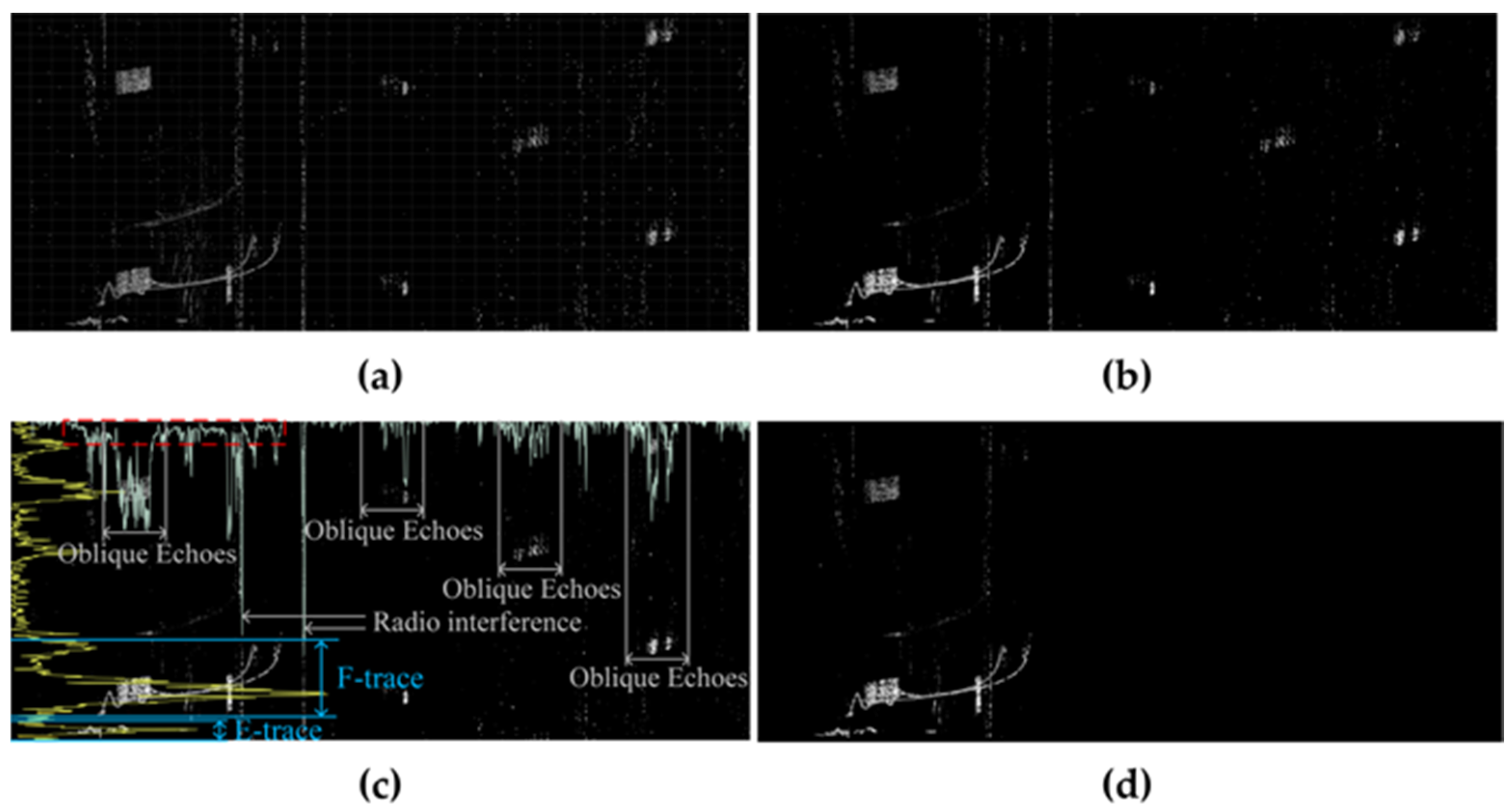
where g is the grayscale value of each pixel in the binary ionogram, (x, y) corresponds to the frequency and virtual height, respectively, sgn is the step function, and mean and M denote the average grayscale values and mass center of non-zero pixels at each frequency. It can be seen in Figure 2b that the multiple reflection traces and discrete noise are effectively suppressed after the median filtering and multiple reflection trace suppression. The E layer trace, the multiple reflection traces, and the remaining discrete noise require further processing.
Next, we adopt the integration projection method for further optimization. Compared with other signals, the F layer trace manifests a long continuum on the horizontal and vertical integration projections. In order to find the F layer trace, we traverse through the horizontal and vertical integration projections to find the longest connectivity area. Due to the presence of small gaps in the F layer trace, the start and end points of the firstly identified longest connectivity area do not represent the actual distribution of the F layer trace. Thus, we search for the next non-zero value in the up and down directions on the horizontal integration projection, respectively. If the zero-interval length is less than the threshold, the gap can be ignored and the previous start and end points are replaced by the new ones. Alternatively, if the zero-interval length is more than the threshold, the search process is terminated and the start and end points of the longest connectivity area are determined. We retain the pixels between the start and end points and delete the rest of the pixels in the frequency and virtual height axes. The result of the invalid signal suppression is presented in Figure 2, after the multiple reflection traces suppression and the integration projection method. Compared with the original binary ionogram shown in Figure 2a, we can find successful suppression of the multiple reflection traces and discrete noise after median filtering and suppression based on the mass center in Figure 2b. As shown in Figure 2b, the F layer signal and upper virtual height region have obvious differentiation in grayscale values. Figure 2c presents the results of the horizontal and vertical integration projection. Different components are labeled: the yellow and pale green lines denote the projection results of the virtual height and frequency axis, respectively. In Figure 2c we can see that, the distribution of different interference components on the virtual height axis is more continuous than the frequency axis, which causes distinct projection effects in the two axes. The longest connectivity area determined is marked in Figure 2c as the red dashed area. In Figure 2c, we can see that the projection result of the virtual height axis is more continuous than that of the frequency axis for the discrete noise. Therefore, the noises and traces are difficult to distinguish effectively on the virtual height axis. The longest connectivity area determined is marked in Figure 2c as the red dashed area, which can help distinguish between the noises and traces. Figure 2d presents the result through the integration projection method, and the large parts of the noises are effectively suppressed.

2.2. Inverse Iteration Based on 8-Connected Components

The 8-connected component method can be employed to distinguish the F layer trace from other signals based on the ionospheric structural characteristics [24]. This method is achieved by finding the trace with the maximum 8-connected components, which is identified as the F layer trace. The method is suitable for high-quality ionograms with complete traces and less noise diffusion. When ionograms contain large-scale discrete noise and diffuse E layer traces, they may be incorrectly identified as strongly connected components due to the filling and dilation operations of morphological processing. In order to improve the generalization of the method, we propose the method of inverse iteration based on 8-connected components. Three nodes are created based on the processing order: (1) before the morphological processing; (2) after the morphological processing, and the trace with the maximum 8-connected components is extracted. (3) The trace with the maximum 8-connected components is extracted again for the trace obtained in (2). When the number of non-zero pixels in the node (1) is approximately equal to that of (3), the extracted trace is the F layer trace. When large-scale discrete noise exists, the trace extracted in (3) tends to be discrete noise, which is significantly different from the trace in (1). Therefore, we use the ratio of the results of (1) and (3) as the judging criterion. We further consider the situation when there is a large fracture in the F layer trace. As the third node (3) contains no morphological processing before extracting the trace with the maximum 8-connected components, the large fracture will affect the result. The dispersion rate, D, is used to analyze the discrete degree of the whole ionogram, which is expressed as:
d ( x , y ) = { u = 1 1 [ v = 1 1 ( 1 sgn [ g ( x + u , y + v ) ] ) ] , g ( x , y ) > 0 0 , g ( x , y ) = 0
D = x = 1 m ( y = 1 n d ( x , y ) ) x = 1 m ( y = 1 n sgn ( d ( x , y ) )
where d(x,y) is the dispersion degree of a single pixel, which can be calculated by counting the number of zero pixels in the range of the 8-connected adjacent domain. The key point of inverse iteration is to overcome the problem of the direct use of maximum 8-connected component extraction. We hope to achieve both high-precision F layer trace identification and F layer trace integrity through an iterative process. Therefore, the determination parameter is required to measure the effectiveness of a single iteration process, which is mainly applied to detect the existence of anomalies. We define N as the anomaly identification parameter for result calibration and iteration control, which is expressed as:
N = sgn ( 1 1 u + 1 × N U M 1 N U M 3 × D 2 D 1 )
where N U M 1 and N U M 3 denote the retention of valid information in the nodes (1) and (3), which can be obtained by counting the number of non-zero pixels in the ionogram corresponding to nodes (1) and (3). D 1 and D 2 are the dispersion rates of nodes (1) and (2) and can be calculated with Formula (6). u is the iteration number.
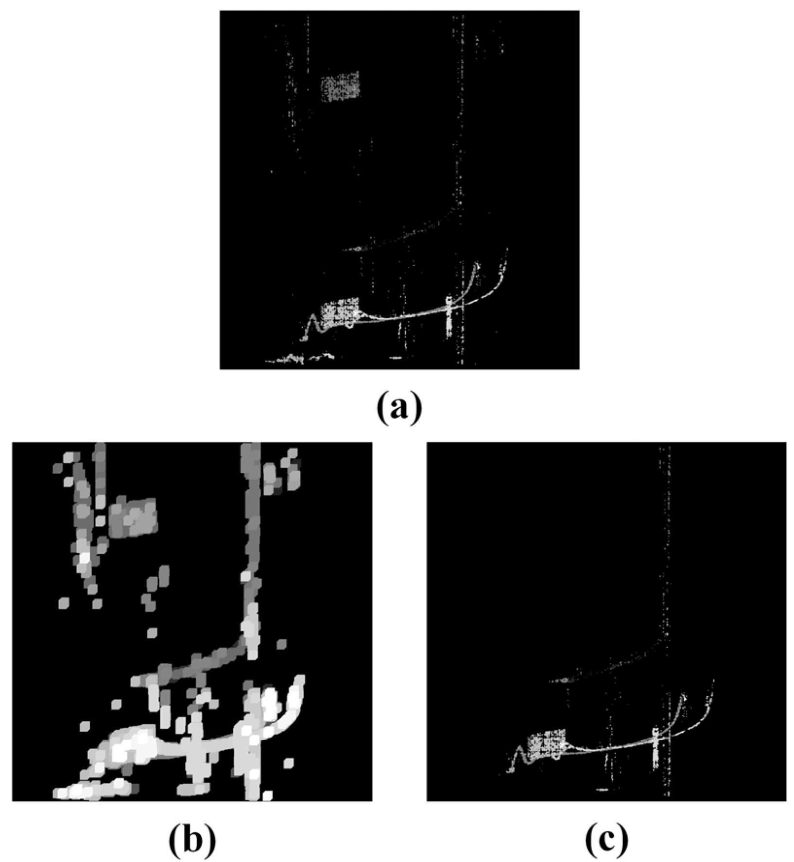
Owing to the features of maximum 8-connected component extraction, N U M 1 must be greater than or equal to N U M 3 . An ideal extraction result is divided into two situations. The first is successful extraction in the early stages of iteration, where noises exist extensively, thus resulting in a larger D 2 / D 1 . The second is successful extraction in the later stages of iteration, where the u is large, and the ionogram is clean. This will lead to N U M 1 and N U M 3 converging to approximately equal values, which is the same situation with D 1 and D 2 . Based on the analysis above, when N = 0, the result of the current iteration does not provide a positive effect, and three new nodes are generated once again and substituted into the function to enable iteration. As the number of iterations increases, the pixels corresponding to these three nodes gradually decrease with each iteration, thus increasing the sensitivity. Therefore, the iteration number u is used as the adjusting parameter. This procedure intensifies the distinction between the F layer trace and the surrounding noises. As shown in Figure 3, Figure 3a shows the image after invalid signal suppression, Figure 3b shows the image after morphological processing, and Figure 3c shows the image after inverse iteration. The results show that the algorithm is effective.

3. Coupling Noise Processing

3.1. Canny Arithmetic Edge Extraction

After the inverse iteration based on 8-connected components, the F layer trace is effectively distinguished from other signals. However, the noises adjacent to the F layer persist, which is shown in Figure 3c. To further denoise the image, we introduce the Canny operator for edge detection and extraction [25]. The procedure is shown as follows:
(1)
Smooth the ionogram by building a Gaussian filter.
(2)
Calculate the gradient size and direction for each pixel. Horizontal, vertical, positive diagonal, and negative diagonal are defined as four special directions. The gradient direction of a pixel within 22.5 degrees clockwise and counterclockwise in one of the four special directions is replaced by the special direction. Traverse through all the pixels and reserve the pixels that have the largest gradient value in the gradient direction. Then, delete the rest of the pixels.
(3)
Set two thresholds, tg and td, the values of which are 0.2 times and 0.05 times the maximum gradient value. Pixels with a gradient value greater than tg will be marked. For pixels with a gradient value between tg and td, if at least one pixel in the 8-connected adjacent domain has a gradient value greater than tg, they are also marked. Then, unmarked pixels are deleted to remove the weak edges. The residual noise is further deleted by the threshold-based weak edge identification.
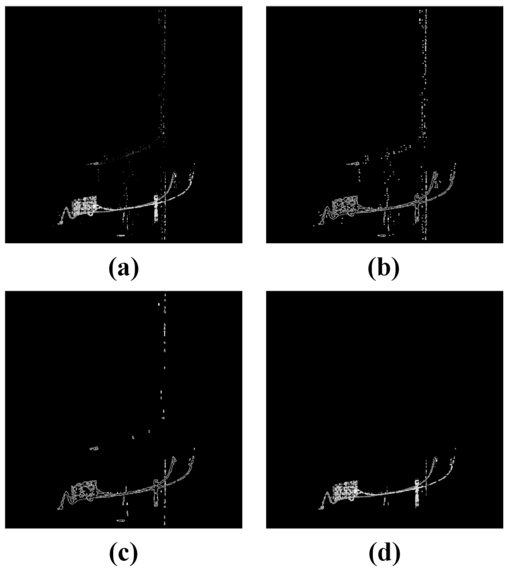
Canny edge extraction offers the advantage of leveraging contour edge characteristics, which helps to further remove the partly adjacent noises. We use a morphological closure operation to fill the hollow part inside the contoured F layer trace. Then, the maximum 8-connected component extraction is applied again to extract the F layer trace. As shown in Figure 4, Figure 4a shows the original image before Canny, Figure 4b shows the image after Gaussian filter and gradient processing, Figure 4c shows the edge extraction result after weak edge elimination, and Figure 4d shows the result after the morphological closure operation and maximum 8-connected component extraction. The result shows that the noises are further attenuated.

3.2. Coupling Noise Removal

When noises are coupled to the F layer trace, it is difficult to remove them from binary ionograms. Due to the proximity of the spatial distance, the F layer traces are susceptible to corruption when applying the aforementioned approach. Hence, we choose to incorporate the color information to aid in subsequent processing. To map the signal information contained in the binary ionograms after the Canny algorithm back to the original ionogram with the signal labeled by different colors, the coordinate of every zero pixel in Figure 4d is searched and recorded. Then, all the pixels corresponding to the recorded coordinate in the original ionogram are deleted.
In the ionogram of DSP-4D, the color of the F layer trace is different from that of other signals. To effectively identify and delete coupling signals while maintaining the integrity of the F layer trace, we introduce characteristic parameters that utilize both signal features and the screening feature of the method above. The average pixel is the parameter that records the number of occurrences of a signal. The dispersion rate in this part analyzes the degree of dispersion of each signal type with different colors. The retention rate quantifies the proportion of signals that are preserved after the previous steps compared with the original ionogram. We compare the characteristics of the F layer trace with that of other signals to distinguish them. Table 1 illustrates the statistical results of the characteristic parameters with a large number of ionograms in Hainan.
Based on the comparison results, we find definite distinctions in the dispersion rate and retention rate, and the signals of Vo+, Vo−, X+, and X− have lower dispersion rates and higher retention rates. Therefore, we retain only the signals with the four lowest dispersion rates and the four highest retention rates. We define a search window, W(X,Y), where the size of Y equals the vertical height axis size, n, and the size of X is 3 in this work. The four signals with both the lowest dispersion rate and highest retention rate are defined as C1, C2, C3, and C4. Then, the number of pixels whose color does not belong to C1 to C4 inside the search window is recorded, and the search window is moved from the minimum frequency to the maximum frequency. The difference between the two neighboring counted pixel numbers is calculated, and the interval corresponding to the maximum difference value is marked. The corresponding marked pixels are deleted, and the O and X waves can be separated based on C1 and C2. As shown in Figure 5, the coupling noises are effectively removed through the characteristic parameters, and the separated O and X waves are used for the subsequent repair work.

4. Trace Repair

4.1. Gap Filling

When considering ionograms with both O and X waves, identifying the points between gaps becomes challenging due to their mutual interference along the two axes. Using the previously extracted separated ionogram, we traverse each ionogram separately and record the number of non-zero pixels corresponding to each frequency. Firstly, we set up the logical variable f ( x ) with the initial value of 0. If the value of the frequency axis projection result, P F , is non-zero, it indicates that the scanning is in the continuous trace area, and the new non-zero value does not represent the start or end point of the continuous region. However, a projection value change from non-zero to zero implies that the frequency is adjacent to the end point of the present continuous region. Similarly, when P F has a value of zero, it indicates that the scanning is in the gap region, and a projection value from zero to non-zero implies the start point of the continuous region. The value of f ( x ) follows the data mutation of the projection value of the frequency axis, while the start point of the gap is defined as F s t a r t ( n ) , and the end point of the gap is defined as F e n d ( n ) . The formulas are expressed as:
f ( x ) = P F ( x ) P F ( x 1 )
F s t a r t ( n ) = x 2 n 1       n = 1 , 2 , , N 2 1
F e n d ( n ) = x 2 n + 1       n = 1 , 2 , , N 2 1
where N is the non-zero number of quantities in f ( x ) , and x n is the location of the nth non-zero value in f ( x ) .
Mathematical morphological operations inevitably change the actual shape of F layer traces, leading to systematic bias [15]. Previous work has utilized and optimized smooth polynomial functions such as spline and curve fitting to compensate for this bias [11,20]. As the method in this paper focuses on extracting continuous and complete F layer traces, we prioritize effective repair based on the ionogram before mathematical morphological operations. Apart from acquiring the frequency coordinates F s t a r t ( n ) and F e n d ( n ) , it is crucial to automatically and precisely acquire the virtual heights in the repair region.
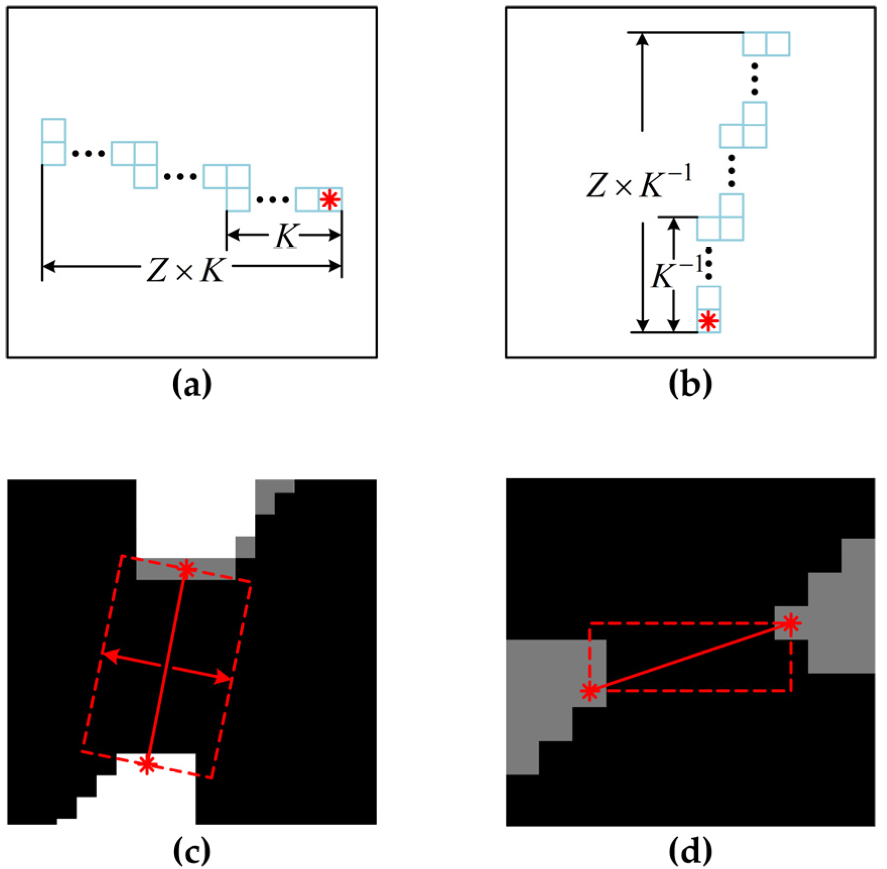
Initially, the binary ionogram undergoes a morphological closure operation to fill internal holes and small breaks. The virtual height of each non-zero pixel in F s t a r t ( n ) and F e n d ( n ) is searched and exploited to calculate the mean value, which is used to locate the start and end points of the repair region. To eliminate contamination caused by interference pixels, outliers need to be removed before calculation. H s t a r t and H e n d are defined as the start and end points of the virtual height, which can be calculated by Formula (2). Once we acquire the comprehensive data on the repair region, we can calculate the slope, K, based on the start and end points. Subsequently, depending on the slope, K, and the features of the repair area, two different methods are adopted in this paper. In order to enable the repair results to smoothly match the gap, the slope, K, and the thickness of the region on the left and right sides need to be considered. The first method is based on the extension in the direction orthogonal to the slope, K, and the extension length, Z, can be expressed as follows:
Z ( n ) = { [ ( k = 0 z P F ( F s t a r t ( n ) k ) ) + ( k = 0 z P F ( F e n d ( n ) + k ) ) ] × K 2 × ( z + 1 ) ,   | K | < 1 [ ( k = 0 z P H ( H s t a r t ( n ) k ) ) + ( k = 0 z P H ( H e n d ( n ) + k ) ) ] 2 × ( z + 1 ) × K ,   | K | 1       n = 1 , 2 , , N 2 1
where z determines the scope of the thickness search, which can be set to a proper integer. Figure 6a shows the orthogonal extension diagram when |K| ≥ 1, and Figure 6b shows the orthogonal extension diagram when |K| < 1. As shown in Figure 6c, the repair region is marked in the red box, and the red asterisks indicate the start and end points of the gaps. When extension length Z is below 1, it means the extension cannot be performed, and the aforementioned approach becomes ineffective. Another alternative is the matrix filling method, which utilizes the connecting lines as the diagonal of the matrix, and the matrix filling repair result is shown in Figure 6d. The two methods characterize the slope flexibly, adaptively repair different gaps, and enhance the robustness of ionograms with different qualities.

4.2. Trace Skeletonization

The skeletonized image preserves the essential shape information of the structure, including ports, intersections, and inflection points, while leaving the main area of the binary ionograms unchanged. Simultaneously, skeletonization reduces the tracing width to one single pixel, thereby enhancing the efficiency and accuracy of the structure. This paper describes the process of topological refinement for binary ionograms using the Zhang-Suen skeleton extraction algorithm [26] in the following steps:
(1)
Traverse each pixel of the ionogram and set up iteration parameters f1 and f2. Initialize the two parameters to 0. Select the pixels in the axial and diagonal adjacency domain, which fulfill the following three requirements: 1. the number of non-zero pixels belongs to the interval [2, 6]; 2. the number of 0–1 jumps observed in the clockwise direction is 1; 3. the four pixels in the axial adjacency domain are recorded clockwise as p1, p2, p3, and p4, respectively, and satisfy p2 × p4 × p6 = 0 and p4 × p6 × p8 = 0. Then, delete the pixels and mark f1 = 1.
(2)
Change the judgment condition in (1) to p2 × p4 × p8 = 0 and p2 × p6 × p8 = 0 and redetermine the conditions. If there is a pixel satisfying the conditions, delete it and mark f2 = 1.
(3)
Repeat (1) and (2) until f1 × f2 = 0, i.e., there is no pixel satisfying all the conditions in (1) or (2).
As shown in Figure 7a, we can see that all the gaps in the separate O and X waves are successfully searched (marked with red lines). Figure 7b presents the final trace repair result, in which the gaps are filled with highlighted pixels. Figure 7c shows the skeletonization result extracted from the repaired image, and a clean and continuous skeleton is obtained.

5. Conclusions

This paper presents a novel method to improve the performance of F layer trace extraction and repair for pictorial ionograms. We make full use of the characteristics of different types of echoes and use reasonable algorithms to extract the F layer trace and repair the trace by filling the gaps. We first suppress the multiple reflection traces with a split point determined by the mass center and apply the integration projection to remove the invalid frequency band. Anomaly detection and correction for large-scale discrete noise is achieved through inverse iteration of 8-connected components. To further delete the discrete noise and coupling noise attached to the F layer trace, we use Canny edge extraction and introduce characteristic parameters including dispersion rate and retention rate to identify the O and X waves. Depending on the morphological characteristics, the orthogonal extension and matrix filling methods can smoothly and successfully bridge gaps in the extracted F layer trace.
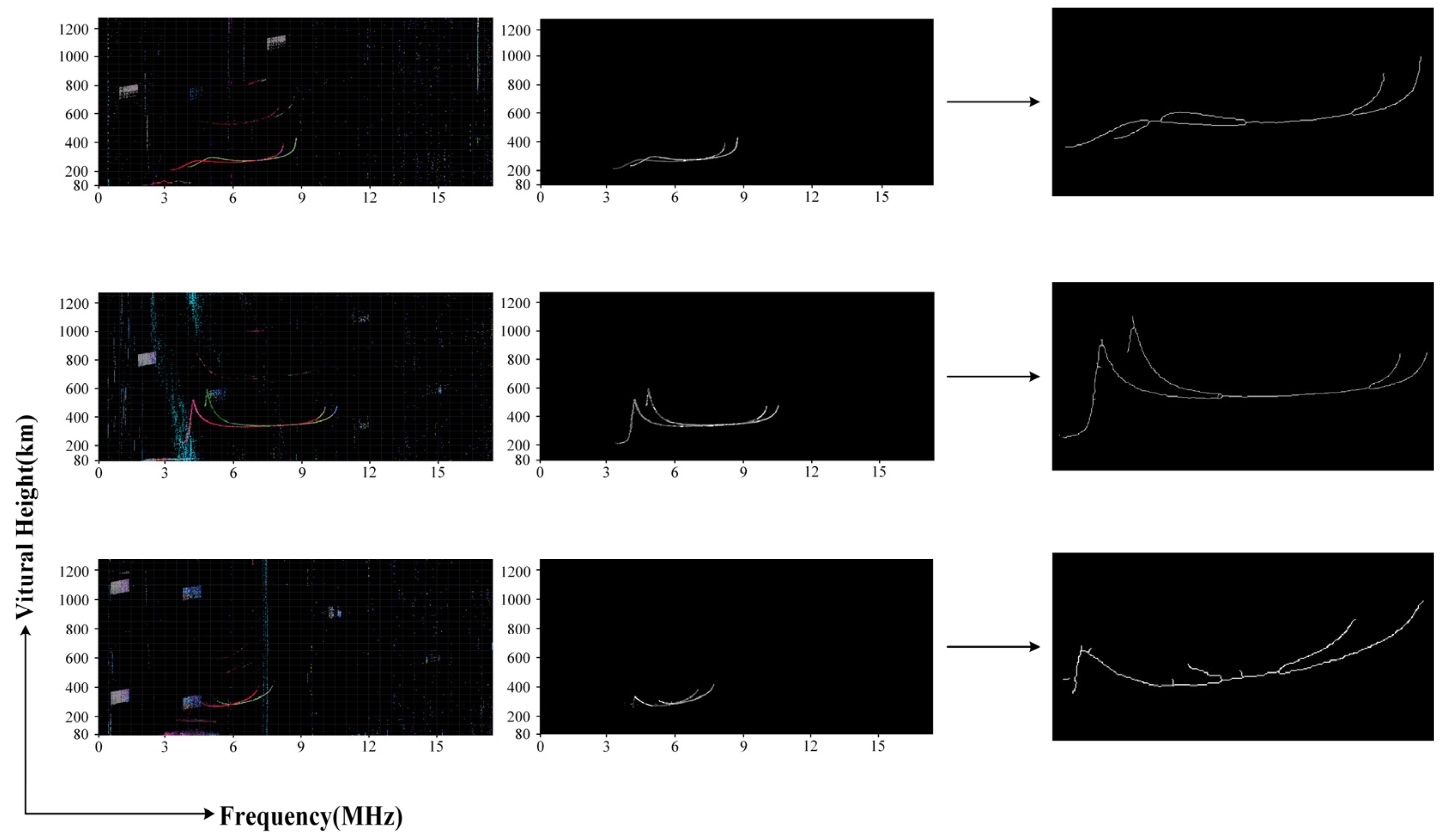
To verify the effectiveness of the proposed method, three typical ionograms from the Hainan Fuke station presented in Figure 8 are used to demonstrate the universality and flexibility. The first ionogram is of high quality without obvious noises, the second ionogram contains large-scale discrete noise attached to the F trace, and the third ionogram is highly contaminated by a coupling block oblique signal and a fixed frequency broadcast signal. The skeletonization results show that the method has fairly good performance in dealing with various ionograms. The F layer traces can be extracted and repaired effectively in ionograms with different qualities. The experimental results demonstrate that the performance of the algorithm is stable and satisfactory. Future work will focus on extracting and repairing all the traces under different conditions.

Author Contributions

Conceptualization, L.Q. and J.W.; methodology, J.W.; investigation, Z.Q.; validation, J.W.; formal analysis, C.Y.; resources, C.Y.; visualization, K.W.; funding acquisition, L.Q. and J.W. All authors have read and agreed to the published version of the manuscript.

Funding

This project was supported by the Specialized Research Fund for State Key Laboratories.

Institutional Review Board Statement

Not applicable.

Informed Consent Statement

Not applicable.

Data Availability Statement

The ionograms of Hainan Fuke were obtained from the Chinese Meridian Project website: https://data.meridianproject.ac.cn (accessed on 2 September 2023).

Acknowledgments

We appreciate the editors and the anonymous reviewers for their insightful comments and suggestions to improve this paper. We also thank the Specialized Research Fund for State Key Laboratories for its support.

Conflicts of Interest

The authors declare no conflicts of interest.

References

  1. Muldrew, D.B. Nonvertical propagation and delayed-echo generation observed by the topside sounders. Proc. IEEE 1969, 57, 1097–1107. [Google Scholar] [CrossRef]
  2. Bakhmetieva, N.V.; Grigoriev, G.I. Study of the Mesosphere and Lower Thermosphere by the Method of Creating Artificial Periodic Irregularities of the Ionospheric Plasma. Atmosphere 2022, 13, 1346. [Google Scholar] [CrossRef]
  3. Rastogi, R.G.; Patel, V.L. Effect of interplanetary magnetic field on ionosphere over the magnetic equator. Proc. Indian Acad. Sci. 1975, 82, 121–141. [Google Scholar] [CrossRef]
  4. Danilov, A.D.; Lastovicka, J. Effects of geomagnetic storms on the ionosphere and atmosphere. Int. J. Geomagn. Aeron. 2001, 2, 209–224. [Google Scholar]
  5. Borchevkina, O.; Karpov, I.; Karpov, M. Meteorological Storm Influence on the Ionosphere Parameters. Atmosphere 2020, 11, 1017. [Google Scholar] [CrossRef]
  6. Venkatesh, K.; Pallamraju, D.; Dalsania, K.P.; Chakrabarty, D.; Pant, T.K. Evaluation of the performance of F-layer peak height models used in IRI-2016 over the Indian equatorial and low latitudes. Adv. Space Res. 2024, 73, 3797–3807. [Google Scholar] [CrossRef]
  7. Zhbankov, G.A.; Danilkin, N.P.; Maltseva, O.A. Influence of the ionosphere on the accuracy of the satellite navigation system. Acta Astronaut. 2022, 190, 194–201. [Google Scholar] [CrossRef]
  8. Reinisch, B.W.; Huang, X. Automatic calculation of electron density profiles from digital ionograms: 1. Automatic O and X trace identification for topside ionograms. Radio Sci. 1982, 17, 421–434. [Google Scholar] [CrossRef]
  9. Huang, X.; Reinisch, B.W. Automatic calculation of electron density profiles from digital ionograms: 2. True height inversion of topside ionograms with the profile-fitting method. Radio Sci. 1982, 17, 837–844. [Google Scholar]
  10. Reinisch, B.W.; Huang, X. Automatic calculation of electron density profiles from digital ionograms: 3. Processing of bottomside ionograms. Radio Sci. 1983, 18, 477–492. [Google Scholar] [CrossRef]
  11. Fox, M.W.; Blundell, C. Automatic scaling of digital ionograms. Radio Sci. 1989, 24, 747–761. [Google Scholar] [CrossRef]
  12. Ding, Z.; Ning, B.; Wan, W.; Liu, L. Automatic scaling of F2-layer parameters from ionograms based on the empirical orthogonal function (EOF) analysis of ionospheric electron density. Earth Planets Space 2007, 59, 51–58. [Google Scholar] [CrossRef]
  13. Jiang, C.; Yang, G.; Zhao, Z.; Zhang, Y.; Zhu, P.; Sun, H. An automatic scaling technique for obtaining F2 parameters and F1 critical frequency from vertical incidence ionograms. Radio Sci. 2013, 48, 739–751. [Google Scholar] [CrossRef]
  14. Jiang, C.; Yang, G.; Lan, T.; Zhu, P.; Song, H.; Zhou, C.; Cui, X.; Zhao, Z.; Zhang, Y. Improvement of automatic scaling of vertical incidence ionograms by simulated annealing. J. Atmos. Sol.-Terr. Phys. 2015, 133, 178–184. [Google Scholar] [CrossRef]
  15. Chen, Z.; Wang, S.; Zhang, S.; Fang, G.; Wang, J. Automatic scaling of F layer from ionograms. Radio Sci. 2013, 48, 334–343. [Google Scholar] [CrossRef]
  16. Chen, Z.; Gong, Z.; Zhang, F.; Fang, G. A new ionogram automatic scaling method. Radio Sci. 2018, 53, 1149–1164. [Google Scholar] [CrossRef]
  17. Scotto, C. A method for processing ionograms based on correlation technique. Phys. Chem. Earth C Sol.-Terr. Planet. Sci. 2001, 26, 367–371. [Google Scholar] [CrossRef]
  18. Scotto, C.; Pezzopane, M. A method for automatic scaling of sporadic E layers from ionograms. Radio Sci. 2007, 42, RS2012. [Google Scholar] [CrossRef]
  19. Pezzopane, M.; Scotto, C. A method for automatic scaling of F1 critical frequencies from ionograms. Radio Sci. 2008, 43, RS2S91. [Google Scholar] [CrossRef]
  20. Pezzopane, M.; Scotto, C. Highlighting the F2 trace on an ionogram to improve Autoscala performance. Comp. Geosci. 2010, 36, 1168–1177. [Google Scholar] [CrossRef]
  21. Lan, T.; Jiang, C.; Yang, G.; Zhang, Y.; Zhao, Z. Investigation of automatic scaling of the F2 layer for film ionogram. Prog. Geophys. 2017, 32, 56–65. [Google Scholar]
  22. Huang, G.-H.; Dmitriev, A.V.; Lin, C.-H.; Chang, Y.-C.; Hsieh, M.-C.; Tsogtbaatar, E.; Mendoza, M.M.; Hsu, H.-W.; Lin, Y.-C.; Tsai, L.-C.; et al. The development of Spatial Attention U-Net for the recovery of ionospheric measurements and extraction of ionospheric parameters. Radio Sci. 2022, 57, e2022RS007471. [Google Scholar] [CrossRef]
  23. Scotto, C.; Pezzopane, M. Removing multiple reflections from the F2 layer to improve Autoscala performance. J. Atmos. Sol.-Terr. Phys. 2008, 70, 1929–1934. [Google Scholar] [CrossRef]
  24. Zheng, H.; Ji, G.; Wang, G.; Zhao, Z.; He, S. Automatic scaling of F layer from ionograms based on image processing and analysis. J. Atmos. Sol.-Terr. Phys. 2013, 105–106, 110–118. [Google Scholar] [CrossRef]
  25. Canny, J. A computational approach to edge detection. IEEE Trans. Pattern Anal. Mach. Intell. 1986, 6, 679–698. [Google Scholar] [CrossRef]
  26. Zhang, T.; Suen, C. A Fast Parallel Algorithm for Thinning Digital Patterns. Commun. ACM 1984, 27, 236–239. [Google Scholar] [CrossRef]
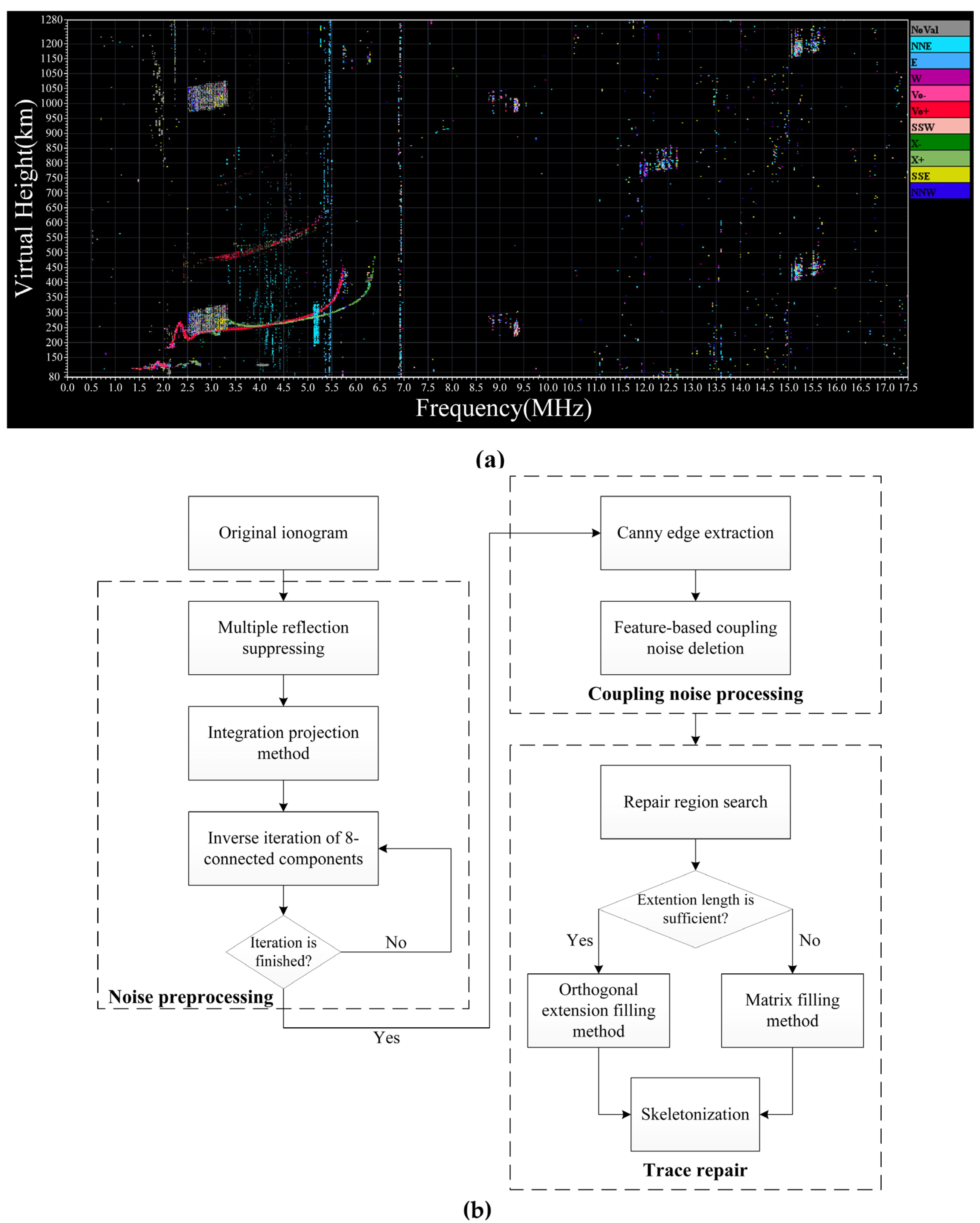
Figure 1. (a) The original ionogram obtained at 12:15 UT on 14 June 2021 by the ionosonde installed at Hainan. (b) The flowchart of the method described in this paper.
Atmosphere 15 00769 g001
Figure 2. Each step in the invalid signal suppression: (a) the binary original ionogram; (b) the image after median filtering and suppression; (c) the projection results with multiple interferences labeled by different colors; (d) the result of the invalid signal suppressing.
Atmosphere 15 00769 g002
Figure 3. Each step in the inverse iteration: (a) the image after the invalid signals suppression; (b) the image after the morphological processing; (c) the image after the inverse iteration.
Atmosphere 15 00769 g003
Figure 4. Each step in the Canny arithmetic edge extraction: (a) the original image before Canny; (b) the image after Gaussian filter and gradient processing; (c) the edge extraction result after weak edge elimination; (d) the result after the morphological closure operation and maximum 8-connected component extraction.
Atmosphere 15 00769 g004
Figure 5. The coupling noise removal by characteristic parameters. The red line is the O wave, the green line is the X wave, and the other color lines are the coupling noise.
Atmosphere 15 00769 g005
Figure 6. The diagram of two gap-filling methods: (a) the orthogonal extension diagram when |K| ≥ 1; (b) the orthogonal extension diagram when |K| < 1; (c) the orthogonal extension filling repair result; (d) the matrix filling repair result.
Atmosphere 15 00769 g006
Figure 7. Each step in trace repair: (a) the repair point search result of the separate O and X waves; (b) the combined trace repair result; (c) the skeletonization result extracted from the repaired image.
Atmosphere 15 00769 g007
Figure 8. Results of ionograms of different quality. The red line is the O wave, the green line is the X wave, and the other color lines are the noise.
Atmosphere 15 00769 g008
Table 1. The average statistical results of characteristic parameters of ionograms in Hainan.
SignalAverage PixelDispersion RateRetention Rate
NoVal5641.62.07558.86%
E2478.83.32568.60%
NNE3441.43.28237.58%
NNW1828.83.18095.58%
W1680.23.08337.08%
SSW1814.53.20056.23%
SSE1767.63.28459.01%
Vo+2369.62.112053.50%
Vo−623.82.774625.50%
X+1622.72.003862.36%
X−379.02.546335.54%
Disclaimer/Publisher’s Note: The statements, opinions and data contained in all publications are solely those of the individual author(s) and contributor(s) and not of MDPI and/or the editor(s). MDPI and/or the editor(s) disclaim responsibility for any injury to people or property resulting from any ideas, methods, instructions or products referred to in the content.