1. Introduction
Over the past few decades, industrial and population growth has led to the increase in atmospheric pollutants [
1,
2]. This has resulted in complaints and lawsuits from citizens about odour [
3,
4], typically emitted by agricultural, industrial, and waste management facilities, which tend to be built closer and closer to residential areas [
5].
Typically, a significant portion of environmental odour pollution often comes from diffuse sources [
6,
7]. In this context, one of the most challenging scenarios concerns the characterization of passive area sources, i.e., all those sources that typically do not have defined outlet airflow. Passive area sources are more difficult to deal with than active ones, because, due to the negligible outward airflow, their emission occurs “passively” by natural or forced convection, driven by the wind, from the liquid surface to the atmosphere [
8,
9,
10].
In other words, the wind is both responsible for the dispersion in the atmosphere and the driving force behind the emissive phenomenon. This fact complicates the study of odorous emission dispersion from such sources and has prompted researchers in this field to design devices capable of sampling the emission in the absence of a convective flow directly emitted by the source itself.
A sampling instrument for passive area sources must serve two key functions: firstly, it must act as a hood to isolate a specific portion of the surface within a known control volume. Secondly, it must create a controlled fluid dynamic environment that enables the establishment of a mass balance within the closed system. By sampling the outlet flow, this setup allows for the estimation of the specific emission rate.
Among the multitude of designs that have been developed historically for sampling instruments [
11], two different main families can be distinguished: the wind tunnel and the flux chamber. Within these two different sampling instruments, the behaviour, or rather the motion induced at the airflow, is very different. In the case of a wind tunnel, the airflow is theoretically one-way, plug-flow type, without vertical mixing [
12,
13]. It is commonly employed in Italy and Germany, for example, to sample passive area sources.
On the other hand, in the case of a flux chamber, adopted in the United States, the motion is as chaotic as possible as the inlet flux is well-mixed inside the hood, to keep the system as close as possible to the ideal state of perfect mixing [
14,
15,
16].
Despite the considerable differences that exist between the two types of instruments, the scientific community is not unanimous on the choice between one or the other. Even the regulations of different countries provide for different approaches [
17,
18,
19,
20]. Despite the absence of a universal approach, previous studies have highlighted that the choice between a wind tunnel and a flux chamber can result in significantly different estimates of emission rates [
21,
22,
23].
Furthermore, within the same family of devices (such as wind tunnels), various designs have been introduced, differing in aspects like geometry and operational conditions [
24,
25]. In the literature, several types of wind tunnels have been adopted for odour sampling. Early examples include those proposed by Lindvall [
26] and Lockyer [
27], later taken up by Sommer and Misselbrook [
12]; these are relatively voluminous portable hoods, with a sampling area of about 2 m length, 0.5–1 m width, 0.5 m height, and operating at speeds even greater than 1 m/s or attempting to approximate the wind speed measured at 30 cm height above the ground [
12]. Subsequently, several designs have been proposed to reduce size and thus improve portability. For instance, Smith [
28] proposed a more compact wind tunnel in which the dimensions of the sampling area are reduced to 0.25 m
2, with a height of 20 cm. Other examples of wind tunnels with reduced dimensions (length of 80 cm, width of 40 cm, height of 25 cm) and operating speeds below 1 m/s are those discussed by Jiang et al. [
29] and Schmidt and Bicudo [
30]. However, these velocities remain above 1 dm/s. This is a significant limitation because, as noted by Jiang et al. [
29], lower mean velocities generally result in improved aerodynamic performance. This has also been confirmed by Frechen et al. [
24], who emphasizes that operating at high speeds causes excessive dilution within the hood. Frechen et al. suggested a low-speed wind tunnel with dimensions of 1 m in length, 33 cm in width, and 12 cm in height, with velocities within the hood in the range of 0.01 and 0.03 m/s. Based on this, Capelli et al. [
25] designed a wind tunnel with the same effective height of 8 cm and a sampling area of 0.125 m
2, currently used in Italy for the sampling of passive area sources [
31]. This device is discussed in the present study to compare its performance with a new wind tunnel design.
In light of this, the present experimental study aims to evaluate the performance, in terms of fluid dynamics and mass transfer, of a wind tunnel recently developed by the Olfactometric Laboratory of Politecnico di Milano, which is proposed to have a more compact and handy design and a better flow distribution compared to the one proposed by Italian regulations in the field of odour [
25,
31].
The key innovations of this study include, first, its approach to evaluating the limitations of Italian wind tunnels. Unlike previous studies that relied on fluid dynamic modelling [
32,
33], this research is based on empirical experimental tests. Second, the study introduces a newly optimized wind tunnel design. This design is suggested to address the identified limitations of current standard devices, marking a significant advancement in wind tunnel technology.
2. Materials and Methods
2.1. Wind Tunnel Designs
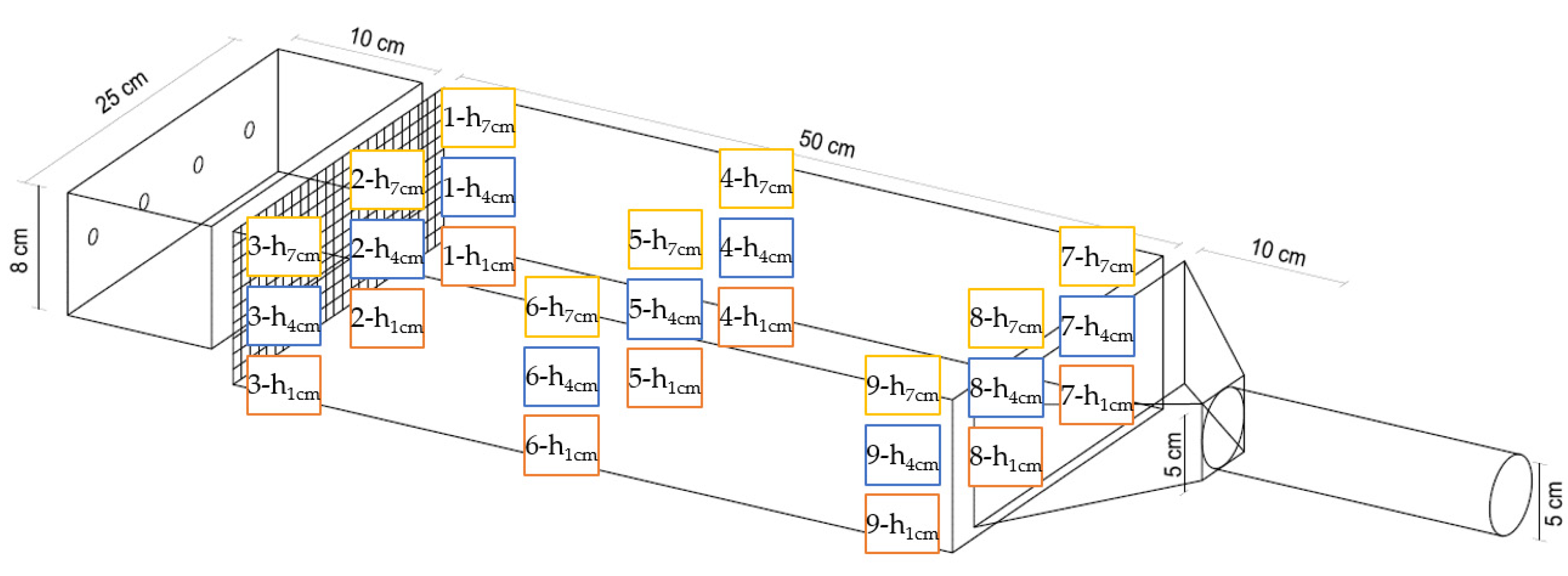
The sampling devices studied are the new wind tunnel developed by the Olfactometric Laboratory of Politecnico di Milano and the Italian regulatory sampling device (
Figure 1). The first one is a hood recently proposed to improve fluid dynamic performance and portability with respect to the Italian standard wind tunnel, discussed by Capelli et al. [
25].
The Italian standard wind tunnel (
Figure 1a) is composed of three main sections: an inlet section where the air is deflected into the central body through a divergent duct, the central part of the hood positioned directly above the emission source, and a final section, where the air is channelled through a convergent duct toward the outlet.
The divergent duct is designed with a section that increases horizontally while maintaining a constant vertical height. Inside, three flow deflectors create four vanes in which the air flows in homogenous parallel streams; at the entrance of the duct, a perforated grid promotes uniform airflow. The aim of this initial section is to establish a fully developed and homogeneous flow.
The central body is a rectangular parallelepiped 8 cm high, 50 cm long, and 25 cm wide, with a total sampling area of 1250 cm2. The mass transfer phenomenon occurs in this section of the wind tunnel: considering that the central body of the sampling device is open, the hood is placed over the emission source to be sampled, enabling the airflow passing through the device.
The convergent duct is designed with a decreasing horizontal section, while the vertical dimension remains consistent with the height of the central body and the inlet duct. This section facilitates the conveyance of air enriched with the stripped VOCs (i.e., volatile organic compounds), thus enabling sampling at the outlet.
The new proposed wind tunnel (
Figure 1b), whose new design is derived from the current Italian standard one, is still divided into three main sections: inlet, central body, and outlet.
An inlet section designed to homogenize the flow, as an alternative for the divergent duct, consists of a chamber with a length of 10 cm and a height of 8 cm. The inlet air stream enters through four 10 mm diameter openings, which serve to better distribute the incoming flow in the wind tunnel, and passes through a perforated plate positioned between this section and the central body, introduced to promote flow uniformity in the output from the initial section entering the central body. As will be discussed in
Section 2.2.2, the initial section will be optimized (e.g., by introducing fillers) to promote the homogenization of the incoming flow.
The central body shares the same dimensions and function as the previously described wind tunnel.
The outlet section consists of a 10 cm long convergent section, followed by a cylindrical outlet duct with a diameter of 5 cm filled with 15 mm random polypropylene filling.
This alternative design of the outlet section of the hood, compared to the Italian standard wind tunnel, is expected to enhance the mixing of the gaseous airflow. In addition, the presence of the fillers, due to their pressure drop, may increase the pressure inside the hood, and can help to prevent the infiltration of external air.
It is worth noting that the hood is tested before and after the insertion of the fillers to ensure that the introduction of the fillers does not interfere with the system by generating additional odours. This testing is performed in accordance with the requirements outlined in the European standard for dynamic olfactometry [
34], to assess the background odour concentration of materials used.
2.2. Fluid Dynamic Tests: Experimental Setup
2.2.1. Italian Standard Wind Tunnel and New Proposed Wind Tunnel Design
To investigate the fluid dynamic behaviour of the two wind tunnels, i.e., the Italian standard wind tunnel and the new proposed wind tunnel design, described in the previous section (
Figure 1), a suitable experimental setup was designed. The central body of the hoods is placed over a plexiglass sheet to simulate the presence of the liquid level, as in the case of real field sampling. The plexiglass sheet is perforated in nine points to allow for the insertion of an anemometer: three holes at the beginning, three in the middle, and three at the end; each hole along the perimeter is positioned 2.5 cm away from the edges.
The air velocity in the central body of the wind tunnel is measured at 27 points: for each of the nine holes, three different heights above the plexiglass sheet are considered, i.e., 1 cm, 4 cm, and 7 cm. An example can be seen in
Figure 2.
This approach enables a comprehensive analysis of the flow within the central body of the wind tunnel, examining the fluid dynamics near the walls and corners, as well as in the centre of the hood.
Velocity measurements last two minutes: this time frame appears to be adequate to observe the velocity trend, as fluctuations around the average value remain relatively stable within the selected interval. Measurements are carried out using a Testo 440 multifunctional tool in combination with a Testo hot sphere probe. This instrument has a measuring range of 0–10 m/s and an accuracy of ±(0.03 m/s + 5% of the measured value), with a sampling frequency of one data point per second.
The inlet airflow is regulated to 2500 sL/h (0 °C, 1 atm), which is the typical flow rate used for field sampling [
35].
2.2.2. New Proposed Wind Tunnel Design: Optimized Configurations
After a preliminary evaluation to optimize the configuration of the inlet air supply system (i.e., the system of tubes and fittings at the chamber entrance) to ensure that the airflow is not affected by the inclination of the inlet tubes, the fluid dynamic measurements are repeated for different inlet section configurations, as shown in
Table 1. These configurations are designed to enhance the performance of the new wind tunnel, starting from the initial setup (
Figure 1b; Conf. 1 in
Table 1).
Each alternative configuration is designed to overcome the limitations of the previous ones and to establish the best currently available setup.
In particular, compared to the original configuration tested, the modifications involve the following:
The dimensions of the holes of the perforated plate;
The fittings after the four inlet 10 mm diameter openings;
The presence of filling bodies in the inlet chamber;
A grid as an alternative to the perforated plate.
First, some evaluations related to the perforated plates are carried out by testing three configurations with different diameter holes, i.e., 10 mm (Conf. 1), 5 mm (Conf. 2), and 3 mm (Conf. 3).
To increase the pressure drops and regulate the inlet airflow, alternative configurations of fittings directed upwards (Conf. 4) or downwards (Conf. 5) are investigated.
As an alternative, to increase pressure drops and improve flow distribution, the inlet chamber is filled with 15 mm (Conf. 6) or 25 mm (Conf. 7) random polypropylene fillers.
Conf. 8 considers the best combination of perforated plate, fittings, and filling bodies previously identified, to further increase the pressure drop and combine the advantages of the previous configurations.
Finally, a 10 mm mesh grid (Conf. 9) is investigated as a potential alternative to the perforated plate, in order to promote a more homogeneous airflow.
2.3. Pressure Tests: Experimental Setup
An additional assessment involves measuring the overpressure within both wind tunnels. This measurement is essential, as excessively high pressure inside the hood can alter the vapour–liquid equilibrium condition.
First of all, it should be noted that the sampling devices under investigation include the new proposed wind tunnel, optimized on the basis of fluid dynamics tests, i.e., Conf. 9, and the Italian standard design, both operating with an airflow of 2500 sL/h. The sampling hoods are placed over a basin 52 cm in length, 36 cm in width, and 16 cm in height, filled with 26 L of water.
Two 10 mm diameter tubes are connected to the MRU OPTIMA7. This instrument has a measuring range of ±300 hPa, an absolute accuracy of 0.02 hPa, and a resolution of 0.01 hPa.
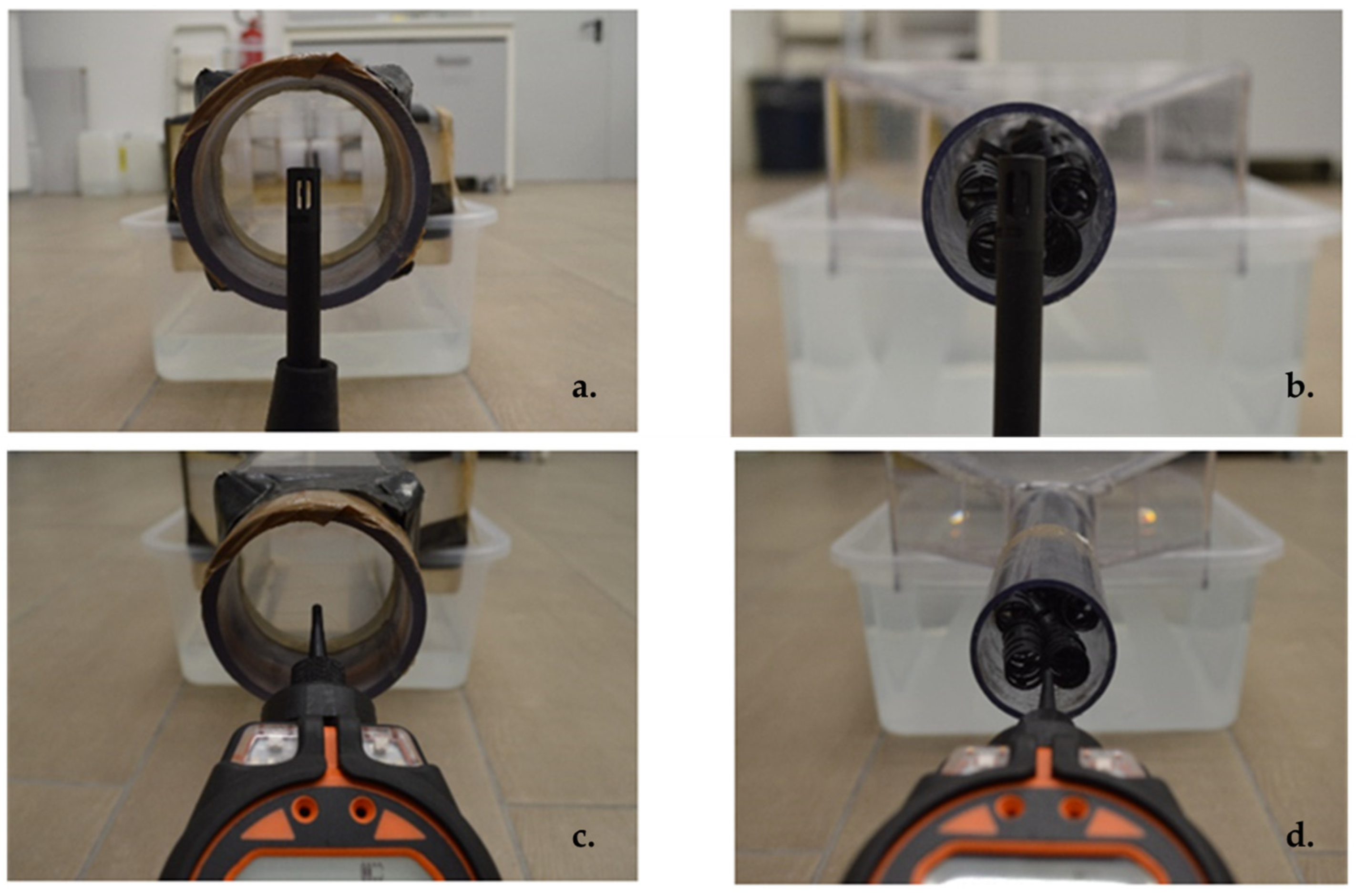
To estimate the overpressure inside the sampling devices (
Figure 3), one of the tubes connected to the MRU OPTIMA7 is fixed inside the central body of the hood, while the other one is left exposed to atmospheric air.
2.4. Mass Transfer Tests: Experimental Setup
In order to verify the absence of a vertical concentration gradient at the outlet of the two wind tunnel devices, and thus ensure the representativeness of the sample collected, pure water and an aqueous solution of 2-butanone, i.e., Methyl Ethyl-Ketone (MEK), which is a typical tracer for experiments [
36,
37], are tested. MEK is chosen also because of its vapour pressure value at room temperature (i.e., 10.5 kPa at 20 °C) and mainly because the expected concentration, based on theoretical models available in the literature [
38,
39,
40], falls within the detection range of the instrument.
To perform the experimental measurement, the wind tunnels, i.e., the optimized new design (Conf. 9) and the Italian standard one, are placed above a basin 52 cm long, 36 cm wide, and 16 cm high, filled with 26 L of liquid. An airflow of 2500 sL/h is blown into the hoods.
The water concentration in the air, expressed as relative humidity, is measured both at the inlet and the outlet. The former is carried out by inserting the Testo hygrometer 605i in the inlet tube through a glass T-connector. The latter is carried out by positioning the measuring device at three different heights of the outlet duct of the new proposed wind tunnel, i.e., 0 cm, 2.5 cm, and 5 cm from the bottom, while for the Italian standard wind tunnel (
Figure 4) five heights are considered, i.e., 0 cm, 2 cm, 4 cm, 6 cm, and 8 cm from the bottom. The reason for this is that the wider outlet of this hood, i.e., 8 cm diameter, allows more points to be sampled compared to the novel device, i.e., the 5 cm diameter.
The instrument used, a Testo 605i hygrometer, has a measuring range of 0 to 100%, a resolution of 0.1%, and an accuracy (at 25 °C) of ±3.0% when the relative humidity is between 10 and 35%, ±2.0% when it is between 35 and 65%, ±3.0% when it is between 65 and 90%, and ±5% when it is <10% or >90%.
In the case of VOC aqueous solution, the experimental setup (
Figure 4) is the same as described for the pure water test. However, in this case, the solution consists of 13 g of MEK dissolved in 26 L of solution, which means an initial concentration of the VOC in the liquid phase of 0.5 g/L.
Since the VOC concentration in the inlet airflow is zero, measurements are conducted similarly to those for water, but only at the hood outlet, after the mass transfer phenomenon has occurred and the air has been enriched with VOCs (
Figure 4).
The instrument used to assess the outlet concentration is the Tiger VOC gas detector, a portable PID instrument for the rapid and accurate detection of volatile organic compounds.
It facilitates the measurement of chemical concentrations for continuous monitoring, allowing for the assessment of the stability of the readings over time.
It provides a detection range of 0 to 20,000 parts per million (ppm), with a minimum sensitivity of 0.001 ppm (1 ppb). The PID is calibrated using isobutylene, so the value reported by the instrument is adjusted with a Response Factor (RF) to convert the isobutylene calibrated measurement to a concentration of the target volatile.
3. Results and Discussion
3.1. Fluid Dynamic Analysis
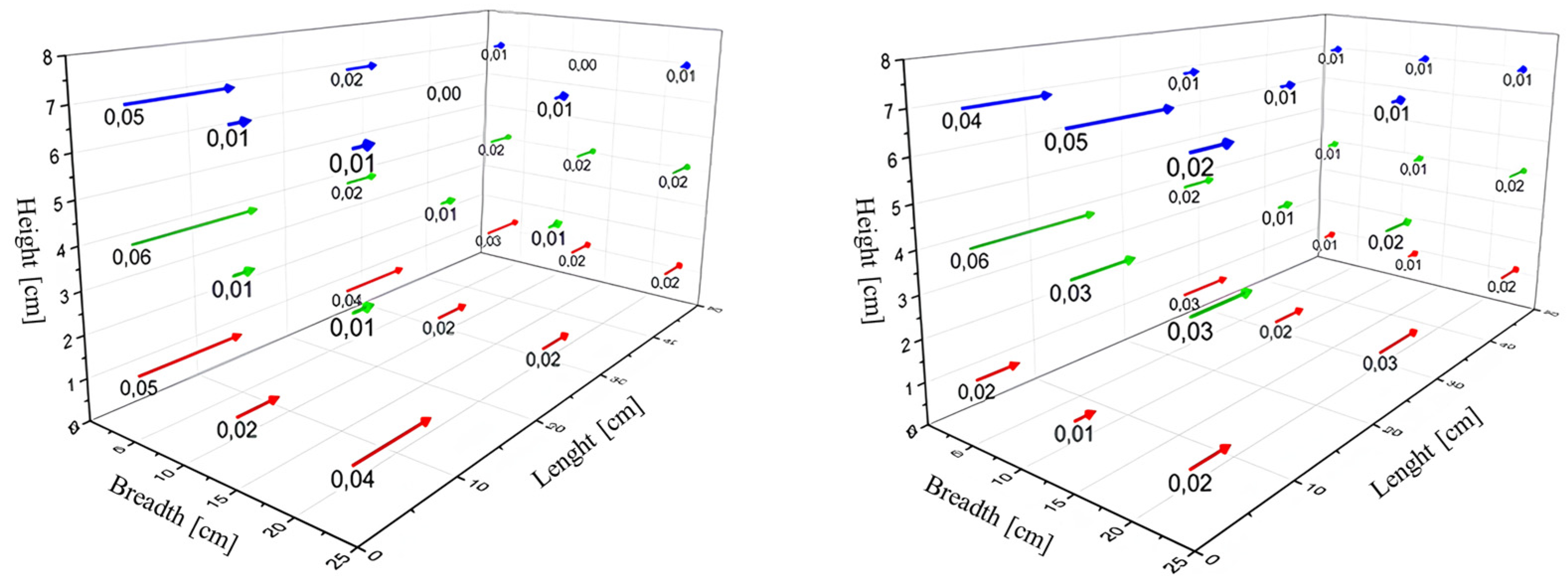
The results of the fluid dynamic tests conducted in the central body of the wind tunnels are shown in
Figure 5, following the layout in
Figure 2. These results represent the time-averaged values over the two-minute measurement period. For the sake of brevity, only the results for the final optimized configuration (Conf. 9) are provided for the new wind tunnel design. Results for the other configurations, and the standard deviations of each velocity measurement, are available in the
Supplementary Material.
The three measurement heights are highlighted in different colours: in red the height of 1 cm, in green the height of 4 cm, in blue the height of 7 cm. The direction of the arrows represents the airflow within the central body of the hood, while the magnitude indicates the speed measured during the various tests.
It is important to note that the accuracy of the instrument is ±0.03 m/s, comparable to the expected theoretical value in the central body:
where the following holds:
WT subscript refers to Wind Tunnel.
Qair [m3/s] is the air flowrate, i.e., 2500 sL/h.
HWT [m] is the height of the central body of the wind tunnel, i.e., 0.08 m.
BWT [m] is the breadth of the central body of the wind tunnel, i.e., 0.25 m.
Therefore, measured velocities in the range of approximately 0.01 m/s and 0.06 m/s can be considered acceptable.
The velocities recorded for the Italian standard wind tunnel are within the acceptable range (
Figure 5); nonetheless, the presence of a preferential airflow channel can be observed: this phenomenon is evident at position 1 (
Figure 2), i.e., the inlet of the central body on the left, where the velocities are higher (around 0.06 m/s) compared to other points. This behaviour could be attributed to a not completely homogeneous distribution of air in the four channels present in the divergent part of the hood.
Concerning the newly proposed wind tunnel design, the initial tested configurations (Conf. 1–8) demonstrated a non-uniform distribution of flow within the wind tunnel, particularly along the length of the hood, with higher velocities observed at the entrance of the central body.
This behaviour may be due to the discontinuity caused by air passing through the small holes in the perforated plate, which generates vortices and greater fluctuations in the initial zone and increases the velocity recorded by the hot-wire anemometer. This phenomenon is progressively damped along the hood, as it moves away from the perforated plate.
By incorporating the 10 mm mesh grid (Conf. 9), the velocities at each point along the hood fall within the acceptable range and show a fairly uniform flow distribution, as shown in
Figure 5.
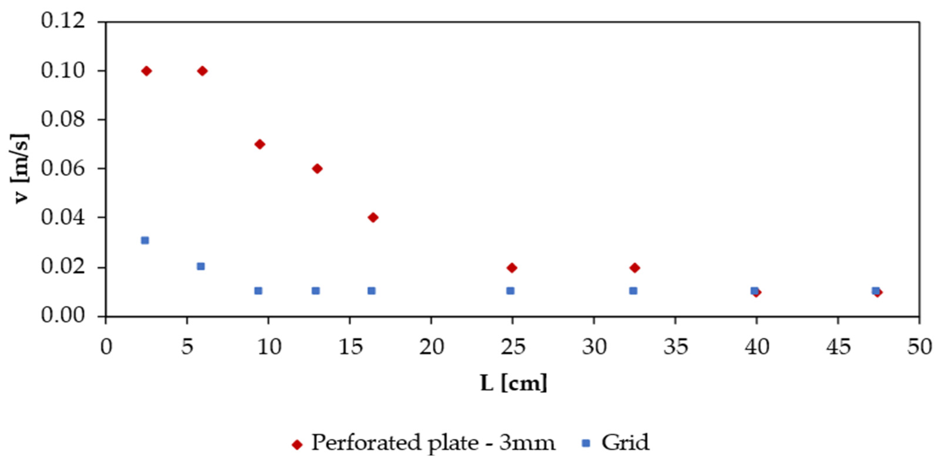
Indeed, it can be observed that in Conf. 8, with the perforated plate, the expected theoretical value of velocity is achieved approximately 16.5 cm from the entrance of the central body, i.e., roughly one-third of the length of the central body of the hood, as demonstrated by
Figure 6. In contrast, in the case of the grid (Conf. 9), these velocities are already detected 2.5 cm from the inlet of the central body, confirming the effectiveness associated with the introduction of the grid.
It is worth highlighting that the velocities reported in
Figure 6 refer to tests in which the plexiglass sheet is specifically perforated at nine points along the entire length of the central body. The measurements refer to a height of 4 cm (half the height of the central body) and last for two minutes. This type of test is conducted only for Conf. 8 and Conf. 9 to illustrate how the inclusion of the grid ensured the achievement of a homogeneous condition right from the inlet of the central body.
Comparing the Italian standard wind tunnel with the best configuration for the new one, i.e., the combination of downward-facing fittings, 15 mm filling bodies, and a 10 mm mesh grid, both hoods appear acceptable from a fluid dynamic point of view; however, the new wind tunnel design exhibits a slightly more homogenous and uniform velocity distribution and does not have the issue of the preferential channel.
3.2. Pressure Analysis
The results of the pressure measurements, i.e., the overpressure inside the two hoods, revealed an estimated overpressure of 0.1 Pa for the Italian standard WT. For the new proposed wind tunnel design, the presence of fittings and fillers increases this value to 5 Pa.
Given the magnitude of these overpressures, which remain significantly below atmospheric pressure, experiments have confirmed that they do not result in excessive pressure increases. Indeed, a substantial overpressure relative to the external environment could potentially disrupt the equilibrium conditions at the gas–liquid interface inside the hood, thereby affecting the mass transfer phenomenon between the fluid in the basin and the incoming air in the hood’s central body.
Conversely, the slight overpressure measured for the new proposed design appears advantageous in preventing the infiltration of external air.
3.3. Mass Transfer Analysis
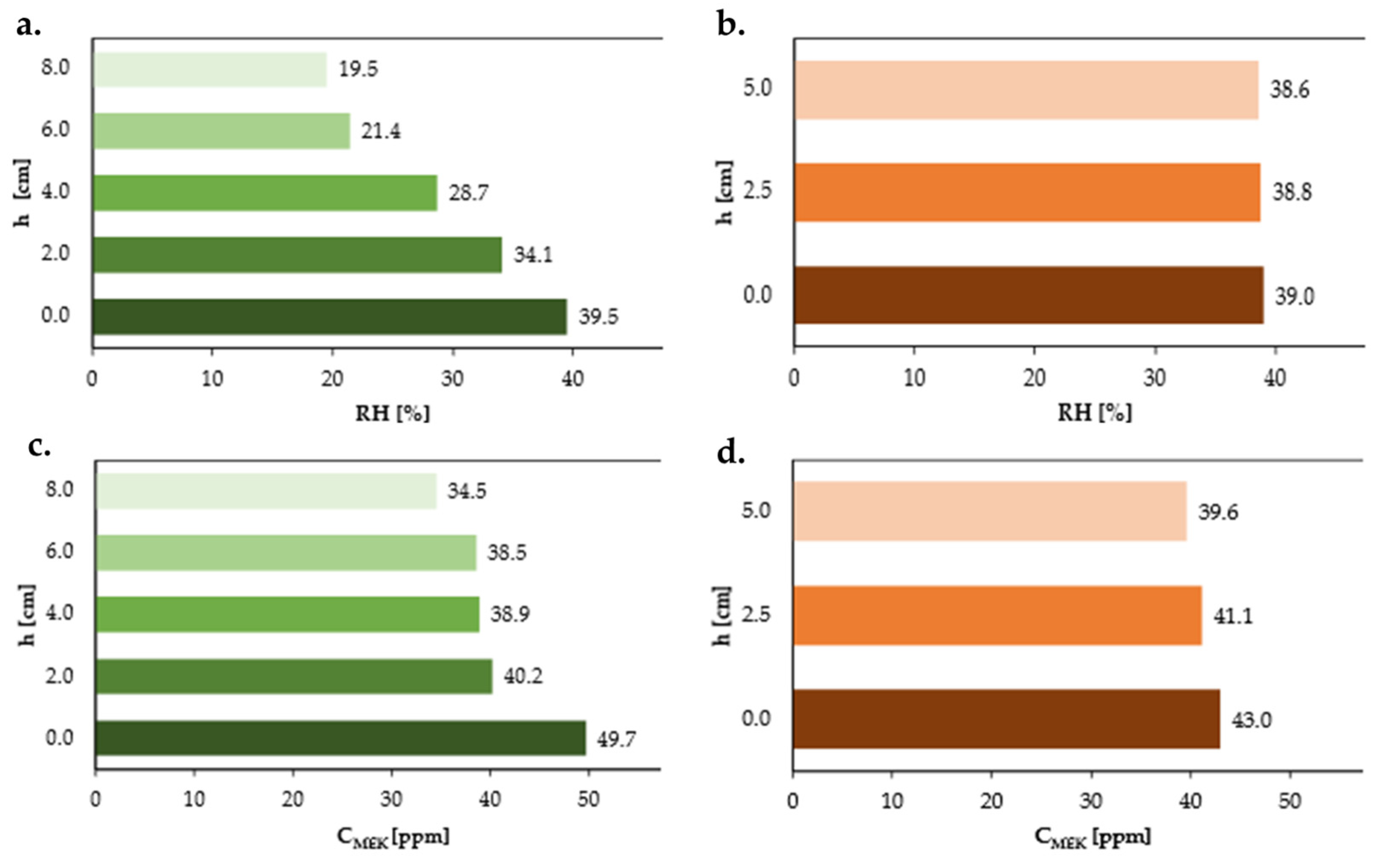
Focusing on the pure water mass transfer tests, for the relative humidity results at the outlet section of the hoods,
Figure 7 shows, for the Italian standard wind tunnel, not homogeneous values moving along the vertical direction, but a decrease in relative humidity, from 39.5% to 19.5%, moving upwards in the exit duct. This poses a potential problem because the convergent section does not provide sufficient homogenization to equalize the outlet concentration. As a result, different concentrations are observed depending on the height at which the gaseous sample is collected from the exit section.
On the other hand, for the new wind tunnel, concentration values appear uniform throughout the height of the outlet section. This homogenization is ascribable to the presence of fillers in the outlet duct, which ensure an adequate mixing.
The results obtained for the aqueous MEK solution (
Figure 7) confirm the findings discussed in the case of water:
Figure 7 illustrates that, once more, although less pronounced, a decreasing trend in concentration can be observed in the Italian standard wind tunnel along the vertical direction, moving upwards in the outlet duct. Conversely, the measurements in the new proposed wind tunnel are essentially constant.
Therefore, in terms of the homogenization of the outlet flow, it can be concluded that the new proposed wind tunnel performances are significantly better compared to the Italian standard one, ensuring uniform outlet concentrations throughout the height of the outlet duct.
4. Conclusions
The present experimental study discusses an optimization study of a new wind tunnel design, developed by the Olfactometric Laboratory of Politecnico di Milano, addressing fluid dynamics, pressure, and mass transfer analysis.
It has been demonstrated that the new proposed wind tunnel design outperforms the Italian standard one in various aspects. Indeed, according to the results of the fluid dynamic tests, the preferential channel issue that exists in the Italian standard wind tunnel is resolved as a result of a more uniform velocity distribution within the central body of the new proposed design hood. The pressure tests reveal that the presence of fillers in the outlet duct and inlet chamber of the new wind tunnel does not significantly alter the pressure inside the hood; actually, the slight overpressure may help in preventing the infiltration of external air.
Moreover, the results of the mass transfer tests show that a major limitation in the Italian standard wind tunnel is the presence of a concentration gradient along the vertical direction of the outlet duct, highlighting concentration values that differ up to a factor of two depending on the point where the measurement is taken. The new proposed wind tunnel design has almost totally solved this issue thanks to the filling bodies that play a key role in achieving complete mixing at the outlet.
Finally, it also ensures a more compact design and reduced weight, making it more convenient and portable for field sampling.
This study presents notable innovations while recognizing that certain aspects could be integrated or improved in future work. In particular, the low flow velocities within the wind tunnel introduce challenges for fluid dynamic measurements, necessitating the use of high-resolution and accurate instruments. In this context, the hot-wire anemometer is chosen for its suitability, offering superior performance and compact size compared to other instruments, although its accuracy is comparable to the low measured velocities.
Overall, addressing these challenges in future studies will be essential for optimizing measurements within the wind tunnel environment.
A potential direction for further research could involve the use of CFD simulations to validate the experimental results: the approach discussed in this study allows for the establishment of a solid foundation based on empirical data, which can later be complemented by computational models to further validate these findings.
In addition, to further optimize the design of the new wind tunnel, it might be useful to extend the inlet section after the grid (
Figure 8), before the entrance of the central body, even though the grid has already almost completely solved the inlet discontinuity problem (caused by the airflow passing through the small holes of the perforated plate).
This new configuration should further improve the fluid dynamics within the hood to achieve a fully developed and homogeneous flow throughout the entire central body, eliminating any discontinuity problem in the central body’s inlet.

