

Non-Line-of-Sight Atmospheric Optical Communication in the Visible Wavelength Range between UAV and the Ground Surface


Abstract
:1. Introduction
- (1)
- (2)
- (3)
- (4)
- (5)
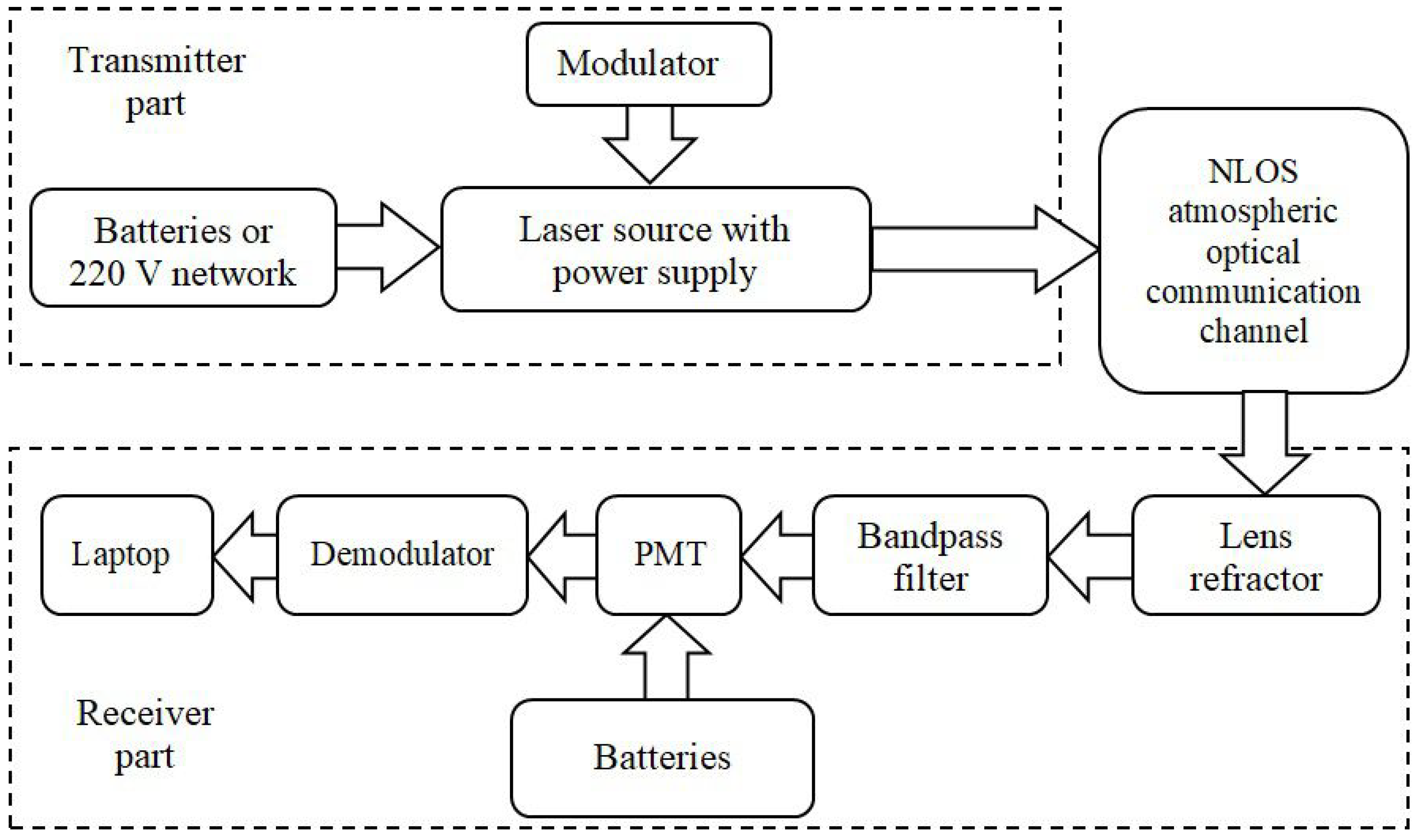
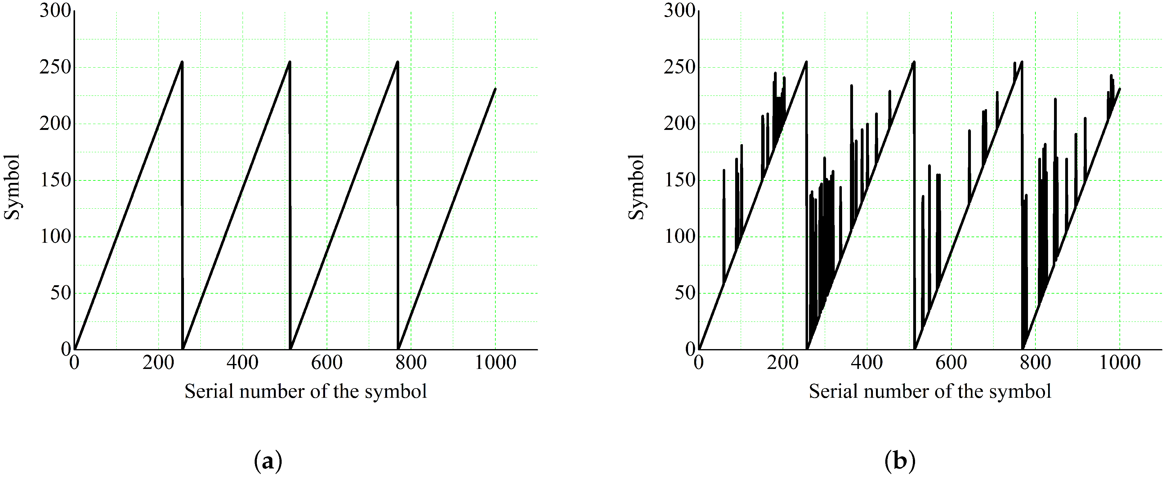
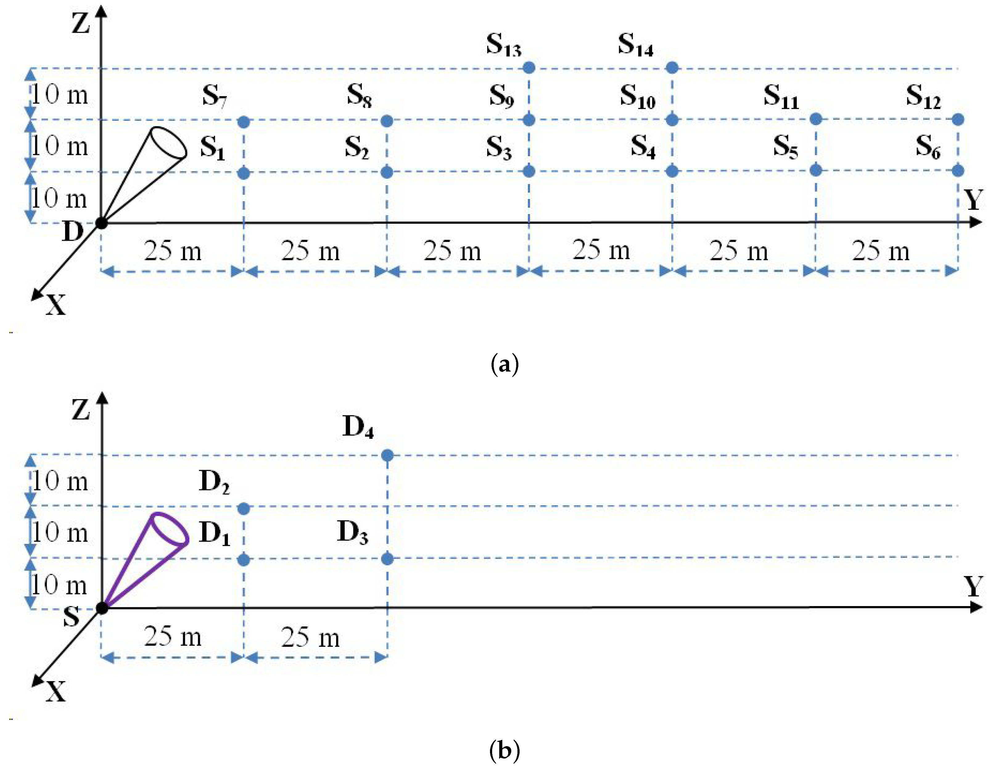
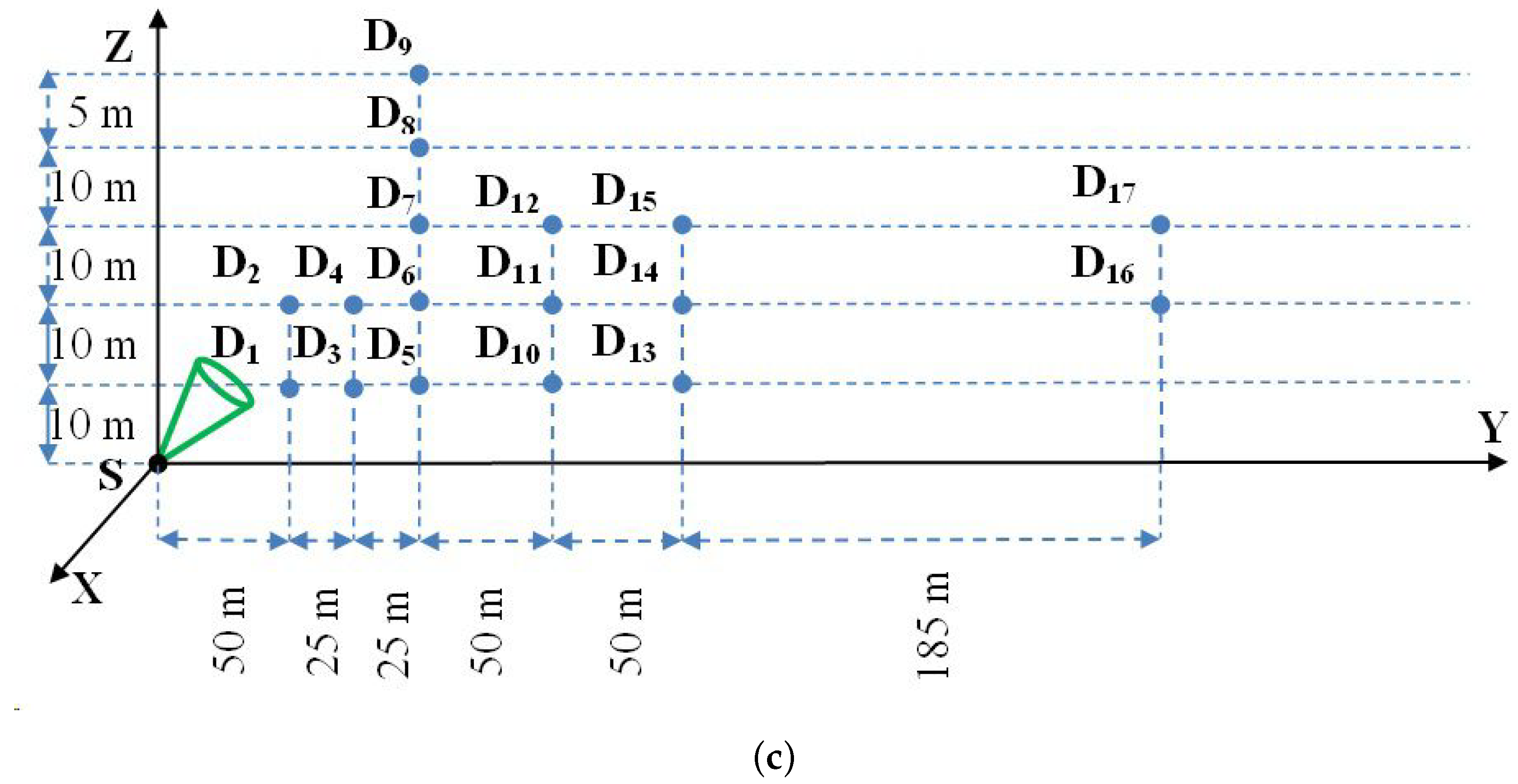
2. Investigation Methodology
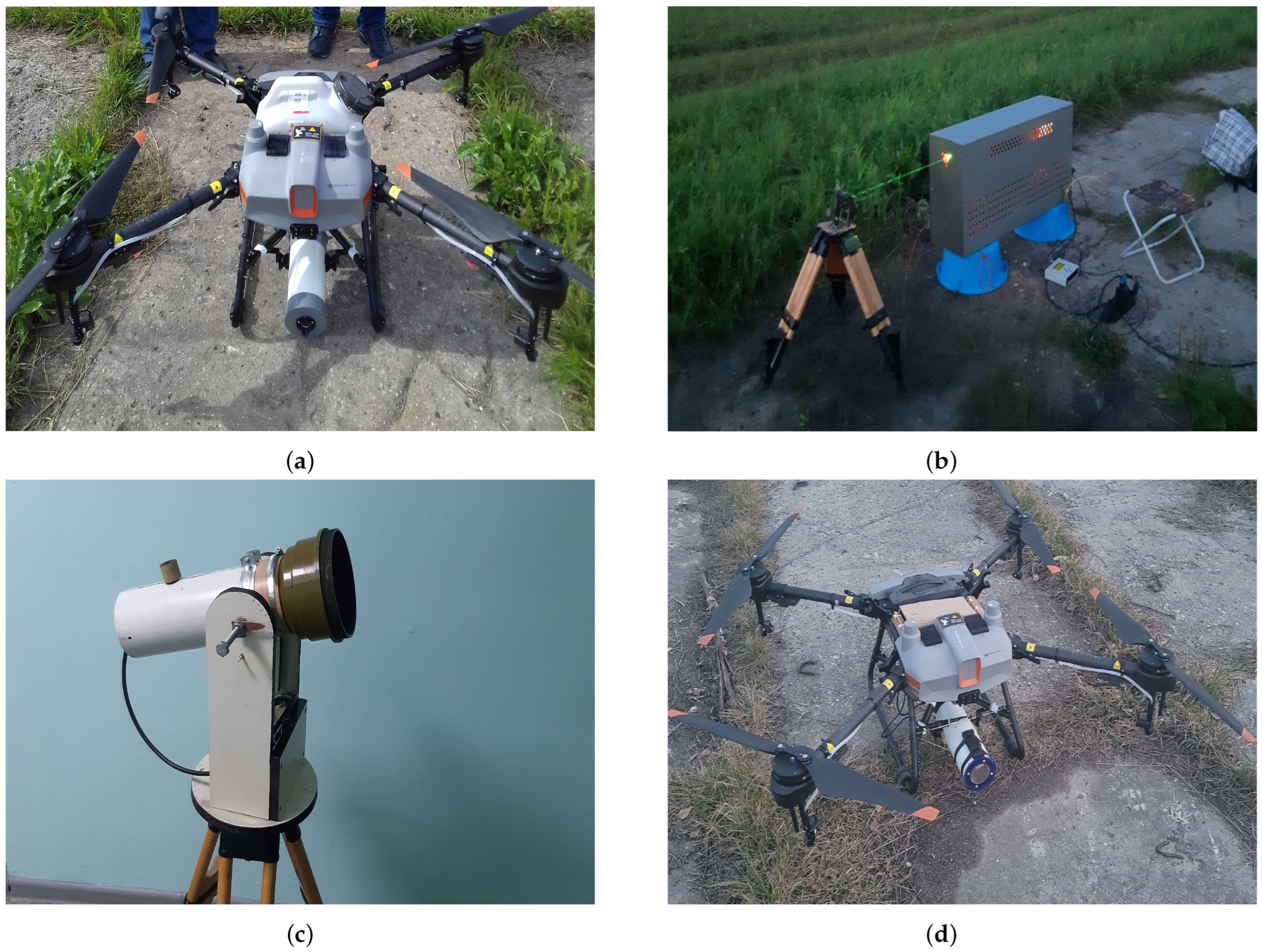
3. Experimental Setup
4. Result and Discussions
5. Conclusions
- (1)
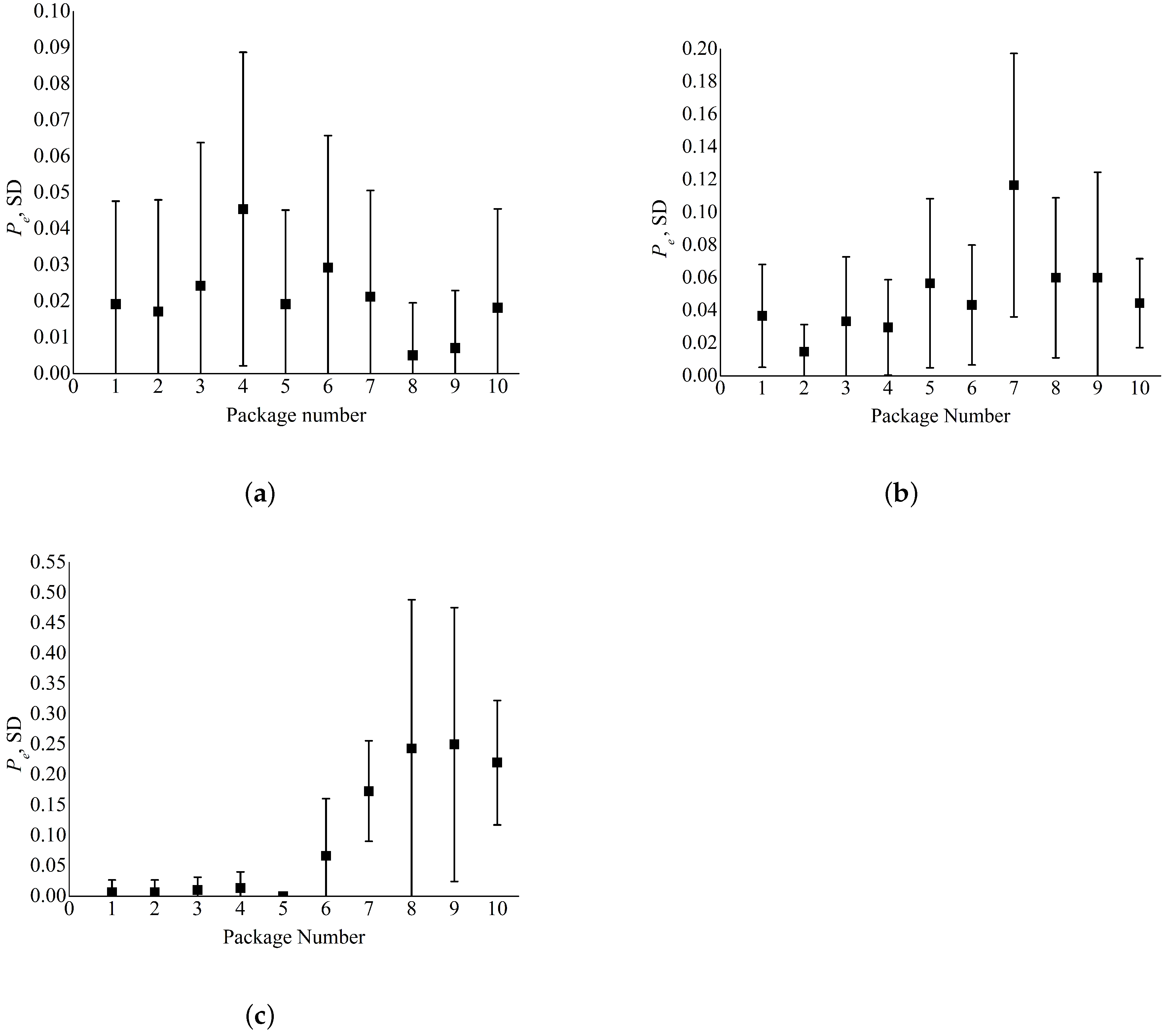
- With the developed transceiver system at a wavelength of = 450 nm for the UAV–ground scheme, the maximum baseline distance of stable communication at a UAV height of = 10 m was = 150 m with an SER of 0.22. At = 20 m, the maximum range of stable communication was = 125 m with an SER of 0.23. At a height of = 30 m, we failed to establish a stable communication in experimental series 1.
- (2)
- The use of the developed transceiver system at a wavelength of = 450 nm allowed a stable communication by the ground–UAV scheme to be organized only for a baseline distance of = 50 m and a UAV height up to = 30 m.
- (3)
- The use of the developed NLOS communication system at a wavelength of = 510 nm by the ground–UAV scheme allowed a stable communication to be organized at UAV heights up to = 45 m and baseline distances up to 100 m. At baseline distances of 150 385 m, the NLOS communication was stable at 20 m. The maximum baseline distance of stable communication for this transceiver system was 385 m.
Author Contributions
Funding
Institutional Review Board Statement
Informed Consent Statement
Data Availability Statement
Conflicts of Interest
References
- Wang, C.X.; Huang, J.; Wang, H.; Gao, X.; You, X.; Hao, Y. 6G Wireless Channel Measurements and Models: Trends and Challenges. IEEE Veh. Technol. Mag. 2020, 15, 22–32. [Google Scholar] [CrossRef]
- Ding, J.; Mei, H.; I, C.-L.; Zhang, H.; Liu, W. Frontier Progress of Unmanned Aerial Vehicles Optical Wireless Technologies. Sensors 2020, 20, 5476. [Google Scholar] [CrossRef] [PubMed]
- Kong, H.; Lin, M.; Zhang, J.; Ouyang, J.; Zhu, W.P.; Alouini, M.-S. Beamforming Design and Performance Analysis for Satellite and UAV Integrated Networks in IoRT Applications. IEEE Internet Things J. 2022, 9, 14965–14977. [Google Scholar] [CrossRef]
- Qu, L.; Xu, G.; Zeng, Z.; Zhang, N.; Zhang, Q. UAV-Assisted RF/FSO Relay System for Space-Air-Ground Integrated Network: A Performance Analysis. IEEE Trans. Wirel. Commun. 2022, 21, 6211–6225. [Google Scholar] [CrossRef]
- Li, M.; Hong, Y.; Zeng, C.; Song, Y.; Zhang, X. Investigation on the UAV-To-Satellite Optical Communication Systems. IEEE J. Sel. Areas Commun. 2018, 36, 2128–2138. [Google Scholar] [CrossRef]
- Mondal, A.; Hossain, A. Channel characterization and performance analysis of unmanned aerial vehicle-operated communication system with multihop radio frequency–free-space optical link in dynamic environment. Int. J. Commun. Syst. 2020, 33, e4568. [Google Scholar] [CrossRef]
- Ajam, H.; Najafi, M.; Jamali, V.; Schober, R. Ergodic Sum Rate Analysis of UAV-Based Relay Networks With Mixed RF-FSO Channels. IEEE Open J. Commun. Soc. 2020, 99, 72–85. [Google Scholar] [CrossRef]
- Agheli, P.; Beyranvand, H.; Emadi, M.J. UAV-Assisted Underwater Sensor Networks Using RF and Optical Wireless Links. J. Light. Technol. 2021, 39, 7070–7082. [Google Scholar] [CrossRef]
- Singh, P.; Bohara, V.A.; Srivastava, A. On the Optimization of Integrated Terrestrial-Air-Underwater Architecture Using Optical Wireless Communication for Future 6G Network. IEEE Photonics J. 2022, 14, 7355712. [Google Scholar] [CrossRef]
- Zhao, T.; Zhao, Y.; Liu, K. Wireless ultraviolet cooperative unmanned aerial vehicle formation communication link maintenance method. Appl. Opt. 2022, 61, 7140–7149. [Google Scholar] [CrossRef]
- Singh, D.; Swaminathan, R. Comprehensive Performance Analysis of Hovering UAV-Based FSO Communication System. IEEE Photonics J. 2022, 14, 1–13. [Google Scholar] [CrossRef]
- Ghanbari, M.; Ataee, M.; Sadough, S.M.S. Outage Performance Analysis for UAV-Based Mixed Underwater-FSO Communication Under Pointing Errors. In Proceedings of the 4th West Asian Symposium on Optical and Millimeter-Wave Wireless Communications (WASOWC), Tabriz, Iran, 12–13 May 2022; pp. 1–5. [Google Scholar] [CrossRef]
- Park, S.; Yeo, C.I.; Heo, Y.S.; Ryu, J.H.; Kang, H.S.; Lee, D.-S.; Jang, J.-H. Tracking Efficiency Improvement According to Incident Beam Size in QPD-Based PAT System for Common Path-Based Full-Duplex FSO Terminals. Sensors 2022, 22, 7770. [Google Scholar] [CrossRef] [PubMed]
- Dabiri, M.T.; Rezaee, M.; Mohammadi, L.; Javaherian, F.; Yazdanian, V.; Hasna, M.O.; Uysal, M. Modulating Retroreflector Based Free Space Optical Link for UAV-to-Ground Communications. IEEE Trans. Wirel. Commun. 2022, 21, 8631–8645. [Google Scholar] [CrossRef]
- Fawaz, W.; Abou-Rjeily, C.; Assi, C. UAV-Aided Cooperation for FSO Communication Systems. IEEE Commun. Mag. 2018, 56, 70–75. [Google Scholar] [CrossRef]
- Weisman, M.J.; Dagefu, F.T.; Moore, T.J.; Arslan, C.H.; Drost, R.J. Analysis of the low-probability-of-detection characteristics of ultraviolet communications. Opt. Express 2020, 28, 23640–23651. [Google Scholar] [CrossRef]
- Becker, D.; Fiebig, U.-C.; Schalk, L. Wideband Channel Measurements and First Findings for Low Altitude Drone-to-Drone Links in an Urban Scenario. In Proceedings of the 14th European Conference on Antennas and Propagation (EuCAP), Copenhagen, Denmark, 15–20 March 2020; pp. 1–5. [Google Scholar] [CrossRef]
- Zhao, T.; Yu, X.; Liu, P.; Liu, L. Ultraviolet anti-collision and localization algorithm in UAV formation network. Optik 2019, 192, 162919. [Google Scholar] [CrossRef]
- Tadayyoni, H.; Ardakani, M.H.; Heidarpour, A.R.; Uysal, M. Ultraviolet Communications for Unmanned Aerial Vehicle Networks. IEEE Wirel. Commun. Lett. 2022, 11, 178–182. [Google Scholar] [CrossRef]
- Tadayyoni, H.; Uysal, M. Ultraviolet Communications for Ground-to-Air Links. In Proceedings of the 27th Signal Processing and Communications Applications Conference (SIU), Sivas, Turkey, 24–26 April 2019; pp. 1–4. [Google Scholar] [CrossRef]
- Zhao, T.; Xie, Y.; Xu, S.; Wang, J.; Wang, H. Flocking of UAV Formation with Wireless Ultraviolet Communication. Wirel. Pers. Commun. Int. J. 2020, 114, 2551–2568. [Google Scholar] [CrossRef]
- Sunstein, D.E. A Scatter Communications Link at Ultraviolet Frequencies. Bachelor’s Thesis, Department of Electrical Engineering, Massachusetts Institute of Technology, Cambridge, MA, USA, 1968. Available online: http://hdl.handle.net/1721.1/13670 (accessed on 14 November 2023).
- Harvey, G.L. A Survey of Ultraviolet Communication Systems; Naval Research Laboratory Technical Report; Naval Research Laboratory: Washington, DC, USA, 1964. [Google Scholar]
- Vavoulas, A.; Sandalidis, H.G.; Chatzidiamantis, N.D.; Xu, Z.; Karagiannidis, G.K. A Survey on Ultraviolet C-Band (UV-C) Communications. IEEE Commun. Surv. Tutor. 2019, 21, 2111–2133. [Google Scholar] [CrossRef]
- Ding, H.; Chen, G.; Majumdar, A.K.; Sadler, B.M.; Xu, Z. Modeling of non-line-of-sight ultraviolet scattering channels for communication. IEEE J. Sel. Areas Commun. 2009, 27, 1535–1544. [Google Scholar] [CrossRef]
- Drost, R.J.; Sadler, B.M. Survey of ultraviolet non-line-of-sight communications. Semicond. Sci. Technol. 2014, 29, 11. [Google Scholar] [CrossRef]
- Elshimy, M.A.; Hranilovic, S. Non-line-of-sight single-scatter propagation model for noncoplanar geometries. J. Opt. Soc. Am. A 2011, 28, 420–428. [Google Scholar] [CrossRef] [PubMed]
- Chen, G.; Xu, Z.; Ding, H.; Sadler, B.M. Path loss modeling and performance trade-off study for short-range non-line-of-sight ultraviolet communications. Opt. Express 2009, 17, 3929–3940. [Google Scholar] [CrossRef] [PubMed]
- Xu, C.; Zhang, H. Packet error rate analysis of IM/DD systems for ultraviolet scattering communications. In Proceedings of the MILCOM 2015—2015 IEEE Military Communications Conference, Tampa, FL, USA, 26–28 October 2015; pp. 1188–1193. [Google Scholar]
- Liao, L.; Li, Z.; Lang, T.; Chen, G. UV LED array based NLOS UV turbulence channel modeling and experimental verification. Opt. Express 2015, 23, 21825–21835. [Google Scholar] [CrossRef] [PubMed]
- Tarasenkov, M.V.; Belov, V.V.; Poznakharev, E.S. Estimation of optimal wavelengths for atmospheric non-line-of-sight optical communication in the UV range of the spectrum in daytime and at night for baseline distances from 50 m to 50 km. J. Opt. Soc. Am. A 2022, 39, 177–188. [Google Scholar] [CrossRef] [PubMed]
- Belov, V.V.; Juwiler, I.; Blaunstein, N.; Tarasenkov, M.V.; Poznakharev, E.S. NLOS Communication: Theory and Experiments in the Atmosphere and Underwater. Atmosphere 2020, 11, 1122. [Google Scholar] [CrossRef]
- Abramochkin, V.N.; Belov, V.V.; Gridnev, Y.V.; Kudryavtsev, A.N.; Tarasenkov, M.V.; Fedosov, A.V. Optoelectronic communication in the atmosphere using diffuse laser radiation: Experiments in the field. Light Eng. 2017, 25, 41–49. [Google Scholar]
- Belov, V.V.; Gridnev, Y.V.; Kudryavtsev, A.N.; Tarasenkov, M.V.; Fedosov, A.V. Optoelectronic UV Communication on Scattered Laser Radiation. Atmos. Ocean. Opt. 2018, 31, 698–701. [Google Scholar] [CrossRef]
- Tarasenkov, M.V.; Belov, V.V.; Poznakharev, E.S. Statistical Simulation of Characteristics of an Optical Communication Channel Based on Scattered Radiation with an Unmanned Aerial Vehicle. Atmos. Ocean. Opt. 2022, 35, 8–16. [Google Scholar] [CrossRef]
- Kneizys, F.X.; Robertson, D.C.; Abreu, L.W.; Acharya, P.; Anderson, G.P.; Rothman, L.S.; Chetwynd, J.H.; Selby, J.E.A.; Shettle, E.P.; Gallery, W.O.; et al. The MODTRAN 2/3 Report and LOWTRAN 7 Model; U.S. Air Force Geophysics Laboratory: Hanscom, MA, USA, 1996. [Google Scholar]
- Reeves, A.D.; Torres, E.; Cerrillo-Marchan, S.; Carrasco, R.; Lang, T.; Chen, G. Modeling and experiment verification for non-line-of-sight ultraviolet overwater communication channel under shore-to-vessel conditions. In Proceedings of the SPIE 11133, Laser Communication and Propagation through the Atmosphere and Oceans VIII, San Diego, CA, USA, 11–15 August 2019; pp. 1–6. [Google Scholar] [CrossRef]


| Parameter | Experimental | Experimental | Experimental |
|---|---|---|---|
| Series 1 | Series 2 | Series 3 | |
| Wavelength , nm | 450 | 450 | 510 |
| Energy per pulse Q, J | 12 | 12 | 28 |
| Pulse duration | 2 s | 2 s | 30 ns |
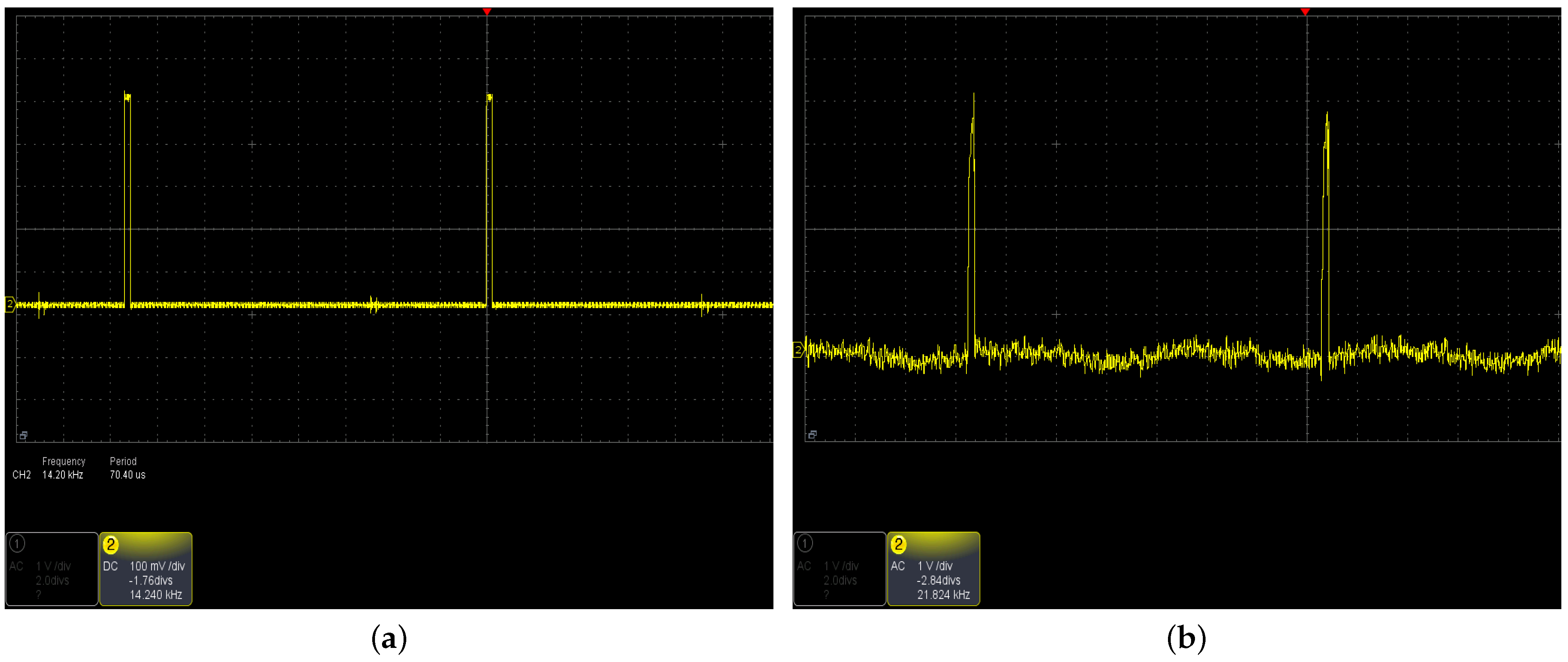
| Pulse repetition frequency , kHz | 14 | 14 | 14 |
| Source zenith angle | 88 | 45 | 45 |
| Horizontal divergence angle | 0.37 | 0.37 | 0.0034 |
| Vertical divergence angle | 0.08 | 0.08 | 0.0034 |
| Detector zenith angle | 45 | 88 | 88 |
| Field-of-view angle | 20 | 2 | 2 |
| Source height above the ground , m | 10, 20, 30 | 0.5 | 0.5 |
| Receiver height above the ground , m | 0.5 | 10, 20, 30 | 10, 20, 30, |
| 40, 45 | |||
| Baseline distance , m | 25, 50, 75, 100, | 25, 50 | 50, 75, 100, 150, |
| 125, 150 | 200, 385 |
| , m | ||||||
|---|---|---|---|---|---|---|
| , m | 10 | 20 | 30 | |||
| 25 | 0.0002 | 0.0011 | 0.0281 | 0.0313 | - | - |
| 50 | 0.0001 | 0.0006 | 0.0045 | 0.0134 | - | - |
| 75 | 0.0002 | 0.0011 | 0.0064 | 0.0150 | 0.9517 | 0.0846 |
| 100 | 0.0008 | 0.0035 | 0.0206 | 0.0292 | 0.9038 | 0.1316 |
| 125 | 0.0268 | 0.0589 | 0.2315 | 0.2485 | - | - |
| 150 | 0.2188 | 0.2739 | 0.2994 | 0.1849 | - | - |
| , m | ||||||
|---|---|---|---|---|---|---|
| , m | 10 | 20 | 30 | |||
| 25 | 0 | 0 | 0.0002 | 0.0009 | - | - |
| 50 | 0.0200 | 0.0461 | - | - | 0.0808 | 0.0654 |
| , m | , m | ||
|---|---|---|---|
| 50 | 10 | 0 | 0 |
| 20 | 0 | 0 | |
| 75 | 10 | 0 | 0 |
| 20 | 0.002 | 0.006 | |
| 100 | 10 | 0 | 0 |
| 20 | 0 | 0 | |
| 30 | 0 | 0 | |
| 40 | 0 | 0 | |
| 45 | 0 | 0 | |
| 150 | 10 | 0 | 0 |
| 20 | 0.021 | 0.028 | |
| 30 | 0.517 | 0.129 | |
| 200 | 10 | 0.001 | 0.002 |
| 20 | 0.002 | 0.007 | |
| 30 | 0.444 | 0.092 | |
| 385 | 20 | 0.099 | 0.084 |
| 30 | 0.694 | 0.179 |
| Experimental Series | ||||
|---|---|---|---|---|
| 1 | 0.842 | 0.913 | 0.920 | 0.962 |
| 2 | 0.945 | 0.996 | 0.963 | 0.997 |
| 3 | 0.865 | 1.000 | 0.927 | 1.000 |
Disclaimer/Publisher’s Note: The statements, opinions and data contained in all publications are solely those of the individual author(s) and contributor(s) and not of MDPI and/or the editor(s). MDPI and/or the editor(s) disclaim responsibility for any injury to people or property resulting from any ideas, methods, instructions or products referred to in the content. |
© 2023 by the authors. Licensee MDPI, Basel, Switzerland. This article is an open access article distributed under the terms and conditions of the Creative Commons Attribution (CC BY) license (https://creativecommons.org/licenses/by/4.0/).
Share and Cite
Tarasenkov, M.V.; Poznakharev, E.S.; Fedosov, A.V. Non-Line-of-Sight Atmospheric Optical Communication in the Visible Wavelength Range between UAV and the Ground Surface. Atmosphere 2024, 15, 21. https://doi.org/10.3390/atmos15010021
Tarasenkov MV, Poznakharev ES, Fedosov AV. Non-Line-of-Sight Atmospheric Optical Communication in the Visible Wavelength Range between UAV and the Ground Surface. Atmosphere. 2024; 15(1):21. https://doi.org/10.3390/atmos15010021
Chicago/Turabian StyleTarasenkov, Mikhail V., Egor S. Poznakharev, and Andrey V. Fedosov. 2024. "Non-Line-of-Sight Atmospheric Optical Communication in the Visible Wavelength Range between UAV and the Ground Surface" Atmosphere 15, no. 1: 21. https://doi.org/10.3390/atmos15010021
APA StyleTarasenkov, M. V., Poznakharev, E. S., & Fedosov, A. V. (2024). Non-Line-of-Sight Atmospheric Optical Communication in the Visible Wavelength Range between UAV and the Ground Surface. Atmosphere, 15(1), 21. https://doi.org/10.3390/atmos15010021