Article

Comparison of Portable and Large Mobile Air Cleaners for Use in Classrooms and the Effect of Increasing Filter Loading on Particle Number Concentration Reduction Efficiency

1
Institute of Fluid Dynamics and Thermodynamics, Otto von Guericke University Magdeburg, 39106 Magdeburg, Germany
2
Institute of Process Engineering, Otto von Guericke University Magdeburg, 39106 Magdeburg, Germany
*
Author to whom correspondence should be addressed.
Atmosphere 2023, 14(9), 1437; https://doi.org/10.3390/atmos14091437
Submission received: 21 July 2023 / Revised: 25 August 2023 / Accepted: 11 September 2023 / Published: 14 September 2023

Abstract

:
This study focuses on the effect of portable and large filter-based air cleaners (HEPA filters), which became popular indoors during the COVID-19 pandemic, and their suitability for classrooms (here 186 m3). The decay rates of the particle number concentration (PNC) were measured simultaneously at up to four positions in the room. It was found that the different air outlet configurations of the units have an effect on the actual PNC removal in the room when operated at the same volume flow rates. This effect of the airflow efficiency of the air cleaners (AP) in a classroom is quantified with an introduced Air Cleaning Efficiency Factor in this study to identify beneficial airflows. In this context, the effect of filter loading in long-term operation on the cleaning effect is also investigated. The emitted sound pressure levels of the APs are given special attention as this is a critical factor for use in schools, as well as power consumption. A total of six different devices were tested—two portable APs and four large APs. In order to achieve the necessary volume flow rates, three or four of the portable units were used simultaneously in one room, while only one of the large units was used per room. When used at the same air circulation rates in the room, the portable APs exhibit higher sound pressure levels compared to the large APs. At air circulation rates of 4–5 h−1, the portable APs exceeded a value of 45 dB(A). Two of the four large units reach sound pressure levels below 40 dB(A) at air circulation rates of 4–5 h−1, whereby both large units, which are positioned on the rear wall, realize a homogeneous dilution of the room air. This is achieved by an air outlet directed horizontally at a height above 2 m or diagonally towards the ceiling, which points into the room and partly to the sides. On the other hand, an air outlet directed exclusively to the sides or horizontally into the room at floor level to all sides achieves lower particle decay rates. To investigate the influence of the filter loading, three large APs were operated in a school for a period of one year (190 days with 8 h each). For the three APs, long-term operation leads to different changes in PNC reduction efficiency, ranging from −3% to −34%. It is found that not only the size of the prefilter and main filter has a significant influence, but also whether there is a prefilter bypass that negatively affects the loading level of the main filter. At the same time, it was shown that one type of AP, measuring the pressure drop across the filters and readjusting the fan, kept the circulation rate almost constant (up to −3%) over a year.

1. Introduction

In the course of the COVID-19 pandemic, which has spread worldwide since December 2019/January 2020 [1], the respiratory transmission of virus-containing particles has been identified as the dominant mode of transmission [2,3,4,5,6], while transmission via fomites plays a subordinate [7,8,9,10]. In the case of respiratory uptake, a distinction is made between droplet transmission and airborne transmission via aerosols. While droplet transmission involves particles in the range of >100 µm, aerosol particles are defined in the range of 0.001–100 µm [11]. Regarding airborne transmission, the particle class < 5 µm is of particular interest [12,13,14]. The different size ranges result in different propagation behavior. Thus, droplet transmission is possible indoors and outdoors due to the local propagation behavior in the air and the lack of dilution of droplet clouds. For airborne particles, a distinction must be made between short- and long-range. In the case of short distances, indoor and outdoor areas must be considered; in the case of long distances, transmission risk is only possible indoors [15]. This is because the concentration of fine particles, and thus the probability of infection, decreases rapidly outside enclosed spaces as a result of dilution by strong stretching and turbulent diffusion. In closed rooms, however, these small respiratory particles accumulate in the room air. Under normal respiratory activity, human breath contains mainly particles in the size range of 5 µm, these dehydrate over time after entering the room air and thus continue to decrease in diameter [16,17,18]. Particles in this range are called airborne because they can remain in the room air for up to several hours [19,20]. In such closed rooms, without supply air volume flow, a concentration reduction only takes place through deposition on surfaces and coagulation, whereby these effects are negligible in relation to ventilation (from an air exchange rate of 1.3 h−1) [21,22]. If viruses are attached to small airborne particles, which in turn have half-lives of more than one hour [23], an atmosphere can be created in closed rooms that favors infections [20]. A critical measure of the probability of infection indoors is the ratio of people to room volume [6], as well as their length of stay [24]. If both are high, such as in classrooms, it must be ensured that the respiratory aerosols, but also humidity, and emitted CO2 are removed from the room. Although at the beginning of the pandemic the role of schoolchildren in the spread of SARS-CoV-2 was sometimes considered to be minor [25], there were documented reports that schools contributed to the spread of infection [26,27,28]. Exhaled particles, humidity, and CO2 can only be removed in a controlled manner indoors by pre-installed ventilation systems that supply the room with fresh air and heat it if necessary. Such pre-installed systems are not widespread in German schools, which is mainly due to the high construction costs and the sometimes complex reconstruction measures. Therefore, the most widespread means of improving indoor air quality is window ventilation. This natural ventilation depends on factors such as ventilation area, temperature gradient between indoor and outdoor air, and wind direction and speed. Whether the wind speed (wind pressure) or the temperature difference is the dominant factor for the air exchange rate depends on the angle of incidence, according to [29]. In addition, studies show that the human factor also limits effective window ventilation. For example, on cold days, when window ventilation is more effective than on warm days [30], significantly less ventilation takes place as people are less likely to open windows for thermal comfort reasons [31]. Guidelines published by the German Federal Environmental Agency on ventilation state that window ventilation should be performed every 20 min [32]. However, a study involving more than 7000 measurement days in classrooms, ref. [33] showed that this guideline was followed in practice in less than 8% of cases. Thus, it is not possible to ensure a controlled and defined air exchange with solely natural ventilation.
In order not to rely solely on uncontrollable natural ventilation to remove respiratory particles from the indoor air, during the COVID-19 pandemic, some classrooms, but also other indoor spaces, were equipped with air cleaners (AP). APs can be installed indoors without structural alterations and work on the recirculation principle. The most common version works with HEPA filters through which the air is drawn into the device. In this case, the first particles are already separated from the intake air at a prefilter before the air is passed through a filter of the HEPA class, in which a minimum efficiency of 99.95% (for H13 and 99.995% for H14 according to [34]) in the range of the Most Penetrating Particle Size (MPPS) is realized. Afterward, the cleaned air is returned to the room. Some designs also have more than one prefilter and one HEPA filter. Furthermore, there are air cleaners that are based on UV-C, ionization, and plasma technology or ozone technology [35], which are not addressed in this paper.
Due to the recirculation principle, all air cleaners considered here have in common that they have no effect on the CO2 concentration nor on the air humidity, which is why they can only be considered as a supporting measure to natural ventilation. Similarly, masks and physical distance indoors can result in a reduction in the probability of infection [36], but this does not replace ventilation either.
There are already studies on filter-based APs in schools, where different models have been investigated in lessons with students and also without students in the room. Studies on APs in schools are summarized in Table 1.
The device types can be divided into portable APs and large APs. Large APs have heights of ≥1.6 m. The advantage of these large APs is that because of the higher volume flow rates, one unit might theoretically be sufficient for classrooms with volumes up to 200 m3. To evaluate the usefulness of APs, it is not sufficient to determine the theoretical air exchange rate from the AP volume flow rate and the room size. Rather, the actual cleaning effect in real room conditions should be evaluated or compared. This aspect is taken up by the so-called ‘expert recommendation’ of German scientists that specifically deals with air cleaners. This recommendation states that in order to achieve a significantly high cleaning effect, an AP should remove at least 90% of the particles from the room air within 30 min [43], which corresponds to a decay rate of λmin = 4.6 h−1. The decay rate of the particle number concentration (PNC) in a room can be described according to Equation (1), where C0 is the PNC at the start and Ct is the concentration at a time t.
C t = C 0 × e λ t
Similar decay rates can also be obtained by calculating the theoretical air exchange per hour via the supply of unpolluted fresh or cleaned air. Here, values of 36 m3/h/person are recommended [44], although these refer to supplied outdoor air. The value can therefore only be considered under the assumption that at an acceptable CO2 concentration according to [44], the exhaled PNC can also be kept at a low level. With a volume flow of 36 m3/h/person, decay rates of 4.5–4.8 h−1 result in a room volume of 186 m3 and 23–25 persons.
A further important aspect of the function of APs operated with HEPA filters is their long-term performance. With regard to APs that do not have a control unit depending on the pressure drop across the filters, it can be assumed that the cleaning effect decreases over time as filter loading increases and the preset volume flow rate decreases. In this paper, measurement results on the influence of filter loading on the cleaning efficiency of APs are presented for the first time, which thereby result from the use of the units in real school operation. In this regard, the Clean Air Delivery Rate (CADR) is used as an evaluation parameter. The CADR can be defined by the following two, Equations (2) and (3) [45].
C A D R t = V ˙ × η A P
C A D R m = λ A P λ n a t × V r o o m
Equation (2) only allows a general calculation of the CADR based on the AP volume flow rate V ˙ and the efficiency of the filters η A P . The theoretical CADRt does not allow a direct statement about the particle decay rate that will occur in a room when an AP is in operation. A more conclusive local CADR in the room can be determined using Equation (3). Here, the CADRm is determined considering the room volume (Vroom) and the practically measured decay rates (λ) resulting from Equation (1). Additionally, the decay rates are divided into those caused by the air cleaner (AP) and those caused by natural processes (nat). How the CADRs from Equations (2) and (3) can relate to each other is discussed in Section 2.4 (Scenario 2).
In order to better evaluate the long-term performance of APs, it is necessary to obtain more information about the volume flow control of the APs used. Here, it is crucial whether the APs used in studies measure the pressure drop across the filters and adjust the ventilator output to keep the CADR constant over the operating time. Additionally, the size of the filter surfaces influences long-term performance. However, for the application of APs, e.g., in schools, it is essential to prove that the APs still efficiently separate particles over a long continuous operating time. The impact on power consumption and sound level is also important from an economic and comfort level point of view. Therefore, in this study, two different large APs that were found to be most suitable for classrooms in preliminary measurements as well as one large unit with a different filter area are tested over a period of one year (190 days with 8 h each). According to the manufacturer’s specifications and the guidelines [46], no filter change is foreseen within the first year, which means that no significant cut in the particle separation efficiency in the room is to be expected. Although the units hardly differ externally, there are fundamental differences in the control system and filter areas that are not covered by guidelines and, thus, specifications. An expert recommendation of German scientists [43] even estimates the effect of the pressure drop increase in the filters of air cleaners, regardless of their area, as “mostly negligible”; for “relevant effects”, the expert recommendation refers to the efficiency reduction of CADR on discharging electrostatic filters, which, however, are not covered within this study. In this paper, we present key insights on the long-term performance of filter-based large APs.
The factors described in the previous section, which have hardly been addressed in the literature, will be investigated in this study. Therefore, one type of AP investigated in this study detects the pressure drop via the filters and adjusts the power of the ventilator so the CADRt is supposed to be kept constant; the other units do not readjust. The filter areas of the units without automatic adjustment of the fan power differ significantly, so conclusions can be drawn about the influence of the filter area or whether an increasing pressure drop of the filters have a relevant influence on the volume flow rates and therefore on the CADR.
In addition to the above-mentioned investigations, the APs are also examined individually and a comparison is made on whether it is advantageous to use several portable APs or one large AP in classrooms. Since either portable or large units have been investigated in the literature introduced here, our investigations provide for the first time a comparison of different air cleaners (portable/large) under the same boundary conditions. Based on the findings, a new evaluation factor for the effectiveness of the use of indoor air cleaners is introduced.

2. Air Cleaners and Setup

This study focuses on the investigation of the use of air cleaners in classrooms. Primarily, the influence on the particle number concentration (PNC) in the room air is investigated. In the complex field of application in schools, however, the PNC is not the only decisive parameter for evaluating the usefulness of these devices or distinguishing the advantages and disadvantages of individual devices. Therefore, among other things, the noise level and the influence of long-term operation are investigated. In the following, first, the characteristics of the APs used are documented, then the measuring instruments are introduced, and finally, the experimental setup with the investigation scenarios is presented.

2.1. Portable/Mobile/Large Air Cleaners Used

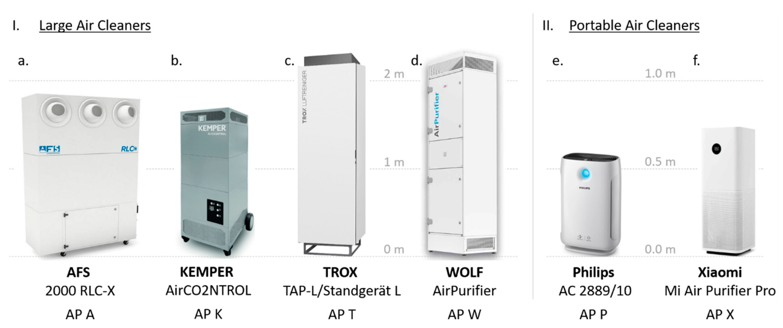
In this study, six different APs were examined. The different units are shown in Figure 1. Of the four large unit types, two are mobile with castors and a height of <1.9 m (AP A, AP K), while two with a height >2 m are fixed to the wall (AP T, AP W). The two portable APs (AP P, AP X) tested have heights of less than 1 m.

2.1.1. Portable Air Cleaners

Portable air cleaners are installed in many schools. It is known from the authors’ environment and local research that these APs were mostly purchased on the initiative of teachers, principals, and/or parents of students. The reasons for purchasing portable APs compared to large APs were lower purchase costs and the possibility of transport and installation without professional aids/transporters.
There are many portable air cleaners on the market and, for this reason, a selection had to be made for the present study. The approach in the selection of devices was to choose widely used devices. Finally, two different portable APs were selected for the investigation. The AC 2889/10 by Koninklijke Philips N.V. (Amsterdam, The Netherlands), hereinafter referred to as AP P, and the Mi Air Purifier Pro by Xiaomi Tech (Beijing, China), hereinafter abbreviated as AP X. The AP P was selected based on a test conducted by Stiftung Warentest, the most renowned non-profit consumer organization in Germany, in which the device emerged as the test winner in 2020 [47]. A comparable predecessor model (AC 2887/10) of the unit was also tested in a study at the Goethe University in Frankfurt am Main (Germany) [40]. The AP X is the test winner of the latest study (as of December 2022) conducted by Stiftung Warentest in January 2022 [48].
Figure 1. Illustrations of (I). large air cleaners covered in this study: (a). AP A [49], (b). AP K [50], (c). AP T [51], (d). AP W [52], as well as (II). portable devices: (e). AP P [53], (f). AP X [54].
Atmosphere 14 01437 g001
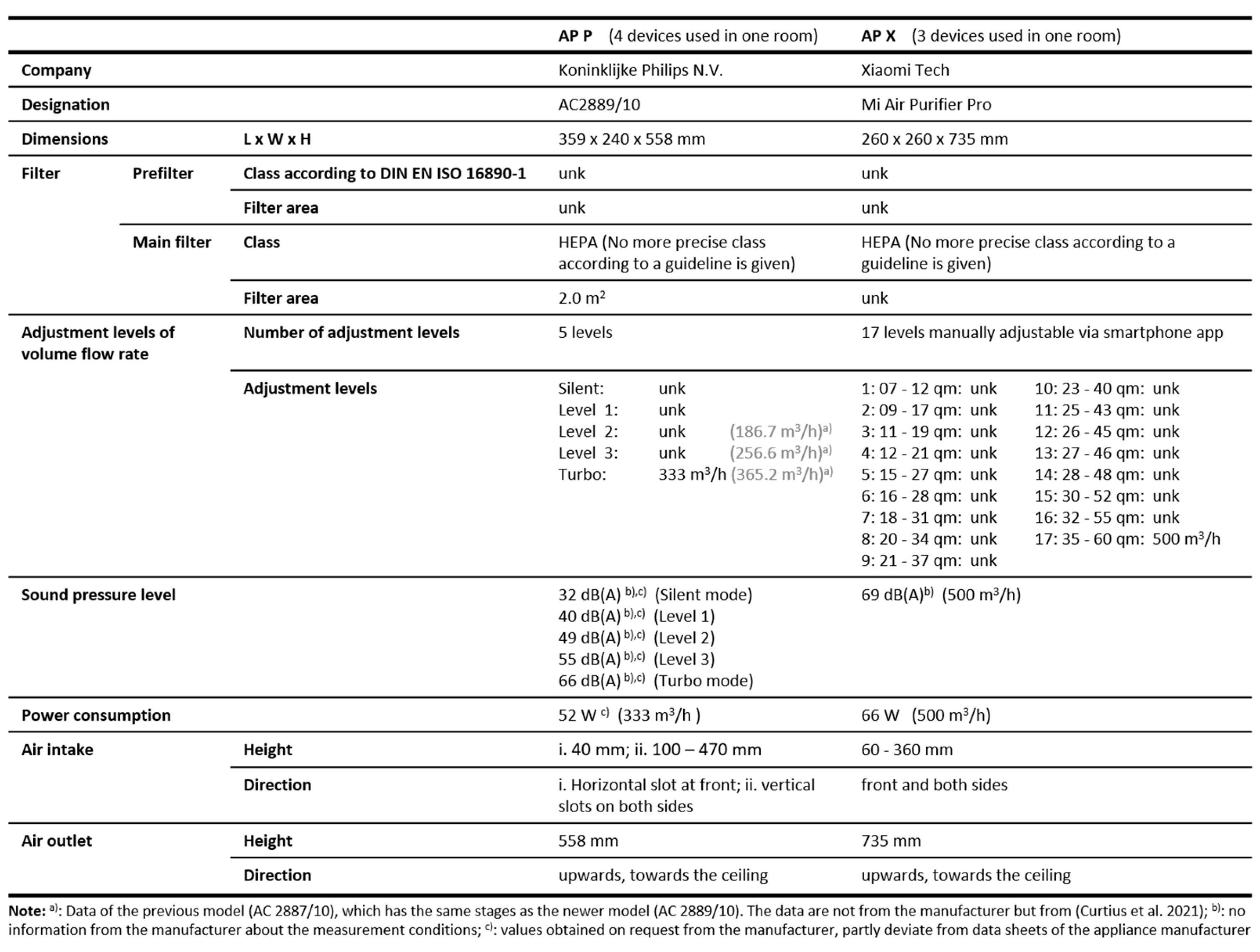
For our study and the selection of devices in general, the information in the data-sheet is an important source of information. In our view, the scope of the manufacturer’s information on both devices is to be criticized to a considerable extent. No comprehensive information on volume flow rate, sound power/pressure level, and power consumption is given for the different settings. This fact is problematic as it makes procurement of public funds and thus the use in schools more difficult. It should be added here that no further data could be obtained from the companies (Philips), nor was there any response to an enquiry (Xiaomi). Furthermore, it should be mentioned that AP P is intended for use in classrooms (refers to the predecessor model Philips AC2887/10: [55]). The AP X is not explicitly advertised for this, but rather for use in private homes.
Both portable APs, AP P and AP X, have a prefilter and a HEPA filter, which, however, is not further classified in the data sheet, neither according to the European standard [34] nor according to the American standard [56], both of which have been merged into the international standard [57], but still exist individually. The air intake is at the front and sides of both units, and the air outlet is directed upwards towards the ceiling, creating a vertical introduced turbulent mixing airflow. Since the manufacturer’s data on the devices are not sufficiently available, the device data were supplemented with our measurement data, summarized in Table 4.

2.1.2. Large and Mobile Air Cleaners

In this study, units with a height of ≥1.6 m are classified as large air cleaners. The large APs investigated have in common that they can achieve volume flow rates of >1000 m3/h. The devices considered are the RLC2000-X from AFS Airfilter Systeme GmbH (Uebrigshausen, Germany), hereafter referred to as AP A, the AirCO2NRTOL from KEMPER GmbH (Vreden, Germany), hereafter AP K, the TAP-L from TROX GmbH (Neukirchen-Vluyn, Germany) (AP T), and the AirPurifier from WOLF GmbH (Mainburg, Germany) (AP W).
The AP A and AP K can be described as large mobile APs, as both are equipped with castors/wheels and the height of the unit is smaller than the standard doorway height in each case. The unit height of AP T and AP W exceeds the door height and they have to be firmly screwed to the wall. Thus, according to our definition, they no longer belong to the group of mobile units.
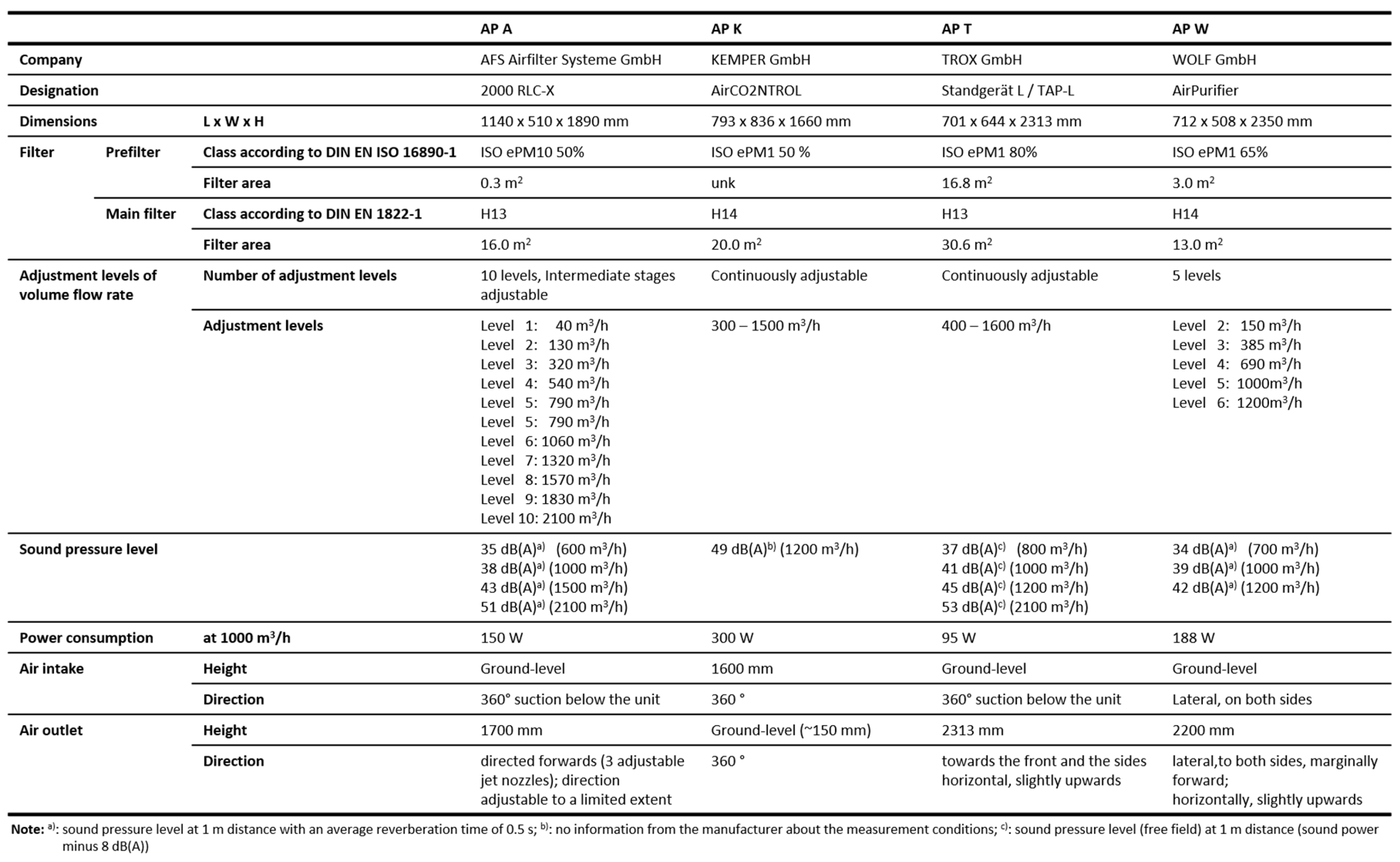
The AP A, AP T, and AP W units draw in the air at floor level. AP A and AP T draw in air from all sides, AP W only from the two sides, which means that no furniture can be placed directly next to it. Furthermore, all APs are equipped with a prefilter and a HEPA filter. The filter classes and respective areas differ and are summarized in Figure A2 of the Appendix A. The prefilter areas vary from 0.3 to 16.8 m2 and the areas of the HEPA filters from 13.0 to 30.8 m2. The prefilters are intended to separate coarser particles in the first step before the aerosol passes through the HEPA filter. This results in different replacement intervals for the filter types, which according to the standard [46], are one year for prefilters and two for the main filters. However, reference is also made to the manufacturer’s specifications, which may differ in some cases. Only AP A has a different specification for the HEPA filter, which stipulates a replacement interval of one year. All units have an EC fan, which is installed after the filters (AP A, AP K, AP T) or between the prefilter and the main filter (AP W).
AP K is the only air cleaner that adds filtered air to the room at floor level, all other units have this outlet located at the top of the unit, therefore AP K is considered separately in the following. The discharge of the air separated from the particles takes place at a height of >1.7 m in order to be able to flush the entire room, which means that, in contrast to portable devices, a single AP per classroom is sufficient [41]. In this case, the outlet is directed to the front (AP A), to the front and sides (AP T), or to the sides only (AP W), as illustrated in Figure 2. Another significant difference is in the internal control of the units. For example, the volume flow rate of AP A and AP W can be set to different levels by means of a wheel (Figure A2), whereby the volume flow rate data refer to unloaded, new filters. If the loading of the filters and thus the pressure drop over the filters increases, the units do not readjust. In contrast, AP T measures the pressure drop across the filters and adjusts the power as the pressure drop increases, so that the circulated volume should remain constant even when the filters are loaded. Adjusting the power is accompanied by increasing power consumption over the operating life. The power consumption of the devices is specified by the manufacturer as 150 W (AP A), 95 W (AP T), and 188 W (AP W) (Figure A2). These values refer to volume flow rates of 1000 m3/h (AP T, AP W) or 1060 m3/h (AP A).
An important criterion for use in school classrooms is the noise level of the units. The manufacturer’s specifications state sound pressure levels of 38 dB(A) (AP A), 41 dB(A) (AP T), and 39 dB(A) (AP W) at a volume flow rate of 1000 m3/h (AP T, AP W) and 1060 m3/h (AP A), respectively.
The AP K differs considerably from the other three units. As summarized in Figure A2, the air intake of AP K is located at a height of 1.6 m. The filtered air, however, is discharged at floor level. Both the intake and the outlet are directed to all sides so a reduction in efficiency is to be expected if the unit is placed against a wall (Figure 2). The filter area for the prefilter is not specified, but the main filter is comparatively large (20 m2). However, the power consumption of this AP is comparatively high (Figure A2).

2.2. Measurement Equipment

2.2.1. Aerosol Spectrometer and Generator

Up to four aerosol spectrometers of the type AQ Guard from PALAS GmbH (Karlsruhe, Germany) were used for the measurements. The spectrometers are designed for indoor air hygiene measurements and cover the particle measurement range 0.178–17.780 µm in 64 size classes. The particle measurement of the spectrometer is carried out by scattered light analysis on individual particles, which are guided through a defined measurement volume that is homogeneously illuminated by a polychromatic LED light source. The number of particles per time unit is determined on the basis of the scattered light pulses generated by the particles. The maximum measurable PNC is 20,000 particles/cm3, with a mass-related maximum value of 20,000 µg/m3.
In addition to the number of particles and the size class distribution, the measuring device also outputs various classes of particulate matter (PM1, PM2.5, PM4, PM10), as well as temperature, pressure, relative humidity, CO2 concentration, and volatile organic hydrocarbons (TVOC). The specifications given by the manufacturer can be found in the appendix of [41].
The aerosol generator PAG 1000 from PALAS GmbH was used to generate well-defined aerosols. It provides a volume flow rate of 0.9–4.6 L/min. Di-ethyl hexyl sebacate (DEHS) and similar oils as well as NaCl and KCl can be used for particle generation. In this study, DEHS was used. The flow rate of the aerosol generator can be adjusted (high and low) in each case from 0 to 100%. Using DEHS at the level high and 100% (4.6 L/min), 1.2 × 10⁹ particles/s (1.6 × 10⁷ particles/cm3) with a size of ≥0.2 µm are generated.

2.2.2. Sound Analyzer and Power Meter

To measure the sound level of the units, a 2260 Investigator module sound analyzer with the BZ7201 sound analysis software from Hottinger Brüel & Kjær GmbH (Darmstadt, Germany) was used. This is a class 1 sound level meter (IEC and ANSI). The microphone is a type 4189 permanently polarized free-field microphone from Hottinger Brüel & Kjær GmbH. The A-weighted long-term average sound level was measured for 20 s.
Two different power meters were used simultaneously to measure the power consumption of the devices. The Bearware Power Meter 302717 from WD Plus GmbH (Hannover, Germany) and the SEM 16+ from Nordwestdeutsche Zählerrevision Ing. Aug. Knemeyer GmbH & Co. KG (Bad Laer, Germany) both have a measuring range of 0.1–3680 W with an accuracy of 2% and 1%, respectively.

2.3. Setup of the Test Series

The classrooms in which the measurements take place are identical to the ones in our previous work [41] and can be considered a typical classroom for Germany in terms of dimensions (9.4 × 6.5 m). The volume of the room is 186 m3 with a ceiling height of 3.05 m. For more information on the arrangement of the furniture and lamps, we refer to [41].
The classrooms with identical dimensions are equipped with different APs. In the case of the large air cleaners (AP A, AP K, AP T, AP W) only one unit is being used and in the case of the portable units, three (AP X) or four (AP P) units are used. The locations of the units are shown in Figure 3 and assigned to the different units in Table 2.
The aerosol spectrometers are set up at the measurement locations marked in Figure 3. The coordinates of the exact locations are given in Table A1 of the Appendix A.

2.4. Experimental Procedure and Scenarios Investigated

All investigations in this study are carried out under the same, known conditions. There are no people in the room during the measurements and the windows and doors of the room are closed. Before the actual measurement, the particles are artificially generated by an aerosol generator. Aerosol particles are generated for 15 min and distributed homogeneously in the room by a fan. After the generator is switched off, the PNC in the room is further homogenized by a fan for 3 min. This is monitored in real-time by the aerosol spectrometers so that after a total of 18 min an aerosol concentration of 5500–6000 particles/cm3 on average can be detected. This is followed by the measurement with air cleaners turned on and with the aerosol generator and the fan switched off. The following measurement scenarios are covered:
Scenario 1: In the first step, the local homogeneity of the time-resolved PNC is measured by means of four measuring positions distributed in the room (Figure 3). Measurements are also carried out without APs to map the natural decay behavior (λnat) of the particles in the room. Especially with large air cleaners where only one device is used, it must be proven by measurement that the decay rates of the PNC are similar everywhere in the room. Furthermore, the set volume flow rates are examined by separate measurements in order to be able to classify any differences in the measurement results obtained. The volume flow rates are calculated from the flow velocities in an attached pipe by means of a small vane anemometer. Here, eight measuring points per radius are used, while the measurement radii in the circular pipe are determined according to the trapezoidal rule [58].
Scenario 2: In the second step, the measured PNC decay behavior in the room, caused by the applied air cleaners at different set volume flows, is addressed. Recommendations already introduced in Section 1 provide for air circulation rates of 4–5 h−1, which should be realized in the room. Based on the measured decay rates at different measuring points, statements about beneficial air flow patterns and separation efficiencies of the different devices can be derived. This comes up against its limits when different units cannot be set to the same volume flow rate. Therefore, an efficiency factor is introduced below to compare the particle decay rate caused by different APs at different volume flows in each case.
To be able to assess the cleaning efficiency of an AP within a specific room situation, the Air Cleaning Efficiency Factor (ACEF) is introduced. The ACEF relates the decay rate measured in the room to the set volume flow rate of the air cleaner V ˙ s . Only the portion of the decay rate caused by the air cleaner is considered.
A C E F s = λ A P λ n a t × V r o o m V ˙ s = C A D R m C A D R t ( s ) × η A P
According to Equations (1) and (2), the ACEFs can also be determined by the CADRm measured at a measuring point in the room in relation to the CADRt theoretically provided by the unit, which is then multiplied by the filter efficiency. Here, the CADRt is related to the volumetric flow rate V ˙ s set on the unit, and thus to the manufacturer’s specification. It is convenient to use the set volume flow rate, since in practical applications the true volume flow rate would have to be determined with relatively high effort. The ACEF is proportional to filter efficiency according to Equation (4). It should be mentioned here that lower filter efficiencies in a certain range (e.g., >99%) are not necessarily disadvantageous, as the lower flow resistance leads to lower power consumption and lower noise emissions, which is further explained in Section 3.3. Therefore, the ACEF must always be assessed in relation to noise emissions as a critical measure.
Since APs have both the air inlet and outlet on the device and thus in the immediate vicinity, higher air velocities are achieved in the area of the outlet in order to avoid so-called “short-circuiting” of the filtered air. The turbulent mixed flow (or dilution flow), with a tangential flow roll with horizontal (large APs) or vertical initiation direction (portable APs), leads in the optimum case to ACEF ≈ 1, assuming a HEPA filter which, together with a prefilter, has a filter efficiency of >99.95%. In this case, CADRtCADRm from Equations (2) and (3) applies. An ACEF of less than 1 indicates a non-optimal turbulent mixed flow, for example, due to “short-circuiting” or filter efficiencies that are significantly lower than 1. If the ACEF is >1, the condition of partial displacement flow is reached, which, in this case, means that the air sucked in by the AP would have a higher PNC than the average room air. A real displacement flow with a low degree of turbulence in the conventional sense cannot be generated by APs, however.
If larger discrepancies are found in the calculation of the ACEF or if manufacturer data on volume flow rates are missing, the efficiency factor can be determined on the basis of a measured volume flow rate V ˙ m with new filters (Equation (5)). In this case, the theoretical CADRt (Equation (2)) therefore refers to the measured (m) volume flow.
A C E F m = λ A P λ n a t × V r o o m V ˙ m = C A D R m C A D R t ( m ) × η A P
Since the use of an AP in schools can only be recommended if the current noise limits are complied with, the ACEF must always be seen in the context of noise emissions. Different international standards define the same maximum sound pressure levels. For example, a German workplace guideline [59] and the VDI guideline [60] specify a maximum value of 35 dB(A), which is also defined by the American National Standards Institute [61] for classrooms. In a statement by the Commission on Indoor Air Hygiene (IRK) at the Federal Environment Agency in Germany, continuous sound levels of more than 40 dB(A) are considered “disturbing for the performance of lessons” [62]. Thus, on this basis, a value of max. 35 dB(A) is aimed at, and a value of 40 dB(A) should not be exceeded. In addition to the sound level, power consumption is also measured, which is an important economic criterion, especially when operating several units in schools over a longer period of time. The results of the investigations show which air cleaners are suitable for schools.
Scenario 3: The third phase of the study focuses on the long-term performance of those APs that were able to prove their suitability for classrooms in the previous phase. In that case, the APs were tested again after one year in operation. The units were in use every school day, which results in an operating duration of approximately 190 days of 8 h. According to the guideline [46], the prefilters must be changed annually, and the HEPA filters every second year unless otherwise specified by the manufacturer. The effect of the filter loading of the different APs varies due to different filter areas or the use of a volume flow control technology.

3. Results and Discussion

In this chapter, the local particle number concentration (PNC) curves when using different air cleaners at different measuring points in the room are first analyzed before the volume flow rates of the air cleaners are measured and compared with the manufacturer’s specifications for further investigations. The results of the decay rates due to the different air cleaners are then evaluated at different volume flows and also classified concerning the continuous sound level and the power consumption of the devices for operation in the classroom. In the final step, the influence of long-term use (190 days of 8 h each) and the associated increasing filter pressure drop are quantified, considering the influence of filter surfaces, possible leakage at prefilters, and automated power adjustment.

3.1. Evaluation of the Spatial Homogeneity of the PNC in a Classroom (Scenario 1)

When considering aerosol loads indoors, it must be taken into account that the PNC can vary at different locations. For this reason, it is necessary to measure the PNC at several positions simultaneously. Especially when using room air cleaners, lower PNC may be measured in well-flushed room areas than in poorly flushed room areas. The change in PNC over time is described by the particle decay rate (λ). Quantification and comparison of particle decay rates in different room positions is the first step of this study. Therefore, the local decay rates of the PNC were measured at four measuring points (MP 1–4) in the room according to the procedure introduced in Section 2.4. At least three repeated measurements per variation were carried out.
When considering decay rates, the natural reduction of the PNC in rooms must be taken into account. This is mainly due to the deposition of particles on surfaces as a result of the convective room flow and leaks around doors and windows. For the room situation prevailing in this study, the natural decay rate λnat was measured separately. Without the use of APs, the average natural decay rate (λnat) is 0.092 h−1, whereby the deviations at MPs 1–3 are small (0.092–0.136 h−1); MP 4, however, with 0.028 h−1, is significantly lower. One possible reason is the position of MP 4, which is in a corner. Here, a lower convective flow velocity is to be expected in the corner, opposite the windows and heaters, so that deposition processes on surfaces might be lower.
When using APs at a set volume flow of 1000 m3/h (AP K, AP T, AP W) or 1060 m3/h (AP A), the decay rates at measurement points (MP) 1–4 (Figure 3, Table A1) vary less for the large APs with the air outlet at the top of the unit than for AP K, where it is at floor level. The maximum deviation between the decay rates at the different MPs 1–4 is 2% for AP A, 2.5% for AP T, and 4% for AP W. It is found that a forward discharge direction of the filtered air into the room is advantageous (AP A, AP T) compared to an exclusively lateral discharge direction (AP W). If the filtered air is supplied to the room at floor level, as in the case of AP K, there is a systematic deviation of the decay rates at the measuring points. For example, the decay rate at MP 4 (Figure 3), which is positioned closest to AP K on the right, is up to 11% higher than that of MPs 1–3. MP 3 is almost the same distance from AP K as MP 4, but there are several chairs and a table between MP 3 and the AP.
A homogeneous dilution of the room air (room volume 186 m3) with filtered air from the APs can thus be demonstrated for the large air cleaners at a set volume flow of around 1000 m3/h, with the mentioned limitation of AP K.

3.2. Verification of the Manufacturer’s Specifications Regarding the Volume Flow Rates

One of the main parameters when considering room air cleaners is the volume flow rate. This has a significant influence on the cleaning effect of the devices. Since various devices are compared in this study, it is necessary to know the actual volume flow rates achieved.
The large APs differ from one another in the setting of the power levels and volume flow rates. The volume flow rates of AP A and AP K can be continuously adjusted via potentiometers; AP T is also continuously controlled via a digital controller. On the other hand, AP W can be set to five defined volume flow rates (Figure A2). Within the scope of our volume flow measurements, in which two pipes with an inner diameter of 191 mm were installed in front of the respective air inlet, in which the velocity profile was measured at eight different radii according to the trapezoid rule [58], deviations of set and measured volume flow of ≤10% were measured for the large units, which supports the manufacturer’s specifications with regard to the measurement uncertainty and, thus, fundamental differences in measurement results cannot be attributed to the volume flow. In the measurements with new filters, at a set volume flow of 1000 m3/h, AP K showed 1001 m3/h, AP T 1026 m3/h, and AP W 968 m3/h. In our measurements, AP A has a volume flow of 967 m3/h with a set flow rate of 1060 m3/h.
With the portable APs, AP P shows a measured volume flow rate of 322 m3/h with a set of 333 m3/h. AP X shows a measured volume flow rate of 379 m3/h with a set volume flow according to the manufacturer of 500 m3/h. Due to the strong deviation between the nominal value and the measured value of AP X, the measurements were carried out on a second device, with the same outcome. At this point, it must be mentioned that the measurement method used has a measurement uncertainty of up to 10%. However, the significant deviation for AP X cannot be explained by this. The measured volume flows of the other adjustment levels are summarized in Table 4.

3.3. Decay Rates of Investigated APs at Different Set Volume Flows (Scenario 2)

This measurement campaign aims to evaluate the removal of aerosol particles of different APs at different set volume flows. The parameter for evaluating the cleaning effect of APs in specific room situations is the particle decay rate. To determine the decay rate, the PNC are measured over time and Equation (1) is fitted using the least squares method. This results in the corresponding decay rates (λ). The greater the decay rate determined, the better the cleaning effect of an AP. The Air Cleaning Efficiency (ACEF) can be determined based on the decay rate and the flow rate set or measured at the AP according to Equations (4) or (5). The measurements in this section were performed with new filters according to the procedure described in Section 2.4.
I.
Large APs
Three of the four large air cleaners discharge the filtered air at a height of more than 2 m horizontally (AP T, AP W) or diagonally upwards (AP A). The most important difference between the three APs is the discharge direction of the filtered air, which is shown qualitatively in Figure 2. This results in significant differences in the particle decay rates in the room, measured at two measuring points (MP1 and MP2, according to Figure 3/Table A1). The measurement points in Figure 4 represent mean values from at least two repeated measurements. The reproducibility under the controllable conditions was high for successive repeated measurements, with deviations below 4%. The diagrams in Figure 4 show the decay curves (solid lines) according to a regression of Equation (1). It can be seen that the measured data are very well represented by Equation (1), especially for AP A (Figure 4a) and AP T (Figure 4b), with coefficients of determination of almost 100% (min. 99.94%). The minimum coefficient of determination of the decay curve fit for AP W is also high at 99.28%. The agreement between MP 1 and 2 is good for AP A and AP T regardless of the set volume flow rate range of 790–1200 m3/h, with deviations of a maximum of 1.5%. AP W shows deviations between the measuring points of 8.5% at set 690 m3/h. At higher set volume flows, however, the deviation between the measuring points is significantly lower (<3%) when using AP W.
Significant differences were found in the decay rates of the measured PNC curves when using the different APs. The results are summarized in Table 3 and shown in Figure 4. AP W, with the air outlets on the sides of the unit, has the lowest Air Cleaning Efficiency Factor (according to Equation (4)), which, however, increases with increasing volume flow. Thus, values of ACEFs of 0.62, 0.67, and 0.76 could be measured at set volume flows of 690, 1000, and 1200 m3/h, respectively. The filtering efficiency with the prefilter and the HEPA (H14) filter is >99.995% and, therefore, is not the factor that leads to the low ACEFs. Due to the ACEFs of well below one and the predefined fixed setting levels of AP W (levels ‘4’, ‘5’, ‘6’; see Table 2), a volume flow of 1200 m3/h must be set here for a room volume of 186 m3 in order to achieve a decay rate of ≥4 h−1. With a set volume flow of 1000 m3/h, this is not achieved with 3.66 h−1.
The air cleaners AP A and AP T show comparable results among themselves, which result from the similar airflow, which, in both cases, is directed forward into the room above head level creating a horizontally introduced turbulent mixed ventilation. AP T achieves a decay rate of 4.6 h−1 at a set flow rate of 800 m3/h, while AP A achieves 4.3 h−1 at a set flow rate of 790 m3/h (Table 3). The high values are achieved due to the good flow distribution in the room, which can be explained by the large discharge distance of the filtered air into the room, which, unlike AP W, can use the entire length of the room without reaching a wall (Figure 2). This is also reflected in the ACEFs (Equation (4)) with an ACEFs,A = 0.99 for AP A and an ACEFs,T = 1.07 for AP T. The value quantifying the efficiency remains the same for both air cleaners in the measured volume flow range (790–1200 m3/h). Thus, for higher volume flows of 1200 m3/h, decay rates of up to 7 h−1 result for AP T (Table 3).
If the filtered air is introduced into the room at floor level, as is the case with AP K, the proportion of the measured CADRm at the measuring points is 25% lower than the set and measured volume flow of the unit (ACEFs,K = 0.75). The CADRm results from the decay rate of the particles in the room of 4.1 h−1 at a set volume flow of 1000 m3/h. It should be noted that the design of the air outlet, which is also partly directed towards the wall (Figure 2), can also be expected to reduce the ACEFs,K. The flow of filtered air directed towards the room wall cannot spread unhindered in the room and is partly drawn in again by the unit with a particle load that is significantly below the average PNC in the room (“short circuit”). It cannot be conclusively clarified here what share of the air outlet at floor level or the partial airflow towards the wall is responsible for the low ACEFs,K, but the results (e.g., Section 3.1) indicate that both play a significant role.
If the air cleaners are used in classrooms, the decay rates must necessarily be seen in the context of the noise levels of the units. The measured A-weighted equivalent continuous sound levels of the air cleaners AP A and AP T do not exceed the value of 40 dB(A) at measured decay rates of up to 5.8 h−1. At decay rates of up to 4.7 h−1, a value of 35 dB(A) is not exceeded. The air cleaners AP K and AP W have higher continuous sound levels so that no decay rates ≥ 4 h−1 at 40 dB(A) or less can be realized for a room volume greater than or equal to 186 m3. The measured sound levels are summarized in Table 3.
Sound emissions of the units depend, among other things, on the fan power. This, in turn, depends on the pressure drop of the filters and the volume flow rate. By installing a filter with a lower filter efficiency and, thus, a lower flow resistance and pressure loss, the fan power can be reduced. It must be noted that a lower filter efficiency must be compensated for by an increase in the volume flow. Since the filter efficiencies of the different filter types only change in fractions of a percent, the necessary volume flow adjustment is marginal. For using filters with very low efficiencies, the necessary increase in the volume flow rate might be significant. In such cases, the increase in the flow velocity in the room can lead to thermal discomfort for people. Noise emissions and local air velocities in the vicinity of people are critical factors, especially for classrooms, which thus limit the maximum decay rate to be realized when using APs in classrooms. From the authors’ point of view, however, an H13 filter, for example, should be preferred to an H14 filter, since the filter efficiency of the H14 class is only minimally better (99.995% instead of 99.95% for H13, according to [34]) and can be compensated by a marginal increase in the volume flow. Here, the use of H13 filters not only results in cost reductions compared to H14 filters but also in lower noise emissions, measured with AP K at 1000 m3/h. The use of an H13 filter using AP K results in a reduction in the A-weighted equivalent continuous sound level of 1.5 dB(A), compared to an H14 filter, measured at a distance of 1 m at a height of 1.1 m. This is reasonable because a lower pressure drop across the filter reduces the required fan power.
The results show in the summary that the air outlet direction plays a decisive role for large air cleaners within the examined room geometry. An air outlet to the front towards the center of the room or to the front and sides shows a higher decay rate and, thus, a more efficient turbulent mixed flow than with an air outlet exclusively to the sides. Under the present conditions, the AP A and AP T units were able to achieve decay rates of up to 5.8 h−1 at low continuous sound levels of ≤40 dB(A) (see Section 2.4), which is a key factor for use in classrooms.
From an economic point of view, the power consumption of the units is an important factor. The power consumption (Table 3) of AP T is more than 30% lower than the comparable AP A and AP W. AP K with 248 W is significantly higher than the other units, including the portable units, which are discussed in the following section.
II.
Portable APs
For the portable units tested, three units (AP X) or four units (AP P) per room (186 m3) were used. Since the manufacturers do not specify any volume flow rate information for the individual operating levels, except for the maximum level in each case, several levels were tested (Table 4). The volume flow rates were additionally measured (Section 3.2) and, due to the incomplete volume flow rate data provided by the manufacturers, the efficiency of particle removal in the room by the devices is thus related to the measured volumetric flow rates (Equation (5)), not to manufacturer specifications as is the case with the large APs.
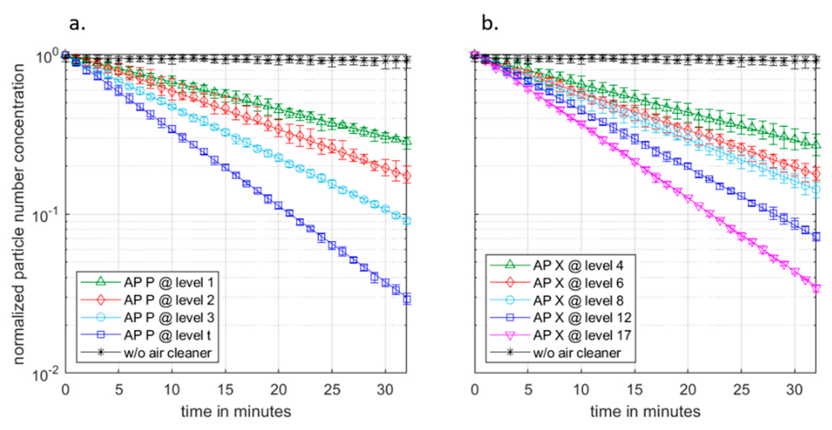
The decay curves according to Equation (1) of AP P at operating levels ‘1’, ‘2’, ‘3’, and ‘turbo’ are shown in Figure 5a, and those of AP X at levels ‘4’, ‘6’, ‘8’, ‘12’, and ‘17’ are shown in Figure 5b. Each measurement was carried out at least twice with two measuring points (MP1, MP2; Figure 3). The points shown are mean values of the measurements and, due to the marginal deviation of the results at MP1 and MP2, also of the two measuring points.
In AP P, where four units were used in the room, 10% of the initial concentration can be reached after approximately 30 min at level ‘3’ (Figure 5a). Thus, the decay rate at level ‘3’ is 4.51 h−1. In ‘turbo’ mode, the decay rate averages 6.59 h−1. The Air Cleaning Efficiency Factor (ACEFm), here related to the measured volume flow rate, remains at a comparable level for stages ‘2’–‘t’ with 0.94–1.01. These results must be seen in the context of sound emissions, again. For four units used, the continuous sound levels are 47.9 dB(A) (level ‘3’) and 53.9 dB(A) (level ‘turbo’), measured at a distance of 1 m at a height of 1.1 m from one air cleaner, while the other air cleaners were positioned according to Figure 3 and switched on. The values are summarized in Table 4 and considerably exceed the maximum values from the guidelines introduced in Section 2.4. If AP P is operated at levels ‘1’ or ‘2’, the sound emissions decrease significantly, but decay rates of less than 3.5 h−1 are not sufficient (meaning < 4 h−1) for classrooms.
AP X (3 units with a room volume of 186 m3), like AP P, can efficiently remove particles from the room. The ACEFm is in the range of 1.02–1.09 for levels ‘8’, ‘12’, and ‘17’. A decay rate ≥ 4 h−1 could be reproducibly demonstrated from level ‘12’ with 5.04 h−1, whereby levels ‘9’–‘11’ were not examined due to a large number of adjustable levels. Level ‘8’ realizes a particle decay rate of 3.63 h−1 at a measured continuous sound level of 45 dB(A). According to the guidelines introduced in the introduction, the decay rate is not sufficient for classrooms; moreover, the sound level is already too high. At the continuous sound level of 35 dB(A) (level ‘4’) to be aimed for in classrooms, the measured decay rate is 2.43 h−1. The results are summarized in Table 4.
In summary, we conclude that portable air cleaners can reduce the PNC in the room as efficiently and uniformly as large air cleaners (AP A, AP T). The suitability for permanent use in classrooms, however, is not given due to the high sound emissions. For example, a continuous sound level of 40 dB(A) is already exceeded at decay rates of 3.1–3.4 h−1, which here refers to a room volume of 186 m3. Based on the measured volume flow rates provided by the units, however, the resulting decay rates are high, which results in a high ACEFm in the range of 0.94–1.09.
Since a decay rate of the particles in the room of ≥4 h−1 can only be realized at continuous sound levels significantly above 40 dB(A), the portable devices were not investigated in a long-term test in schools and are thus missing in the investigations of the following scenario 3.

3.4. Influence of the Filter Loading Level after an Operating Period of One Year (190 Days of 8 h) (Scenario 3)

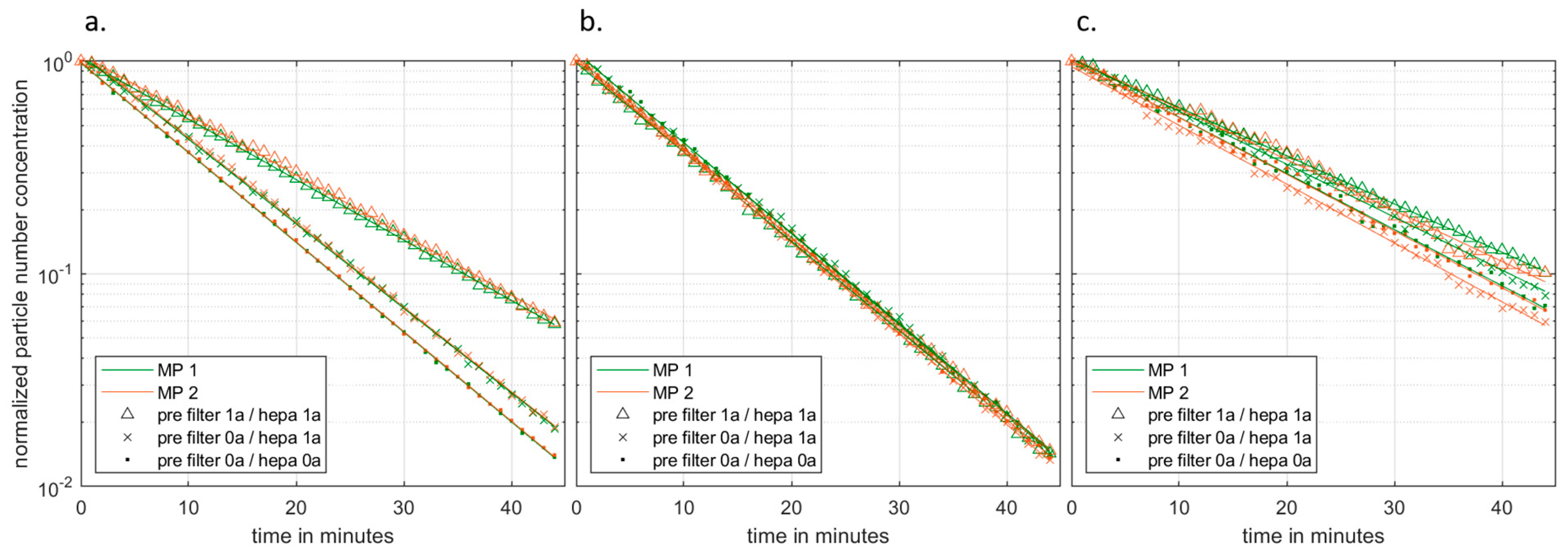
The air cleaners AP A, AP T, and AP W were operated in a primary school over a period of one year in daily school operation (190 days of 8 h). The APs differ in the area of the prefilters (AP A: 0.3 m2; AP T 16.8 m2; AP W: 3.0 m2) and in the classification according to the international standard [63] (see Figure A2). The same standards apply to the replacement interval, which is specified as one year. The main filters (AP A: 16.0 m2 (H13); AP T 30.6 m2 (H13); AP W: 13.0 m2 (H14)) of the HEPA class according to [34] do not have to be changed in the first year either (every second year unless the manufacturer’s specifications differ). Due to the increasing degree of loading of the filters over the year, the pressure drop across the filters increases with constant fan power, resulting in lower cleaning performance. This can be seen in the PNC decrease at MP 1 and 2 when using AP A (set volume flow 1060 m3/h) in Figure 6a. The diagrams show the decay curve (according to Equation (1)) of the PNC when using new prefilters and new main filters, as well as new prefilters and main filters used for one year, and prefilters and main filters used for one year.
Based on the decay rates, the ACEFs can be calculated according to Equation (4), where the volume flow rate of the respective AP is related to the set volume flow rate which refers to the operation with new filters. With a new prefilter and main filter, AP A achieves an Air Cleaning Efficiency Factor (ACEFs) of one, (Equation (4)). After one year of use (190 days of 8 h), this efficiency is reduced by 34% (Table 5). If the prefilter is replaced after one year, with the HEPA filter remaining in place, the ACEFs drops by 5% compared to use with a new HEPA filter. Thus, the prefilter with an area of 0.3 m2 has a significant influence on the decay rate of the PNC in the room and, thus, the efficiency (−30%). At an initial decay rate of 5.8 h−1 with a set volume flow of 1060 m3/h, a decay rate of less than 4 h−1 is achieved after one year of use (3.9 h−1). Due to the unplanned disposal of the prefilter, no measurements of the changed continuous sound level and power consumption through the usage time of one year could be carried out.
A similar influence due to the loading of the filter can be observed with AP W, although this influence is smaller than with AP A (0.3 m3) due to the prefilter area being larger by a factor of 10 (3 m3). Thus, the prefilter results in a loss of efficiency of 11% after one year. The HEPA filter has a minor influence with a decrease in efficiency of 1.5%. The operating life also influences the continuous sound level, which increases by 1.6 dB(A) on average, while the power consumption decreased by 6.5% (Table 5).
AP T is the only AP investigated that has a control system installed that adjusts the fan power as the pressure drop increases, measured upstream of the prefilter and downstream of the main filter so that the delivered volume flow is kept constant. This can also be seen in the measurement results. Thus, the efficiency according to Equation (4) of the PNC reduction in the room remains almost the same with a new and one-year-used HEPA filter. Measurements with a used prefilter (1 a) and a new one showed a difference in efficiency of almost 3%. The power consumption increases by 15% after one year of use as the power is adjusted due to filter loading (Table 5). An increase in the continuous sound level could not be detected.
The measurement results summarized in Table 5 show that the operating time of the APs has a significant influence on the particle decay rate realized in the room. The exception here is AP T, which readjusts the volume flow rate based on a pressure drop measurement across the filters. If such a readjustment is not installed, the efficiency decreases with the operating life according to Equation (4). The prefilters have the greatest influence on the ACEFs, which is −30% for small filter areas (AP A with 0.3 m2). Larger filter areas reduce the efficiency losses significantly so that with a filter area of 3 m2 (AP W), the measured CADRs in the room is 11% lower in relation to the set volume flow. The filter area is not always the decisive factor, as the comparison of the main filters of AP A (16 m2) and AP W (13 m2) shows. Despite the larger main filter area, the particle decay rate of AP A decreases stronger (−5%) than that of AP W (−1.5%). A visual inspection of the filters provides a possible explanation for this. A prefilter bypass on AP A resulted in the deposition of coarse dust particles on the main filter. This was the case with all five units of AP A investigated in this study. The HEPA filters of AP T (6 units) and AP W (5 units) did not show any visible contamination during a visual inspection.

3.5. Limitations of This Study

The investigations within the framework of this study were carried out in different classrooms with the same room geometry and room volumes. Thus, the determined decay rates at a defined AP volume flow refer to the existing room volume. Furthermore, devices with different air outlet designs were examined for the large APs. The statements made about advantageous air outlet designs must also be seen in the context of the room geometry and, thus, also the Air Cleaning Efficiency Factors. AP W, for example, achieves higher decay rates with the same room volume but a different installation location, which is discussed in our previous work [41].
The noise level tests were not carried out in a sound analysis laboratory. The measurements of the A-weighted equivalent continuous sound level took place in the classrooms and can therefore only be compared with the manufacturer’s data to a limited extent.

4. Conclusions

Four large air cleaners (AP A, AP K, AP T, AP W) and two types of portable units (AP P, AP X) were investigated in this study, with one unit each for the large units and three (AP X) or four (AP P) units for the portable units in a classroom with a volume of 186 m3. All devices examined were able to realize particle decay rates > 4 h−1 in the room. Due to fundamental differences in the discharge direction and height of the air outlet of the units, there are differences in the Air Cleaning Efficiency Factor (ACEF), which result from the calculated decay rate and the room volume related to the volume flow rate of the APs.
The large APs are all centered on the back wall, which is the shorter wall side of the classroom. Two unit types have a horizontally initiated air outlet at comparable heights (2.2–2.3 m), with one unit having the air outlet exclusively to the sides (AP W). For the unit discharging to the side (AP W), an increase in the set flow rates from 690 to 1200 m3/h resulted in increasing ACEFs from 0.62 to 0.76. At filter efficiencies of one, an ACEF of one represents an optimum turbulent mixed flow in the room. If this value is considerably lower, this indicates a so-called ‘short-circuiting’ of the filtered air. The other type of large unit (AP T) has, in addition to the air outlet to the sides, also one to the front, in the direction of the center of the room, which leads to significantly higher ACEFs of 1.07, which are also constant in the investigated volume flow range of 800–1200 m3/h. Similarly, high Air Cleaning Efficiency Factors can be demonstrated for an air outlet directed exclusively into the room (AP A), initiated diagonally towards the ceiling, although these are slightly lower on average at 0.99, but are also robust over the volume flow range investigated (790–1190 m3/h). An air outlet horizontally at floor level (AP K), with an air outlet on all sides, showed a low ACEF of 0.75. The respective ACEF must always be seen in the context of the continuous sound level. Only for the two unit types with ACEFs ≈ 1 are continuous sound levels of 35 dB(A) not exceeded at particle decay rates of >4 h−1 (up to 4.7 h−1); for increased volume flow rates, at 40 dB(A), even decay rates of up to 5.8 h−1 can be achieved for a room volume of 186 m3.
Due to the lower realizable volume flow rates of portable units (AP P and AP X), several units per room (186 m3) are used here simultaneously. The portable APs with a vertical discharge direction archive a homogeneous reduction in the particle number concentration, which reaches efficiencies (ACEFm) of 0.94–1.09, where these efficiencies were calculated on the basis of measured (m) volume flow rates. The portable units could only achieve desired particle decay rates of ≥4 h−1 at continuous sound levels significantly above 40 dB(A), making them unsuitable for continuous operation in classrooms.
The effect of the filter loading (prefilter/HEPA filter) on the particle decay rates was investigated separately for three different types of large air cleaners (AP A, AP T, AP W). It was found that the reduction in the decay rates depends significantly on the filter area of the prefilters and, in the case of the main filters, also on the sealing of the installed prefilters. Thus, the efficiency (ACEFs) decreases by 30% after the operating time of one year (190 days of 8 h) with a prefilter area of 0.3 m2 (AP A), and by 11% with a filter area of 3.0 m2 (AP W). The degree of loading of the main filters after one year of use in school operation has a smaller influence, with a drop in efficiency of 5% and 1.5%, for filter areas of 16 m2 (AP A) and 13 m2 (AP W), respectively. Here, the filter size of the main filter is not necessarily the decisive measure for decreasing efficiency, but also possible leakage around the prefilter, which revealed contamination by coarse dust particles through a visual inspection of the main filter in all units of a unit type (AP A). If a control system automatically adjusts the fan’s capacity to compensate for increasing pressure losses across the filters, the Air Cleaning Efficiency Factor (ACEFs) of the AP (AP T) in the room can be kept almost constant (fluctuations around 3%).
In order to classify the flow induced into the respective room with regard to the effective turbulent mixed flow with filter efficiency also considered, a room geometry-dependent efficiency factor (ACEF) is advantageous for classifying the efficient particle removal.

Author Contributions

Conceptualization, F.F.D., F.S., B.v.W. and F.B.; methodology, F.F.D. and F.S.; software, F.F.D. and A.J.; validation, F.S. and A.J.; formal analysis, F.F.D. and F.S.; investigation, F.F.D.; resources, B.v.W. and F.B.; data curation, F.F.D.; writing—original draft preparation, F.F.D. and F.S.; writing—review and editing, A.J., B.v.W. and F.B.; visualization, F.F.D.; supervision, B.v.W. and F.B.; project administration, B.v.W. and F.B.; funding acquisition, B.v.W. and F.B. All authors have read and agreed to the published version of the manuscript.

Funding

Ministry of Economy, Science, and Digitalization; Saxony-Anhalt, Germany.

Institutional Review Board Statement

Not applicable.

Informed Consent Statement

Not applicable.

Data Availability Statement

All data that justify and support the statements made in this paper are included in this paper.

Acknowledgments

Funding of parts of this work by the federal state of Saxony-Anhalt (Germany) is gratefully acknowledged. The authors thank H.J. Heinze for his help in initiating this study. The authors would also like to thank S. Tietge and W. Rose, without whom this study would not have been possible. Further thanks to R. Timpe for the realization of the volume flow measurement setup. We also acknowledge the support of Magdeburg University’s Open Access Publication Fund.

Conflicts of Interest

The air cleaners used in the study, except for AP K, were purchased with funds from the state of Saxony-Anhalt (Germany); there is no participation of the manufacturers in the study. The AP K was made available to us free of charge by a company cooperating with the manufacturer for measurements for test purposes and without conditions. Thus, there is no conflict of interest in this independent study.

Appendix A

Figure A1. Manufacturer’s data of the two portable air cleaners used in this study [40]. Data in the area of ‘air intake’ and ‘air outlet’ are partly from the manufacturers and partly from fog tests and measurements carried out by the authors.
Atmosphere 14 01437 g0a1
Figure A2. Manufacturer’s data of the four large air cleaners used in this study. Data in the area of ‘air intake’ and ‘air outlet’ are partly from the manufacturers and partly from fog tests and measurements carried out by the authors.
Atmosphere 14 01437 g0a2
Table A1. Coordinates (in meters) of measurement points (MP) 1–4 according to Figure 3, where z represents the height.
x in my in mz in m
MP 10.703.251.10
MP 26.003.251.10
MP 34.001.201.10
MP 47.705.301.10

References

  1. Platto, S.; Wang, Y.; Zhou, J.; Carafoli, E. History of the COVID-19 pandemic: Origin, explosion, worldwide spreading. Biochem. Biophys. Res. Commun. 2021, 538, 14–23. [Google Scholar] [CrossRef] [PubMed]
  2. Ma, J.; Qi, X.; Chen, H.; Li, X.; Zhang, Z.; Wang, H.; Sun, L.; Zhang, L.; Guo, J.; Morawska, L.; et al. Exhaled breath is a significant source of SARS-CoV-2 emission. medRxiv 2020. [Google Scholar] [CrossRef]
  3. Ma, J.; Qi, X.; Chen, H.; Li, X.; Zhang, Z.; Wang, H.; Sun, L.; Zhang, L.; Guo, J.; Morawska, L.; et al. Coronavirus Disease 2019 Patients in Earlier Stages Exhaled Millions of Severe Acute Respiratory Syndrome Coronavirus 2 Per Hour. Clin. Infect. Dis. 2021, 72, e652–e654. [Google Scholar] [CrossRef] [PubMed]
  4. Zhang, R.; Li, Y.; Zhang, A.L.; Wang, Y.; Molina, M.J. Identifying airborne transmission as the dominant route for the spread of COVID-19. Proc. Natl. Acad. Sci. USA 2020, 117, 14857–14863. [Google Scholar] [CrossRef]
  5. Tan, Z.P.; Silwal, L.; Bhatt, S.P.; Raghav, V. Experimental characterization of speech aerosol dispersion dynamics. Sci. Rep. 2021, 11, 3953. [Google Scholar] [CrossRef]
  6. Morawska, L.; Milton, D.K. It is time to address airborne transmission of coronavirus disease 2019 (COVID-19). Clin. Infect. Dis. 2020, 71, 2311–2313. [Google Scholar] [CrossRef]
  7. Rocha, A.L.S.; Pinheiro, J.R.; Nakamura, T.C.; da Silva, J.D.S.; Rocha, B.G.S.; Klein, R.C.; Birbrair, A.; Amorim, J.H. Fomites and the environment did not have an important role in COVID-19 transmission in a Brazilian mid-sized city. Sci. Rep. 2021, 11, 15960. [Google Scholar] [CrossRef]
  8. Cheng, P.; Luo, K.; Xiao, S.; Yang, H.; Hang, J.; Ou, C.; Cowling, B.J.; Yen, H.-L.; Hui, D.S.; Hu, S.; et al. Predominant airborne transmission and insignificant fomite transmission of SARS-CoV-2 in a two-bus COVID-19 outbreak originating from the same pre-symptomatic index case. J. Hazard. Mater. 2022, 425, 128051. [Google Scholar] [CrossRef]
  9. Meyerowitz, E.A.; Richterman, A.; Gandhi, R.T.; Sax, P.E. Transmission of SARS-CoV-2: A Review of Viral, Host, and Environmental Factors. Ann. Intern. Med. 2021, 174, 69–79. [Google Scholar] [CrossRef]
  10. Marcenac, P.; Park, G.W.; Duca, L.M.; Lewis, N.M.; Dietrich, E.A.; Barclay, L.; Tamin, A.; Harcourt, J.L.; Thornburg, N.J.; Rispens, J.; et al. Detection of SARS-CoV-2 on Surfaces in Households of Persons with COVID-19. Int. J. Environ. Res. Public Health 2021, 18, 8184. [Google Scholar] [CrossRef]
  11. DIN CEN/TS 16976; Ambient Air—Determination of the Particle Number Concentration of Atmospheric Aerosol. Beuth: Berlin, Germany, 2016; p. 58. Available online: https://www.beuth.de/de/technische-regel/din-cen-ts-16976/247880828 (accessed on 23 August 2023).
  12. Fennelly, K.P. Particle sizes of infectious aerosols: Implications for infection control. Lancet Respir. Med. 2020, 8, 914–924. [Google Scholar] [CrossRef] [PubMed]
  13. Hartmann, A.; Kriegel, M. Risikobewertung von Virenbeladenen Aerosolen Anhand der CO2-Konzentration; Technical University Berlin, Hermann-Rietschel-Institut: Berlin, Germany, 2020; pp. 1–9. [Google Scholar] [CrossRef]
  14. Johnson, G.R.; Morawska, L. The Mechanism of Breath Aerosol Formation. J. Aerosol Med. Pulm. Drug Deliv. 2009, 22, 229–237. [Google Scholar] [CrossRef] [PubMed]
  15. Poydenot, F.; Abdourahamane, I.; Caplain, E.; Der, S.; Haiech, J.; Jallon, A.; Khoutami, I.; Loucif, A.; Marinov, E.; Andreotti, B. Risk assessment for long- and short-range airborne transmission of SARS-CoV-2, indoors and outdoors. PNAS Nexus 2022, 1, pgac223. [Google Scholar] [CrossRef]
  16. Fairchild, C.; Stampfer, J. Particle Concentration in Exhaled Breath. Am. Ind. Hyg. Assoc. J. 1987, 48, 948–949. [Google Scholar] [CrossRef]
  17. Papineni, R.S.; Rosenthal, F.S. The size distribution of droplets in the exhaled breath of healthy human subjects. J. Aerosol Med. 1997, 10, 105–116. [Google Scholar] [CrossRef] [PubMed]
  18. Asadi, S.; Wexler, A.S.; Cappa, C.D.; Barreda, S.; Bouvier, N.M.; Ristenpart, W.D. Aerosol emission and superemission during human speech increase with voice loudness. Sci. Rep. 2019, 9, 2348. [Google Scholar] [CrossRef] [PubMed]
  19. Merhi, T.; Atasi, O.; Coetsier, C.; Lalanne, B.; Roger, K. Assessing suspension and infectivity times of virus-loaded aerosols involved in airborne transmission. Proc. Natl. Acad. Sci. USA 2022, 119, e2204593119. [Google Scholar] [CrossRef]
  20. Fears, A.C.; Klimstra, W.B.; Duprex, P.; Hartman, A.; Weaver, S.C.; Plante, K.; Mirchandani, D.; Plante, J.; Aguilar, P.V.; Fernandez, D. Comparative dynamic aerosol efficiencies of three emergent coronaviruses and the unusual persistence of SARS-CoV-2 in aerosol suspensions. medRxiv 2020. [Google Scholar] [CrossRef]
  21. Jamriska, M.; Morawska, L. Quantitative Assessment of the Effect of Surface Deposition and Coagulation on the Dynamics of Submicrometer Particles Indoors. Aerosol Sci. Technol. 2003, 37, 425–436. [Google Scholar] [CrossRef]
  22. van Beest, M.; Arpino, F.; Hlinka, O.; Sauret, E.; van Beest, N.; Humphries, R.; Buonanno, G.; Morawska, L.; Governatori, G.; Motta, N. Influence of indoor airflow on particle spread of a single breath and cough in enclosures: Does opening a window really ‘help’? Atmos. Pollut. Res. 2022, 13, 101473. [Google Scholar] [CrossRef]
  23. van Doremalen, N.; Bushmaker, T.; Morris, D.H. Aerosol and Surface Stability of SARS-CoV-2 as Compared with SARS-CoV-1. N. Engl. J. Med. 2020, 382, 1564–1567. [Google Scholar] [CrossRef] [PubMed]
  24. Wang, C.C.; Prather, K.A.; Sznitman, J.; Jimenez, J.L.; Lakdawala, S.S.; Tufekci, Z.; Marr, L.C. Airborne transmission of respiratory viruses. Science 2021, 373, eabd9149. [Google Scholar] [CrossRef] [PubMed]
  25. Hyde, Z. COVID-19, children and schools: Overlooked and at risk. Med. J. Aust. 2020, 213, 444–446. [Google Scholar] [CrossRef] [PubMed]
  26. Torres, J.P.; Piñera, C.; De La Maza, V.; Lagomarcino, A.J.; Simian, D.; Torres, B.; Urquidi, C.; Valenzuela, M.T.; O’ryan, M. Severe Acute Respiratory Syndrome Coronavirus 2 Antibody Prevalence in Blood in a Large School Community Subject to a Coronavirus Disease 2019 Outbreak: A Cross-sectional Study. Clin. Infect. Dis. 2021, 73, e458–e465. [Google Scholar] [CrossRef]
  27. Stein-Zamir, C.; Abramson, N.; Shoob, H.; Libal, E.; Bitan, M.; Cardash, T.; Cayam, R.; Miskin, I. A large COVID-19 outbreak in a high school 10 days after schools’ reopening, Israel, May 2020. Eurosurveillance 2020, 25, 2001352. [Google Scholar] [CrossRef]
  28. Kampe, E.O.I.; Lehfeld, A.-S.; Buda, S.; Buchholz, U.; Haas, W. Surveillance of COVID-19 school outbreaks, Germany, March to August 2020. Eurosurveillance 2020, 25, 2001645. [Google Scholar] [CrossRef]
  29. Larsen, T.S.; Heiselberg, P. Single-sided natural ventilation driven by wind pressure and temperature difference. Energy Build. 2008, 40, 1031–1040. [Google Scholar] [CrossRef]
  30. Villers, J.; Henriques, A.; Calarco, S.; Rognlien, M.; Mounet, N.; Devine, J. SARS-CoV-2 aerosol transmission in schools: The effectiveness of different interventions. Swiss Med. Wkly. 2022, 152, w30178. [Google Scholar] [CrossRef]
  31. Duarte, R.; Gomes, M.d.G.; Rodrigues, A.M. Classroom ventilation with manual opening of windows: Findings from a two-year-long experimental study of a Portuguese secondary school. Build. Environ. 2017, 124, 118–129. [Google Scholar] [CrossRef]
  32. Umweltbundesamt. Richtig Lüften in Schulen. 2020. Available online: https://www.umweltbundesamt.de/richtig-lueften-in-schulen#warum-ist-ein-regelmassiger-luftaustausch-in-klassenzimmern-grundsatzlich-wichtig-und-in-der-pandemie-umso-mehr (accessed on 12 April 2023).
  33. Schwarzbauer, C. Studie zu Luftqualität und Ansteckungsrisiken in Deutschen Klassenzimmern. 2021. Available online: https://sci.hm.edu/startseite/newsdetail_102848.de.html (accessed on 12 April 2023).
  34. DIN EN 1822-1; Schwebstofffilter (EPA, HEPA und ULPA)–Teil 1: Klassifikation, Leistungsprüfung, Kennzeichnung. Beuth: Berlin, Germany, 2019.
  35. Mata, T.M.; Martins, A.A.; Calheiros, C.S.C.; Villanueva, F.; Alonso-Cuevilla, N.P.; Gabriel, M.F.; Silva, G.V. Indoor Air Quality: A Review of Cleaning Technologies. Environments 2022, 9, 118. [Google Scholar] [CrossRef]
  36. Jain, A.; Duill, F.F.; Schulz, F.; Beyrau, F.; van Wachem, B. Numerical Study on the Impact of Large Air Purifiers, Physical Distancing, and Mask Wearing in Classrooms. Atmosphere 2023, 14, 716. [Google Scholar] [CrossRef]
  37. Jhun, I.; Gaffin, J.M.; Coull, B.A.; Huffaker, M.F.; Petty, C.R.; Sheehan, W.J.; Baxi, S.N.; Lai, P.S.; Kang, C.-M.; Wolfson, J.M.; et al. School Environmental Intervention to Reduce Particulate Pollutant Exposures for Children with Asthma. J. Allergy Clin. Immunol. Pract. 2016, 5, 154–159.e3. [Google Scholar] [CrossRef] [PubMed]
  38. Park, J.-H.; Lee, T.J.; Park, M.J.; Oh, H.; Jo, Y.M. Effects of air cleaners and school characteristics on classroom concentrations of particulate matter in 34 elementary schools in Korea. Build. Environ. 2020, 167, 106437. [Google Scholar] [CrossRef] [PubMed]
  39. Burgmann, S.; Janoske, U. Transmission and reduction of aerosols in classrooms using air purifier systems. Phys. Fluids 2021, 33, 033321. [Google Scholar] [CrossRef] [PubMed]
  40. Curtius, J.; Granzin, M.; Schrod, J. Testing mobile air purifiers in a school classroom: Reducing the airborne transmission risk for SARS-CoV-2. Aerosol Sci. Technol. 2021, 55, 586–599. [Google Scholar] [CrossRef]
  41. Duill, F.F.; Schulz, F.; Jain, A.; Krieger, L.; van Wachem, B.; Beyrau, F. The impact of large mobile air purifiers on aerosol concentration in classrooms and the reduction of airborne transmission of SARS-CoV-2. Int. J. Environ. Res. Public Health 2021, 18, 11523. [Google Scholar] [CrossRef]
  42. Kähler, C.J.; Hain, R.; Fuchs, T. Assessment of Mobile Air Cleaners to Reduce the Concentration of Infectious Aerosol Particles Indoors. Atmosphere 2023, 14, 698. [Google Scholar] [CrossRef]
  43. VDI-EE 4300-14; Measurement of Indoor Pollution—Requirements for Mobile Air Purifiers to Reduce Aerosol-Borne Transmission of Infectious Diseases. VDI: Düsseldorf, Germany, 2021; p. 14. Available online: https://www.vdi.de/richtlinien/details/vdi-ee-4300-blatt-14-messen-von-innenraumluftverunreinigungen-anforderungen-an-mobile-luftreiniger-zur-reduktion-der-aerosolgebundenen-uebertragung-von-infektionskrankheiten (accessed on 5 January 2023).
  44. DIN EN 13779; Ventilation for Non-Residential Buildings—Performance Requirements for Ventilation and Room-Conditioning Systems. European Committee for Standardization: Brussels, Belgium, 2007.
  45. Küpper, M.; Asbach, C.; Schneiderwind, U.; Finger, H.; Spiegelhoff, D.; Schumacher, S. Testing of an Indoor Air Cleaner for Particulate Pollutants under Realistic Conditions in an Office Room. Aerosol Air Qual. Res. 2019, 19, 1655–1665. [Google Scholar] [CrossRef]
  46. VDI 6022-1; Ventilation and Indoor-Air Quality—Hygiene Requirements for Ventilation and Air-Conditioning Systems and Units (VDI Ventilation Code of Practice). Beuth: Berlin, Germany, 2018. Available online: https://www.beuth.de/de/technische-regel/vdi-6022-blatt-1/279023701 (accessed on 4 January 2023).
  47. Stiftung Warentest. Test Luftreiniger 03/2020. 2020. Available online: https://www.test.de/Luftreiniger-im-Test-5579439-0/ (accessed on 15 June 2023).
  48. Stiftung Warentest. Test Luftreiniger 01/2022. 2022. Available online: https://www.test.de/Luftreiniger-im-Test-5579439-0/ (accessed on 15 June 2023).
  49. AFS. AFS Airfilter Systeme GmbH. 2022. Available online: https://www.afs-airfilter.de/luftreiniger-gegen-keime-viren-und-bakterien/afs-2000-rlc-x.html (accessed on 2 January 2023).
  50. KEMPER. KEMPER GmbH. 2022. Available online: https://www.kemper.eu/de/produkte/luftreiniger-airco2ntrol_kp74708 (accessed on 2 January 2023).
  51. TROX. TROX GmbH. 2022. Available online: https://www.trox.de/trox-luftreiniger-67abc6362ac52506 (accessed on 2 January 2023).
  52. WOLF. WOLF GmbH. 2022. Available online: https://www.wolf.eu/de-de/professional/produkte-rlt/kompaktgeraete/airpurifier (accessed on 2 January 2023).
  53. Philips. Philips AC 2889/10. 2022. Available online: https://www.philips.de/c-p/AC2889_10R1/air-purifier-luftreiniger-generalueberholt?origin=7_700000002273300_71700000100655504__&gclid=CjwKCAiAhKycBhAQEiwAgf19euofHIdZr4hD4Hbi8eENt7hYDXuS7q1gh9myd2BHuJvqcQMBuPwIhBoC97UQAvD_BwE&gclsrc=aw.ds (accessed on 4 January 2023).
  54. Xiaomi. Xiaomi Air Purifier Pro. 2022. Available online: https://www.mi.com/de/product/xiaomi-air-purifier-pro/ (accessed on 4 January 2023).
  55. Koninklijke Philips, N.V. Unbeschwertes Lernen und Lehren. 2021. Available online: https://www.philips.com/c-dam/b2c/de_DE/experience/household/humidifier-purifier/schulen_und_universitaeten-unbeschwertes_lernen_und_lehren_an_der_ishr_in_hannover.pdf?_ga=2.55922219.1280234651.1679919520-943000547.1679919520 (accessed on 5 January 2023).
  56. MIL-STD-282; Filter Units, Protective Clothing, Gas-Mask Components and Related Products: Performance-Test Methods. American National Standards Institute: Washington, DC, USA, 2016. Available online: https://webstore.ansi.org/standards/dod/milstd282 (accessed on 8 June 2023).
  57. ISO 29463-1; High Efficiency Filters and Filter Media for Removing Particles from Air—Part 1: Classification, Performance, Testing and Marking. Beuth: Berlin, Germany, 2011. Available online: https://www.beuth.de/de/norm/iso-29463-1/280934362 (accessed on 5 February 2023).
  58. von Böckh, P.; Saumweber, C. Fluidmechanik A.L; Springer: Berlin/Heidelberg, Germany, 2013. [Google Scholar] [CrossRef]
  59. ASR A3.7. Technische Regeln für Arbeitsstätten: Lärm; Ausschuss für Arbeitsstätten: Dresden, Germany, 2018; Available online: www.baua.de (accessed on 13 March 2023).
  60. VDI 2081; Air-Conditioning—Noise Generation and Noise Reduction. Beuth: Düsseldorf, Germany, 2022. Available online: https://www.beuth.de/de/technische-regel/vdi-2081-blatt-1/352122916 (accessed on 4 January 2023).
  61. ANSI S12.60; Acoustical Performance Criteria, Design Requirements, and Guidelines for Schools. American National Standards Institute: Washington, DC, USA, 2002.
  62. IRK. Einsatz Mobiler Luftreiniger als Lüftungsunterstützende Maßnahme in Schulen Während der SARS-CoV-2 Pandemie Vorbemerkung Lüftungsanlagen und Lüften an Schulen. 2020. Available online: https://www.umweltbundesamt.de/sites/default/files/medien/2546/dokumente/201116_irk_stellungnahme_luftreiniger.pdf (accessed on 3 April 2023).
  63. DIN EN ISO 16890-1; Air Filters for General Ventilation—Part 1: Technical Specifications, Requirements and Classification System Based upon Particulate Matter Efficiency (ePM) (ISO 16890-1:2016). Beuth: Berlin, Germany, 2017. Available online: https://www.beuth.de/de/norm/din-en-iso-16890-1/254385558 (accessed on 3 January 2023).
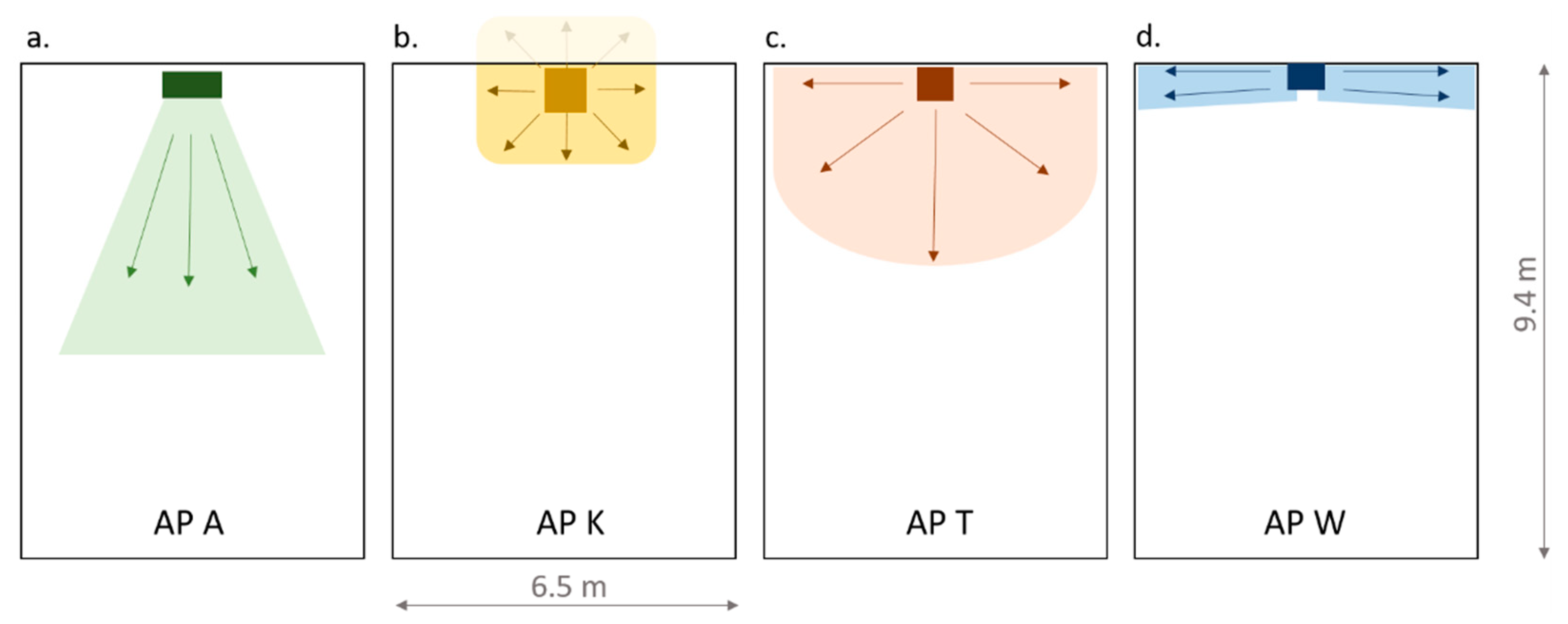
Figure 2. Illustration of the position of the investigated large APs within the classroom ((a). AP A, (b). AP K, (c). AP T, (d). AP W) including the qualitative flow direction at the outlet. Note: the length of the arrows and the marked area are intended to qualitatively represent the outlet direction and therefore they do not allow any conclusions to be drawn about the throw distance of the filtered air.
Atmosphere 14 01437 g002
Figure 3. Sketch of the classroom with tables and chairs and the locations of the large (L) APs as well as the small (S) devices according to Table 2, including the positions of 4 different measuring points (MP 1–4). The grey rectangles represent tables and the squares with grey contours represent chairs.
Atmosphere 14 01437 g003
Figure 4. Normalized aerosol number concentration profile measured at measurement point MP1 and MP2 in a 186.4 m3 classroom during operation of air cleaner (a). AP A; (b). AP T; (c). AP W with different AP volume flow settings. The markers (·, ×, Δ) indicate the measurement results, and the lines the regression function according to Equation (1).
Atmosphere 14 01437 g004
Figure 5. Time decay behavior of the particle number concentration when using portable air cleaners ((a). 4×AP P; (b). 3× AP X) at different operating levels as well as without air cleaners in a classroom (186 m3). The markers indicate the measurement results and the lines the regression function according to Equation (1).
Atmosphere 14 01437 g005
Figure 6. Normalized aerosol number concentration profile measured at measurement point MP1 and MP2 in a 186.4 m3 classroom during operation of air cleaner, (a). AP A; (b). AP T; (c). AP W at set volume flow 1000 m3/h with new prefilters and heap filters (0 a) and filters used for one year (1 a corresponds to 190 days of 8 h). The markers (·, ×, Δ) indicate the measurement results and the lines the regression function according to Equation (1).
Atmosphere 14 01437 g006
Table 1. Overview of studies on air cleaners (AP) in schools from different years and countries with different types of APs, all of which have HEPA filters.
Source/YearType of APCountryMeasurement Results
[37], 2017portable AP (HEPA)USPM2.5, black carbon (BC), noise level
[38], 2020not specifiedKoreaPM2.5, PM10, CO2
[39], 2021large AP (HEPA)Germanyparticle number concentration, particle size distribution
[40], 2021portable AP (HEPA)Germanyparticle number concentration, particle size distribution, PM10, CO2, noise level
[41], 20213 large APs (HEPA)Germanyparticle number concentration, particle size distribution, noise level
[42], 2023mobile AP (HEPA)Germanyparticle number concentration, air velocity, noise level
Table 2. Assignment of the different air cleaners to the set-up positions in the classroom according to Figure 3.
Type of APPosition of Air Cleaners
(L)(S1)(S2)(S3)(S4)
AP Ax
AP Kx
AP Tx
AP Wx
AP P xxxx
AP X xxx
Table 3. Decay rates, resulting CADRm (according to Equation (3)), efficiency ACEFs (Equation (4)), and time after 10% of initial particle number concentration is reached as well as A-weighted equivalent continuous sound level (LAeq) and power consumption (P) at different set volume flows of AP A, AP K, AP T, AP W.
Manufacturer’s InformationMeasured Values
AP LevelVolume Flow (m3/h)Decay Rate (λAP) in 1/ht(Ct/C0 = 0.1) in minCADRm
in m3/h
LAeq
in dB(A)
P in WACEFs
MP1MP2
AP A57904.284.2532.4776.433.585.800.98
610605.835.8323.71068.139.7158.701.01
6.511906.286.2322.11147.3--0.97
AP K100010004.124.1333.5752.748.7248.300.75
AP T8008004.724.6629.5855.635.167.301.07
100010005.895.8923.51079.340.7106.151.08
120012006.987.0019.81284.3--1.07
AP W46902.302.5157.4429.738.781.200.62
510003.613.7137.7663.643.2162.150.67
612004.944.9727.9905.0--0.76
Table 4. Decay rates determined by the measurement results (room volume 186.4 m3) at measuring points (MP) 1 and 2, the resulting CADRm, the measured (m) volume flow rate V ˙ , the efficiency ACEFm (Equation (5)), and time after 10% of initial particle number concentration is reached (Equation (3)), the power consumption of all (n) units used at the same time, A-weighted equivalent continuous sound levels (LAeq) measured at one unit and n units measured at a distance of 1 m at a height of 1.1 m for the portable air cleaners AP P and AP X.
LevelDecay Rate in 1/h
(Range in 1/h)
t(Ct/C0 = 0.1)
in min
CADRm
in m3/h
V ˙ m , n in m3/h LAeq,n = 1
in dB(A)
LAeq,n
in dB(A)
Power Consumption
(Pn) in W
ACEFm
MP 1MP2
AP P (n = 4)
12.35 (0.01)2.38 (0.13)58.4423.7-<30.032.122.4-
23.36 (0.08)3.45 (0.05)40.6617.561438.741.139.81.01
34.48 (0.18)4.53 (0.06)30.7822.685745.247.970.00.96
t6.58 (0.01)6.59 (0.08)21.01210.3128953.956.4174.90.94
AP X (n = 3)
42.36 (0.23)2.49 (0.09)57.0434.9-32.435.222.2-
63.12 (0.02)3.31 (0.03)43.0582.1-40.243.236.1-
83.55 (0.10)3.71 (0.02)38.1659.560642.145.148.21.09
124.94 (0.04)5.03 (0.03)27.7912.188549.652.596.51.03
176.31 (0.02)6.38 (0.01)21.81165.6113855.358.0168.41.02
Table 5. Decay rates determined by the measurement results (room volume 186.4 m3) at measuring points (MP) 1 and 2, the resulting CADRs, the ACEFs (Equation (4)), and time after 10% of initial particle number concentration is reached (Equation (3)), the power consumption and the A-weighted equivalent continuous sound levels (LAeq) measured at a distance of 1 m at a height of 1.1 m depending on the usage time of the prefilters and HEPA filters of the air cleaners AP A, AP T, and AP W when new (0 a) and after one year (1 a) (190 days of 8 h).
Usage Period in aMeasured Values
AP PrefilterHEPA FilterDecay Rate (λAP) in 1/ht(Ct/C0 = 0.1) in minCADRm in m3/hLAeq
in dB(A)
P in WACEFs
MP1MP2
AP A0 a0 a5.805.7523.91058.638.7158.71.00
0 a1 a5.505.5025.11007.6--0.95
1 a1 a3.863.8835.7703.938.6 (a)156.2 (a)0.66
AP T0 a0 a5.905.8723.51079.540.7106.21.08
0 a1 a5.945.8423.51080.940.6109.01.08
1 a1 a5.775.7324.01053.940.5122.01.05
AP W0 a0 a3.643.7037.6667.443.2162.20.67
0 a1 a3.423.8538.0660.2--0.66
1 a1 a3.143.3542.6587.444.6151.70.59
Note: (a): the values refer to a usage period of 3 months.
Disclaimer/Publisher’s Note: The statements, opinions and data contained in all publications are solely those of the individual author(s) and contributor(s) and not of MDPI and/or the editor(s). MDPI and/or the editor(s) disclaim responsibility for any injury to people or property resulting from any ideas, methods, instructions or products referred to in the content.