1. Introduction
In order to develop economies and improve people’s lives, most countries established agricultural or industrial systems and the supporting transportation nets. With the functioning of the above systems, series of pollutants were emitted into atmosphere, and then caused serious air pollution [
1]. All of the manmade sources of pollutants can be classified as transportation, solid waste disposal, and industrial process. Recent investigation reveals that transport activities are a major source towards emitting heavy pollutants found in the environment [
2]. Take China as an example. China’s motor vehicle ownership is on the rise year by year, and according to the China Mobile Source Environmental Management Annual Report (2021), the total number of motor vehicles in China had reached 372 million by the end of 2020. The vehicle emissions of carbon monoxide (CO), hydrocarbons (HC), nitrogen oxides (NOx), and particulate matter (PM) from diesel vehicles are 1.249 million tons, 196,000 tons, 5.449 million tons, and 64,000 tons, respectively, accounting for 18.0%, 11.4%, 88.8%, and more than 99% of total vehicles emissions. In addition, the influence of off-road machinery emissions on air quality cannot be ignored. To control the mobile resources pollutions effectively, China has established a whole set of strict emission regulations. For diesel-powered vehicles and machinery, it is difficult to meet the emission standard requirements by only improving fuel, oil, and in-engine purification technology, but the high-efficiency aftertreatment devices must be relied on. The main aftertreatment technologies for diesel engines are diesel oxidation catalyst (diesel oxidation catalyst, DOC), selective catalytic reduction device (selective catalytic reduction, SCR), diesel particulate filter (diesel particulate filter, DPF), etc.
Affected by many physical and chemical factors, the performance of diesel emission aftertreatment device will inevitably gradually lose their effectiveness in the process of their use, which may also adversely impact the dynamics of the diesel engine. Therefore, the emission standards require that the aftertreatment devices must maintain sufficient purification performance within a fairly long life (or mileage), which places high demands on the durability of the aftertreatment devices. So, when we develop an aftertreatment device or test its quality, not only the fresh sample, but also the aged sample should be evaluated. Aiming to provide an easy way for the researchers to have an overall understanding of this area, this paper summarized the main aging mechanisms and durability assessment methods.
2. Overview of Diesel Engine Aftertreatment Technology
Diesel engines operate with a much higher air–fuel ratio which has the advantage of a very high thermal efficiency. So, diesel engines can provide strong power output with relatively lower fuel consumption. However, it also leads to the emission of a large number of pollutants including CO, HC, NOx, and PM. Specifically, the emissions of NOx and PM are significantly higher than those of gasoline engines. Therefore, the purification of NOx and PM from diesel engines is particularly important, and the combined application of multiple aftertreatment technologies is required to ensure emission compliance after the implementation of more stringent emission standards. This section introduces the current mainstream diesel engine aftertreatment technologies, namely DOC, DPF, and SCR.
2.1. DOC
DOC can promote the purification of CO, HC, and the soluble organic fraction (SOF) of PM [
3] by catalyzing the oxidation reactions of them, and the conversion efficiency can reach roughly 80%, 80%, and 40% respectively. DOC can convert part of NO into NO
2 [
4], which contributes greatly to its subsequent purification. DOC were also often used in oxidating diesel to increase the exhaust temperature, so that the DPF can be regenerated successfully.
DOC generally consists of a honeycomb carrier, washcoat material, and metal shell. Usually, cordierite ceramic honeycomb is used as the carrier, and precious metals such as platinum (Pt) and palladium (Pd) are used as the main catalyst [
5,
6]. However, due to the insufficient surface of the dense ceramic material honeycomb, it is not suitable for dispersing the catalyst, so it is necessary to adhere highly specific surface area materials (e.g., alumina (Al
2O
3)) to the ceramic material, and then load the main catalyst on the washcoat [
7,
8]. Currently, DOC has been widely used to treat diesel exhaust.
The improvement of DOC technology is mainly through the optimization of the catalyst structure and materials to raise the efficiency of pollutant purification and reduce the temperature required for purification. It was found that the addition of an appropriate amount of polyvinyl alcohol (PVA) to the carrier enhances the particle size effect of the catalyst, significantly increases the maximum conversion of NO, and reduces the light-off temperature of the oxidation reaction of CO, HC, and NO by about 20 °C [
9]. The catalytic efficiency can also be significantly enhanced when Fe
2O
3 is used as the catalyst carrier [
10,
11].
2.2. DPF
In the past two decades, with the maturity of DPF technology, diesel PM emission pollution has been effectively controlled, and DPF has thus been proven to be the most effective technology to reduce PM emissions [
12,
13].
DPF has various structural forms, such as wound fiber, metal foam, wall-flow honeycomb, etc. Usually, ceramic-based materials are used as filtration materials, and current research and applications are mainly focused on wall-flow ceramic honeycomb filter bodies made of cordierite, alumina titanate, silicon carbide, mullite, etc. [
14]. The filter performance of DPF depends on its geometry (diameter, length, wall thickness, pore density, etc.) on a macroscopic level, and on the material properties of the substrate (microporous porosity and pore size, etc.) on a microscopic level. The variation of filtration efficiency and pressure drop were decided mainly by the gas flow rate and the concentration of particulate matter in the incoming gas stream [
15]. Recently, the application of asymmetric cell technology (ACT) on DPF has been gaining attention [
16]. The technique is to enlarge the inlet port and reduce the occlusion port of the DPF to form an asymmetric through-hole cell structure. By analyzing the pressure drop and temperature field characteristics of the ACT type DPF, it is found that the ACT type DPF has obvious advantages for application at higher soot load and higher engine speed, with very low pressure drop and more uniform particle concentration deposited along the axial direction [
17].
Since the continuous accumulation of PM will eventually block up the DPF, the trapped PM needs to be removed from the DPF to avoid excessive back pressure in the exhaust system, which will affect the normal operation of the diesel engine. This technique is called DPF regeneration. Regeneration technology is divided into active regeneration and passive regeneration. Active regeneration removes the carbon content from DPF by increasing the exhaust temperature at which the PM can burn up and disappear [
18]. Passive regeneration is the way to achieve continuous regeneration of DPF under the conventional exhaust temperature of diesel engine by lowering the ignition temperature of PM by means of catalyst [
19,
20]. The catalyst can be loaded on the DPF, or added into diesel as fuel additive, etc. The combination of active regeneration and passive regeneration is a technical solution to achieve the stable operation of DPF and reduce the energy consumption of the system, which is gradually becoming the mainstream application solution [
21].
2.3. SCR
SCR is a technology that uses a reducer to selectively convert exhaust NOx to N
2 by a catalyst under the conditions of an oxygen-rich environment of diesel exhaust. The reducers include ammonia (NH
3), hydrocarbon (HC), and hydrogen (H
2). Among them, NH
3 is used most widely. However, the gas NH
3 has a strong irritating odor, which makes it inconvenient to be applied directly to SCR reactions, and is not easy to transport and store. Therefore, the NH
3 required for the reaction is usually supplied by injecting aqueous urea fluid (DEF) into the exhaust system, with a mass fraction of 32.5% urea. After injection into the exhaust system, urea hydrolyzes and reacts with NOx in the exhaust gas according to the following reaction equation [
22]:
SCR catalysts mainly include two types: vanadium-based [
23] and molecular sieve [
24]. Among the vanadium-based catalysts, V
2O
5/WO
3-TiO
2 base metal oxide catalysts are the most common [
25]. Vanadium-based catalysts have the advantages of higher conversion efficiency, good durability, insensitivity to sulfur, and low cost [
26]. However, its thermal stability is poor. Furthermore, vanadium-based catalysts are prone to volatilize and emit V
2O
5 toxic gas at high temperature. Molecular sieve catalysts mainly include Cu molecular sieve and Fe molecular sieve catalysts, which are thermally stable and have a wide temperature window, but they are less resistant to sulfur and more costly.
3. Aftertreatment Device Aging Mechanism
The cleanup of diesel exhaust by aftertreatment units relies on both chemical and physical operating principles. DOC and SCR rely on catalytic chemical reactions that remove pollutants, and passive regeneration of DPFs also requires catalysts to reduce the temperature required for PM oxidation. DPF purifies PM by physical processes such as diffusion, interception, collision, and gravitational settling.
Catalysts such as DOC and SCR are important components of diesel engine emission aftertreatment units. However, during the operation of diesel vehicles or machinery, high temperature exhaust and certain harmful chemical components can cause catalyst performance degradation. The ash in the exhaust gas covering the catalyst surface can also hinder the catalytic reaction. Ash accumulation also causes non-renewable clogging of the DPF [
27]. Additionally, vibrations caused by engine operation can cause mechanical damage to the aftertreatment unit. [
28] All of the above phenomena lead to the decrease in aftertreatment device purification efficiency, or produce high exhaust resistance, which affects the normal operation of the diesel engine. These kinds of phenomena can be collectively referred to as aftertreatment device aging. This section introduces the main aging mechanisms of diesel aftertreatment unit, including thermal aging, catalyst poisoning, mechanical aging, ash clogging, etc.
3.1. Thermal Aging
Thermal aging refers to the degradation of catalyst purification efficiency due to the strong thermal environment of diesel exhaust [
29,
30]. The main causes of thermal aging include the following: aggregation of active components due to high temperature, changes in chemical composition and phase composition of catalyst, encapsulation of active components by the carrier, loss of active components due to volatilization, etc. [
31,
32].
The rate of the chemical reaction mostly increases with the increase in temperature. Vant Hoff’s law suggests that the rate of the reaction increases about 2–4 times for every 10 K increase in temperature. In 1889, Arrhenius proposed an empirical formula based on a large number of experiments, namely the following:
where
k is the chemical reaction rate constant,
T is the thermodynamic temperature,
Ea is the activation energy,
R is the molar gas constant, and
A is the finger front factor (frequency factor).
From the Arrhenius formula, the reaction rate constant is exponentially related to temperature, which is applicable to the primitive reaction and part of the total package reaction, and therefore can be intuitively used for the reaction of the thermal aging process.
After thermal aging, the surface adsorption capacity, surface acidic sites and cat-alytic ability of the catalyst will decrease at lower temperatures. At higher temperatures, the catalyst’s Bronsted acidic sites will be cut down [
33,
34]. The micropore structure is destroyed, and the specific surface area is reduced, which results in a decrease in activity [
35]. For vanadium-based catalysts containing vanadium oxides, high temperatures also cause them to volatilize [
36]. In addition to the loss of catalytic activity, the volatile gases are also more harmful to human health. The addition of some elements to the catalyst can enhance its heat resistance. For example, it was found that neodymium (Nd), Cerium (Ce), and Titanium (Ti) in the platinum-based catalyst can help the catalyst maintain its activity after thermal aging [
37,
38,
39]. Aside from high temperatures, the existence of water in the exhaust is another important factor in inducing catalyst aging [
40,
41,
42].
In addition to the aging of the catalytic purifier, a high temperature will also have an adverse impact on the DPF. In practice, the end of the DPF filter body usually deposits a large amount of PM, and the non-controlled thermal regeneration generates a high temperature, which can cause unrecoverable damage to the DPF [
43,
44].
3.2. Catalyst Poisoning
Catalyst poisoning is the loss of the activity of a catalyst caused by harmful substances in the exhaust gas. These sorts of substances can adsorb on the catalyst surface and block the catalyst micropores, reducing the chemisorption sites on the catalyst and changing its surface chemistry [
45], or react with the active center of the catalyst to make the catalyst fail. Some hazardous substances can react with catalysts and cause agglomeration of active groups. All of these phenomena can lead to catalyst deactivation. The common harmful elements that can cause the poisoning of diesel exhaust catalysts include sulfur, phosphorus, alkali metals, and alkaline earth metals, etc. [
46]. Nowadays, biodiesel is drawing more and more attention [
47,
48]. However, biodiesel fuel also contains some inorganic impurities such as alkali metals, phosphorus compounds, etc., and these impurities may deposit all through the whole-vehicle exhaust system during the combustion of large amounts of biodiesel [
49,
50]. Some inorganic elements may interact with the catalysts, thereby influencing their physicochemical properties and reactivity [
51,
52].
Overall, sulfur is a harmful element that has the greatest impact on exhaust catalysts, and although fuel quality standards in China have been tightened in recent years, and sulfur content limits have been greatly reduced, there is still a certain amount of sulfur in commercially available diesel fuel due to various factors such as crude oil quality and market management, and the sulfur content of some of the offending oils is even up to more than one hundred times the regulatory limit. The sulfur in lubricating oil will also be mixed into the cylinder combustion during the working process of the diesel engine. Sulfur is converted to sulfur dioxide after combustion, some of which can be converted to sulfate, which combines with active sites to reduce the pore volume and specific surface area of the catalyst. Copper or iron molecular sieve catalysts, on the other hand, can react directly with sulfate, rendering the catalyst inactive. The phosphorus content in lubricating oil, usually about 1%, is the main source of phosphorus in diesel exhaust [
53], and phosphorus combustion at high temperatures forms aluminum phosphate or pyrophosphate that adhere to the exhaust catalyst surface, preventing exhaust pollutants from coming into contact with the catalyst and causing a decrease in purification efficiency [
54,
55]. Vanadium-based SCR catalysts have high tolerance of elements such as phosphorus and sulfur [
56], but poor tolerance of alkali metals, whose toxicity is proportional to their alkalinity. Catalysts can react with alkali metals and cause agglomeration of active groups leading to catalyst deactivation [
57], but by studying the toxic effects of alkali metal salts on catalysts, the development of excellent catalysts with high tolerances of alkali metals is expected [
58].
So, the above two aging mechanisms explain how the exhaust condition, including physical and chemical factors, reduces the activity of aftertreatment devices by changing the constituent and construction of catalysts. To resist these kinds of aging effects, efforts should mainly be taken to improve the catalyst formula.
3.3. Mechanical Aging
Mechanical aging refers to the phenomenon that the aftertreatment device wears or breaks because of the shock and vibration. The work running of a diesel engine is a complex mechanical vibration process. There are multi-directional forces, and these forces will cause the vibration of the exhaust system through the conduction of the exhaust manifold, and then cause its fatigue damage in order to cut down the purification efficiency [
59].
The leakage was found on the exhaust pipe of a low-odd light truck, then it was found in the engine rotation frequency and the inherent frequency of the exhaust system coupling, which caused the resonance leading to the cracking of the aftertreatment phenomenon [
60]. In addition, the vehicle inherent frequency and wheel rotation imbalance caused by the excitation frequency close to the vehicle will cause low-frequency vibration, and long-term low-frequency vibration will cause mechanical strain on the aftertreatment device [
59]. There are also studies that show that, in the process of gradually increasing the speed of the vehicle, the intensity of vibration at the location of the exhaust system will increase significantly, obviously higher than other areas of the vehicle, which result in greater vibration and eventually affect the normal work of the exhaust system [
61].
3.4. Ash Clogging
Diesel exhaust ash mainly comes from fuel additives, lubricant additives, diesel engine parts wear, and exhaust system corrosion, etc. [
62]. Among these, lube oil additives are the primary source [
63]. The high pressure in the piston ring area of the diesel engine allows the lubricating oil to be sprayed into the cylinder in the form of atomization. During the combustion, the metal additives of oil can be converted into gas phase compounds, and then condense on the carbon particles during the engine exhaust stroke [
64]. After the ash leaves the engine in the form of nanoscale particles, they reunite together and flow into the aftertreatment devices. The main part of the ash deposits in the DPF pores, and cannot be removed by conventional regeneration techniques. Usually, ash deposits in the DPF form an ash layer on the surface of the filter wall and ash plugs at the end of the DPF inlet channel, and deposition on the surface of the filter wall results in a greater increase in DPF pressure drop than deposition at the end of the inlet channel, as well as a higher buildup density.
Analyzed by X-ray diffraction (XRD), the main components of the ash were CaSO
4, Zn
2Mg (PO
4)
2, Zn
3 (PO
4)
2, MgO and MgSO
4 sulphates, phosphates and oxides of calcium, magnesium, and zinc [
65,
66]. The accumulation of ash is proportional to the consumption of lubricating oil. The more the lubricating oil is consumed, the greater the accumulation of ash, and then the greater the exhaust back pressure of the diesel engine, which in turn leads to higher fuel consumption and lowers power of the diesel engine, eventually causing the diesel engine to shut down.
Although DPF can effectively reduce particulate emissions and convert most PM into CO
2 through regeneration, studies have shown that ash cannot be burned and will remain in the DPF. A large amount of ash deposits at the end of the DPF orifice, forming an ash plug, which reduces the DPF filtration area and causes engine back pressure to rise [
67]. At the same time, ash will also have an adverse impact on the normal regeneration of DPF by chancing the pressure drop characteristics of the DPF, leading to passive regeneration errors and increasing the active regeneration frequency and regeneration temperature [
68].
Both mechanical aging and ash clogging affect the purifying caused by macroscopical phenomena. These kinds of aging can be overcome by improving the aftertreatment devices manufacturing technologies, engine technologies, and fuel quality.
4. Durability Assessment Method
Because the pollutant emission limits of emission standards are tightened step by step, diesel-powered vehicles and off-road machinery need to adopt DOC + DPF + SCR or similar comprehensive purification technology routes to meet the requirements of the standards. At the same time, with the continuous improvement of durability requirements, the accurate durability assessment method of the aftertreatment device becomes more and more important. For heavy-duty diesel vehicles, the national VI standard durability test requires that the aftertreatment device must be run with the vehicle up to at least 100,000 km, or be run on the bench for more than thousands of hours, which requires a lot of manpower, financial, and material resources. Therefore, the rapid assessment method for the durability of the aftertreatment device has been a hot spot.
4.1. Small Sample Aging Method
Small sample aging is mainly a thermal aging method for catalysts, in which small-sized catalyst samples in the reactor are fed with diesel exhaust or simulated exhaust gas, and heated in a controlled manner to achieve rapid aging [
69,
70,
71].
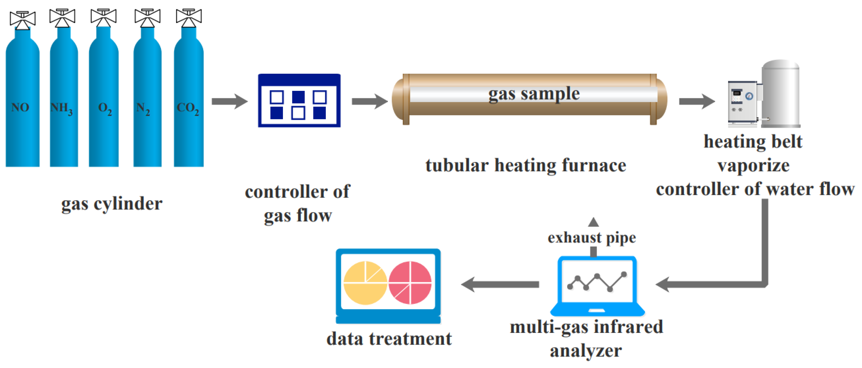
Figure 1 shows the structure of a small-sample rapid aging system [
72]. The system consists of a gas distribution unit, a tubular heating furnace, a water injection device, an aging reactor, a gas analyzer, and a main control computer. The system can regulate the gas flow rate, composition, catalyst temperature, and water vapor concentration to simulate different aging scenarios, and control the aging rate of catalyst samples by increasing the heating temperature and water vapor content. Di Wang et al. used such an aging system to rapidly age vanadium-based SCR catalysts at 600 °C for 50 h. The active temperature range of the aged catalyst changed from 200–530 °C to 210–480 °C, which means a reduction of about 18%, and is equivalent to thousands of hours of aging under actual exhaust conditions.
Deepak Kunwar et al. [
73] used a similar method to rapidly age DOC catalysts at 800 °C for 50 h, and achieved aging results similar to those of a vehicle running for 150,000 km under real conditions.
Schmieg et al. [
74] conducted aging tests on small samples of catalysts at different levels by simulating gas distribution, and found that 800 °C for 16 h is approximately equivalent to the aging effect of 135,000 miles.
The small-sample aging method enables the accelerated aging of catalyst samples at a very low cost, providing a viable operational solution for the rapid screening of catalyst formulations or mass characterization of samples for durability advantages and disadvantages. However, due to the large size difference between the small sample and the real product, as well as the relatively static test conditions, the aging test results may differ significantly from the actual application of the catalyst product, which needs to be determined by subsequent tests.
4.2. Whole-Vehicle Experimental Aging Method
The whole vehicle test is to run vehicles equipped with aftertreatment devices on the road, or chassis dynamometer to achieve the exhaust aftertreatment device performance deterioration [
75]. The vehicle should be run according to national standards. There are several kinds of running procedures described in the standards, and the test vehicle should be run according to these procedure at a minimum mileage. During the test, exhaust pollutants were tested periodically to judge whether the aftertreatment devices retained enough purification performance.
Yunhua Zhang et al. [
76] conducted emission analyses of a bus lasting one year, and found that the activity of DOC decreased significantly, with a 46.2% decrease in CO purification and a 33.8% decrease in HC purification. Characterization tests showed the decreases attributed to the thermal aging of DOC, i.e., sintering of the carrier coating and reduction in the specific surface area of the catalyst. The NOx and PM purification ratio were almost unchanged during aging, reflecting the good durability of the CCRT (catalyzed continuously regenerating trap) for PM and NOx purification in the exhaust system.
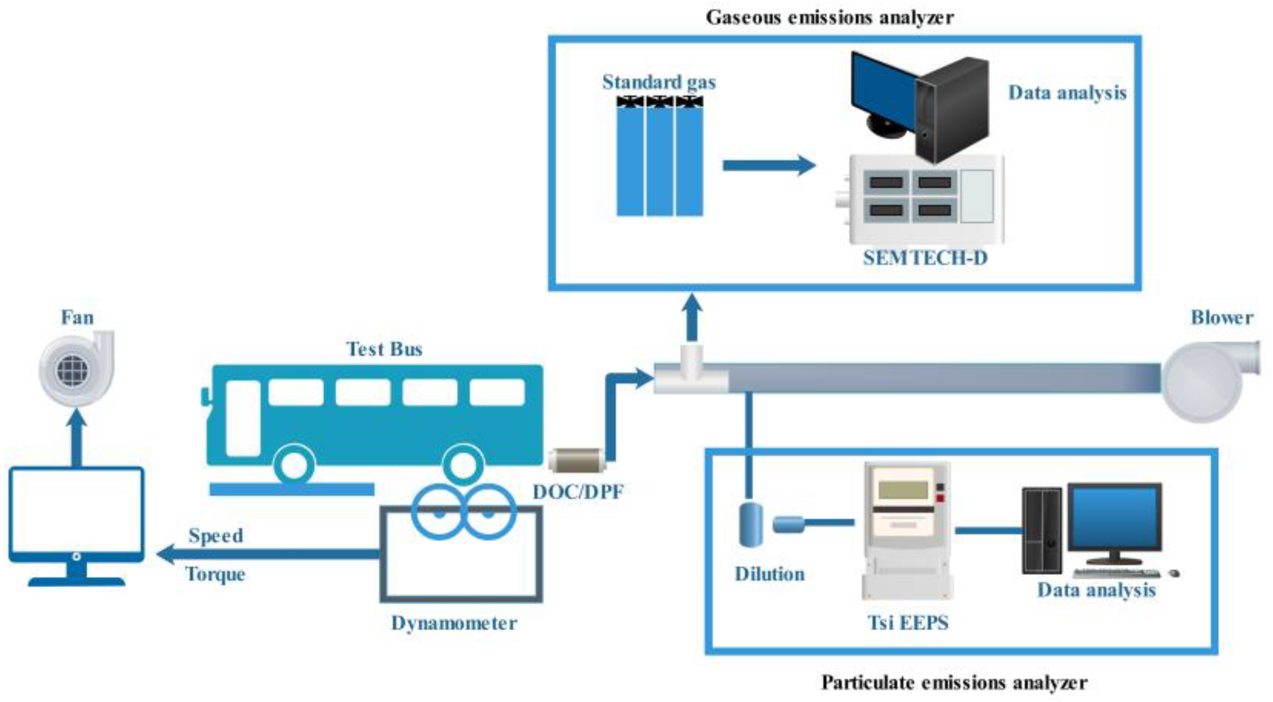
Figure 2 [
76] shows the structure of the whole-vehicle experimental aging method.
Dominik Rose [
77] conducted a set of durability tests on aftertreatment devices by running cars. The mixed driving cycle used in this research is described in
Table 1. After a long period of aging course, they found that the PM purifying performances of the DPFs changed just a little. That means the DPFs made of aluminum titanate have pretty good durability. Additionally, an ideal way to develop a running cycle is by uniting several running conditions.
There are a few vehicle-aging cycles normalized by emissions standards [
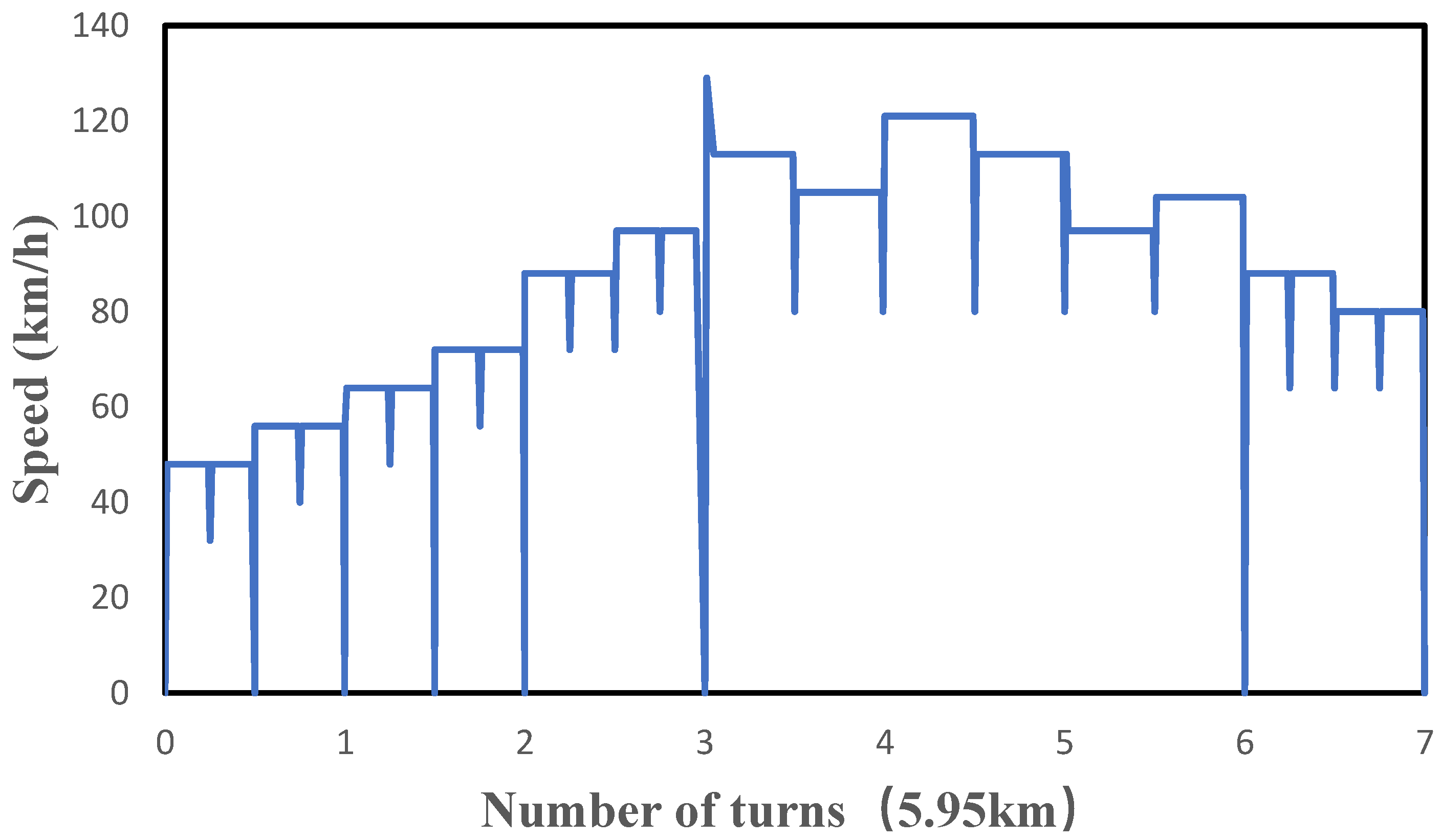
78]. Among them, the AMA and SRC are the most important ones used in the aftertreatment devices aging research works. Every AMA cycle includes 11 running cycles, and the distance of each running cycle is 6 km. The highest speed of each running cycle is listed in
Table 2.
Figure 3 shows the standard road cycle operating conditions used for the emission durability assessment of light-duty vehicles, as specified in GB18352-2016.
A P walker used another aging cycle, CEC L-52-T-97 [
80], which comprises a 400 h total cycle made up of four sequences of a 100 h cycle. The 100 h cycle is itself split into two sections of 50 h each, comprising a transient phase followed by a steady state phase. In Homayoun’s research [
81], they compared the catalysts aged by SRC cycle with samples aged by the small-sample aging method and the engine bench aging method, finding the reactivities of the former samples were a little lower the others. Here, the SRC cycle acts as a reference to judge the other methods.
The whole-vehicle test aging method is closest to the actual aging condition in the process of vehicle running, and the test results are the most reliable. However, this method requires the running of the vehicle for more than 100,000 km on the road or bench, occupying a lot of test equipment or sites, consuming a lot of fuel and accessories, lasting a long time, and requiring a lot of experimental personnel. The comprehensive cost is much higher than other aging methods. So, it should not be used far and wide, but to operate only in some situations with high accuracy demands and very sufficient test conditions.
4.3. Engine Bench Test Aging Method
Engine bench aging is also a common method to evaluate the durability of diesel exhaust aftertreatment devices. The test system consists of a diesel engine, engine dynamometer, and emission testing instrument units, etc. The performance of the emission aftertreatment device gradually decreases during the operation of the diesel engine, which is subjected to a durability test.
Figure 4 [
82] shows the typical test system composition of engine machine bench aging.
The operating conditions of diesel engines are the key to determining the aftertreatment of this method. According to the requirements of GB17691-2018 standard, the durability test method can be adjusted based on the ratio of typical in-use vehicle fuel consumption and aging cycle fuel consumption to achieve fast aging, but the fuel consumption of the aging cycle cannot exceed 30% of typical in-use vehicle fuel consumption. An engine bench test cycle provided in standard GB20890-2007 described a running cycle, and an engine should be run in accordance with the cycle for 5 h to correspond to similar aftertreatment device aging degrees caused by 800 km of vehicle running. So, the cycle greatly reduces the test time and cost.
Table 3 shows the specific operation steps of this operation cycle.
Pi-qiang Tan et al. [
83]. investigated the durability of the aftertreatment devices equipped on a heavy-duty diesel engine using mixed fuels by engine bench test. The aftertreatment unit consisted of DOC and SCR, and the whole engine durability test was operated according to GB20890-2007 standard. After 100 cycles of aging, the overall purification performance of the SCR decreased by about 7.5%, and this purification efficiency decreased with increasing engine speed.
Qiao et al. [
84] used the engine bench to age two SCR catalysts. The engine exhaust temperature, NH
3/NOx ratio, and running time were 550 °C, 0.8, and 200 h respectively. It can be seen from the results that these aging conditions equal the aging effect of 200,000 kilometer’s worth of real road running.
The engine bench test aging method is widely used for the performance evaluation and analysis of various aftertreatment devices because of its advantages in accurate process control, intuitive data for easy analysis, and relatively low cost. Additionally, this kind of method can reduce the deviations of aging results derived from the changes of the test conditions in the long-term road-running aging test. The disadvantage is that the engine operating conditions are formed by summarizing the key parameters of diesel engines in the process of diesel vehicles road driving or the operation of non-road machinery, as well as the type of vehicles or non-road machinery selected. The operation process and calculation methods may cause errors in the formed diesel engine operating conditions, thus leading to the existence of a certain deviation between the test aging results of exhaust aftertreatment devices and the actual aging effects in the process of vehicle driving or machinery operation.
4.4. Burner Experimental Aging Method
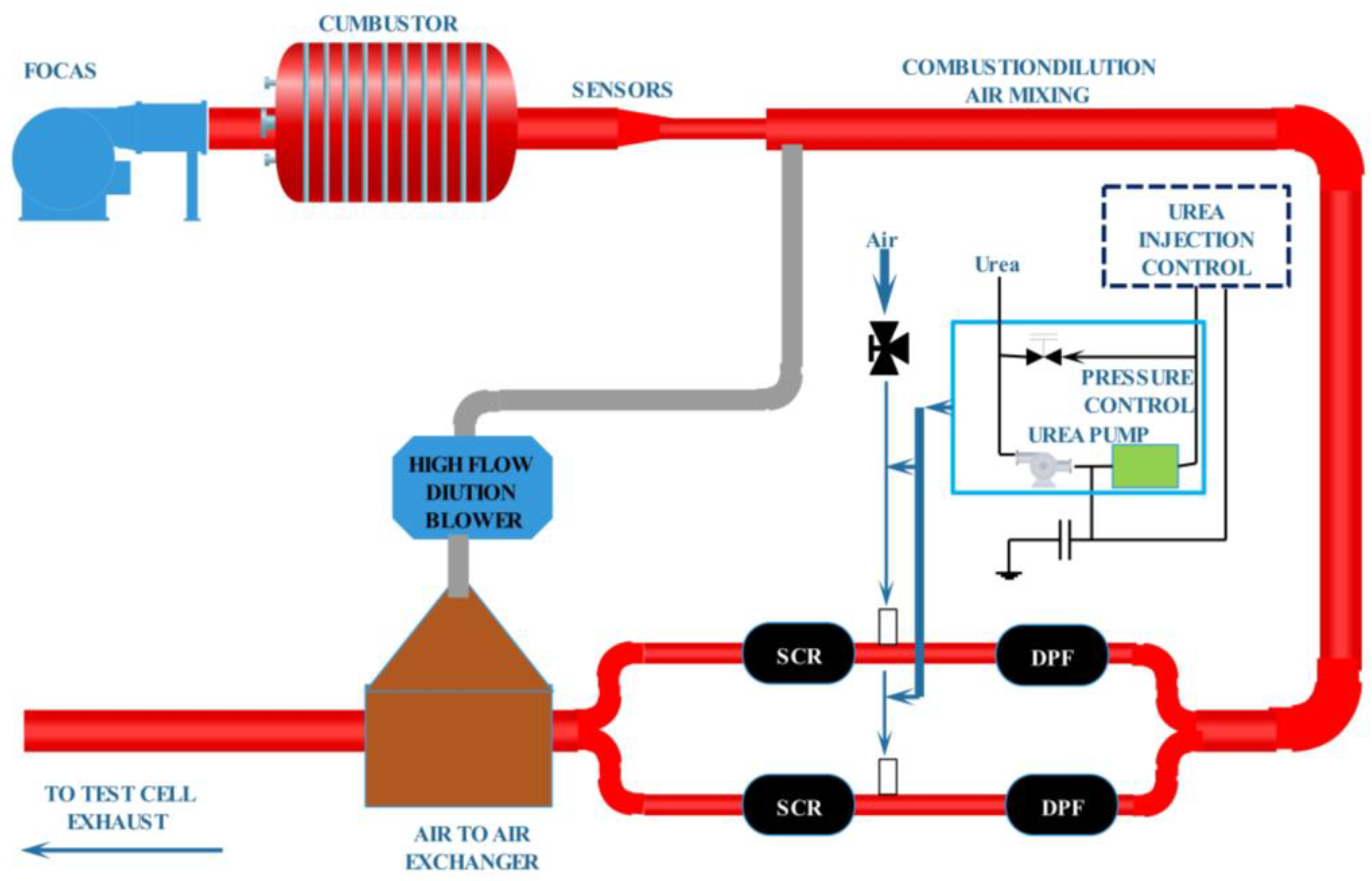
Although the cost is reduced compared to the whole-vehicle test aging method, the engine bench aging test also needs a lot of test equipment and consumes a large amount of fuel; thus, engine bench aging is also comparatively costly. For these kinds of reasons, Southwest Research Institute has developed a Fuel Oil Catalyst Aging System (FOCAS) that simulates engine aging conditions. The fuel consumption of this system is very low, so it can reduce the test cost greatly. At the same time, the burner aging method can be used for aging all types of common aftertreatment devices.
Webb C et al. [
85]. verified the reliability of the burner aging method. The burner system used in the test consists of a fan, oil supply system, combustion chamber, vortex mixing section, and high-flow dilution system, as shown in
Figure 5. The system can control the gas temperature and gas flow accurately to create an aging environment. The system was used to age the diesel exhaust aftertreatment unit for 100 h and the results were compared with the engine bench aging test, which proved that the burner aging system can achieve the aging of the aftertreatment system using lower fuel consumption.
Sonntag F et al. [
86] used burners for fast-loading ash tests at a low cost and achieved better results. The burner system can be parametrically controlled and has a high degree of flexibility.
The burner aging method provides a way to generate high temperature exhaust aging conditions at low oil consumption and independently control exhaust flow, temperature, and component concentration, as well as to inject oil to produce large amounts of ash for rapid aging of DPF. However, on earth the combustions of combustor and diesel engine are far more different, so there must be some differences between the exhaust conditions of the two devices. Additionally, the differences may induce the deviations of aging results to some extent. So, before being chosen as an accurate evaluating method, more efforts should be invested to improve it.
4.5. Accelerated Ash Plugging Aging Method
Unlike SCR and DOC, which achieve pollution purification through catalytic reactions, DPF achieves PM purification through physical processes such as collision and interception. The ash deposited in the DPF during the purification process cannot be regenerated and removed. So, the accumulated ash is an important reason for the degradation of the DPF performance. Therefore, the aging process of DPF can be simulated by using a specific method to realize the accumulation of a large amount of ash within DPF in a short period.
By analyzing the various ways in which the lubricant enters the combustion chamber and the subsequent combustion process, three methods of rapid-aging evaluation of ash plugging were derived as follows: blending the lubricant into the fuel, increasing the diesel engine load, and spraying the lubricant mist into the intake manifold to achieve an increased lubricant-consumption rate. Maintaining the diesel engine operating under high load conditions affects the experimental accuracy by excessive diesel engine losses, and the method of blending lubricating oil into the fuel is simple to operate and has more application examples.
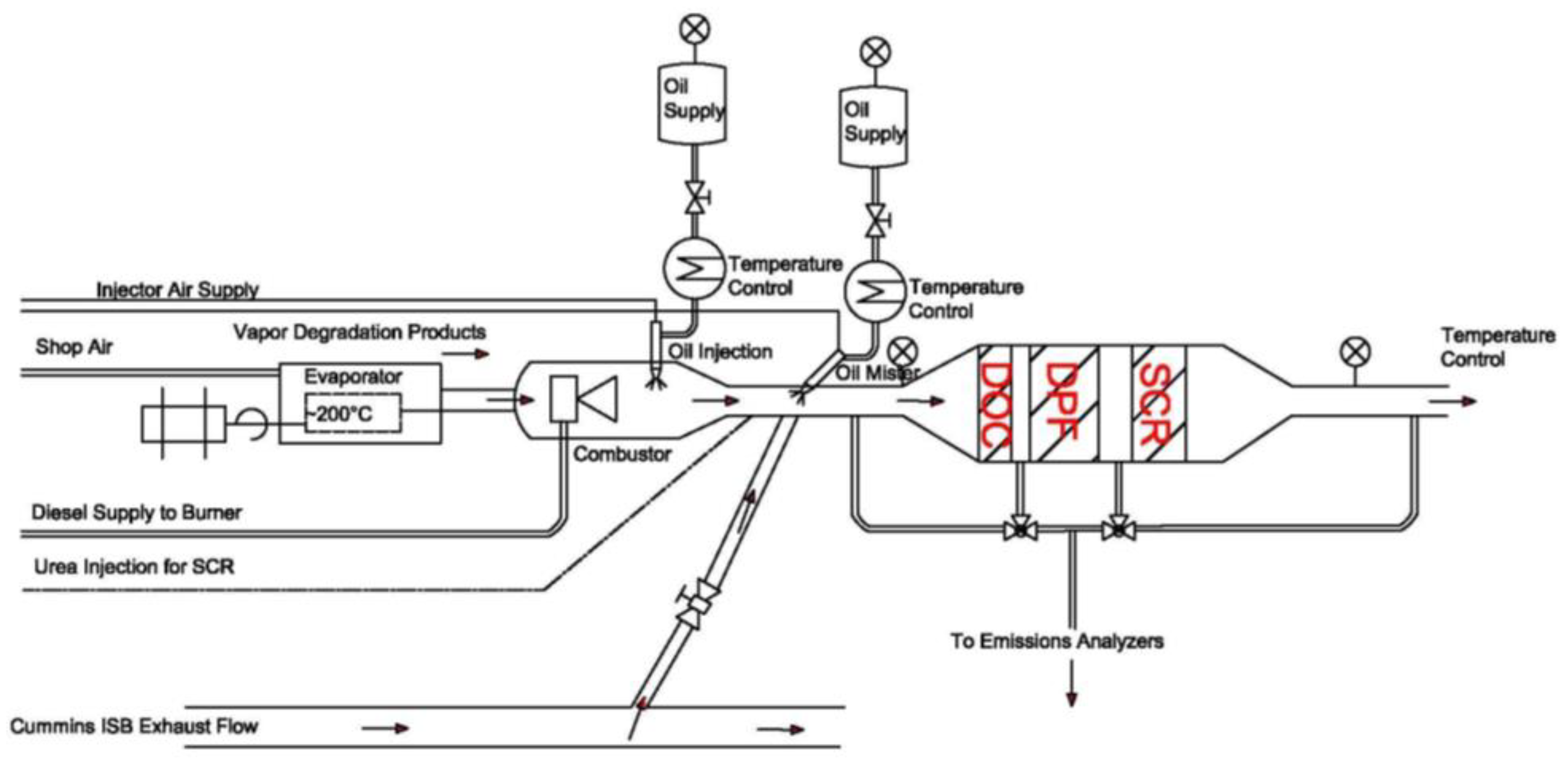
Figure 6 [
87] shows the lubricating oil injection system. The lubricating oil is atomized through the heating system, and there is a measuring device in the lubricating oil tank, which can monitor the consumption of lubricating oil in real time. the atomized lubricating oil is sprayed into the intake manifold through the injector, and then into the combuster, to achieve the aging effect of the rapid accumulation of ash.
Youngquist et al. [
88] added lubricating oil to diesel. When the consumption of lubricating oil was about 50 times that of normal lubricating oil, the 60 h experiment simulated the normal oil consumption during about 140,000 km of vehicle running, greatly reducing the time and cost required for DPF durability assessment. Sappok Alexander G et al. [
87] also used the method of mixing lubricating oil in diesel to rapidly age the DPF, and quickly loaded two DPFs to 40 (g/L) within 10 h, realizing equivalent aging of 482,000 km of vehicle running.
All those studies show that the method of mixing lubricating oil in diesel can easily and quickly realize the large amount of ash deposition in DPF, which simulates its performance aging. So, this method is cheap and easy to operate. However, in order to accurately control the amount of lubricating oil added in diesel, it is necessary to accurately measure the consumption rate of lubricating oil in an actual vehicle or machinery operation as the basis for calculation.
Some studies also show that the physical properties of the ash deposited by the above three acceleration methods are different from those deposited during actual vehicle driving or non-road machinery operation, so the impact on DPF performance is also slightly different. In the follow-up study, additional tests are needed to determine the extent and reason for the difference, so as to improve the accuracy of durability simulation assessment.
5. Conclusions
Diesel exhaust pollutants are complex and require multiple types of aftertreatment technology such as DOC, DPF, and SCR to work together to achieve good purifying results. As far as the aftertreatment device aging mechanism and their durability assessment method, there are several conclusions that can be drawn from the materials above.
The working principles and structures of various aftertreatment devices are different, and their performance degradation principles can be roughly divided into thermal aging, catalyst poisoning, mechanical aging, ash clogging, etc.
As to thermal aging and catalyst poisoning, they mainly reduce the activity of aftertreatment devices by changing the constituent and construction of catalysts. To resist these kinds of agings, efforts should mainly be taken to improve the catalyst formula.
With regard to mechanical aging and ash clogging, they affect the purifying cause by macroscopical phenomena. These kinds of aging can be overcome by improving the aftertreatment devices manufacturing technologies, engine technologies, and fuel quality.
To accurately evaluate the durability of the aftertreatment device, the common methods include small sample aging, vehicle test aging, engine bench test aging, burner test aging, etc.
The speed of small-sample aging is fastest and the cost is lowest, which is suitable for screening a large number of samples in the process of technology development. However, the aging test results may differ significantly from the actual aftertreatment catalyst.
The results of the whole vehicle test method are most close to the reality, but it takes too much time and is too expensive. It is only applicable to the experimental finalization, but cannot be used widely.
Compared with the vehicle test method, the engine bench test has reduced the cost in all aspects, and has been stipulated by the national standard as the durability assessment method of aftertreatment devices.
The burner aging method provides a low-cost way to evaluate the durability of the aftertreatment device. However, before being chosen as an accurate evaluating method, more efforts should be invested in improving it.
Author Contributions
Conceptualization, K.L. and Y.W.; methodology, T.Y.; software, T.Y.; validation, Q.W., P.Y. and J.K.; formal analysis, B.W.; investigation, P.Y.; resources, Q.W.; data curation, K.L.; writing—original draft preparation, T.Y.; writing—review and editing, K.L.; visualization, T.Y.; supervision, B.W.; project administration, Q.W.; funding acquisition, J.K. All authors have read and agreed to the published version of the manuscript.
Funding
This research was funded by the Fundamental Research Funds for the Central Public-interest Scientific Institution (grant no. YSKY2020-001) and the National Key R&D Program of China (grant no. 2017YFC02111205).
Institutional Review Board Statement
Not applicable.
Informed Consent Statement
Not applicable.
Data Availability Statement
Not applicable.
Acknowledgments
The authors would like to thank the editors and anonymous reviewers for their suggestions to improve this article.
Conflicts of Interest
The authors declare no conflict of interest.
References
- Xu, G.; Shan, W.; Yu, Y.; Shan, Y.; Wu, X.; Wu, Y.; Zhang, S.; He, L.; Shuai, S.; Pang, H.; et al. Advances in emission control of diesel vehicles in China. J. Environ. Sci. 2021, 123, 15–29. [Google Scholar] [CrossRef] [PubMed]
- Zhang, C.; Li, Z.; Wang, Y.; Wang, Y.; Fan, R.; Ding, Z. Development of catalytic technology and integrated system for diesel vehicle aftertreatment. Met. Funct. Mater. 2020, 27, 20–27. [Google Scholar] [CrossRef]
- Khobragade, R.; Saravanan, G.; Einaga, H.; Nagashima, H.; Shukla, P.; Gupta, T.; Agarwal, A.K.; Labhasetwar, N. Diesel fuel particulate emission control using low-cost catalytic materials. Fuel 2021, 302, 121157. [Google Scholar] [CrossRef]
- Buzková Arvajová, A.; Boutikos, P.; Kočí, P. Differentiation between O2 and NO2 impact on PtOx formation in a diesel oxidation catalyst. Chem. Eng. Sci. 2019, 195, 179–184. [Google Scholar] [CrossRef]
- Shukla, P.C.; Gupta, T.; Labhasetwar, N.K.; Khobaragade, R.; Gupta, N.K.; Agarwal, A.K. Effectiveness of non-noble metal based diesel oxidation catalysts on particle number emissions from diesel and biodiesel exhaust. Sci. Total Environ. 2017, 574, 1512–1520. [Google Scholar] [CrossRef] [PubMed]
- Liu, J.; Ding, T.; Zhang, H.; Li, G.; Cai, J.; Zhao, D.; Tian, Y.; Xian, H.; Bai, X.; Li, X. Engineering surface defects and metal–support interactions on Pt/TiO2 (B) nanobelts to boost the catalytic oxidation of CO. Catal. Sci. Technol. 2018, 8, 4934–4944. [Google Scholar] [CrossRef]
- Kang, S.B.; Kalamaras, C.; Balakotaiah, V.; Epling, W. Zoning and Trapping Effects on CO and Hydrocarbon Light-Off in Diesel Oxidation Catalysts. Ind. Eng. Chem. Res. 2017, 56, 13628–13633. [Google Scholar] [CrossRef]
- Zhang, J.; Lou, D.; Sun, Y.; Tan, P.; Hu, Z.; Huang, C. Effects of DOC and CDPF Catalyst Composition on Emission Characteristics of Light-Duty Diesel Engine with DOC + CDPF + SCR System; SAE International by University of Birmingham: Warrendale, PA, USA, 2018; Volume 1, p. 3317. [Google Scholar] [CrossRef]
- Liang, Y.; Ding, X.; Wang, J.; Zhao, M.; Dan, Y.; Jiang, L.; Chen, Y. Catalytic performance promoted on Pt-based diesel oxidation catalyst assisted by polyvinyl alcohol. Environ. Sci. Pollut. Res. 2020, 27, 41824–41838. [Google Scholar] [CrossRef] [PubMed]
- Resitoglu, I.A.; Altinisik, K.; Keskin, A.; Ocakoglu, K. The effects of Fe2O3 based DOC and SCR catalyst on the exhaust emissions of diesel engines. Fuel 2020, 262, 116501. [Google Scholar] [CrossRef]
- Yang, Z.; Zhang, N.; Cao, Y.; Li, Y.; Liao, Y.; Li, Y.; Gong, M.; Chen, Y. Promotional effect of lanthana on the high-temperature thermal stability of Pt/TiO2 sulfur-resistant diesel oxidation catalysts. RSC Adv. 2017, 7, 19318–19329. [Google Scholar] [CrossRef]
- Guan, B.; Zhan, R.; Lin, H.; Huang, Z. Review of the state-of-the-art of exhaust particulate filter technology in internal combustion engines. J. Environ. Manag. 2015, 154, 225–258. [Google Scholar] [CrossRef] [PubMed]
- Haugen, M.J.; Bishop, G.A. Long-Term Fuel-Specific NOx and Particle Emission Trends for In-Use Heavy-Duty Vehicles in California. Environ. Sci. Technol. 2018, 52, 6070–6076. [Google Scholar] [CrossRef] [PubMed]
- Benaqqa, C.; Gomina, M.; Beurotte, A.; Boussuge, M.; Delattre, B.; Pajot, K.; Pawlak, E.; Rodrigues, F. Morphology, physical, thermal and mechanical properties of the constitutive materials of diesel particulate filters. Appl. Therm. Eng. 2014, 62, 599–606. [Google Scholar] [CrossRef]
- Orihuela, M.P.; Chacartegui, R.; Gómez-Martín, A.; Ramírez-Rico, J.; Villanueva, J.A.B. Performance trends in wall-flow diesel particulate filters: Comparative analysis of their filtration efficiency and pressure drop. J. Clean. Prod. 2020, 260, 120863. [Google Scholar] [CrossRef]
- Xiao, G.; Li, B.; Tian, H.; Leng, X.; Long, W. Numerical study on flow and pressure drop characteristics of a novel type asymmetric wall-flow diesel particulate filter. Fuel 2020, 267, 117148. [Google Scholar] [CrossRef]
- Watling, T.C. Flow and forced convection heat transfer characteristics of developed laminar flow in the octahedral channels of octo-square asymmetric particulate filters. Results Eng. 2020, 5, 100086. [Google Scholar] [CrossRef]
- R’Mili, B.; Boréave, A.; Meme, A.; Vernoux, P.; Leblanc, M.; Noël, L.; Raux, S.; D’Anna, B. Physico-Chemical Characterization of Fine and Ultrafine Particles Emitted during Diesel Particulate Filter Active Regeneration of Euro5 Diesel Vehicles. Environ. Sci. Technol 2018, 52, 3312–3319. [Google Scholar] [CrossRef]
- Smith, J.D.; Ruehl, C.; Burnitzki, M.; Sobieralski, W.; Ianni, R.; Quiros, D.; Hu, S.; Chernich, D.; Collins, J.; Huai, T.; et al. Real-time particulate emissions rates from active and passive heavy-duty diesel particulate filter regeneration. Sci. Total Environ. 2019, 680, 132–139. [Google Scholar] [CrossRef]
- Luo, S.; Wu, X.; Jin, B.; Liu, S.; Ran, R.; Si, Z.; Weng, D. Size effect of Pt nanoparticles in acid-assisted soot oxidation in the presence of NO. J. Environ. Sci. 2020, 94, 64–71. [Google Scholar] [CrossRef]
- Ding, X.; Liang, Y.; Zhang, H.; Zhao, M.; Wang, J.; Chen, Y. Preparation of Reduced Pt-Based Catalysts with High Dispersion and Their Catalytic Performances for NO Oxidation. Acta Phys. -Chim. Sin. 2022, 38, 2005009. [Google Scholar] [CrossRef]
- Han, L.; Cai, S.; Gao, M.; Hasegawa, J.-Y.; Wang, P.; Zhang, J.; Shi, L.; Zhang, D. Selective Catalytic Reduction of NO(x) with NH(3) by Using Novel Catalysts: State of the Art and Future Prospects. Chem. Rev. 2019, 119, 10916–10976. [Google Scholar] [CrossRef] [PubMed]
- Hess, C.; Waleska, P.; Ratzka, M.; Janssens, T.V.W.; Rasmussen, S.B.; Beato, P. Hierarchical Vanadia Model Catalysts for Ammonia Selective Catalytic Reduction. Top. Catal. 2017, 60, 1631–1640. [Google Scholar] [CrossRef]
- Jiang, H.; Guan, B.; Peng, X.; Zhan, R.; Lin, H.; Huang, Z. Influence of synthesis method on catalytic properties and hydrothermal stability of Cu/SSZ-13 for NH3-SCR reaction. Chem. Eng. J. 2020, 379, 122358. [Google Scholar] [CrossRef]
- Mohan, S.; Dinesha, P.; Kumar, S. NOx reduction behaviour in copper zeolite catalysts for ammonia SCR systems: A review. Chem. Eng. J. 2020, 384, 123253. [Google Scholar] [CrossRef]
- Fan, C.; Chen, Z.; Pang, L.; Ming, S.; Zhang, X.; Albert, K.B.; Liu, P.; Chen, H.; Li, T. The influence of Si/Al ratio on the catalytic property and hydrothermal stability of Cu-SSZ-13 catalysts for NH3-SCR. Appl. Catal. A Gen. 2018, 550, 256–265. [Google Scholar] [CrossRef]
- Wang, Y.; Kamp, C.J.; Wang, Y.; Toops, T.J.; Su, C.; Wang, R.; Gong, J.; Wong, V.W. The origin, transport, and evolution of ash in engine particulate filters. Appl. Energy 2020, 263, 114631. [Google Scholar] [CrossRef]
- Chen, T.; Wu, Z.; Gong, J.; E, J.-Q. Numerical Simulation of Diesel Particulate Filter Regeneration Considering Ash Deposit. Flow Turbul. Combust. 2016, 97, 849–864. [Google Scholar] [CrossRef]
- Casapu, M.; Grunwaldt, J.-D.; Maciejewski, M.; Baiker, A.; Wittrock, M.; Gobel, U.; Eckhoff, S. Thermal ageing phenomena and strategies towards reactivation of NOx - storage catalysts. Top. Catal. 2007, 42–43, 3–7. [Google Scholar] [CrossRef]
- Park, J.-H.; Park, H.J.; Baik, J.H.; Nam, I.-S.; Shin, C.-H.; Lee, J.-H.; Cho, B.K.; Oh, S.H. Hydrothermal stability of CuZSM5 catalyst in reducing NO by NH3 for the urea selective catalytic reduction process. J. Catal. 2006, 240, 47–57. [Google Scholar] [CrossRef]
- Xu, H.; Liu, S.; Wang, Y.; Lin, Q.; Lin, C.; Lan, L.; Wang, Q.; Chen, Y. Promotional effect of Al2O3 on WO3/CeO2-ZrO2 monolithic catalyst for selective catalytic reduction of nitrogen oxides with ammonia after hydrothermal aging treatment. Appl. Surf. Sci. 2018, 427, 656–669. [Google Scholar] [CrossRef]
- Zhang, Y.; Lou, D.; Tan, P.; Hu, Z. Experimental study on the particulate matter and nitrogenous compounds from diesel engine retrofitted with DOC + CDPF + SCR. Atmos. Environ. 2018, 177, 45–53. [Google Scholar] [CrossRef]
- Daya, R.; Desai, C.; Vernham, B. Development and Validation of a Two-Site Kinetic Model for NH3-SCR over Cu-SSZ-13. Part 1. Detailed Global Kinetics Development Based on Mechanistic Considerations. Emiss. Control. Sci. Technol. 2018, 4, 143–171. [Google Scholar] [CrossRef]
- Gao, F.; Washton, N.M.; Wang, Y.; Kollár, M.; Szanyi, J.; Peden, C.H.F. Effects of Si/Al ratio on Cu/SSZ-13 NH3-SCR catalysts: Implications for the active Cu species and the roles of Brønsted acidity. J. Catal. 2015, 331, 25–38. [Google Scholar] [CrossRef]
- Heo, I.; Schmieg, S.J.; Oh, S.H.; Li, W.; Peden, C.H.F.; Kim, C.H.; Szanyi, J. Improved thermal stability of a copper-containing ceria-based catalyst for low temperature CO oxidation under simulated diesel exhaust conditions. Catal. Sci. Technol. 2018, 8, 1383–1394. [Google Scholar] [CrossRef]
- Leistner, K.; Kumar, A.; Kamasamudram, K.; Olsson, L. Mechanistic study of hydrothermally aged Cu/SSZ-13 catalysts for ammonia-SCR. Catal. Today 2018, 307, 55–64. [Google Scholar] [CrossRef]
- Kim, D.H.; Park, Y.J.; Lee, K.-Y.; Ha, H.P.; Kwon, D.W. Thermal stability of CeVO4-based catalysts depending on support composition for the selective catalytic reduction of NOx by ammonia. Res. Chem. Intermed. 2022, 48, 647–667. [Google Scholar] [CrossRef]
- Fan, J.; Ning, P.; Wang, Y.; Song, Z.; Liu, X.; Wang, H.; Wang, J.; Wang, L.; Zhang, Q. Significant promoting effect of Ce or La on the hydrothermal stability of Cu-SAPO-34 catalyst for NH3-SCR reaction. Chem. Eng. J. 2019, 369, 908–919. [Google Scholar] [CrossRef]
- Li, Y.; Song, W.; Liu, J.; Zhao, Z.; Gao, M.; Wei, Y.; Wang, Q.; Deng, J. The protection of CeO2 thin film on Cu-SAPO-18 catalyst for highly stable catalytic NH3-SCR performance. Chem. Eng. J. 2017, 330, 926–935. [Google Scholar] [CrossRef]
- Wang, A.; Xie, K.; Bernin, D.; Kumar, A.; Kamasamudram, K.; Olsson, L. Deactivation mechanism of Cu active sites in Cu/SSZ-13—Phosphorus poisoning and the effect of hydrothermal aging. Appl. Catal. B Environ. 2020, 269, 118781. [Google Scholar] [CrossRef]
- Ma, Y.; Wu, X.; Cheng, S.; Cao, L.; Liu, L.; Xu, Y.; Liu, J.; Ran, R.; Si, Z.; Weng, D. Relationships between copper speciation and Brønsted acidity evolution over Cu-SSZ-13 during hydrothermal aging. Appl. Catal. A Gen. 2020, 602, 117650. [Google Scholar] [CrossRef]
- Wang, A.; Arora, P.; Bernin, D.; Kumar, A.; Kamasamudram, K.; Olsson, L. Investigation of the robust hydrothermal stability of Cu/LTA for NH3-SCR reaction. Appl. Catal. B Environ. 2019, 246, 242–253. [Google Scholar] [CrossRef]
- Shen, M.; Wen, H.; Hao, T.; Yu, T.; Fan, D.; Wang, J.; Li, W.; Wang, J. Deactivation mechanism of SO2 on Cu/SAPO-34 NH3-SCR catalysts: Structure and active Cu2+. Catal. Sci. Technol. 2015, 5, 1741–1749. [Google Scholar] [CrossRef]
- Chen, Z.; Fan, C.; Pang, L.; Ming, S.; Liu, P.; Li, T. The influence of phosphorus on the catalytic properties, durability, sulfur resistance and kinetics of Cu-SSZ-13 for NOx reduction by NH3-SCR. Appl. Catal. B Environ. 2018, 237, 116–127. [Google Scholar] [CrossRef]
- Chang, S.; Huan, Y.; Yang, D.; Zhao, Y.; Yi, J. Behaviours of V2O5-WO3-TiO2 SCR Catalyst after Thermal Aging. Asian, J. Chem. 2014, 26, 3144–3146. [Google Scholar] [CrossRef]
- Lee, J.; Theis, J.R.; Kyriakidou, E.A. Vehicle emissions trapping materials: Successes, challenges, and the path forward. Appl. Catal. B Environ. 2019, 243, 397–414. [Google Scholar] [CrossRef]
- Yusuf, A.A.; Inambao, F.L. Effect of low bioethanol fraction on emissions, performance, and combustion behavior in a modernized electronic fuel injection engine. Biomass Convers. Biorefinery 2021, 11, 885–893. [Google Scholar] [CrossRef]
- Yusuf, A.A.; Inambao, F.L.; Ampah, J.D. Evaluation of biodiesel on speciated PM2.5, organic compound, ultrafine particle and gaseous emissions from a low-speed EPA Tier II marine diesel engine coupled with DPF, DEP and SCR filter at various loads. Energy 2022, 239, 121837. [Google Scholar] [CrossRef]
- Agarwal, A.K.; Gupta, T.; Shukla, P.C.; Dhar, A. Particulate emissions from biodiesel fuelled CI engines. Energy Convers. Manag. 2015, 94, 311–330. [Google Scholar] [CrossRef]
- Yusuf, A.A.; Yusuf, D.A.; Jie, Z.; Bello, T.Y.; Tambaya, M.; Abdullahi, B.; Muhammed-Dabo, I.A.; Yahuza, I.; Dandakouta, H. Influence of waste oil-biodiesel on toxic pollutants from marine engine coupled with emission reduction measures at various loads. Atmos. Pollut. Res. 2022, 13, 101258. [Google Scholar] [CrossRef]
- Shukla, P.C.; Gupta, T.; Labhsetwar, N.K.; Agarwal, A.K. Trace metals and ions in particulates emitted by biodiesel fuelled engine. Fuel 2017, 188, 603–609. [Google Scholar] [CrossRef]
- Brookshear, D.W.; Nguyen, K.; Toops, T.J.; Bunting, B.G.; Rohr, W.F.; Howe, J. Investigation of the effects of biodiesel-based Na on emissions control components. Catal. Today 2012, 184, 205–218. [Google Scholar] [CrossRef]
- Schobing, J.; Tschamber, V.; Brilhac, J.F.; Auclaire, A.; Vonarb, R. Investigation of the Impact of Calcium, Zinc and Phosphorus on DeNOx Activity of a Commercial SCR Catalyst. Top. Catal. 2016, 59, 1013–1019. [Google Scholar] [CrossRef]
- Wu, Y.-W.; Zhou, X.-Y.; Zhou, J.-L.; Hu, Z.; Cai, Q.; Lu, Q. A comprehensive review of the heavy metal issues regarding commercial vanadium—Titanium-based SCR catalyst. Sci. Total Environ. 2023, 857, 159712. [Google Scholar] [CrossRef] [PubMed]
- Wei, Z.; Goehring, T.; Mioduszewski, M. Failure mechanisms and modes analysis of vehicle exhaust components and systems. In Handbook of Materials Failure Analysis with Case Studies from the Aerospace and Automotive Industries; Elsevier: Amsterdam, The Netherlands, 2016; pp. 393–432. [Google Scholar] [CrossRef]
- Chung, Y.-K.; Lee, H.-I. Thermal Deactivation Mechanism and the Effect of Nd Addition on the Deactivation of the Pt/SiO2 for NO Oxidation Reaction. Kinet. Catal. 2017, 58, 161–166. [Google Scholar] [CrossRef]
- Jouini, H.; Mejri, I.; Martinez-Ortigosa, J.; Cerillo, J.L.; Petitto, C.; Mhamdi, M.; Blasco, T.; Delahay, G. Alkali poisoning of Fe-Cu-ZSM-5 catalyst for the selective catalytic reduction of NO with NH3. Res. Chem. Intermed. 2022, 48, 3415–3428. [Google Scholar] [CrossRef]
- Fan, C.; Chen, Z.; Pang, L.; Ming, S.; Dong, C.; Albert, K.B.; Liu, P.; Wang, J.; Zhu, D.; Chen, H.; et al. Steam and alkali resistant Cu-SSZ-13 catalyst for the selective catalytic reduction of NOx in diesel exhaust. Chem. Eng. J. 2018, 334, 344–354. [Google Scholar] [CrossRef]
- Sissa, S.; Giacopini, M.; Rosi, R. Low-cycle Thermal Fatigue and High-cycle Vibration Fatigue Life Estimation of a Diesel Engine Exhaust Manifold. Procedia Eng. 2014, 74, 105–112. [Google Scholar] [CrossRef]
- Salehnejad, M.A.; Mohammadi, A.; Rezaei, M.; Ahangari, H. Cracking failure analysis of an engine exhaust manifold at high temperatures based on critical fracture toughness and FE simulation approach. Eng. Fract. Mech. 2019, 211, 125–136. [Google Scholar] [CrossRef]
- Sunny Manohar, D.; Krishnaraj, J. Modeling and Analysis of Exhaust Manifold using CFD. IOP conference series. Mater. Sci. Eng. 2018, 455, 12132. [Google Scholar] [CrossRef]
- Kristian, M.; Bodek, V.V.W. The Effects of Sulfated Ash, Phosphorus and Sulfur on Diesel Aftertreatment Systems—A Review. In Proceedings of the JSAE/SAE International Fuels & Lubricants Meeting, Kyoto, Japan, 23–27 July 2007. [Google Scholar] [CrossRef]
- Liati, A.; Dimopoulos Eggenschwiler, P. Characterization of particulate matter deposited in diesel particulate filters: Visual and analytical approach in macro-, micro- and nano-scales. Combust. Flame 2010, 157, 1658–1670. [Google Scholar] [CrossRef]
- Kittelson, D.B.; Watts, W.F.; Johnson, J.P. On-road and laboratory evaluation of combustion aerosols—Part1: Summary of diesel engine results. J. Aerosol Sci. 2006, 37, 913–930. [Google Scholar] [CrossRef]
- Alexander Sappok, S.M.V.W. Individual and Synergistic Effects of Lubricant Additive Components on Diesel Particulate Filter ASH Accumulation and Performance. In Proceedings of the ASME 2012 Internal Combustion Engine Division Spring Technical Conference, Turin, Italy, 6–9 May 2012. [Google Scholar] [CrossRef]
- Sappok, A.; Wong, V.W. Lubricant-Derived Ash Properties and Their Effects on Diesel Particulate Filter Pressure-Drop Performance. In Proceedings of the Asme Internal Combustion Engine Division Fall Technical Conference, Morgantown, West Virginia, USA, 2–5 September 2011; ASME: New York, NY, USA, 2011; Volume 133, pp. 145–156. [Google Scholar] [CrossRef]
- Fang, J.; Meng, Z.; Li, J.; Du, Y.; Qin, Y.; Jiang, Y.; Bai, W.; Chase, G.G. The effect of operating parameters on regeneration characteristics and particulate emission characteristics of diesel particulate filters. Appl. Therm. Eng. 2019, 148, 860–867. [Google Scholar] [CrossRef]
- Magín Lapuerta, J.F.J.S. Soot reactivity analysis and implications on diesel filter regeneration. Prog. Energy Combust. Sci. 2020, 78, 100833. [Google Scholar] [CrossRef]
- Jiang, H.; Guan, B.; Lin, H.; Huang, Z. Cu/SSZ-13 zeolites prepared by in situ hydrothermal synthesis method as NH3-SCR catalysts: Influence of the Si/Al ratio on the activity and hydrothermal properties. Fuel 2019, 255, 115587. [Google Scholar] [CrossRef]
- Xie, Y.; Rodrigues, E.; Furtado, N.; Matynia, A.; Arlt, T.; Rodatz, P.; Da Costa, P. Aging of Commercial Diesel Oxidation Catalysts: A preliminary Structure/Reactivity Study. Top. Catal. 2016, 59, 1039–1043. [Google Scholar] [CrossRef]
- Xi, Y.; Su, C.; Ottinger, N.A.; Liu, Z.G. Effects of hydrothermal aging on the sulfur poisoning of a Cu-SSZ-13 SCR catalyst. Appl. Catal. B Environ. 2021, 284, 119749. [Google Scholar] [CrossRef]
- Lyu, X.; Wang, P.; Zhao, H.; Zhang, Y.; Meng, Z.; Lei, L. Migration mechanism on Cu species in CHA-type catalyst for the selective catalytic reduction of NOx during hydrothermal treatment. J. Environ. Chem. Eng. 2021, 9, 106413. [Google Scholar] [CrossRef]
- Deepak Kunwara, C.C.H.X. Investigating anomalous growth of platinum particles during accelerated aging of diesel oxidation catalysts. Appl. Catal. B Environ. 2020, 266, 118598. [Google Scholar] [CrossRef]
- Schmieg, S.J.; Oh, S.H.; Kim, C.H.; Brown, D.B.; Lee, J.H.; Peden, C.H.F.; Kim, D.H. Thermal durability of Cu-CHA NH3-SCR catalysts for diesel NOx reduction. Catal. Today 2012, 184, 252–261. [Google Scholar] [CrossRef]
- Maunula, T.; Kallinen, K.; Savimäki, A.; Wolff, T. Durability Evaluations and Rapid Ageing Methods in Commercial Emission Catalyst Development for Diesel, Natural Gas and Gasoline Applications. Top. Catal. 2016, 59, 1049–1053. [Google Scholar] [CrossRef]
- Zhang, Y.; Lou, D.; Tan, P.; Hu, Z.; Li, H. Emission reduction characteristics of a catalyzed continuously regenerating trap after-treatment system and its durability performance. J. Environ. Sci. 2019, 84, 166–173. [Google Scholar] [CrossRef] [PubMed]
- Rose, D.; Pittner, O.A.; Jaskula, C.; Boger, T.; Glasso, T. On Road Durability and Field Experience Obtained with an Aluminum Titanate Diesel Particulate Filter; SAE Technical Paper[Z] 20071269; SAE Publication: Warrendale, PA, USA, 2007. [Google Scholar] [CrossRef]
- Sun, L.; Liu, Y.; Lei, L.; Zhang, J. Comparison of Catalyst Temperatures of Light Duty Vehicle under AMA and SRC Conditions. Veh. -Engine 2017, 65, 5. [Google Scholar] [CrossRef]
- Webb, C.; Bykowski, B. Development of a Methodology to Separate Thermal from Oil Aging of a Catalyst Using a Gasoline-Fueled Burner System; SAE Publication: Warrendale, PA, USA, 2003. [Google Scholar] [CrossRef]
- Walker, A.P.; Blakeman, P.G.; Ilkenhans, T.; Magnusson, B.; Mcdonald, A.C.; Kleijwegt, P. The Development and In-Field Demonstration of Highly Durable SCR Catalyst Systems. In Proceedings of the Sae World Congress & Exhibition 2004, Detroit, MI, USA, 8–11 March 2004. [Google Scholar] [CrossRef]
- Ahari, H.; Phillips, J.; Pauly, T. Statistical Approach to Diesel Aftertreatment Accelerated Aging Performance Correlation to In-Use Population. Emiss. Control. Sci. Technol. 2021, 7, 79–90. [Google Scholar] [CrossRef]
- Meng, Z.; Chen, C.; Li, J.; Fang, J.; Tan, J.; Qin, Y.; Jiang, Y.; Qin, Z.; Bai, W.; Liang, K. Particle emission characteristics of DPF regeneration from DPF regeneration bench and diesel engine bench measurements. Fuel 2020, 262, 116589. [Google Scholar] [CrossRef]
- Tan, P.; Wang, S.; Hu, Z.; Lou, D. Durability of V2O5-WO3/TiO2 selective catalytic reduction catalysts for heavy-duty diesel engines using B20 blend fuel. Energy 2019, 179, 383–391. [Google Scholar] [CrossRef]
- Qiao, H.; Wang, B. The Aging Study on Vanadium—Based Catalysts in a Urea—SCR System Based on the Sample Test and the Diesel Engine Bench Test. ICE Powerpl. 2016, 33, 1–4. [Google Scholar] [CrossRef]
- Webb, C.C.; Miller, J.; Sharp, C. Diesel Catalyst Aging using a FOCAS HGTR, a Diesel Burner System, to Simulate Engine-Based Aging; SAW Technical Papers: Warrendale, PA, USA, 2010. [Google Scholar] [CrossRef]
- Sonntag, F.; Eilts, P. Evaluation of Accelerated Ash Loading Procedures for Diesel Particulate Filters. In Proceedings of the SAE 2016 World Congress and Exhibition, Detroit, MI, USA, 12–14 April 2016. [Google Scholar] [CrossRef]
- Sappok, A.G.; Beauboeuf, D.; Wong, V.W. A Novel Accelerated Aging System to Study Lubricant Additive Effects on Diesel Aftertreatment System Degradation. SAE Int. J. Fuels Lubr. 2009, 1, 813–827. [Google Scholar] [CrossRef]
- Youngquist, A.D.; Ke, N.; Bunting, B.G.; Toops, T.J. Development of an Accelerated Ash Loading Protocol for Diesel Particulate Filters. SAE Tech. Pap. 2008, 1, 2496. [Google Scholar] [CrossRef]
| Disclaimer/Publisher’s Note: The statements, opinions and data contained in all publications are solely those of the individual author(s) and contributor(s) and not of MDPI and/or the editor(s). MDPI and/or the editor(s) disclaim responsibility for any injury to people or property resulting from any ideas, methods, instructions or products referred to in the content. |
© 2023 by the authors. Licensee MDPI, Basel, Switzerland. This article is an open access article distributed under the terms and conditions of the Creative Commons Attribution (CC BY) license (https://creativecommons.org/licenses/by/4.0/).


