Article

Branching Morphology of Negative Leaders with Different Propagation Directions in Natural Lightning

1
State Key Laboratory of Advanced Electromagnetic Engineering and Technology, Huazhong University of Science and Technology, Wuhan 430074, China
2
Electric Power Research Institute, China Southern Power Grid, Guangzhou 510663, China
*
Author to whom correspondence should be addressed.
Atmosphere 2022, 13(8), 1217; https://doi.org/10.3390/atmos13081217
Submission received: 3 July 2022 / Revised: 19 July 2022 / Accepted: 28 July 2022 / Published: 1 August 2022
(This article belongs to the Section Meteorology)

Abstract

:
Comparing the branching features of negative leaders with different propagation directions could provide insight into the common tendency of development pathways and the formation pattern of branches in natural lightning. This paper reports an upward negative leader (UNL) and a downward negative leader (DNL), and their branching features are analyzed and compared. The UNL is classified into vertical (UNL-V) and horizontal (UNL-H) segments based on propagation directions at different stages. The downward negative leader (DNL) is classified into main (DNL-M) and secondary (DNL-S) channels based on whether the channel is ultimately connected to the upward connecting leader. The vital angle parameters characterizing the branching morphology are investigated. For the strong branch eventually forming a section of the main channel, its deflection angle conforms to the lognormal distribution with a mean range of 22–36°. The included angle between the branches and the deflection angle of weak branches conform to the normal distribution with means close to 40° and 60°, respectively. Moreover, the velocity for four categories of negative leaders decreases noticeably by two or more branching behaviors in a frame interval of about 80 μs. In particular, similarities in branching morphology have been found in UNL-H, UNL-V, and DNL-S, with a semblable distribution in deflection and included angles. Statistical results indicate that branches of DNL-M tend to follow the previous direction of leader development, and the branching behavior has minimal impact on its velocity.

1. Introduction

In lightning physics, the distinctive stepping and branching features of negative leaders have raised the concerns of scholars worldwide [1,2,3,4,5,6]. It is generally accepted that the stepwise feature is due to the connection with the space leader [7,8,9,10,11]. However, the branching pattern for negative leaders is still unclear, owing to the short bifurcation time (<1 μs) [12,13,14] and limited observation results, and little attention has been paid to comparing branching features of negative leaders that propagate in different directions. In addition, the branching behavior directly determines the development pathway of negative leaders and the final lightning strikes [3,15,16,17,18,19]. Hence, the study on the branching features of negative leaders not only helps to understand the formation pattern of branches but is also an indispensable part of lightning protection design.
Table 1 shows the types and fundamental characteristics of negative leaders in cloud-to-ground lightning. The downward negative leader (DNL) originates from the negative charge region in the thundercloud and propagates to the ground through the role of the downward electric field [20,21,22]. Some scholars have offered explanations for the branching of DNLs. Schonland [23] suggested that the tortuous path of the DNL was due to the quasi-arbitrary pointing of successive steps, and the branching occurs with the division of a step into a fork. Lu et al. [14] analyzed 152 intervals of optical pulses from both the main channel and six branches. It was found that a significant fraction of optical pulses occurred almost simultaneously (between 0 and 1 μs) in different branch channels, indicating that branches propagate independently for DNLs. Recently, Tran et al. [24] and Jiang et al. [16] further stated that extending branches as the stepped leader propagation because of the multiple connections of space leaders with the same leader tip. With visible and infrared (3–5 μm) high-speed video cameras, luminosity transients of more than 30 branches for a DNL in Florida were observed by Ding et al. [25]. Ding’s results suggested that a transient in one decayed branch can trigger (or assist with triggering) a transient in another branch. In addition, Ding et al. [26] found optical evidence of branch collisions in the DNL.
In positive cloud-to-ground lightning, the upward negative leader (UNL) starts from the tall, grounded building and transfers the positive charge to the ground [27,28,29]. The direction of the electric field is upward when the UNL develops vertically, contrary to the development direction of DNLs. However, as the probability of positive lightning only accounts for 10% of the total cloud-to-ground lightning [3,30], the branch features of the UNL are rarely discussed. According to simultaneous data of current, optical, and electromagnetic field waveforms, Pu et al. [31] pointed out that the branching behaviors of the UNL were very rapid after initiation resulting in multi-peaked and frequent current waveforms. Pu’s study noted that the emergence of branches might be a source of fluctuations in the velocity of the leader tip. Through analyzing 71 leader steps in four branches with a temporal resolution of 3.3 μs and a spatial resolution of 3.5 m, a similar formation pattern for both the leader step and branch was speculated by Huang et al. [32]. Using the Fast Antenna Lightning Mapping Array, Wu et al. [33] calculated the mean values of three-dimensional velocities for 24 UNLs in the upward and horizontal stages to be 10.4 × 10⁵ m/s, 3.8 × 10⁵ m/s, respectively, and found the UNL radiates more intense electric magnetic pulse during the horizontal stage.
The literature above indicates that multi-branching behavior is a common phenomenon for negative leaders with different propagation directions. The formation of branch channels could be closely related to the connection process of multiple space leaders. However, the observation region of optical images has been limited for obtaining a high temporal resolution to analyze the formation of branches. The branching morphology of negative leaders is rarely completely documented in one lightning. Quantitative analysis of the effect of branching on leader velocity is scarce during the whole development of leaders. Moreover, negative leaders propagate in upward, downward, or horizontal directions due to different electric fields. The branching morphology of these leaders with different propagation directions is seldom discussed simultaneously, and whether the branch of these leaders has similar features remains a mystery. Therefore, it is essential to compare branching features of negative leaders with different propagation directions to gain insight into the effect of the electric field on the branching pattern.
This work focuses on the branching morphology of negative leaders. The vital angle parameters characterizing the branching morphology are calculated and statistically analyzed for negative leaders with different propagation directions. Then the effect of branching on leader velocity is quantitatively discussed in detail. Further, the branching features of negative leaders with different propagation directions are compared, and the effect of the electric field is discussed.

2. Observation System

The lightning observation station is located in the Yuedian Building, Guangzhou, China. A high-speed camera with a Nikon 24 mm lens at f/2.8 was applied to observe the leader propagation. Each pixel had a length of 20 μm, and the camera was operated at frame rates ranging between 12,500 and 13,500 fps (frames per second). There are seven supertall buildings in the field of view (FOV). The height and the distance from the observation site of the seven buildings are indicated in Figure 1. The black area at the top right of the FOV was the shielding of the eave. Moreover, the camera was triggered by the luminescence of the lightning channel sensed by a photodiode. The images captured by the high-speed camera are all time stamped by using the IRIG-B signal of GPS receiver with a timing accuracy of 50 ns. It is essential to emphasize that optical images exhibit the projection of targets in a two-dimensional plane.
Two lightning cases, DNL-20180702 and UNL-20190427, were documented at local time (UT +8:00) 13:22:42 on 2 July 2018 and 16:20:18 on 27 April 2019, respectively. The former case is a DNL that originated from the thundercloud and propagated downward. The DNL finally struck the No. 1 building. The latter case is an UNL that started at the top of the No. 7 building (Canton Tower) and propagated upward. The basic information of the optical observation for two cases is shown in Table 2. The optical observations of two negative leaders are similar in temporal resolution, spatial resolution, and FOV (horizontal × vertical). The UNL exhibited a longer duration of 15 ms than the 3.5 ms of the DNL. The branching behaviors of the DNL and the UNL were recorded completely with a FOV of nearly 3 km × 3 km. Note that the DNL had been reported by Wang et al. [34] to compare branching behaviors between the DNL and upward connecting leader in one negative lightning.

3. Results and Analysis

3.1. General Features

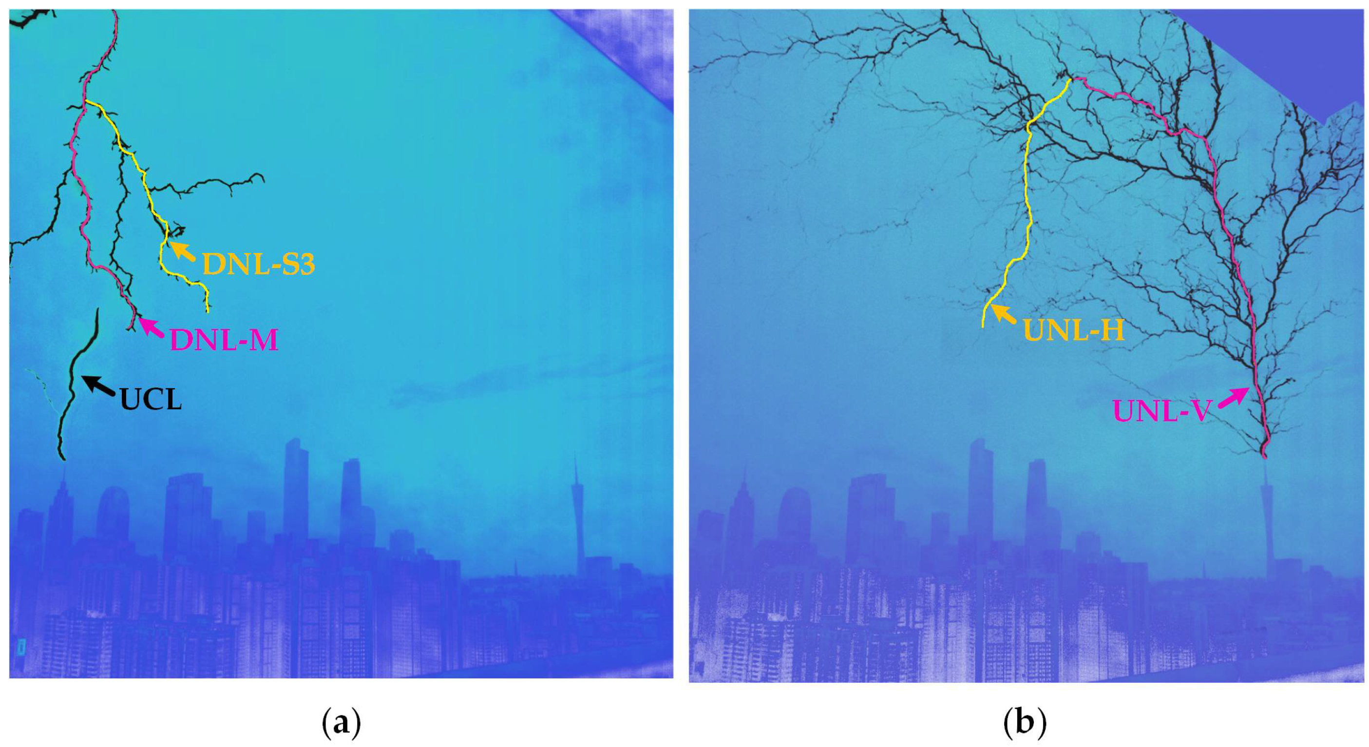
Figure 2 shows the complete paths of the DNL and the UNL in the FOV by superimposing all the sequence images with the pseudo-color processing method. Although propagation directions were different, both negative leaders displayed similar multi-branches features during the entire propagation. In Figure 2a, two categories of leader channels are concerned for the DNL, i.e., the main channel (DNL-M) and the remaining secondary channels (DNL-S) [34]. The DNL-M was the one with the longest duration and finally connected with the upward connecting leader. The DNL-S contains several channels that neither propagated towards the upward connecting leader nor were connected to the upward connecting leader. The DNL-S3 was chosen for statistical analysis because of a sufficient number of branches and a similar propagation trend to the DNL-M.
Figure 2b shows the coral-like branch structure of the UNL during the whole process in a positive flash. The UNL is divided into the vertical stage (UNL-V) and the horizontal stage (UNL-H), depending on the propagation direction. The former indicates a vertical upward propagation of the UNL after starting from a grounded building. The latter was at a high altitude of nearly 3 km, and the UNL turned into a horizontal development stage. It is worth noting that the “downward trend” in the two-dimensional optical image is the optical illusion created in the sensor while the UNL-H extends into the distance horizontally.
Overall, there are two propagation directions for the UNL (horizontal and vertical). The different orientation of DNL channels is affected by the attraction of the upward connecting leader with opposite polarity. Negative leaders selected in Figure 2 can be classified into four categories based on the different propagation directions, i.e., UNL-V, UNL-H, DNL-M, and DNL-S.
Table 3 demonstrates the number of branches and the average velocities during the entire propagation for four categories of negative leaders. The number of branches is the sum of branch channels on both sides of negative leaders distinguished on the superimposed images. The average velocity is indicated by the average velocity of the leader tip over the entire recorded development. Each category of negative leaders is abundant in branches, with numbers exceeding 30. Specifically, it is the first report of a UNL with more than 5 km in length and over 100 branches. The average velocities for four negative leaders range from 3.82 × 10⁵ to 5.78 × 10⁵ m/s, close to reports in Hill et al. [4], Jiang et al. [16], Pu et al. [31], and Wu et al. [33].

3.2. Branching Morphology of Negative Leaders

Taking the branch of UNL-V as an example, the branching morphology of negative leaders is characterized by the deflection angle and the included angle. Before introducing the method to measure the angles, the leader branches are distinguished into the strong branch (SB) and the weak branch (WB) at each branching. The former refers to the branch that eventually forms a section of the UNL’s main channel with the longest duration, while the latter refers to the branch that does not become a section of the main channel and gradually decays. The deflection angles of SB and WB are defined as the angle between the corresponding branch orientation and the previous direction of leader development, i.e., α and β, as shown in Figure 3. In addition, the included angles (θ) between SB and WB are also measured. When SB and WB appear on different sides of the previous direction of leader development, the calculation method of the included angle is θ = α + β, as shown in Figure 3a; if not, the calculation method is θ = α − β in Figure 3b.
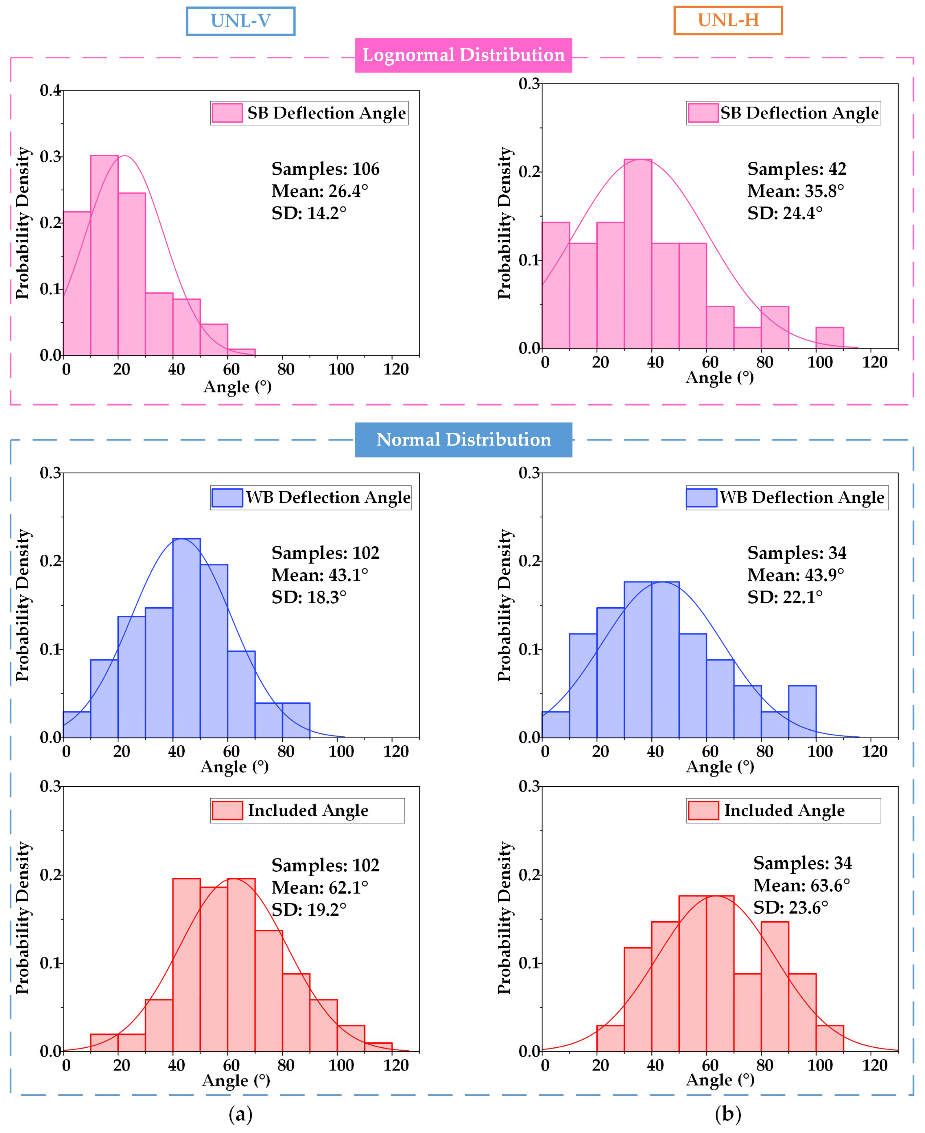
Figure 4 exhibits the frequency distribution histogram of angle parameters for the UNL branches with the solid lines representing the probability distribution curve. It can be seen from Figure 4a that the distribution of SB deflection angle for the UNL-V approximately conforms to the lognormal distribution. The WB deflection angle and included angle for the UNL-V are in line with the normal distribution. The mean values of α, β, and θ are 26.4°, 43.1°, and 62.1°, with standard deviations of 14.2°, 18.3°, and 19.2°, respectively. Statistical results show that over 70% of α range from 0–30°, indicating that SBs tend to propagate along the previous direction of leader development. The frequency distribution histograms of angle parameters for the UNL-H are illustrated in Figure 4b. The mean values of α, β, and θ are 35.8°, 43.9°, and 63.6°, with standard deviations of 24.4°, 22.1°, and 23.6°, respectively. In terms of distribution functions and the statistical values of β and θ, the results representing the branching morphology of the UNL-H have similarities to the UNL-V. However, the mean value of α and the standard deviation of angles for the UNL-H are larger than the UNL-V. It can be found that SBs of the UNL-H are more likely to deviate from the previous direction of leader development.
For the DNL, the frequency distribution histogram of angle parameters is shown in Figure 5. The distribution of α for the DNL approximately meets the lognormal distribution, and the β and θ conform to the normal distribution. The mean values of α, β, and θ for the DNL-M are 22.2°, 39.5°, and 63.6°, respectively, with standard deviations below 20°. For the DNL-S3, mean values of α, β, and θ are 32.3°, 44.4°, and 66.1°, respectively, with standard deviations over 20°, apart from β with 18.9°. Compared with the DNL-S3, all angles for the DNL-M show lower mean values and standard deviations, except for the similar standard deviation of β. Both SBs and WBs of the DNL-M tend to propagate along the previous propagation direction, and less dispersion of angle parameters reflects the consistency of the development pathway. Although the propagation directions are different for negative leaders, the morphological resemblances of leader branches have been found in UNL-H, UNL-V, and DNL-S, besides the lower α of 22.4° for the UNL-H. While mean values of all angles for the DNL-M are lower than the other three categories of negative leaders, especially for α and θ, the dispersion of angles characterized by the standard deviation is smaller. These statistical results suggest that the consistency of branching morphology is remarkable for the DNL-M.

3.3. Effect of Branching on Leader Velocity

When branching behaviors occur within a fixed frame interval, the number of bifurcation points on the optical image can describe the frequency of branching behavior. Thus, the effect of branching on leader velocity can be characterized by the relationship between the number of branch points and the average velocity in the corresponding time interval. As the elongation within the interval determines the velocity of negative leaders, it is essential to analyze the elongation of the leader tip on optical images during the emergence of branching. Figure 6a shows seven consecutive high-speed camera frames for the UNL-V in a fixed frame interval of 74.07 μs, with a maximum number of three branching points (frame 3) or no branching (frame 5). When branching behaviors occur twice or more in the interval, vertical elongations of the leader tip were reduced by 11.12 m, 2.78 m, and 25.02 m (marked by a yellow downward arrow), as shown in frames 3, 4, and 6, respectively.
To further investigate the effect of branching on the velocity of the UNL over the entire development process, the corresponding relationship between leader velocity and the number of bifurcation points is analyzed, as shown in Figure 6b,c. Note that leader velocity represents the average velocity of the leader tip during the stepping in a fixed time interval, and the stepping is not analyzed individually. Leader velocities are in the range of 2.2–11.3 × 10⁵ m/s and 1.0–11.9 × 10⁵ m/s for the UNL-H and the UNL-V, respectively. Both the vertical and horizontal velocities of the UNL exhibit a downtrend when branching occurs twice and more. Number 0 of the bifurcation point is not marked, indicating that no branches emerge. In addition, when the average velocity of leader propagation exceeded 7.0 × 10⁵ m/s from 2.2 ms to 3.2 ms (the yellow rectangular area of Figure 6b), the frequency of the branching behavior has no correlation effect on leader velocity for UNL-V with large fluctuations of the leader velocity.
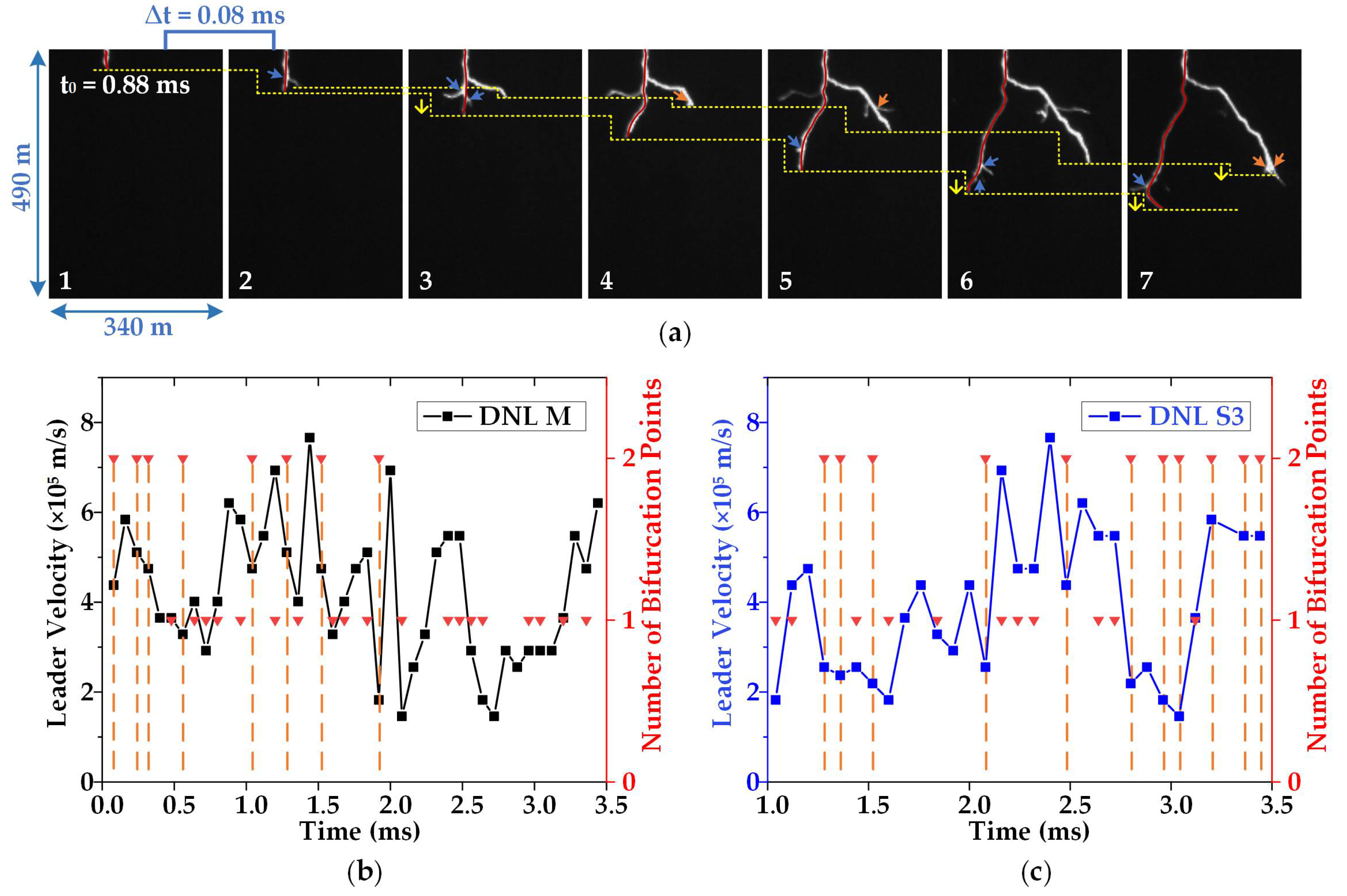
Figure 7 illustrates the effect of branching on leader velocity for the DNL, with the same method used in Figure 6. When the number of bifurcation points increases to two within a frame interval of 80 μs (frames 3, 6, and 7), the vertical elongations of DNL-M and DNL-S3 are reduced by a range of 8.76–17.52 m in Figure 7a. The branching behaviors of the different channels for the DNL were shown to be independent. Figure 7b,c shows that the velocities of two negative leaders range from 1.4 × 10⁵ m/s to 7.7 × 10⁵ m/s with large fluctuations. Similar to the effect of branching on the velocity of the UNL, velocities of DNL-M and DNL-S3 slow down when branching behavior occurs twice within the interval. In addition, there is a discrepancy in the frequency of branching behavior at different times for DNL-M and DNL-S3 in Figure 7b,c. During the first 2 ms, their branching behavior followed a similar pattern of variation, with different numbers of bifurcation points alternating in the interval. However, in the last 2.5 ms to 3.5 ms, the probability of branching for the DNL-M clearly declines, showing that the number of bifurcation points is one or zero in the interval. At this time, the majority number of bifurcation points is two for the DNL-S3, with multiple branches.
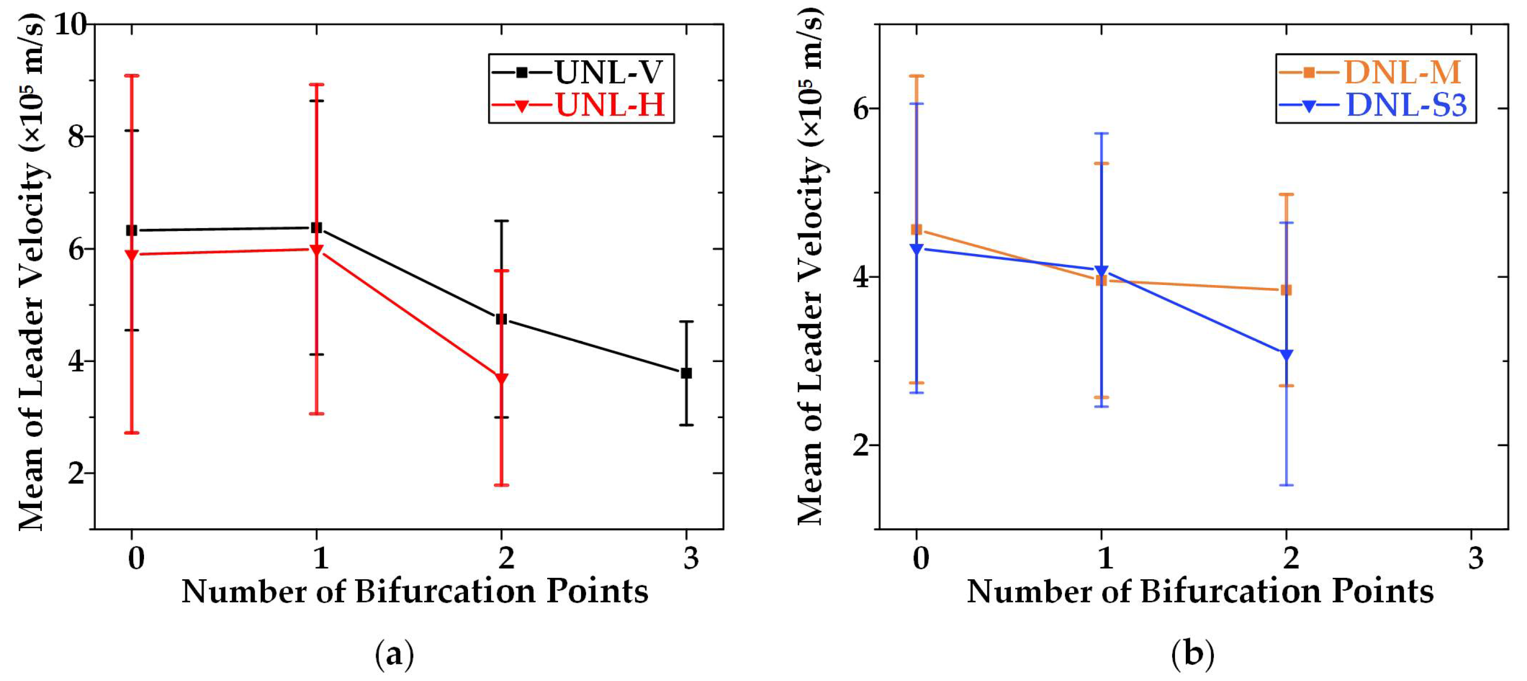
Figure 8 shows the mean value of leader velocity with the same number of bifurcation points, and the error bars are marked. The variation pattern of the mean value of leader velocity varying with bifurcation number is similar for UNL-V and UNL-H, as shown in Figure 8a. When the number of bifurcation points increases from one to two, the mean values of leader velocity for UNL-V and UNL-H decrease from 6.4 × 10⁵ m/s to 4.7 × 10⁵ m/s and 6.0 × 10⁵ m/s to 3.7 × 10⁵ m/s, respectively. In particular, for the UNL-V, when the number of bifurcation points reaches three, the mean value of leader velocity is even reduced to 3.8 × 10⁵ m/s. In Figure 8b, the mean values of velocity for DNL-M and DNL-S3 decrease as the number of bifurcation points increases. However, the variation pattern of the mean value of leader velocity with the bifurcation number for the DNL is different from the UNL. When one bifurcation occurs, the mean values of velocities of DNL-M and DNL-S3 were reduced by 0.4 × 10⁵ m/s and 0.2 × 10⁵ m/s, respectively. Furthermore, the velocity of the DNL-S3 is more sensitive to branching behavior than DNL-M, resembling UNL-V and UNL-H. In general, the velocity for four categories of negative leaders with different propagation directions could be affected by branching behaviors. When bifurcation occurs twice or more, there is a noticeable downtrend in leader velocity.

4. Discussion

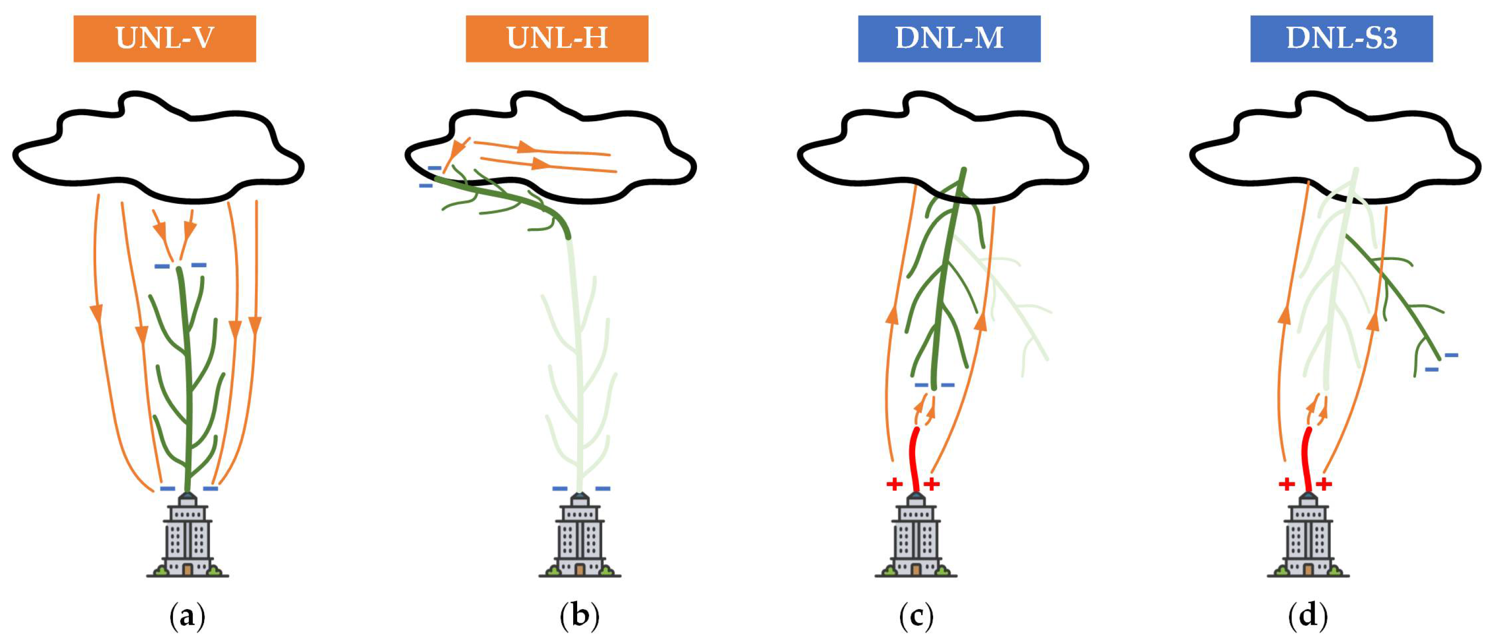
The propagation direction of negative leaders is determined by electric fields [35,36,37,38,39]. Comparing branching features of negative leaders with different propagation directions explores the effect of electric fields on branching patterns. To understand how the electric field affects the propagation direction and the branches of negative leaders, Figure 9 illustrates the distinction between electric fields for four categories of negative leaders, i.e., UNL-V, UNL-H, DNL-M, and DNL-S.
The UNL starts from a ground building and propagates upward. A thundercloud-to-ground electric field is formed between a positive charge in the thundercloud and a ground-induced negative charge in Figure 9a. The electric field ahead of UNL-V comprises thundercloud-to-ground and thundercloud-to-leader electric fields in the same vertically upward direction. When the UNL is at a higher attitude close to the thundercloud, a horizontal thundercloud electric field, which dominates leader development, is formed by the positive and negative charge regions inside the thundercloud [18,40]. Thus, the propagation direction of the UNL turns into the horizontal segment, as shown in Figure 9b. The total electric field consists of the approximately horizontal thundercloud field and the vertical thundercloud-to-leader field. Since the branch location is closely related to electric fields ahead of the leader tip, the probability of branching is higher where the electric field is stronger [41,42,43,44,45,46,47]. As a result, SBs are more likely to propagate along the previous direction of leader development with a stronger electric field than WBs. When UNL-H is close to the thundercloud, the increase in randomness and instability of the electric field could be attributed to the complex structure of thundercloud charges [35,48,49]. Hence, there is much uncertainty about the location of branching formation owing to fluctuations in the electric field ahead of the leader tip, resulting in the larger SB deflection angle and the dispersion of angles for UNL-H.
Figure 9c,d shows different attraction effects of the upward connecting leader by enhancing the electric field for the DNL. The thundercloud-to-ground electric field forms the background electric field for both leader channels. However, the local electric field in front of DNL-M is enhanced by the attraction of the upward connecting leader, with little effect on DNL-S. The enhancement is noticeable when two leaders with opposite polarities get closer. With the highest electric field in the common region between opposite polarity leaders, the branches of DNL-M tend to develop in this direction because of the high probability of branching. Thus, the probability and randomness of branching of the DNL-M decrease as close to the upward connecting leader.
Moreover, when a leader splits into two branch channels, the potential of the previous leader is conducted to two new tips through branch channels. In the case of multiple branching of the leader tip, the downtrend of leader velocity may be due to the low conductivity of the multiple new channels, resulting in lower potential transmission to the tips. Although the velocity of DNL-M decreases with multiple branching, the enhancement of the electric field makes the leader tip newly formed less affected by branching behaviors, and the branching of DNL-M have minimal impact on its velocity.
It is necessary to emphasize that the optical image describes the projection of a three-dimensional target onto a two-dimensional plane. The projected angle on the field of view, which directly determines the angle and velocity statistics in two dimensions, plays an important role in discussing the result. Although the absolute values of angles indicating branching morphology are based on the current field of view, the distribution pattern of branch angles with the same type should be common.

5. Conclusions

Branching features of four categories of negative leaders with different propagation directions, i.e., UNL-V, UNL-H, DNL-M, and DNL-S, were analyzed and compared. The branching morphology, characterized by deflection and included angles, was analyzed in detail based on statistical results. The variation pattern of leader velocity with the branching was additionally investigated. This is the first report of a UNL with a length of more than 5 km and over 100 branches. The main results are summarized as follows:
  • The distribution of SB deflection angle approximately conforms to the lognormal distribution. WB deflection and included angles are in line with normal distribution. SBs tend to propagate along the previous direction of leader development with a lower deflection angle than WBs by over 10°.
  • Similarities of branching morphology have been found in UNL-H, UNL-V, and DNL-S, with the mean values of near 30°, 45°, and 60°, for SB deflection angle, WB deflection angle, and included angle, respectively. In contrast, the branches of DNL-M tend to have less dispersion of angle distributions and propagations along the previous leader’s direction.
  • The velocity of the four categories of negative leaders with different propagation directions could be affected by branching behaviors. When two or more branching behaviors occur, there is a downtrend in the leader velocity, and the branching behaviors of DNL-M have minimal impact on its velocity.
In further research, laboratory discharges in a long air gap could be investigated to simulate lightning leaders. The experimental conditions could be controlled effectively, and multiple characteristic parameters of lightning leaders (electrical, thermodynamic, and optical)) are available to be measured simultaneously.

Author Contributions

Conceptualization, Y.L. and X.W.; methodology, Y.L.; validation, Y.L., X.W., X.L., L.L., G.L., M.L., L.Q., B.L., H.C., J.H. and L.C.; formal analysis, Y.L., X.W. and X.L.; investigation, Y.L., X.W., L.L., G.L. and H.C.; resources, L.L., G.L., M.L., L.Q., B.L. and H.C.; data curation, Y.L., L.L., G.L., M.L., L.Q., B.L. and H.C.; writing—original draft preparation, Y.L.; writing—review and editing, Y.L., X.W and X.L.; visualization, Y.L. and X.W.; supervision, J.H. and L.C.; project administration, J.H. and L.C.; funding acquisition, J.H. and L.C. All authors have read and agreed to the published version of the manuscript.

Funding

This research was funded by the National Engineering Research Center of UHV Technology and New Electrical Equipment of China, grant number NELUHV-2021-KF-02.

Institutional Review Board Statement

Not applicable.

Informed Consent Statement

Not applicable.

Data Availability Statement

Not applicable.

Conflicts of Interest

The authors declare no conflict of interest.

References

  1. Berger, K. Novel observations on lightning discharges: Results of research on Mount San Salvatore. J. Frankl. Inst. 1967, 283, 478–525. [Google Scholar] [CrossRef]
  2. Orville, R.E.; Idone, V.P. Lightning leader characteristics in the thunderstorm research international program (TRIP). J. Geophys. Res. Ocean. 1982, 87, 11177–11192. [Google Scholar] [CrossRef]
  3. Rakov, V.A.; Uman, M.A. Lightning: Physics and Effects; Cambridge University Press: Cambridge, UK, 2003. [Google Scholar]
  4. Hare, B.M.; Scholten, O.; Dwyer, J.; Ebert, U.; Nijdam, S.; Bonardi, A.; Buitink, S.; Corstanje, A.; Falcke, H.; Huege, T.; et al. Radio emission reveals inner meter-scale structure of negative lightning leader steps. Phys. Rev. Lett. 2020, 124, 105101. [Google Scholar] [CrossRef]
  5. Shindo, T. Lightning striking characteristics to tall structures. IEEJ Trans. Electr. Electron. Eng. 2018, 13, 938–947. [Google Scholar] [CrossRef] [Green Version]
  6. Wang, J.; Su, R.; Wang, J.; Wang, F.; Cai, L.; Zhao, Y.; Huang, Y. Observation of five types of leaders contained in a negative triggered lightning. Sci. Rep. 2022, 12, 6299. [Google Scholar] [CrossRef]
  7. Hill, J.; Uman, M.; Jordan, D. High-speed video observations of a lightning stepped leader. J. Geophys. Res. Atmos. 2011, 116. [Google Scholar] [CrossRef] [Green Version]
  8. Petersen, D.A.; Beasley, W.H. High-speed video observations of a natural negative stepped leader and subsequent dart-stepped leader. J. Geophys. Res. Atmos. 2013, 118, 12,110–112,119. [Google Scholar] [CrossRef]
  9. Biagi, C.; Uman, M.; Hill, J.; Jordan, D. Negative leader step mechanisms observed in altitude triggered lightning. J. Geophys. Res. Atmos. 2014, 119, 8160–8168. [Google Scholar] [CrossRef]
  10. Qi, Q.; Lu, W.; Ma, Y.; Chen, L.; Zhang, Y.; Rakov, V.A. High-speed video observations of the fine structure of a natural negative stepped leader at close distance. Atmos. Res. 2016, 178, 260–267. [Google Scholar] [CrossRef]
  11. Khounate, H.; Nag, A.; Plaisir, M.N.; Imam, A.Y.; Biagi, C.J.; Rassoul, H.K. Insights on Space-Leader Characteristics and Evolution in Natural Negative Cloud-to-Ground Lightning. Geophys. Res. Lett. 2021, 48, e2021GL093614. [Google Scholar] [CrossRef]
  12. Krider, E.P.; Weidman, C.D.; Noggle, R.C. The electric fields produced by lightning stepped leaders. J. Geophys. Res. 1977, 82, 951–960. [Google Scholar] [CrossRef]
  13. Chen, M.; Takagi, N.; Watanabe, T.; Wang, D.; Kawasaki, Z.I.; Liu, X. Spatial and temporal properties of optical radiation produced by stepped leaders. J. Geophys. Res. Atmos. 1999, 104, 27573–27584. [Google Scholar] [CrossRef]
  14. Lu, W.; Wang, D.; Takagi, N.; Rakov, V.; Uman, M.; Miki, M. Characteristics of the optical pulses associated with a downward branched stepped leader. J. Geophys. Res. Atmos. 2008, 113. [Google Scholar] [CrossRef] [Green Version]
  15. Bazelyan, E.M.; Raizer, Y.P. Lightning Physics and Lightning Protection; CRC Press: Boca Raton, FL, USA, 2000. [Google Scholar]
  16. Jiang, R.; Qie, X.; Zhang, H.; Liu, M.; Sun, Z.; Lu, G.; Wang, Z.; Wang, Y. Channel branching and zigzagging in negative cloud-to-ground lightning. Sci. Rep. 2017, 7, 3457. [Google Scholar] [CrossRef] [Green Version]
  17. Yuan, S.; Jiang, R.; Qie, X.; Sun, Z.; Wang, D.; Srivastava, A. Development of side bidirectional leader and its effect on channel branching of the progressing positive leader of lightning. Geophys. Res. Lett. 2019, 46, 1746–1753. [Google Scholar] [CrossRef]
  18. Syssoev, A.; Iudin, D.; Bulatov, A.; Rakov, V. Numerical simulation of stepping and branching processes in negative lightning leaders. J. Geophys. Res. Atmos. 2020, 125, e2019JD031360. [Google Scholar] [CrossRef]
  19. Qie, X.; Zhang, Y. A review of atmospheric electricity research in China from 2011 to 2018. Adv. Atmos. Sci. 2019, 36, 994–1014. [Google Scholar] [CrossRef]
  20. Beasley, W.; Uman, M.A.; Rustan, P., Jr. Electric fields preceding cloud-to-ground lightning flashes. J. Geophys. Res. Ocean. 1982, 87, 4883–4902. [Google Scholar] [CrossRef]
  21. Wang, C.; Sun, Z.; Jiang, R.; Tian, Y.; Qie, X. Characteristics of downward leaders in a cloud-to-ground lightning strike on a lightning rod. Atmos. Res. 2018, 203, 246–253. [Google Scholar] [CrossRef]
  22. Cooray, V.; Arevalo, L. Modeling the stepping process of negative lightning stepped leaders. Atmosphere 2017, 8, 245. [Google Scholar] [CrossRef] [Green Version]
  23. Schonland, B. The lightning discharge. Handb. Phys. 1956, 22, 576–628. [Google Scholar]
  24. Tran, M.; Rakov, V.; Mallick, S. A negative cloud-to-ground flash showing a number of new and rarely observed features. Geophys. Res. Lett. 2014, 41, 6523–6529. [Google Scholar] [CrossRef]
  25. Ding, Z.; Rakov, V.A.; Zhu, Y.; Tran, M.D. On a Possible Mechanism of Reactivation of Decayed Branches of Negative Stepped Leaders. J. Geophys. Res. Atmos. 2020, 125, e2020JD033305. [Google Scholar] [CrossRef]
  26. Ding, Z.; Rakov, V.; Zhu, Y.; Tran, M.; Kostinskiy, A.; Kereszy, I. Evidence and inferred mechanism of collisions of downward stepped-leader branches in negative lightning. Geophys. Res. Lett. 2021, 48, e2021GL093295. [Google Scholar] [CrossRef]
  27. Zhou, H.; Diendorfer, G.; Thottappillil, R.; Pichler, H.; Mair, M. Measured current and close electric field changes associated with the initiation of upward lightning from a tall tower. J. Geophys. Res. Atmos. 2012, 117. [Google Scholar] [CrossRef]
  28. Saba, M.M.; Schumann, C.; Warner, T.A.; Helsdon, J.H.; Orville, R.E. High-speed video and electric field observation of a negative upward leader connecting a downward positive leader in a positive cloud-to-ground flash. Electr. Power Syst. Res. 2015, 118, 89–92. [Google Scholar] [CrossRef]
  29. Visacro, S.; Guimaraes, M.; Murta Vale, M.H. Features of upward positive leaders initiated from towers in natural cloud-to-ground lightning based on simultaneous high-speed videos, measured currents, and electric fields. J. Geophys. Res. Atmos. 2017, 122, 12,786–712,800. [Google Scholar] [CrossRef]
  30. Nag, A.; Rakov, V.A. Positive lightning: An overview, new observations, and inferences. J. Geophys. Res. Atmos. 2012, 117. [Google Scholar] [CrossRef]
  31. Pu, Y.; Jiang, R.; Qie, X.; Liu, M.; Zhang, H.; Fan, Y.; Wu, X. Upward negative leaders in positive triggered lightning: Stepping and branching in the initial stage. Geophys. Res. Lett. 2017, 44, 7029–7035. [Google Scholar] [CrossRef]
  32. Huang, H.; Wang, D.; Wu, T.; Takagi, N. Formation Features of Steps and Branches of an Upward Negative Leader. J. Geophys. Res. Atmos. 2018, 123, 12,597–12,605. [Google Scholar] [CrossRef]
  33. Wu, T.; Wang, D.; Takagi, N. Upward negative leaders in positive upward lightning in winter: Propagation velocities, electric field change waveforms, and triggering mechanism. J. Geophys. Res. Atmos. 2020, 125, e2020JD032851. [Google Scholar] [CrossRef]
  34. Wang, X.; Zhao, X.; Hao, Y.; Cai, H.; Liu, G.; Liao, M.; Qu, L. High-speed video observations of branching behaviors in downward stepped leaders and upward connecting leaders in negative natural lightning. J. Atmos. Sol.-Terr. Phys. 2019, 183, 61–66. [Google Scholar] [CrossRef]
  35. Mansell, E.R.; MacGorman, D.R.; Ziegler, C.L.; Straka, J.M. Simulated three-dimensional branched lightning in a numerical thunderstorm model. J. Geophys. Res. Atmos. 2002, 107, ACL 2-1–ACL 2-12. [Google Scholar] [CrossRef]
  36. Qie, X.; Yuan, S.; Zhang, H.; Jiang, R.; Wu, Z.; Liu, M.; Sun, Z.; Pu, Y.; Li, J.; Srivastava, A.; et al. Propagation of positive, negative, and recoil leaders in upward lightning flashes. Earth Planet. Phys. 2019, 3, 102–110. [Google Scholar] [CrossRef]
  37. Scholten, O.; Hare, B.; Dwyer, J.; Liu, N.; Sterpka, C.; Kolmašová, I.; Santolík, O.; Lán, R.; Uhlíř, L.; Buitink, S. A distinct negative leader propagation mode. Sci. Rep. 2021, 11, 16256. [Google Scholar] [CrossRef] [PubMed]
  38. Xie, S.; D’Alessandro, F.; Zhao, X. A three-dimensional downward leader model incorporating geometric and physical characteristics. Electr. Power Syst. Res. 2018, 163, 10–17. [Google Scholar] [CrossRef]
  39. Adekitan, A.I.; Rock, M. The impact of space point definition on dynamic electro-geometrical model of lightning strike probability. Electr. Power Syst. Res. 2020, 184, 106336. [Google Scholar] [CrossRef]
  40. Williams, E.R. The tripole structure of thunderstorms. J. Geophys. Res. Atmos. 1989, 94, 13151–13167. [Google Scholar] [CrossRef]
  41. Kawasaki, Z.; Matsuura, K. Does a lightning channel show a fractal? Appl. Energy 2000, 67, 147–158. [Google Scholar] [CrossRef]
  42. Rahiminejad, A.; Vahidi, B.; He, J. A fractal-based stepped downward leader model including branched channel charge distribution and branch fading. Electr. Power Syst. Res. 2019, 176, 105940. [Google Scholar] [CrossRef]
  43. Shi, W.; Li, Q.; Zhang, L. A stepped leader model for lightning including charge distribution in branched channels. J. Appl. Phys. 2014, 116, 103303. [Google Scholar] [CrossRef]
  44. Nguyen, D.; Deegan, G.; D’Alessandro, F. Fractal nature of probabilistic model of lightning discharge. In Proceedings of the IEEE Region 10 International Conference on Electrical and Electronic Technology, Singapore, 19–22 August 2001; pp. 814–818. [Google Scholar]
  45. Li, J.; Yang, Q.; Sima, W.; Sun, C.; Yuan, T.; Zahn, M. A new estimation model of the lightning shielding performance of transmission lines using a fractal approach. IEEE Trans. Dielectr. Electr. Insul. 2011, 18, 1712–1723. [Google Scholar] [CrossRef]
  46. Guo, J.; Zhang, X.; Wang, B.; Hao, X.; Zheng, S.; Xie, Y.Z. A three-dimensional direct lightning strike model for lightning protection of the substation. IET Gener. Transm. Distrib. 2021, 15, 2760–2772. [Google Scholar] [CrossRef]
  47. Ioannidis, A.I.; Tsovilis, T.E. Shielding Failure of High-Voltage Substations: A Fractal-Based Approach for Negative and Positive Lightning. IEEE Trans. Ind. Appl. 2021, 57, 2317–2325. [Google Scholar] [CrossRef]
  48. Grigor’Ev, A.; Shiryaeva, S. The possible physical mechanism of initiation and growth of lightning. Phys. Scr. 1996, 54, 660. [Google Scholar] [CrossRef]
  49. Beroual, A.; Rakotonandrasana, J.; Fofana, I. Predictive dynamic model of the negative lightning discharge based on similarity with long laboratory sparks. Part 1: Physical process and modeling. IEEE Trans. Dielectr. Electr. Insul. 2010, 17, 1551–1561. [Google Scholar] [CrossRef] [Green Version]
Figure 1. The height and the distance from the observation site of the seven buildings.
Atmosphere 13 01217 g001
Figure 2. The complete paths of two cases by superimposing the sequence images with the pseudo-color processing method: (a) DNL-20180702; (b) UNL-20190427. Four negative leaders and an upward connecting leader (UCL) marked by different colors.
Atmosphere 13 01217 g002
Figure 3. Optical images marked by SB, WB, and deflection angle (α and β) for the UNL: (a) the included angle is θ= α + β when SB and WB appear on different sides of the previous direction of leader development; (b) the included angle is θ = α − β when SB and WB are on the same side of the previous direction of leader development.
Atmosphere 13 01217 g003
Figure 4. Frequency distribution histogram of angle parameters for leader branches: SB deflection angle α, WB deflection angle β, and included angle θ for (a) UNL-V and (b) UNL-H. The solid lines represent the probability distribution curve, and SD is the standard deviation.
Atmosphere 13 01217 g004
Figure 5. Frequency distribution histogram of angle parameters for leader branches: SB deflection angle α, WB deflection angle β, and included angle θ for (a) DNL-M and (b) DNL-S3. The solid lines represent the probability distribution curve, and SD is the standard deviation.
Atmosphere 13 01217 g005
Figure 6. (a) Seven consecutive high-speed camera frames for the UNL-V, solid red line indicate the pathway of main channel; blue arrow indicates the bifurcation points; and the horizontal and vertical yellow dashed lines represent spatial location and vertical elongation of leader tip, respectively: the corresponding relationship between leader velocity and the number of bifurcation points over the whole propagation for (b) UNL-V and (c) UNL-H, where perpendicular dashed segment in orange expresses two bifurcation points.
Atmosphere 13 01217 g006
Figure 7. (a) Seven consecutive high-speed camera frames for the DNL, the solid red line indicates the pathway of the DNL-M; arrows indicate the bifurcation points; the horizontal and vertical yellow dashed lines represent spatial location and vertical elongation of leader tip, respectively; and the corresponding relationship between leader velocity and the number of bifurcation points over the whole propagation for DNL-M (b) and for DNL-S3 (c), where perpendicular dashed segment in orange expresses two bifurcation points.
Atmosphere 13 01217 g007
Figure 8. The mean value of leader velocity with the same number of bifurcation points, and the error bars are marked: (a) the DNL of vertical segment (UNL-V) and horizontal segment (UNL-H); (b) the UNL of main channel (DNL-M) and secondary channel (DNL-S3).
Atmosphere 13 01217 g008
Figure 9. The distinction between electric fields by schematic diagrams for four categories of negative leaders, green lines as negative leaders; red lines as positive leaders; orange lines with arrows as the direction of electric fields: (a) UNL-V; (b) UNL-H; (c) DNL-M; (d) DNL-S.
Atmosphere 13 01217 g009
Table 1. Types and fundamental characteristics of negative leaders.
Type of Negative LeadersOrigination LocationPolarity of LightningDirection of PropagationProbability of Occurrence
DNLInside the ThundercloudNegativeDownward70–90%
UNLGrounded BuildingsPositiveUpward10%
Table 2. Basic information of the optical observation for two cases.
Case IDLocal TimeTemporal ResolutionSpatial ResolutionRecording DurationFOV
DNL-2018070213:22:42 on
2 July 2018
80 μs2.92 m3.5 ms2990 m × 2990 m
UNL-2019042716:20:18 on
27 April 2019
74.07 μs2.78 m15 ms2780 m × 2847 m
Table 3. The number of branches and the average velocity during the entire propagation for four categories of leaders.
Case IDLeader TypeNumber of BranchesAverage Velocity (×105 m/s)
DNL-20180702DNL-M354.23
DNL-S3313.82
UNL-20190427UNL-V1025.63
UNL-H345.78
Publisher’s Note: MDPI stays neutral with regard to jurisdictional claims in published maps and institutional affiliations.