Article

A Quality Control Method and Implementation Process of Wind Profiler Radar Data

School of Geophysics, Chengdu University of Technology, Chengdu 610051, China
*
Author to whom correspondence should be addressed.
Atmosphere 2022, 13(5), 796; https://doi.org/10.3390/atmos13050796
Submission received: 13 April 2022 / Revised: 7 May 2022 / Accepted: 11 May 2022 / Published: 13 May 2022
(This article belongs to the Special Issue Identification and Optimization of Retrieval Model in Atmosphere)

Abstract

:
Wind profiler radar (WPR) is used for all-weather atmospheric wind-field monitoring. However, the reliability of these observations reduces significantly when there is electromagnetic interference echo, generally caused by ground objects, birds, or rain. Therefore, to optimize the data reliability of WPR, we proposed a synthetic data quality control process. The process included the application of a minimum connection method, judgment rule, and median test optimization algorithm for optimizing clutter suppression, spectral peak symmetry detection, and radial speed, respectively. We collected the base data from a radiosonde and multiple radars and conducted an experiment using these data and algorithms. The results indicated that the quality control method: (1) had good adaptability to multiple WPRs both in clear sky and precipitation; (2) was useful for suppressing ground clutter and (3) was superior to those of the manufacturer as a whole. Thus, the data quality control method proposed in this study can improve the accuracy and reliability of WPR products and multiple types of WPR, even when they function under vastly different weather conditions.

1. Introduction

Wind profiler radar (WPR) is a type of advanced weather observation device that can record atmospheric wind, humidity, temperature, and other physical quantities, using backscattering electromagnetic waves from atmospheric turbulence [1,2,3,4,5]. It has been widely used in atmospheric fields [6,7,8] and has high measurement accuracy [9]. The growing amount and more extensive application range of WPR data require a more objective and accurate understanding. Compared with conventional sounding equipment, WPR has more serious data quality problems, because of the complex interference signals and lower backscattered signal-to-noise ratio (SNR) associated with atmospheric turbulence [10,11,12,13]. To address this problem, several studies have been conducted on WPR data quality control methods.
In general, the inversion steps of wind profile include intermediate frequency signal processing, power spectrum processing, and Doppler speed parameter estimation [14,15,16]. Therefore, the existing literature on WPR data can be divided into two types. The first type focuses on processing basic radar power spectrum data. For example, Lehmann, V. [17,18] presented a signal processing method for the suppression of intermittent clutter echoes, which made use of a discrete Gabor frame expansion of the coherently averaged time-series data in combination with a statistical filtering approach to exploit the different signal characteristics between signal and clutter. Bianco, L. [19] proposed a Gabor transform-based algorithm to identify and eliminate intermittent signal contamination in UHF wind profiling radars. Chen, Y.W. [20] used a genetic algorithm to resolve the overlapping signals. Hashimoto, T. [21] proposed a novel method for the automatic determination of the diagonal-loading level for robust adaptive beam forming on radar wind profilers and balanced the degradation of the signal-to-interference ratio with that of the signal-to-noise ratio to maximize the detectability of the backscattered signals. Salonen, K. [22] confirmed that the main error sources for the radial wind observations are ground clutter and velocity ambiguity after a long-time observation quality monitoring, then used the HIRLAM quality control procedures to detect and reject most of these erroneous observations. May, P.T. [23] used modern peak detection algorithms to obtain high-quality wind estimates in the presence of clutter.
The second type focuses on quality control algorithms for wind data obtained after performing parameter estimation for the spectrum. For example, Barbré [24] introduced a signal-processing system, which uses a median filter to remove spurious Doppler spectral data and constrains the search for the atmospheric signal by a first guess and get good results. Kumar, S. [25] proposed that the averaging of winds is found to be more effective in removing outliers and reducing the RMSE. In the study proposed by Zhang, Y. [26], a quality control procedure was constructed to incorporate the profiler data from the wind-profiling network into the local data assimilation and forecasting systems. The results show that with quality control, the frequency distributions of the differences between the observations and the model background meet the requirements of a Gaussian distribution for data assimilation. Additionally, Nehrkorn, T. [27] described an application of optimum interpolation (OI) for quality control and a combination of wind profiler data with other observations of wind profiles.
The work performed in this study is summarized as follows:
Based on improvements to existing methods, a complete set of WPR quality control processes was presented. The flow of the algorithm avoided relatively tedious calculations, and thus, the process could be adapted for practical business applications;
Combined with actual cardinal data from WPRs, smoothing, filtering, minimum line object clutter suppression, spectrum peak search, and other methods were proposed to control the quality of the power spectrum data;
Consistency averaging, median testing, pattern splicing, and other methods were carried out to control the quality of radial wind data, which were generated after spectral parameter estimation;
Then, an experiment with different types of WPR and radiosonde data was carried out, and conclusions were drawn based on the comparison and verification of the actual data.
The remainder of this manuscript is organized as follows. Section 2 introduces the data sources used in the experiment and illustrates the quality control algorithm and processing method for the WPR data. Section 3 presents the comparative experiments, in which we compared our results with the manufacturer’s and radiosonde data. The findings demonstrated the effectiveness of the algorithm flow proposed in this study; notably, our method can be applied to different weather conditions and types of radar data. Section 4 and Section 5 provide a discussion of our results and the conclusions of our study, respectively.

2. Data and Methods

2.1. Data

The WPR data used in this study can be classified into two sources. The first set of power spectrum data was collected in April, May, and July 2019 by the CFL-06 WPR produced by the Beijing Institute of Radio Measurement. The radar was located in the southern suburbs of Beijing, China. The time resolution of the CFL-06 was 3 min, although its height resolution varied with different modes (120 m in the low mode and 240 m in the high mode). Moreover, the initial detection height was 150 m.
The second set of power spectrum data was collected during March, April, July, and August 2019 by the TWP8 WPR produced by the Beijing Metstar Radar Co., Ltd., located in Wuhua (Meizhou, China). Compared with CFL-06, TWP8 is a middle tropospheric WPR having a time resolution of 5 min, and its height resolution depends on the width of the pulse transmission. In our study, the height resolution was 120 m in the low mode and 240 m in the high mode. Considering that the data acquisition efficiency of the WPR within the boundary layer was relatively good and decreased rapidly above the layer, we only selected the power spectrum data below 6 km.

2.2. Methods

Generally, to estimate the power spectrum and moment parameters, the WPR power spectrum data must be decoded into the fast Fourier transform (FFT) data, according to the wind profiler data format. However, in practical applications, the decoded FFT data should be quality controlled to obtain highly precise and reliable parameters. The specific quality control processes proposed in this study are shown in Figure 1.

2.2.1. Smoothing Filter

The detection target of WPR is atmospheric turbulence, which generally has weak echo signals, especially when the SNR is relatively low and the atmospheric echo signals are scattered. In addition, because of the influence of impulsive noise, interference signals having narrow-spectrum widths and large amplitudes are often mistaken for atmospheric turbulence echoes. To reduce the impact of impulse noise and improve the SNR and spectrum peak recognition ability of WPRs, we used a smoothing filter to preprocess the power spectrum data.
The principle of N -point smoothing filtering applied in our study can be expressed as follows:
x ( m ) N e w = 1 N n = N 2 n = N 2 x ( m + n )
where x ( m ) N e w is the data array after processing, x ( m ) is the unprocessed data array and N is the width of the smoothing window. For example, if the window width N is 5, the smoothing point by step is 1, the fifth output point is x ( 5 ) N e w = 1 5 ( x ( 3 ) + x ( 4 ) + x ( 5 ) + x ( 6 ) + x ( 7 ) ) , the sixth output point is x ( 6 ) N e w = 1 5 ( x ( 4 ) + x ( 5 ) + x ( 6 ) + x ( 7 ) + x ( 8 ) ) and the m -th output point is x ( m ) N e w = 1 5 ( x ( m 1 ) + x ( m 1 ) + x ( m ) + x ( m + 1 ) + x ( m + 2 ) ) . After a N -point window was centered on each non-boundary data point in the dataset, all data points within the window were averaged to replace the original center point data. For boundary points, only three or four adjacent points were averaged to replace the original data.

2.2.2. Ground Clutter Suppression

Generally, WPR treats atmospheric turbulence as the detection target; however, weak turbulence echo signals are easily disturbed by ground clutter. In particular, below 2 km, weak atmospheric echo signals can be covered by ground clutter; this poses a challenge in the extraction of the power spectrum of the echo signal from the base data. In addition, strong ground clutter often causes errors in meteorological signal classification during the spectral peak search and affects the accuracy of wind-field inversion products. According to the principle of Doppler shift, the speed of ground clutter is near zero frequency and the Doppler speed of the target echo is almost zero, which makes it possible to eliminate ground clutter. In this study, we proposed a minimum connection method to remove ground clutter, consisting of the following steps.
  • First, the objective noise level method was used to determine the noise level, and the maximum values higher than the noise level were used as the possible signal peaks.
  • Then, a 13-point range centered on the 0 frequency of the power spectrum was used as the range of the signal spectrum peak judgment. If the peak point was outside this range, the turbulence signal within this range was considered undisturbed by ground clutter, whereas if the peak value was within this range, the turbulence signal was considered to be disturbed by ground clutter; thus, ground clutter removal was performed to address this issue.
  • Finally, the appropriate minimum values at both ends of the ground clutter signal were determined, and the results obtained by spherical interpolation were used to replace the data between the minimum values.
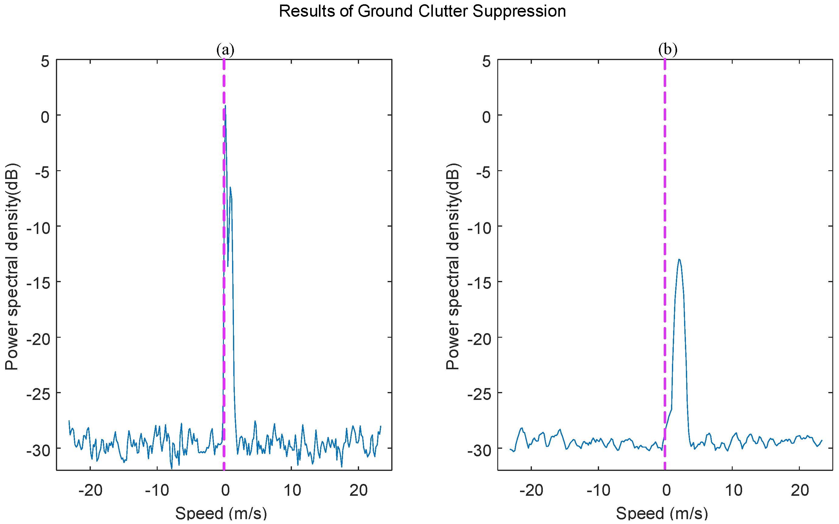
Figure 2 illustrates our findings before and after the suppression of ground clutter, where the dashed line represents zero speed. As shown in Figure 2a, ground clutter has a significant impact on the detection results of the WPR. After suppressing the ground clutter using the above method (Figure 2b), we could deduce that the method can effectively remove the ground clutter and obtain the true atmospheric turbulence echo.

2.2.3. Spectrum Peak Search

The echoes received by the WPR included weak turbulence and other interference scattering, such as those resulting from precipitation particles. During the precipitation period, the vertical speed of the precipitation particles caused the spectral peak of the power spectrum to shift significantly. Generally, if the interference is not suppressed, the radial wind speed calculated from the data will lead to a large error. In particular, interference (e.g., precipitation) is a major cause of errors in the calculation of horizontal wind speed. Therefore, it is important to accurately identify atmospheric turbulence echoes and suppress interferences.
The principle underlying the ability of WPR to detect atmospheric turbulence is based on the homogeneity of the atmosphere; that is, the atmospheric motion state of the relative beam detection range must be consistent, and the atmospheric turbulence echo signal of the relative beam should be symmetrical in the power spectrum. Because clutter signals, such as those from precipitation particles, generally do not have symmetrical characteristics, this feature can be used to differentiate these signals from atmospheric turbulence echoes. Although the actual atmosphere does not have ideal uniformity and the actual atmospheric turbulence echo signal is not completely symmetrical on the power spectral density, the difference is inconspicuous. The main steps of spectral peak search are explained below.
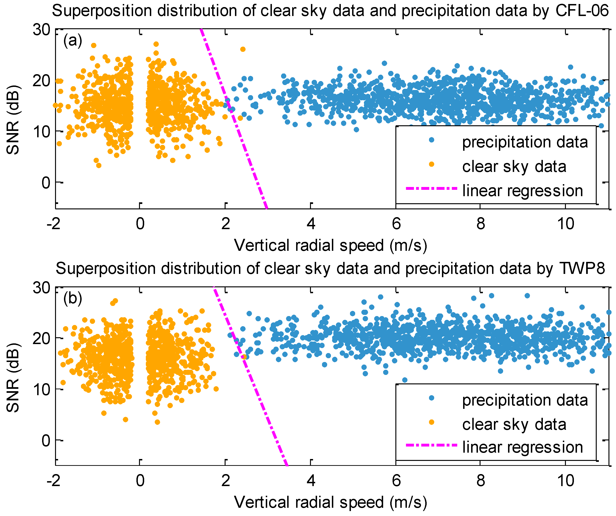
First, according to the method of calculating the precipitation judgment factor Y, proposed by references [28,29], the vertical radial velocity V is taken as X-axis and the SNR value as Y-axis. The data distribution of the two types of radars used in this study under two weather conditions is shown in Figure 3, and the discriminant function is obtained by the linear regression method.
Then, we determined whether the wind profile power spectrum was affected by precipitation by the linear regression result:
Y C F L - 06 = 61.3 + 22.1 · V + S N R
Y T W P 8 = 55 + 17.54 · V + S N R
where Y C F L 06 and Y T W P 8 are the judgment factors of the two types of WPR, V is the vertical radial velocity (m/s) and S N R is the signal-to-noise ratio (dB). If Y > 0, the data were affected by precipitation; otherwise, the data were unaffected.
For data that were not affected by precipitation, a power spectrum higher than the noise level was used for Gaussian fitting, and the maximum value was determined, according to the fitting result. If the S N R of the maximum value was greater than 5 dB, the point was marked as a spectral peak. For an opposite direction beam at the same height, the threshold for judging symmetry was set to 2.5 m/s, and for the same beam at a continuous height, the threshold for judging continuity was set to 3 m/s. The spectrum peaks were identified based on symmetry and continuity, and the atmospheric turbulence echoes were obtained after removing the other spectrum peaks.
For data affected by precipitation, the atmospheric turbulence echo can also be identified using the same strategy. Notably, compared to the precipitation spectrum peak position, the position of the atmospheric turbulence spectrum peak is always closer to the zero frequency. Therefore, if the identification results portrayed double peaks, the symmetry method was used to identify and complement the atmospheric turbulence echo. If the atmospheric turbulence echo was completely covered by the precipitation echo, the atmospheric turbulence spectrum peak of this range gate was omitted.
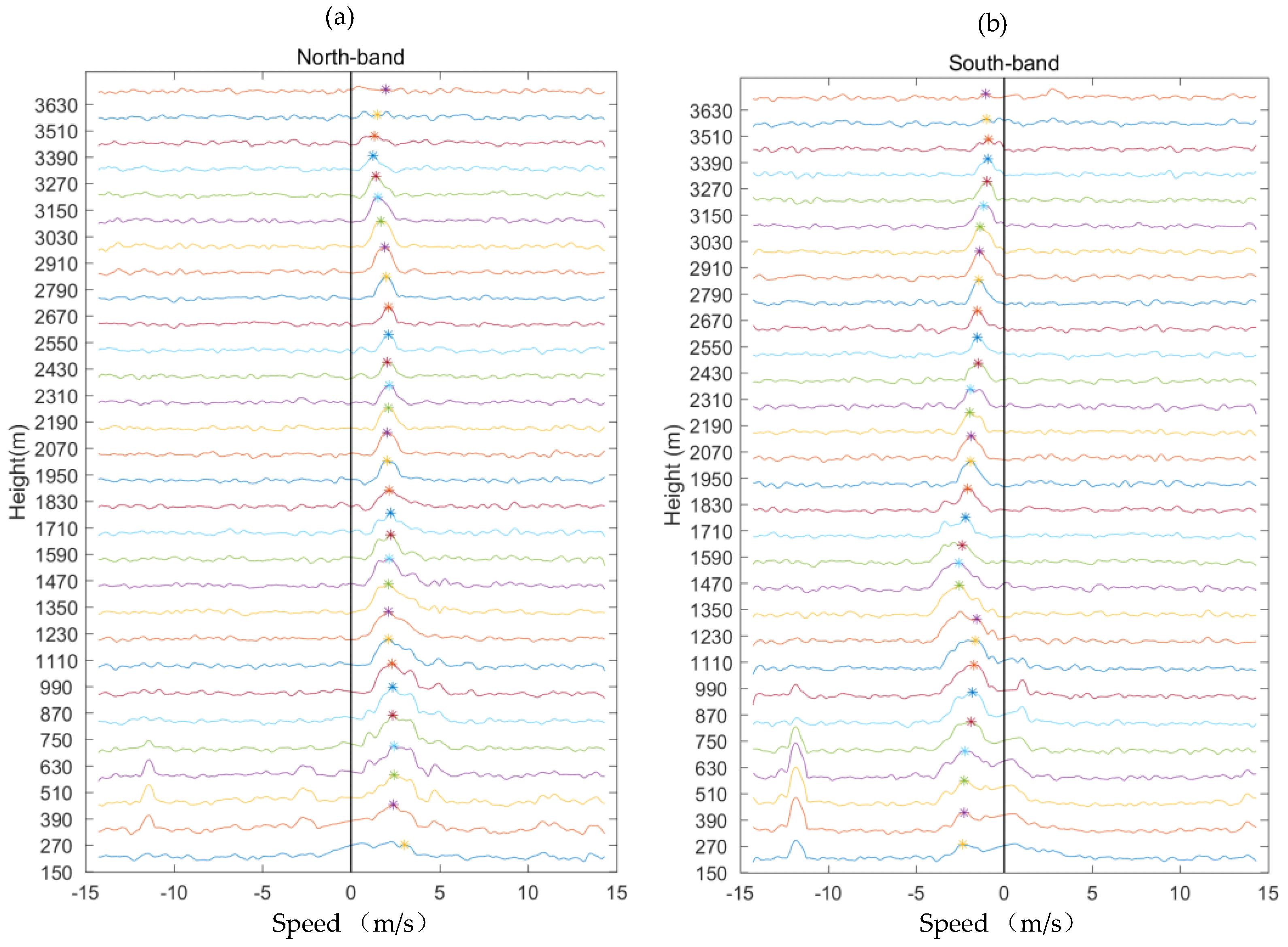
Figure 4 portrays the power spectrum of the opposite beam in low mode after multipeak processing. The results indicated that the spectrum peak in low mode had significant symmetry and continuity. The spectrum peak lines managed to avoid clutter, and a speed of more than 10 m/s was observed in the spectrum data below 750 m (height), after multipeak processing.

2.2.4. Parameter Calculation

Based on the previously mentioned spectral line-level quality control algorithm processing applied in our study, we estimated the values of spectral moment parameters of the power spectrum higher than the noise level. The echo power, average Doppler frequency, and velocity spectrum width were obtained using the following equations:
m 0 = i = 1 h p i
m 1 = i = 1 h v i p i
m 2 = i = 1 h v i 2 p i
where m 0 , m 1 , and m 2 represent the zero-order moment, first-order moment, and second-order central moment of the power spectrum, respectively; p i and v i represent the power and speed at the i -th point, respectively; and h represents the total number of range bins.
According to the above formulae, additional parameters were calculated using the following equations:
P r = m 0
v ˜ = m 1 m 0
w ˜ = 2 [ m 2 m 0 ( m 1 m 0 ) 2 ] 1 / 2
S N R = 10 log ( i = 1 h ( p i P N N ) P N )
where P r , v ˜ , w ˜ , and S N R represent the echo power, average radial velocity, velocity spectrum width, and signal-to-noise ratio, respectively; P N is the noise power; and N is the number of FFT points.

2.2.5. Consensus Average

The wind is one of the most rapidly changing meteorological elements, and rapid wind changes can compromise the representativeness and comparability of observational data. Therefore, to obtain more stable and representative data as the basis for reliable weather forecasting and climate statistics, the World Meteorological Organization stated that, during meteorological observations, the average value of meteorological elements in a certain period should be recorded.
The consensus average method is a classical method of processing the radial wind-speed data from WPR. It first checks the consistency of all data in the average period and collects similar data to form a set. Then, the set with the largest number of samples is averaged and used as the observation value for the time period. Notably, the consensus average is based on a consistency check that includes the following three parameters:
  • The consensus average time, which refers to the observation period;
  • The consensus deviation, which refers to the maximum error permitted when two observations occur at different times;
  • The consensus threshold, which refers to the minimum percentage of the total number of samples required when checking the consensus of the set having the largest number of samples.

2.2.6. Horizontal Wind Speed

Based on the former processing results, the radial velocities of the five beams were obtained, and the horizontal wind speed was then calculated.
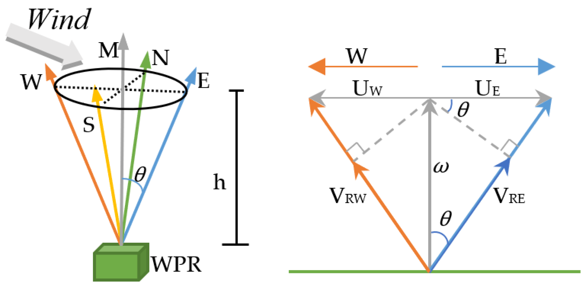
Assuming that the horizontal wind field is uniform and linear, according to the east-west plane schematic diagram of the five-beam WPR shown in Figure 5, we calculated the horizontal wind speeds in the east and west directions, using the following equations:
u E = V R E ω cos θ sin θ
u W = V R W ω cos θ sin θ
where V R W and V R E represent the radial wind speeds in the west and east directions, respectively; ω is the vertical radial speed; θ is the angle between the east and west beam and the vertical beam; and u E and u W represents the horizontal wind speed in the east and west directions, respectively.
If the radial wind speeds in the east and west directions are valid, the correct wind speed can be determined. In this study, we assumed that the atmospheric wind field was uniform; therefore, u E and u W were considered to be two vectors having the same magnitude, but opposite directions. Thus, the abovementioned equations could be expressed as follows:
u E = V R E V R W 2 sin θ
Similarly, the horizontal wind speed in the north direction was calculated, using the following equation:
v N = V R N V R S 2 sin θ
where V R N and V R S represent the radial wind speed in the north and south directions, respectively.

2.2.7. Median Test

The median test is the median judgment of the distance gate and the time of the data. If the offset of the current value is within a certain threshold of the median value, the value at that position should be retained. Otherwise, the value does not pass the median test and is considered invalid; it is replaced with the linear interpolation result. In this research, a 14-point neighborhood was used for the median test, and the arrangement is shown in Figure 6.
Notably, a median at a certain height and time can be obtained from 3 × 2, 4 × 2, 5 × 2, 3 × 3, or 5 × 3 space-time lattice points around its position in the data sequence in the following cases:
  • When the value is located at the double edges of the matrix, the lattice range can be set to 3 × 2. For example, the median at a1 in the figure was obtained from the median of [a1, b1, c1, d1, e1, f1].
  • When located in a single edge near the height axis, the lattice can be set to 4 × 2 or 5 × 2. For example, the position at b1 was obtained from [a1, b1, c1, b3, d1, e1, f1, e3] or [a1, b1, c1, b3, a3, d1, e1, f1, e3, d3].
  • When located in a single edge near the time axis, the lattice can be set to 3 × 3 or 4 × 3. For example, the position at d1 was obtained from [a1, b1, c1, d1, e1, f1, d2, e2, f2] or [a1, b1, c1, b3, d1, e1, f1, e3, d2, e2, f2, e4];
  • When located in the middle, the lattice can be set to 5 × 3. For example, the position at d1 was obtained from [a1, b1, c1, b3, a3, d1, e1, f1, e3, d3, d2, e2, f2, e4, d4].

3. Experiment and Result Verification

Based on the quality control method explained in Section 2, we used WPR data of CFL-06 at 00:35 h UTC in the southern suburbs of Beijing, China, on 3 June 2021, for quality control.
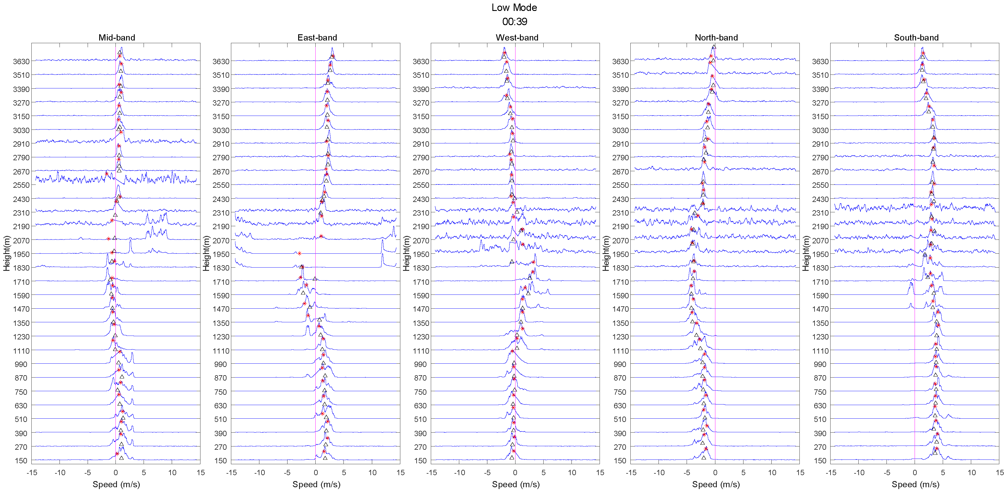
Figure 7 and Figure 8 portray the spectrum peak search results of the low and high modes. The red asterisks represent the identification results of our study, and the triangles represent the radar manufacturer’s instructions. As shown in the figures, our algorithm suppressed ground clutter effectively and retained the atmospheric turbulence echo near zero speed.
Additionally, our method could also correctly identify the noise and atmospheric turbulence echoes, thus, addressing the multipeak problem; moreover, the spectrum peak recognition results indicated better continuity and symmetry than that reported by the radar manufacturers.
Considering the low SNR at high heights, we appropriately reduced the SNR threshold in the high mode. The overall results portrayed that the accuracy was higher below 6 km.
Finally, we used the median filter proposed by Barbré to remove spurious Doppler spectral data and constrain the search for the atmospheric signal, and compared with this study and manufacturer.
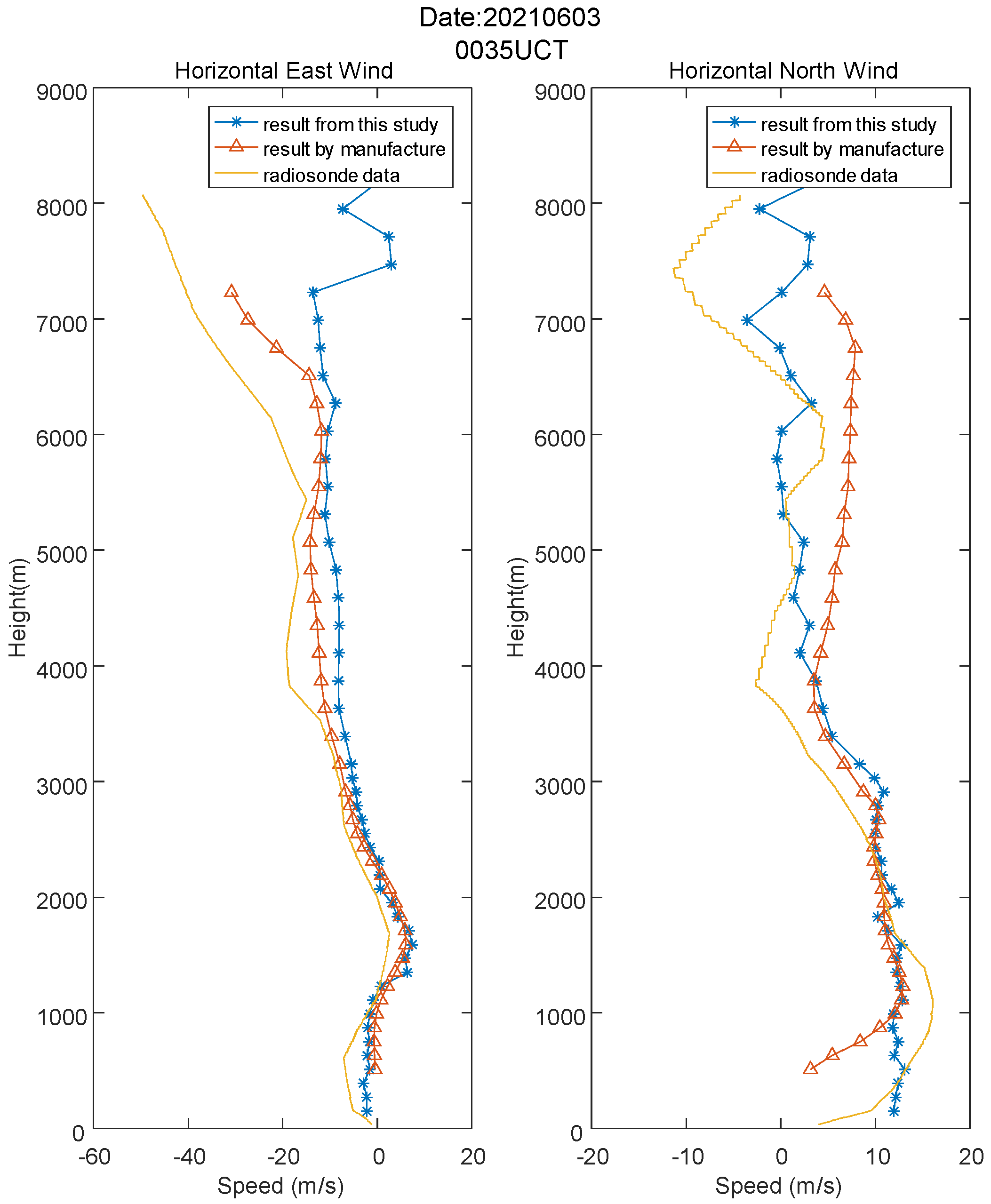
Figure 9 portrays the horizontal wind-speed results obtained after the profiling process. The horizontal wind speed was divided into east and north axes. The solid, triangular, and asterisk lines represent the results obtained by radiosonde, the manufacturer, and this study, respectively. The quality control effect of our algorithm was satisfactory and consistent with that of radiosonde, and the error values were within 5 m/s below 6 km and 2 m/s below 3.5 km. Notably, the north-axis error between 4 km and 6 km was obviously better than that reported by the manufacturer.
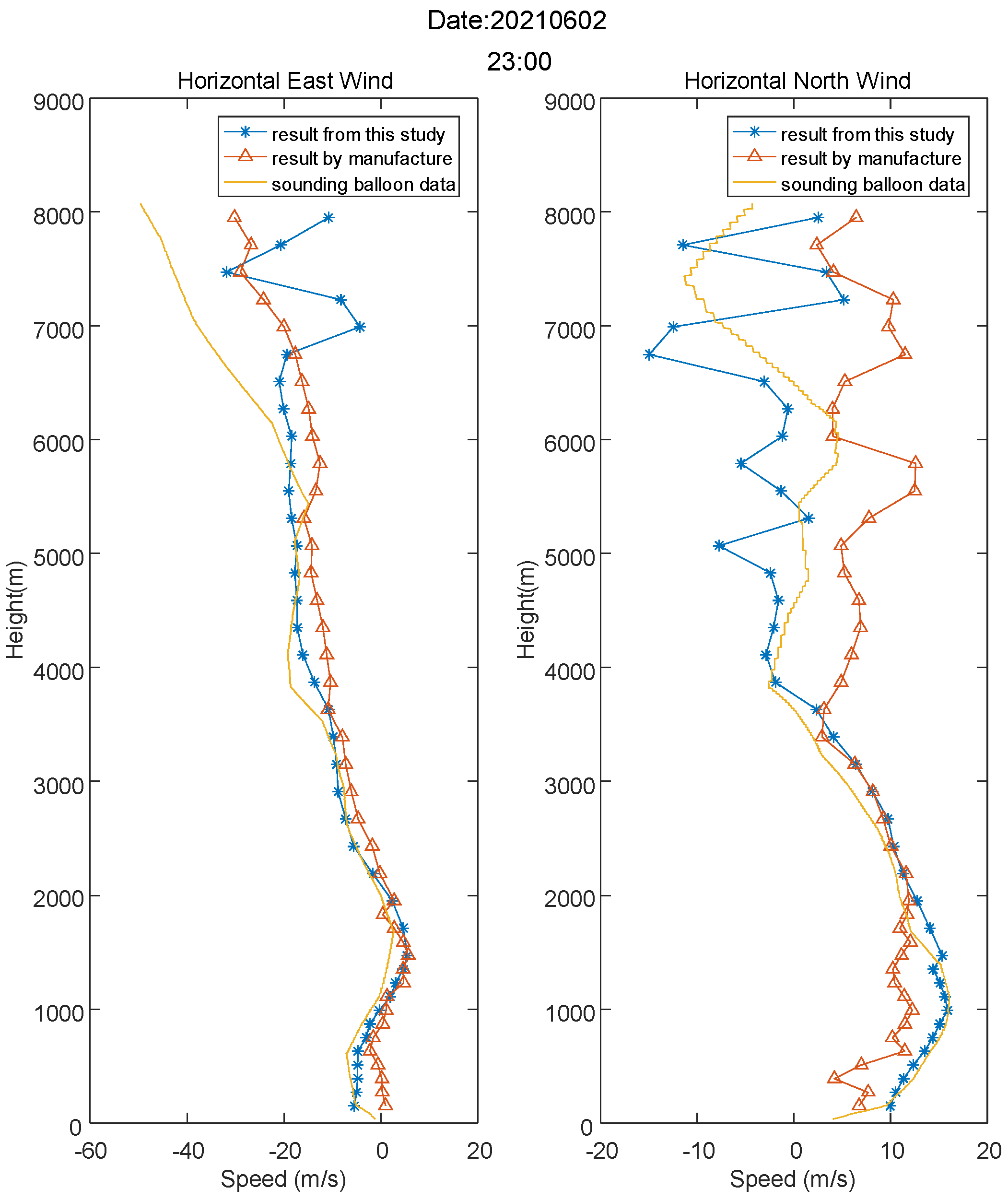
To verify the universality of this study, we repeated the process using TWP8 WPR data at 23:00 h UTC from Beijing, China, on 2 June 2021.
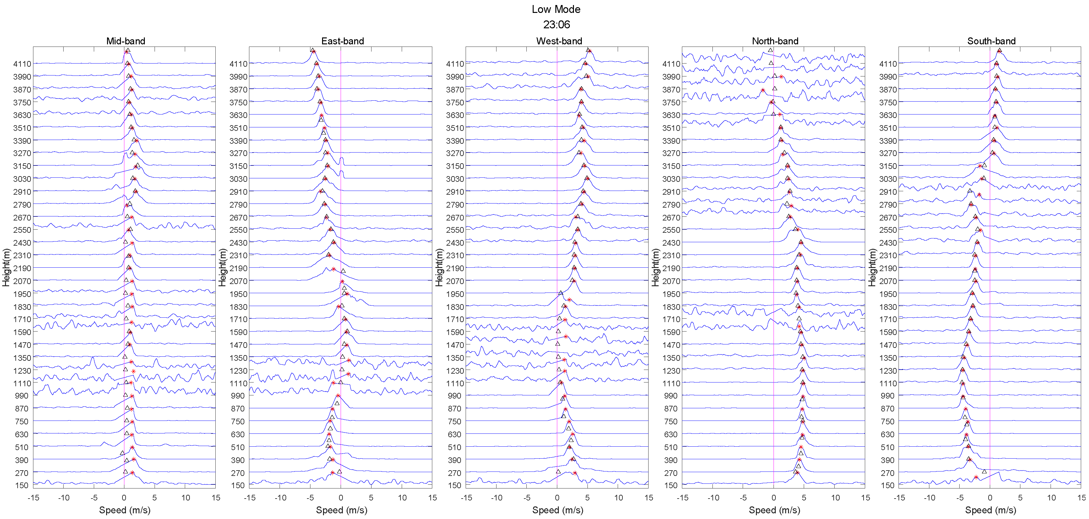
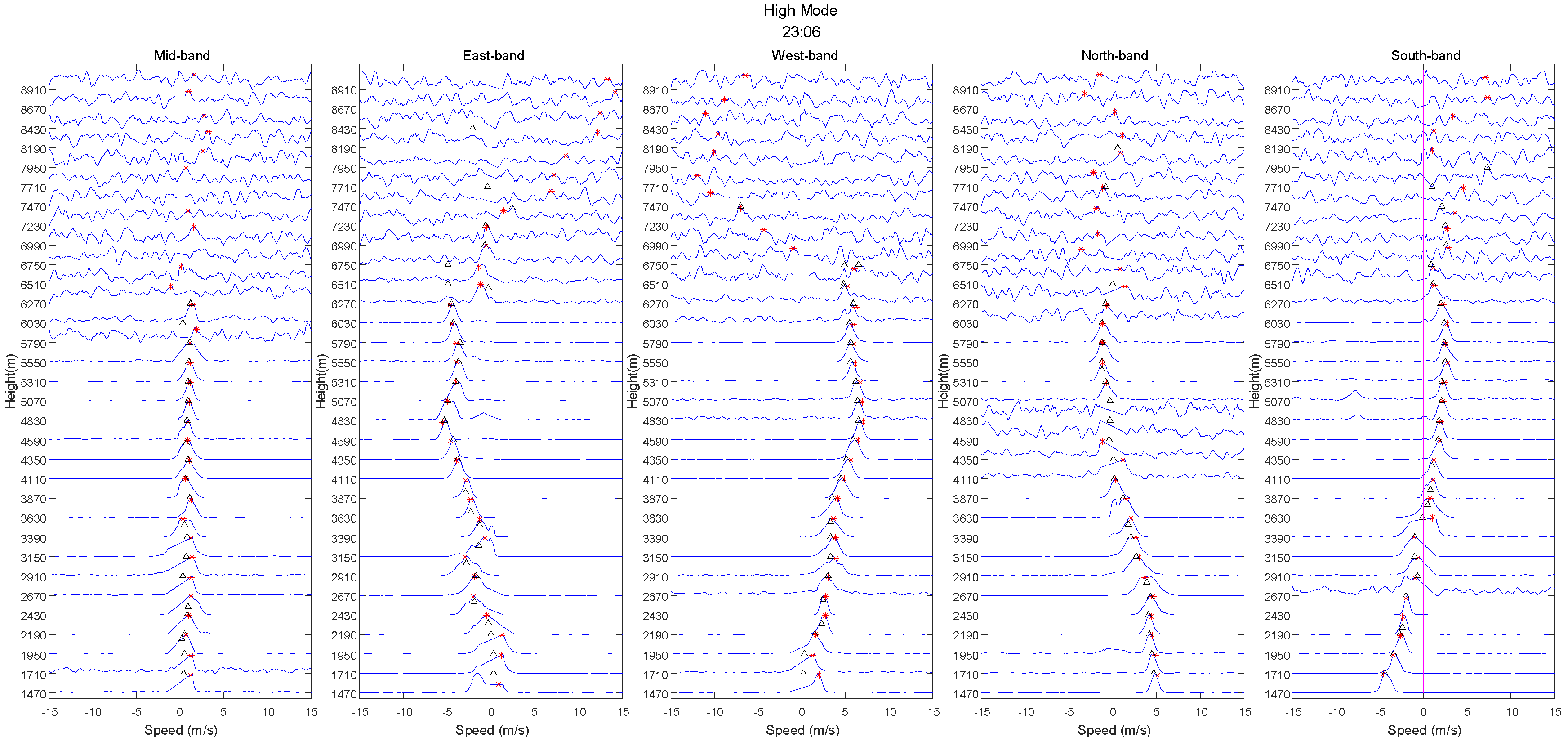
Figure 10 and Figure 11 portray the spectrum peak recognition in the low and high modes, and the symbols are consistent with those in previous figures. Compared with CFL-06, the SNR of TWP8 was higher, the ground clutter was relatively wider, and other interference types were relatively fewer. As shown in the figures, in the same ground clutter and multipeak conditions, the spectrum peak recognition in this study also indicated good continuity and symmetry. However, the SNR of the sign mode above 6 km was too low to identify the correct atmospheric echo.
As shown in Figure 12, the results of this study on both the axes below 6.8 km were better than those of the manufacturer, especially from 4 km to 6.8 km on the east axis and below 4 km on the north axis.
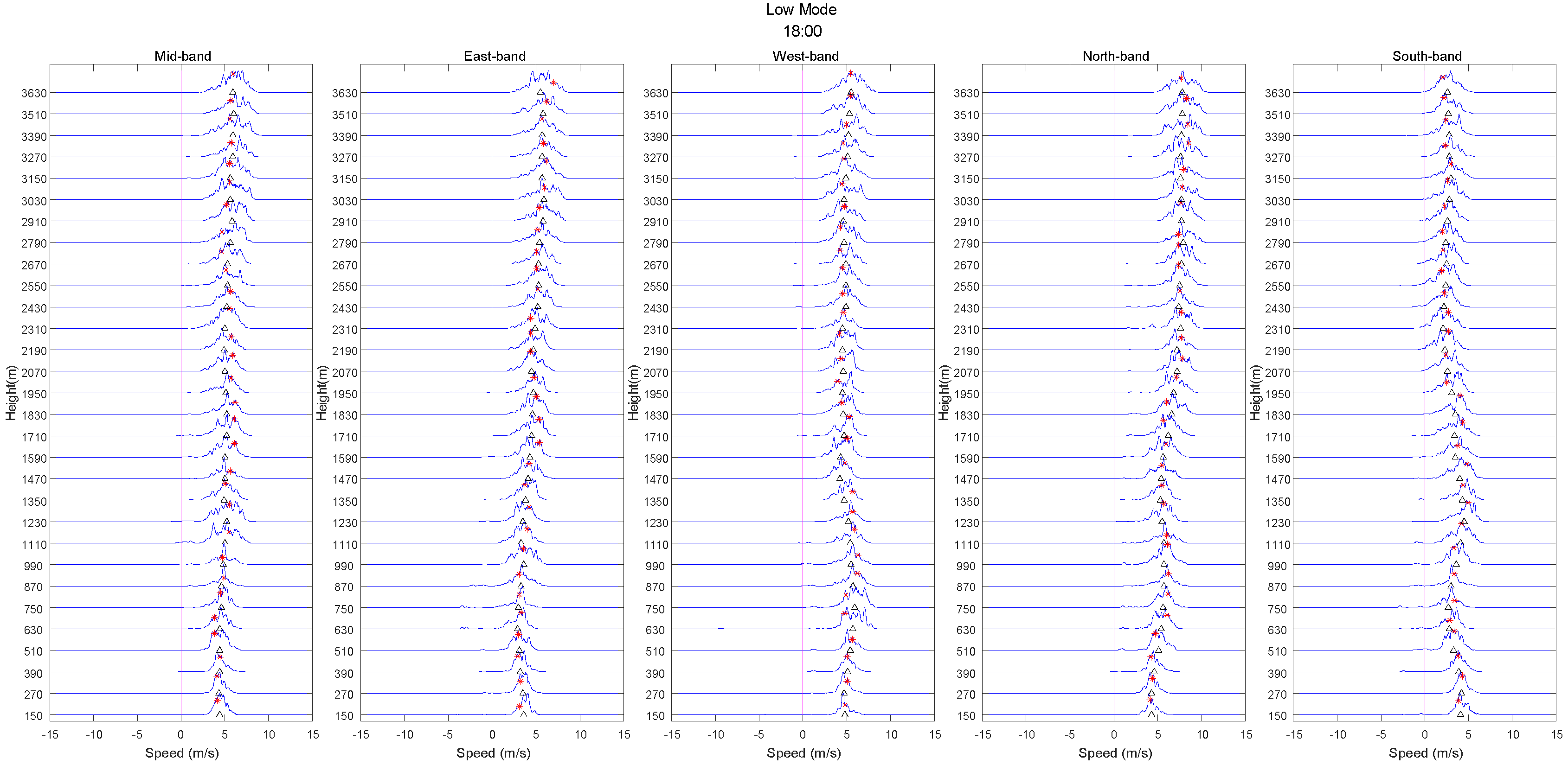
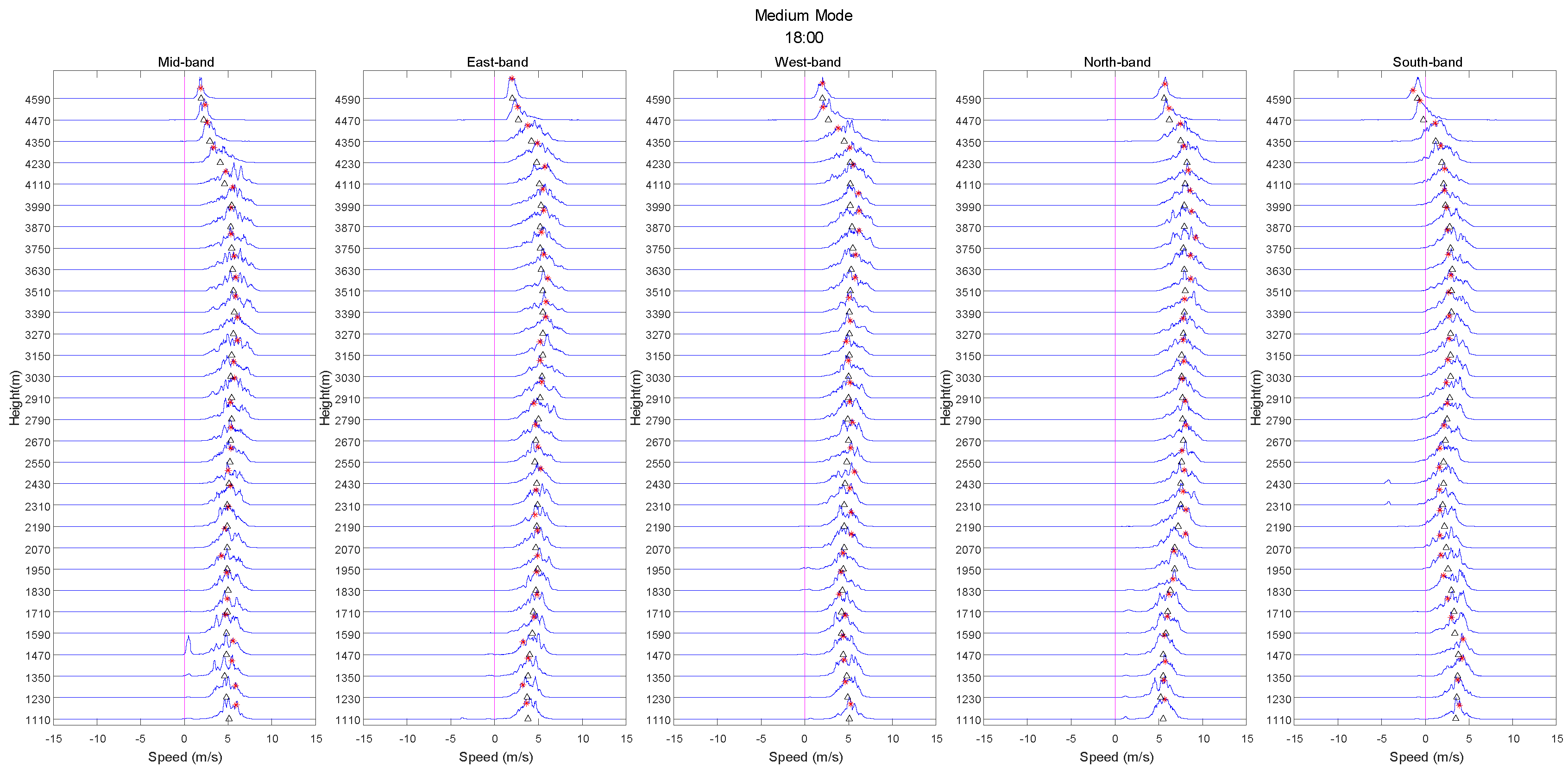
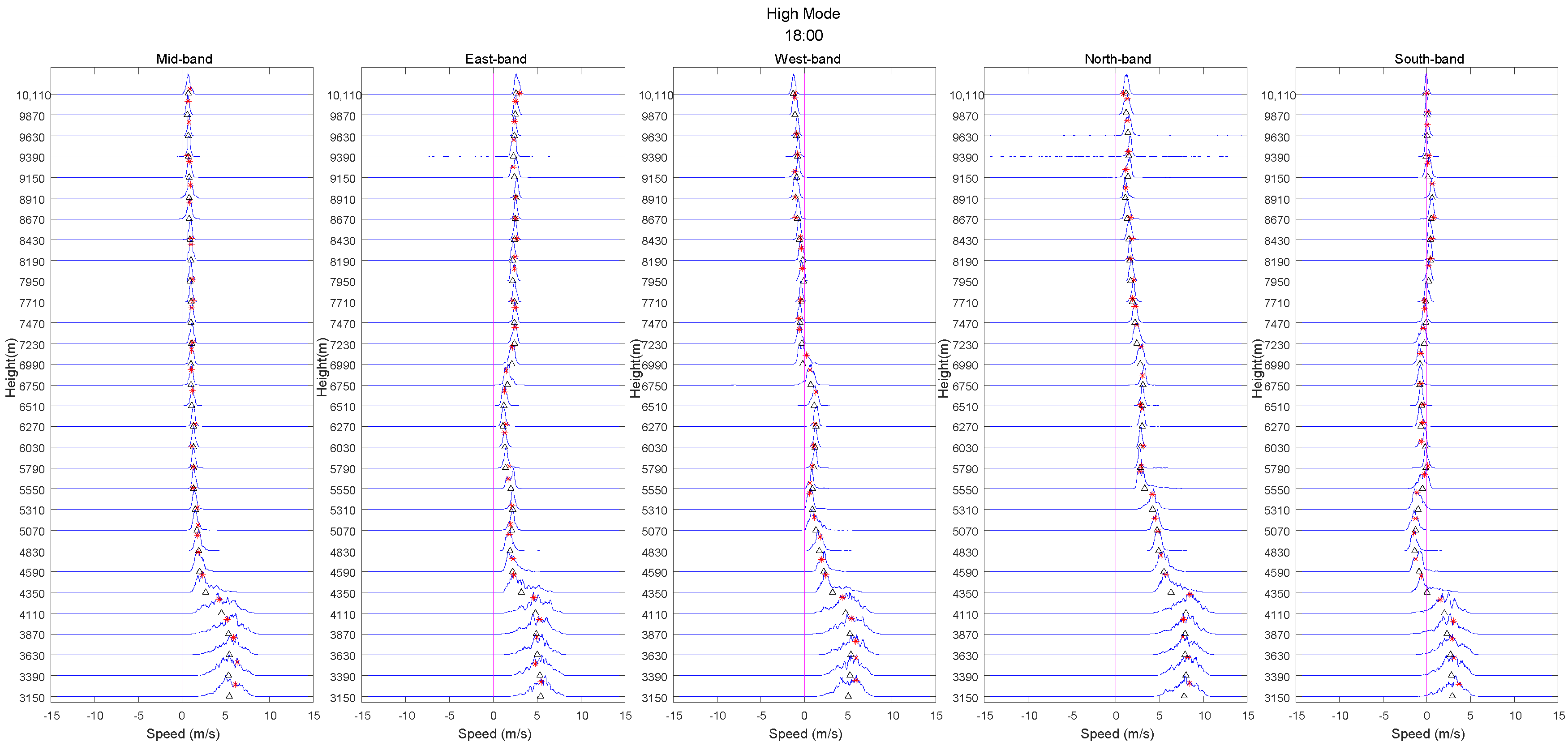
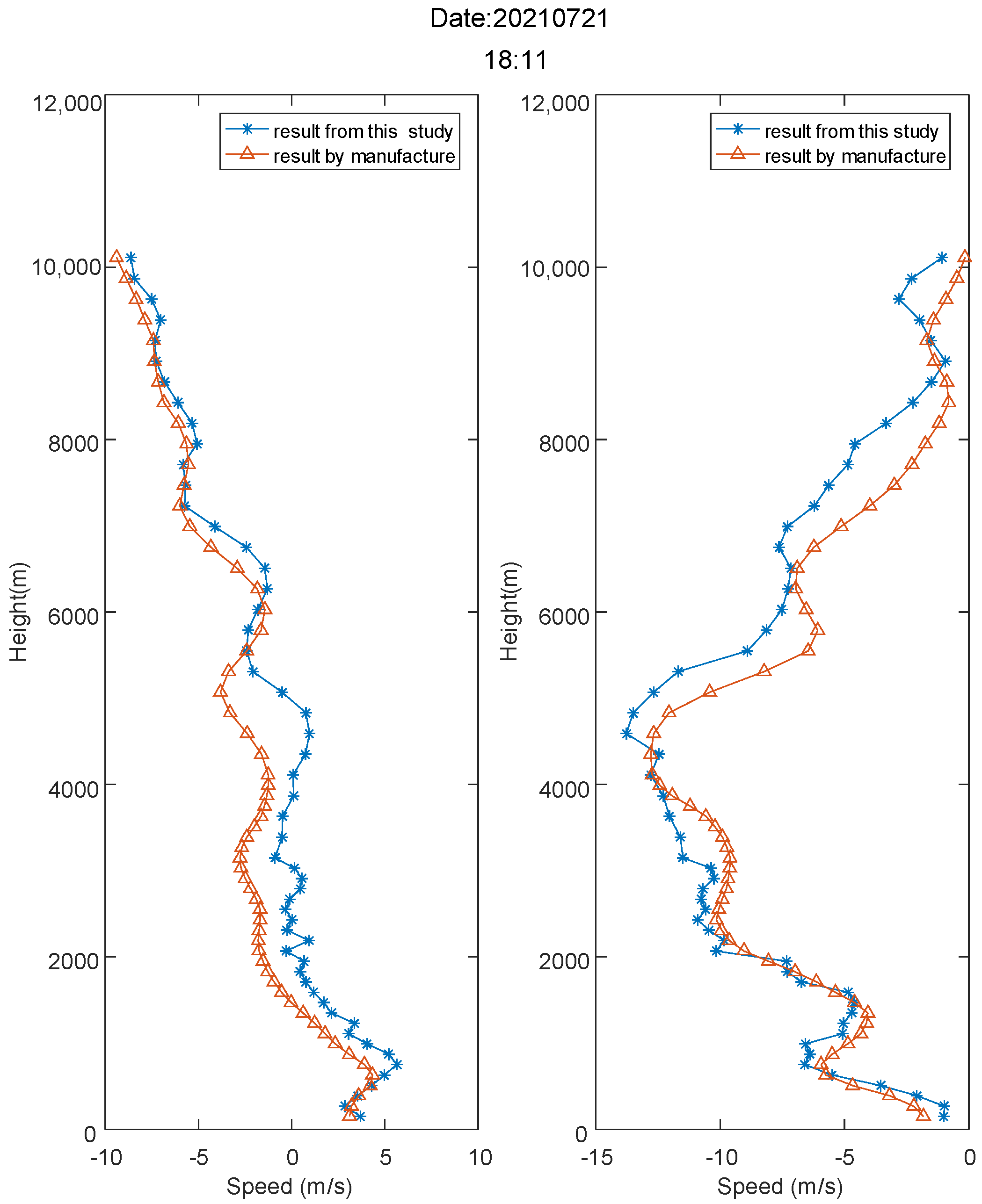
For precipitation, we selected the basic data obtained from the CFL-06 radar in Huairou, Beijing, China, on 21 July 2021. According to the China Weather Network, precipitation occurred at 18:00 h on this date; therefore, we selected the data recorded around that time. To adapt to complex environments, the CFL-06 radar was designed with three work modes (low, middle, and high). The spectrum peak recognition results for each mode are shown in Figure 13, Figure 14 and Figure 15.
As shown in Figure 13, Figure 14 and Figure 15, the atmospheric echo signals were strong and the other interferences were relatively weak; these conditions were helpful for algorithm verification. Although the atmospheric echo above 5 km in the south band was located very close to the zero-speed line, this echo was not recognized as ground clutter. Therefore, the spectrum peak recognition results of this study indicated good continuity. Because radiosonde data were not available at the time, we only compared our results with those of the radar manufacturer. Figure 16 shows the horizontal wind speed.
According to the comparison, below 10 km, the results of this study were consistent with those of the manufacturer.
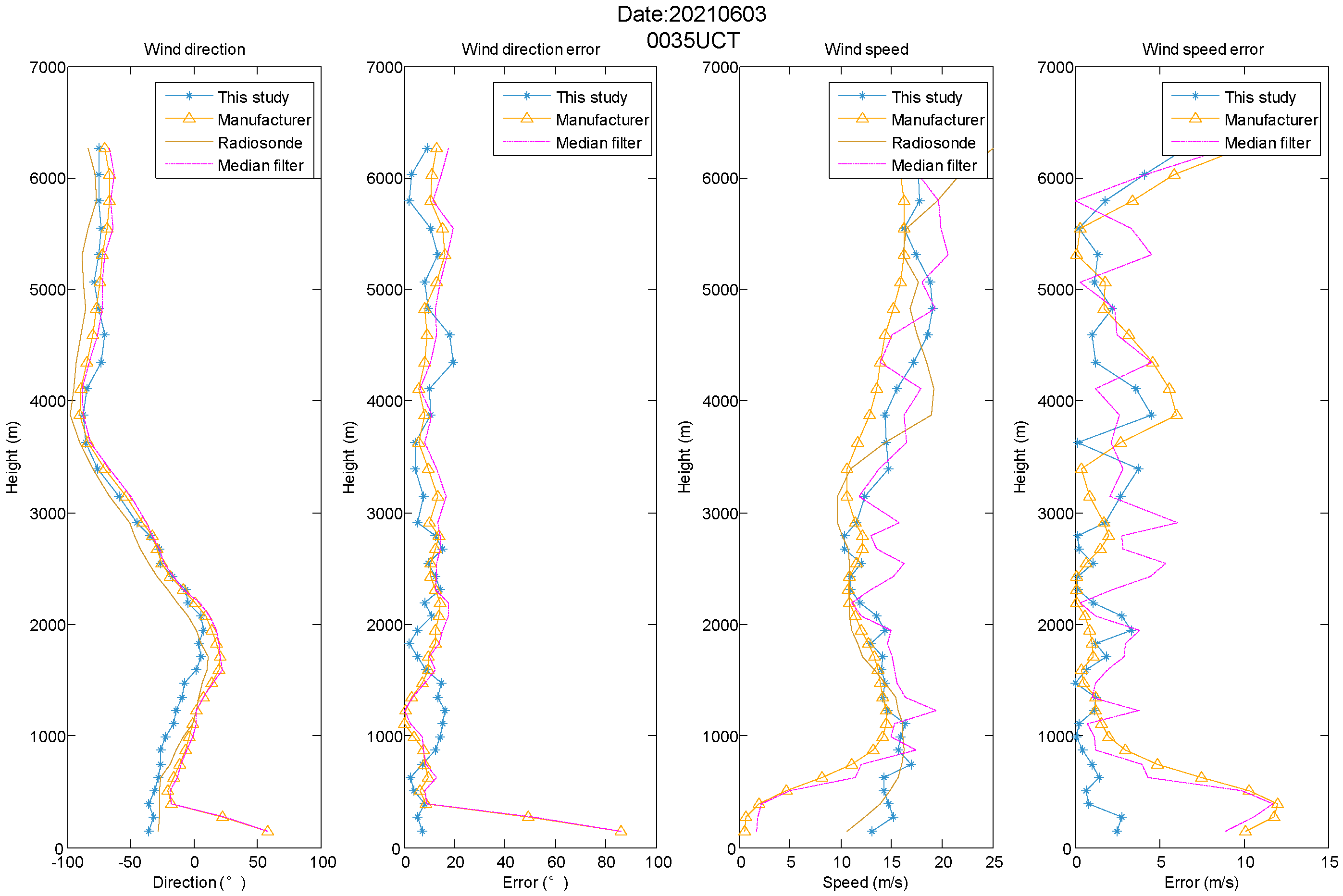
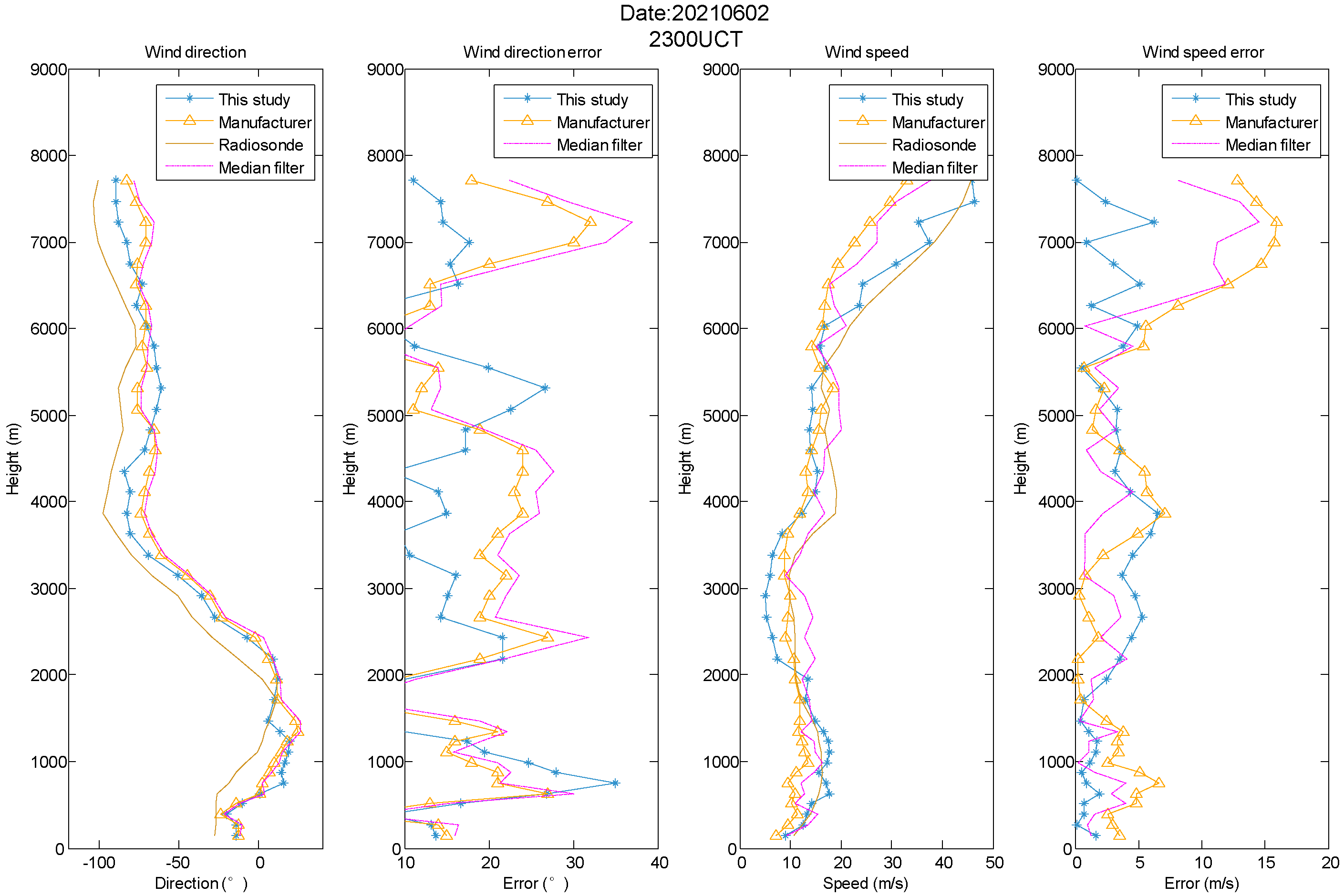
Finally, we compared the errors in the CFL-06 and TWP8 radar data in Figure 9 and Figure 12, as shown in Figure 17 and Table 1, Figure 18, and Table 2, respectively.

4. Result and Discussion

In clear-sky conditions below a height of 6 km, the process results of our study were closer to the radiosonde data and better than the manufacturer’s and the median filter results. However, above 6 km, the results of the manufacturer and those calculated in our study were different from the radiosonde data, because the limited SNR of the upper atmospheric echo resulted in a lower detection accuracy in step 2 (spectrum peak search).
In precipitation conditions, because of the strong SNR of the reflected echo, the detection height of the WPR was 10 km. Because radiosonde data were not available, we only conducted a comparative experiment between the manufacturer’s and our algorithm and obtained good consistency. Notably, the quality control results of our study were close to that of the manufacturer and presented an error of less than 2 m/s, thus demonstrating the validity of our method.
According to the error values shown in Figure 17 and Figure 18 and Table 1 and Table 2, we obtained a similar set of values along with the whole height of the wind profile, while observing an acceptable error along with the height. Significantly, we achieved remarkable results below 1.5 km on both CFL-06 radar and TWP8 radar, compared with that of the manufacturer and the median filter algorithm. Thus, the method of this study was useful for suppressing ground clutter and the results were superior to those of the manufacturer and the median filter as a whole.
Notably, our results indicate the following accomplishments:
  • The quality control process proposed in this study was effective and suitable for the two types of WPR used in the experiment and may be extended to other radars in the future.
  • The algorithm flow could control the quality of the WPR data, regardless of clear-sky or precipitation conditions.
  • When the SNR was small, the quality control effect was not evident and the data quality result of the WPR continued to be restricted by the SNR of the echo.
The main contributions of this study are as follows:
  • A complete quality control process for WPR data was proposed;
  • The spectral line and contour line were combined for quality control using a variety of fusion algorithms;
  • The minimum connections method was proposed for clutter suppression, and the reproduction peak-searching symmetry was introduced in the judgment process during spectrum quality control.
  • The median test algorithm was used to optimize the wind-speed calculation results and obtain better results.
  • A comparison experiment was carried out to consider different weather conditions and multiple WPRs.
Additionally, the future direction of our study is explained below:
  • In the future, we will focus on optimizing the quality control algorithm for WPRs when the SNR is weak, while applying a variety of methods to compare the research results.
  • In this study, we only performed quality control of the base data (power spectrum and primary speed). However, quality control is also important for secondary products (such as turbulence intensity, temperature, and wind shear) generated from primary speed. In future studies, we plan to extend the quality control algorithm to the secondary products of the wind profiler to improve the effectiveness of the radar.

5. Conclusions

Based on previous studies, we established a complete algorithm flow to address the difficulty of performing data quality control for WPRs. A fusion method of various quality control algorithms (including noise filtering, ground object clutter suppression, spectrum peak search, and result inspection) was proposed in this study. Two different types of WPRs and radiosonde data were selected for comparison and verification in the experiment. The results indicated that in different weather conditions and using different WPRs, the essence control algorithm had better continuity and symmetry, compared with the traditional quality control method used by the manufacturers. Therefore, the WPR quality control process proposed in this study can be applied to different weather conditions and adapted to different WPR data quality control processes, to improve the accuracy and reliability of WPR products.

Author Contributions

Conceptualization, data curation, formal analysis, investigation, methodology, software, writing—original draft, funding acquisition, Y.Q.; resources, supervision, writing—review and editing, Y.G. All authors have read and agreed to the published version of the manuscript.

Funding

This research was funded by the National Natural Science Foundation of China, grant number U1733103.

Institutional Review Board Statement

Not applicable.

Informed Consent Statement

Not applicable.

Data Availability Statement

The datasets supporting the conclusions of this article are private, and it came from the CMA Key Laboratory of Atmospheric Sounding, Chengdu, Sichuan, China and the Key Laboratory of Earth Exploration and Information Techniques, Ministry of Education, China.

Conflicts of Interest

The authors declare no conflict of interest.

References

  1. Cohn, S.A.; Brown, W.; Martin, C.L.; Susedik, M.E.; Maclean, G.D.; Parsons, D. Clear air boundary layer spaced antenna wind measurement with the Multiple Antenna Profiler (MAPR). Ann. Geophys. 2001, 19, 845–854. [Google Scholar] [CrossRef] [Green Version]
  2. Cohn, S.A.; Holloway, C.L.; Oncley, S.P.; Doviak, R.J.; Lataitis, R.J. Validation of a UHF spaced antenna wind profiler for high-resolution boundary layer observations. Radio Sci. 1997, 32, 1279–1296. [Google Scholar] [CrossRef]
  3. Lau, E.; Mclaughlin, S.; Pratte, F.; Weber, B.; Merritt, D.; Wise, M.; Zimmerman, G.; James, M.; Sloan, M. The DeTect Inc. RAPTOR VAD-BL Radar Wind Profiler. J. Atmos. Ocean. Technol. 2013, 30, 1978–1984. [Google Scholar] [CrossRef]
  4. May, P.T.; Keenan, T.D. Evaluation of Microphysical Retrievals from Polarimetric Radar with Wind Profiler Data. J. Appl. Meteorol. 2010, 44, 827–838. [Google Scholar] [CrossRef]
  5. Merceret, F.J. Rapid Temporal Changes of Boundary Layer Winds. J. Appl. Meteorol. Climatol. 2006, 45, 1016–1020. [Google Scholar] [CrossRef]
  6. Dolman, B.K.; Reid, I.M.; Tingwell, C. Stratospheric tropospheric wind profiling radars in the Australian network. Earth Planets Space 2018, 70, 170. [Google Scholar] [CrossRef] [Green Version]
  7. Gage, K.S.; Williams, C.R.; Clark, W.L.; Johnston, P.E.; Carter, D.A. Profiler Contributions to Tropical Rainfall Measuring Mission (TRMM) Ground Validation Field Campaigns. J. Atmos. Ocean. Technol. 2002, 19, 843–863. [Google Scholar] [CrossRef]
  8. Hartten, L.M.; Johnston, P.E. Stratocumulus-Topped Marine Boundary Layer Processes Revealed by the Absence of Profiler Reflectivity. J. Appl. Meteorol. Climatol. 2012, 53, 1775–1789. [Google Scholar] [CrossRef]
  9. Su, C.L. Intercomparisons of Tropospheric Wind Velocities Measured by Multi-Frequency Wind Profilers and Rawinsonde. Atmosphere 2021, 12, 1284. [Google Scholar]
  10. Cohn, S.A.; Goodrich, R.K. Radar Wind Profiler Radial Velocity: A Comparison with Doppler Lidar. J. Appl. Meteorol. 2002, 41, 1277–1282. [Google Scholar] [CrossRef]
  11. Ishihara, M. Characteristics and performance of the operational wind profiler network of the Japan Meteorological Agency. J. Meteorol. Soc. Jpn. Ser. II 2006, 84, 1085–1096. [Google Scholar] [CrossRef] [Green Version]
  12. Petitdidier, M.; Sy, A.; Garrouste, A.; Delcourt, J. Statistical characteristics of the noise power spectral density in UHF and VHF wind profilers. Radio Sci. 2016, 32, 1229–1247. [Google Scholar] [CrossRef]
  13. Samson, T.K.; Kottayil, A.; Manoj, M.G.; Binoy, B.; Rakesh, V.; Rebello, R.; Vasudevan, K.; Mohanan, P.; Santosh, K.R.; Mohankumar, K. Technical Aspects of 205 MHz VHF Mini Wind Profiler Radar for Tropospheric Probing. IEEE Geosci. Remote Sens. Lett. 2016, 13, 1027–1031. [Google Scholar] [CrossRef]
  14. Lottman, B.T.; Frehlich, R.G. Evaluation of Doppler radar velocity estimators. Radio Sci. 2016, 32, 677–686. [Google Scholar] [CrossRef]
  15. Hooper, D.A.; Nash, J.; Oakley, T.; Turp, M. Validation of a new signal processing scheme for the MST radar at Aberystwyth. Ann. Geophys. 2008, 26, 3253–3268. [Google Scholar] [CrossRef] [Green Version]
  16. Lehmann, V.; Teschke, G. Wavelet based methods for improved wind profiler signal processing. Ann. Geophys. 2001, 19, 825–836. [Google Scholar] [CrossRef]
  17. Lehmann, V.; Teschke, G. Advanced intermittent clutter filtering for radar wind profiler: Signal separation through a Gabor frame expansion and its statistics. Ann. Geophys. 2008, 26, 759–783. [Google Scholar] [CrossRef] [Green Version]
  18. Lehmann, V. Optimal Gabor-Frame-Expansion-Based Intermittent-Clutter-Filtering Method for Radar Wind Profiler. J. Atmos. Ocean. Technol. 2012, 29, 141–158. [Google Scholar] [CrossRef]
  19. Bianco, L.; Gottas, D.; Wilczak, J.M. Implementation of a Gabor Transform Data Quality-Control Algorithm for UHF Wind Profiling Radars. J. Atmos. Ocean. Technol. 2013, 30, 2697–2703. [Google Scholar] [CrossRef]
  20. Chen, Y.W.; Mendoza, N.E.; Nakao, Z.; Adachi, T. Estimating wind speed in the lower atmosphere wind profiler based on a genetic algorithm. IEEE Trans. Instrum. Meas. 2002, 51, 593–597. [Google Scholar] [CrossRef]
  21. Hashimoto, T.; Nishimura, K.; Tsutsumi, M.; Sato, K.; Sato, T. A User Parameter-Free Diagonal-Loading Scheme for Clutter Rejection on Radar Wind Profilers. J. Atmos. Ocean. Technol. 2017, 34, 1139–1153. [Google Scholar] [CrossRef] [Green Version]
  22. Salonen, K.; Haase, G.; Eresmaa, R.; Hohti, H.; Jarvinen, H. Towards the operational use of Doppler radar radial winds in HIRLAM. Atmos. Res. 2011, 100, 190–200. [Google Scholar] [CrossRef]
  23. May, P.T.; Cummings, F.; Koutsovasilis, J. The Australian Bureau of Meteorology 1280-MHz Wind Profiler. J. Atmos. Ocean. Technol. 2002, 19, 911–923. [Google Scholar] [CrossRef]
  24. Barbré, R.E., Jr. Quality Control Algorithms for the Kennedy Space Center 50-Megahertz Doppler Radar 2 Wind Profiler Winds Database. J. Atmos. Ocean. Technol. 2012, 29, 1731–1743. [Google Scholar] [CrossRef]
  25. Kumar, S.; Rao, T.N.; Rao, M.D.; Kamaraj, P. Multi-Receiver Augmentation to Advanced Indian MST Radar (AIR)-Implementation of Spaced Antenna Technique. Radio Sci. 2021, 56, e2021RS007263. [Google Scholar] [CrossRef]
  26. Zhang, Y.; Chen, M.; Zhong, J. A Quality Control Method for Wind Profiler Observations toward Assimilation Applications. J. Atmos. Ocean. Technol. 2017, 34, 1591–1606. [Google Scholar] [CrossRef]
  27. Nehrkorn, T. Analysis and Quality Control of Profiler Data Using Optimum Interpolation. J. Atmos. Ocean. Technol. 2000, 17, 651–655. [Google Scholar] [CrossRef]
  28. Ecklund, W.L.; Gage, K.S.; Williams, C.R. Tropical precipitation studies using a 915-MHz wind profiler. Radio Sci. 1995, 30, 1055–1064. [Google Scholar] [CrossRef]
  29. Lambert, W.C.; Merceret, F.J.; Taylor, G.E.; Ward, J.G. Performance of five 915-MHz wind profilers and an associated automated quality control algorithm in an operational environment. J. Atmos. Ocean. Technol. 2003, 20, 1488–1495. [Google Scholar] [CrossRef] [Green Version]
Figure 1. Process of wind profile radar data quality control.
Atmosphere 13 00796 g001
Figure 2. Power spectrum of the first range gate in the south direction: (a) before and (b) after ground clutter suppression.
Atmosphere 13 00796 g002
Figure 3. Superposition distribution of clear sky data and precipitation disturbed data by (a) CFL-06 and (b) TWP8 (vertical radial speed and signal-to-noise ratio).
Atmosphere 13 00796 g003
Figure 4. Low-mode power spectrum by multipeak processing in the (a) north (b) south bands.
Atmosphere 13 00796 g004
Figure 5. Schematic plan view of the five-beam wind profiler radar (WPR) in the east and west directions.
Atmosphere 13 00796 g005
Figure 6. Neighborhood space-time lattice points.
Atmosphere 13 00796 g006
Figure 7. Results of spectrum peak recognition in CFL-06 low mode.
Atmosphere 13 00796 g007
Figure 8. Results of spectrum peak recognition in CFL-06 high mode.
Atmosphere 13 00796 g008
Figure 9. Wind profile of CFL-06.
Atmosphere 13 00796 g009
Figure 10. Spectrum peak recognition results in TWP8 low mode.
Atmosphere 13 00796 g010
Figure 11. Spectrum peak recognition results in TWP8 high mode.
Atmosphere 13 00796 g011
Figure 12. Wind profile of TWP8.
Atmosphere 13 00796 g012
Figure 13. Recognition results of spectrum peak in low model during precipitation.
Atmosphere 13 00796 g013
Figure 14. Recognition results of spectrum peak in middle model during precipitation.
Atmosphere 13 00796 g014
Figure 15. Recognition results of spectrum peak in high model during precipitation.
Atmosphere 13 00796 g015
Figure 16. Wind profile during precipitation.
Atmosphere 13 00796 g016
Figure 17. Wind profile and errors by our method, median filter algorithm, and those from the manufacturer: CFL-06 radar data were compared with radiosonde data.
Atmosphere 13 00796 g017
Figure 18. Wind profile and errors by our method, median filter algorithm and those from the manufacturer: TWP8 radar data were compared with radiosonde data.
Atmosphere 13 00796 g018
Table 1. Maximum values of errors based on our method and those from the manufacturer in clear-sky conditions: CFL-06 radar data were compared with radiosonde data.
Height (km)<1.51.5–3.53.5–6
Direction (°)this study16.514.617.1
manufacturer85.213.216.5
media filter87.515.316.7
Speed (m/s)this study3.24.24.7
manufacturer12.22.87.3
media filter9.75.15.5
Values significantly better than that of the manufacturer are given in blue.
Table 2. Maximum values of errors based on our method and those from the manufacturer in clear-sky conditions: TWP8 radar data were compared with radiosonde data.
Height (km)<1.51.5–3.53.5–7.6
Direction (°)this study37.221.325.6
manufacturer29.128.836.8
media filter29.832.537.3
Speed (m/s)this study2.26.56.2
manufacturer7.22.417.2
media filter4.84.913.4
Values significantly better than that of the manufacturer are given in blue.
Publisher’s Note: MDPI stays neutral with regard to jurisdictional claims in published maps and institutional affiliations.