
Study of an Asymmetric and Anticyclonic Bow Echo Near Taiwan


Abstract
1. Introduction
2. Data, Methodology, and Numerical Experiment
2.1. Data and Methodology
2.2. The CReSS Model and the Experiment
2.3. Vorticity Budget Diagnosis
3. Case Overview
3.1. Synoptic and Thermodynamic Conditions
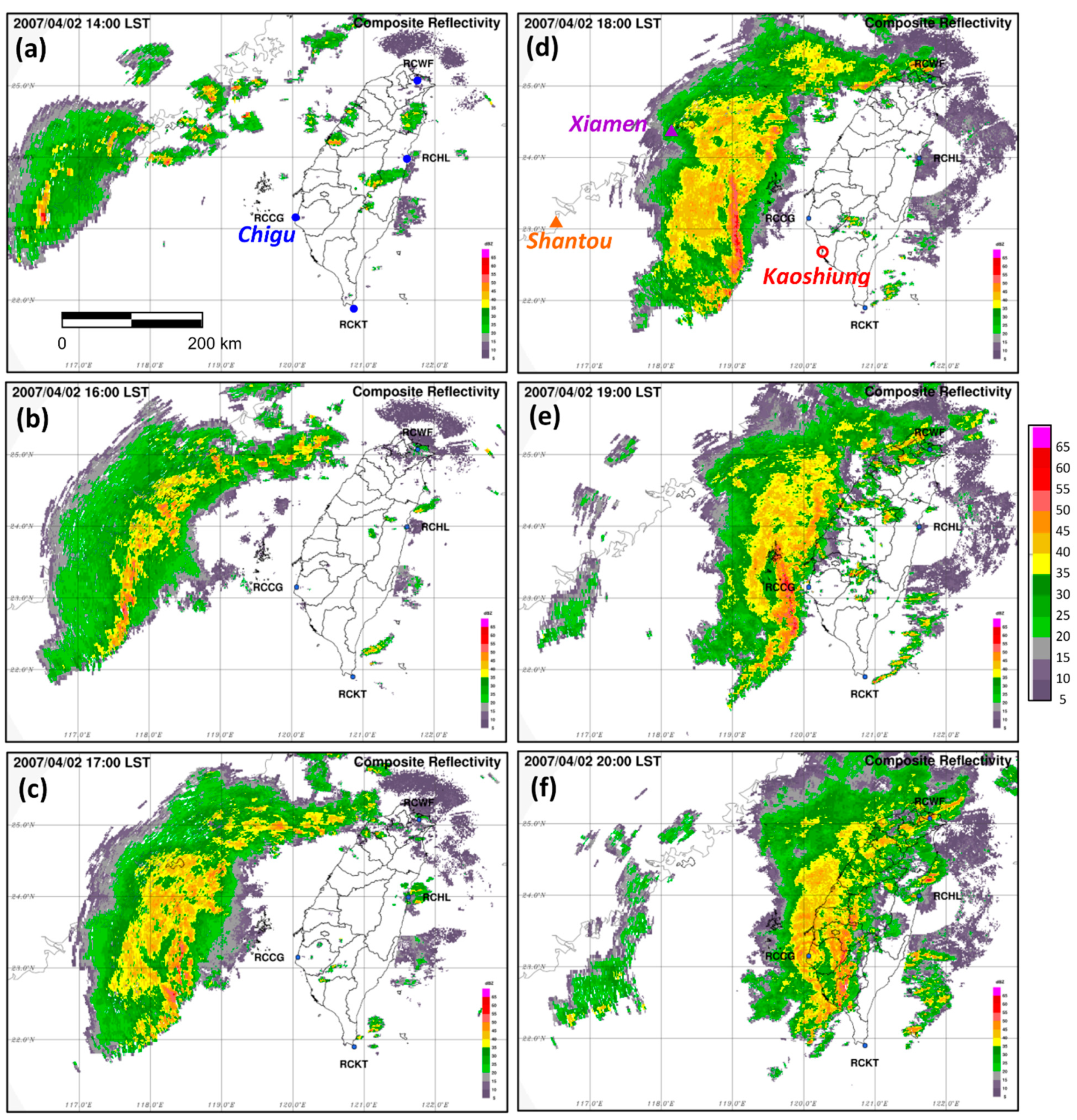
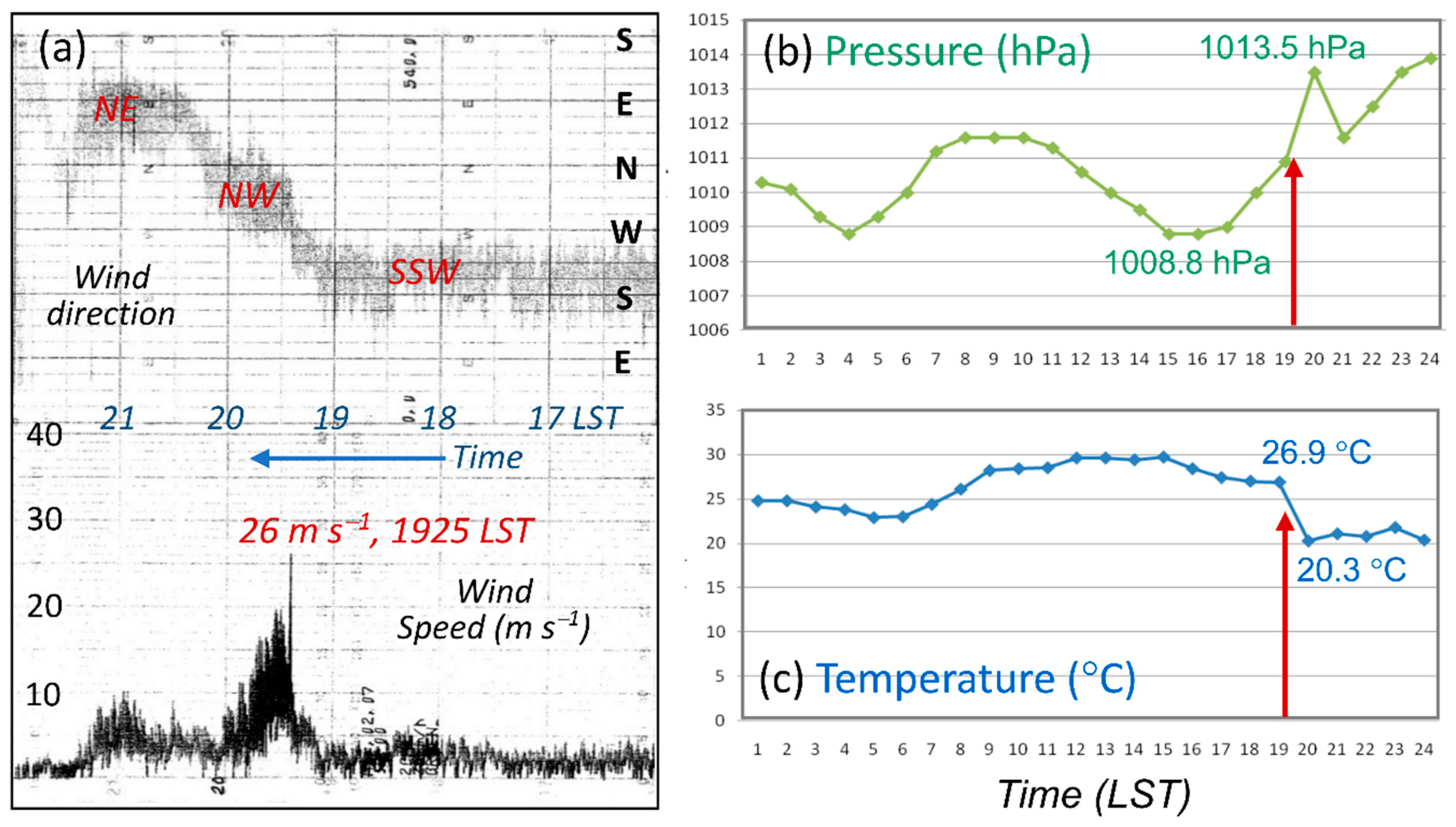
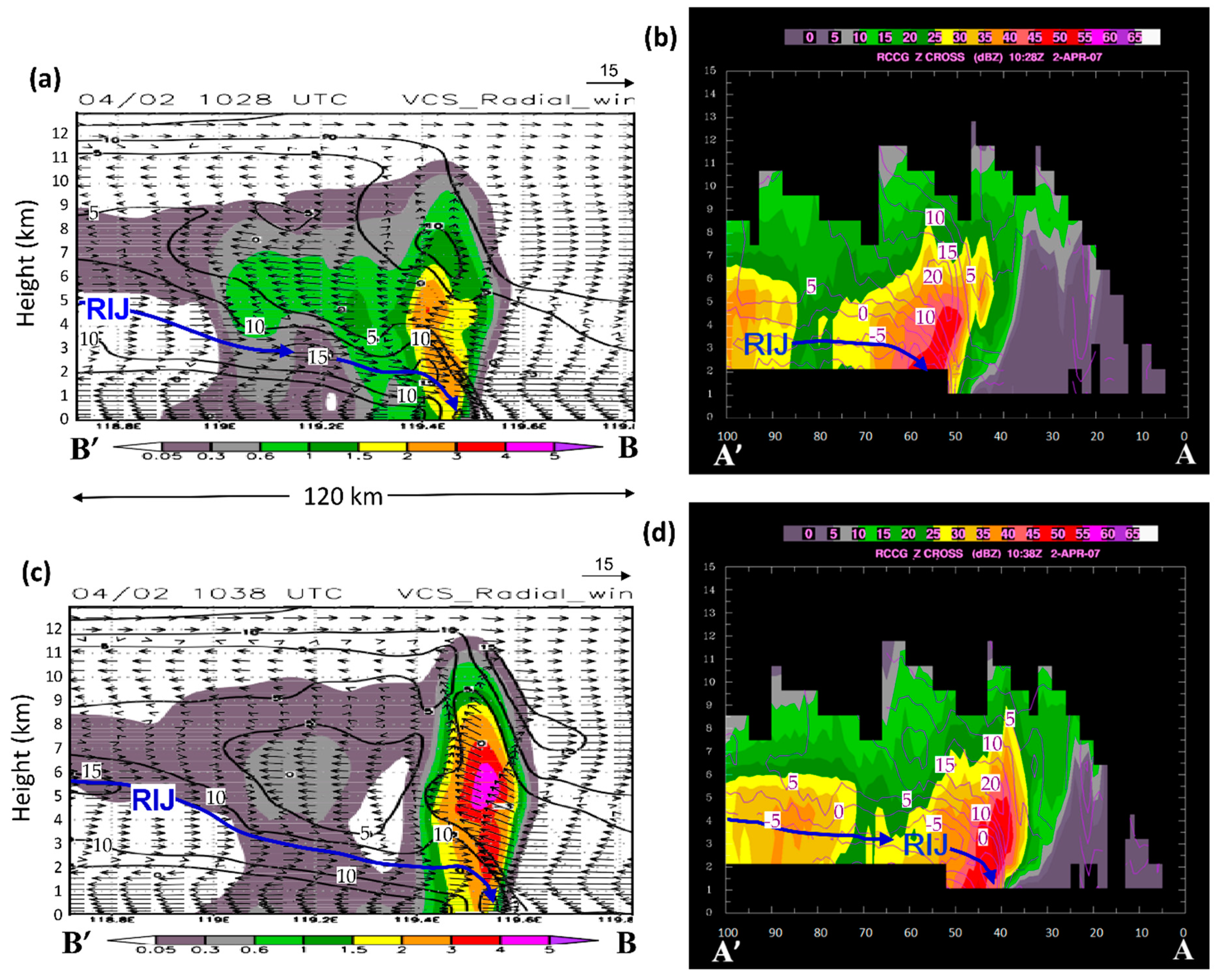
3.2. Evolution of the Bow Echo and Associated Weather
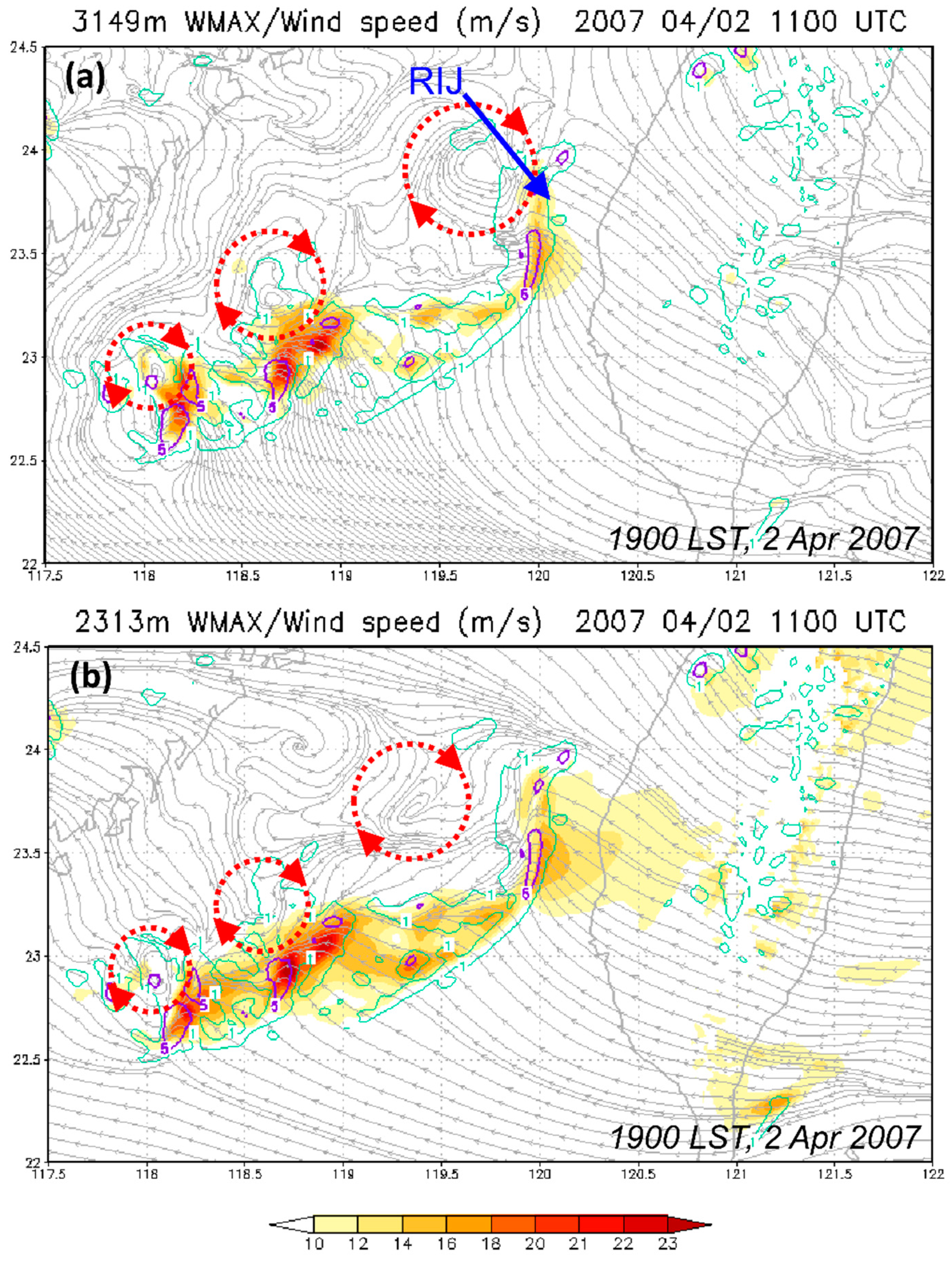
3.3. Asymmetric and Anticyclonic Structure of the Bow Echo
4. Results of Numerical Experiment
4.1. Model Results and Validation
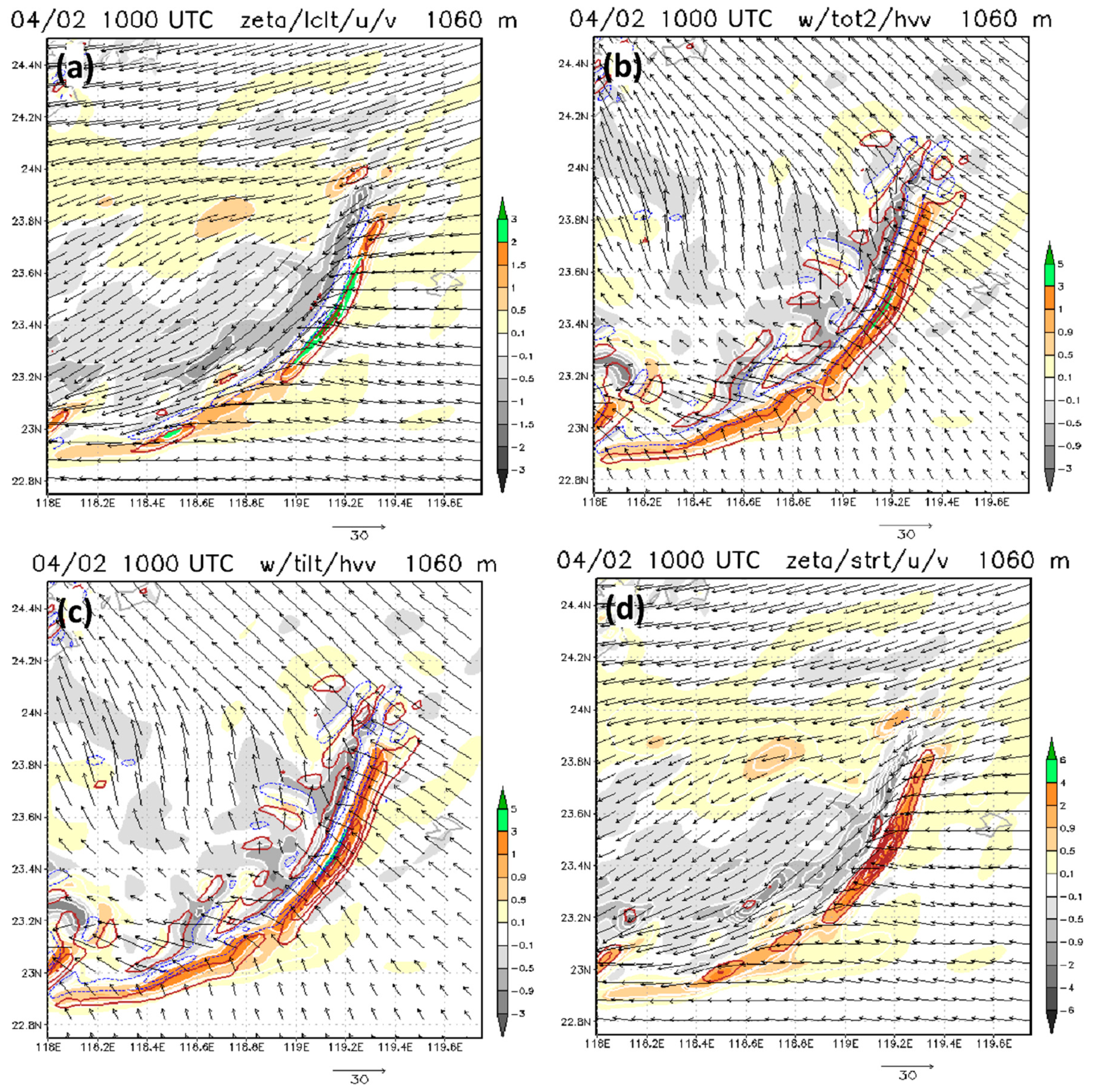
4.2. Structure of the Anticyclonic Bow Echo
5. Vorticity Budget Diagnosis on the Bow Echo
6. Conclusions
Author Contributions
Funding
Institutional Review Board Statement
Informed Consent Statement
Data Availability Statement
Acknowledgments
Conflicts of Interest
References
- Glickman, T.S. (Ed.) Glossary of Meteorology; American Meteorological Society: Boston, MA, USA, 2000; 855p. [Google Scholar]
- Nolen, R.H. A radar pattern associated with tornadoes. Bull. Am. Meteorpl. Soc. 1959, 40, 277–279. [Google Scholar] [CrossRef][Green Version]
- Fujita, T.T. Manual of Downburst Identification for Project NIMROD; Satellite and Mesometeorology Research Paper No.156; Department of Geosciences, University of Chicago: Chicago, IL, USA, 1978; 104p. [Google Scholar]
- Johns, R.H.; Hirt, W.D. Derechos: Widespread convectively induced wind-storms. Weather Forecast. 1987, 2, 32–49. [Google Scholar] [CrossRef]
- Przybylinski, R.W. The bow echo: Observations, numerical simulations, and severe weather detection methods. Weather Forecast. 1995, 10, 203–218. [Google Scholar] [CrossRef]
- Wakimoto, R.M.; Murphey, H.V.; Nester, A.; Jorgensen, D.P.; Atkins, N.T. High winds generated by bow echoes. Part I: Overview of the Omaha bow echo 5 July 2003 Storm during BAMEX. Mon. Weather Rev. 2006, 134, 2793–2812. [Google Scholar] [CrossRef]
- Burgess, D.W.; Ray, P.S. Principle of Radar. In Mesoscale Meteorology and Forecasting; Ray, P.S., Ed.; American Meteorological Society: Boston, MA, USA, 1986; pp. 85–117. [Google Scholar]
- Weisman, M.L. Bow echoes: A tribute to T. T. Fujita. Bull. Am. Meteorol. Soc. 2001, 82, 97–116. [Google Scholar] [CrossRef]
- Davis, C.; Atkins, C.; Bartels, D.; Bosart, L.; Coniglio, M.; Bryan, G.; Cotton, W.; Dowell, D.; Jewett, B.; Johns, R.; et al. The Bow Echo and MCV Experiment. Observations and opportunities. Bull. Am. Meteorol. Soc. 2004, 85, 1075–1093. [Google Scholar] [CrossRef]
- Johns, R.H. Meteorological conditions associated with bow echo development in convective storms. Weather Forecast. 1993, 8, 294–299. [Google Scholar] [CrossRef][Green Version]
- Johns, R.H.; Howard, K.W.; Maddox, R.A. Conditions associated with long-lived derechos—An examination of the large-scale environment. In 16th Conference on Severe Local Storms, Kananaskis Park, AB, Canada; American Meteorological Society: Boston, MA, USA, 1990; pp. 408–412. [Google Scholar]
- Smull, B.F.; Houze, R.A., Jr. A midlatitude squall line with a trailing region of stratiform rain: Radar and satellite observations. Mon. Weather Rev. 1985, 113, 117–133. [Google Scholar] [CrossRef]
- Houze, R.A., Jr.; Rutledge, S.A.; Biggerstaff, M.I.; Smull, B.F. Interpretation of Doppler radar displays of mid-latitude mesoscale convective systems. Bull. Am. Meteorol. Soc. 1989, 70, 608–619. [Google Scholar] [CrossRef]
- Funk, T.W.; Darmofal, K.E.; Kirkpatrick, J.D.; DeWald, V.L.; Przybylinski, R.W.; Schmocker, G.K.; Lin, Y.-J. Storm reflectivity and mesocyclone evolution associated with the 15 April 1994 squall line over Kentucky and southern Indiana. Weather Forecast. 1999, 14, 976–993. [Google Scholar] [CrossRef]
- Rotunno, R.; Klemp, J.B.; Weisman, M.L. A theory for strong, long-lived squall line. J. Atmos. Sci. 1988, 45, 463–485. [Google Scholar] [CrossRef]
- Skamarock, W.C.; Weisman, M.L.; Klemp, J.B. Three-dimensional evolution of simulated long-lived squall lines. J. Atmos. Sci. 1994, 51, 2563–2584. [Google Scholar] [CrossRef]
- Smull, B.F.; Houze, R.A., Jr. Rear inflow in squall-lines with trailing stratiform precipitation. Mon. Weather Rev. 1987, 115, 2869–2889. [Google Scholar] [CrossRef]
- Braun, S.A.; Houze, R.A., Jr. The evolution of the 10–11 June 1985 PRE-STORM squall line: Initiation, development of rear inflow, and dissipation. Mon. Weather Rev. 1997, 125, 478–504. [Google Scholar] [CrossRef]
- Weisman, M.L. The role of convectively generated rear-inflow jets in the evolution of long-lived mesoconvective systems. J. Atmos. Sci. 1992, 49, 1826–1847. [Google Scholar] [CrossRef]
- Weisman, M.L. The genesis of severe, long-lived bow-echoes. J. Atmos. Sci. 1993, 50, 645–670. [Google Scholar] [CrossRef]
- James, R.P.; Markowski, P.M.; Fritsch, J.M. Bow echo sensitivity to ambient moisture and cold pool strength. Mon. Weather Rev. 2006, 134, 950–964. [Google Scholar] [CrossRef]
- Jorgensen, D.P.; Smull, B.F. Mesovortex circulations seen by airborne Doppler radar within a bow-echo mesoscale convective system. Bull. Am. Meteorol. Soc. 1993, 74, 2146–2157. [Google Scholar] [CrossRef][Green Version]
- Atkins, N.T.; Arnott, J.M.; Przybylinski, R.W.; Wolf, R.A.; Ketcham, B.D. Vortex structure and evolution within bow echoes. Part I: Single-Doppler and damage analysis of the 29 June 1998 derecho. Mon. Weather Rev. 2004, 132, 2224–2242. [Google Scholar] [CrossRef][Green Version]
- Fujita, T.T. Tornadoes and downbursts in the context of generalized planetary scales. J. Atmos. Sci. 1981, 38, 1511–1524. [Google Scholar] [CrossRef]
- Lee, W.-C.; Wakimoto, R.M.; Carbone, R.E. The evolution and structure of a “bow-echo-microburst” event. Part II: The bow echo. Mon. Weather Rev. 1992, 120, 2211–2225. [Google Scholar] [CrossRef]
- Weisman, M.L.; Trapp, R.J. Low-level mesovortices within squall lines and bow echoes. Part I: Overview and dependence on environmental shear. Mon. Weather Rev. 2003, 131, 2779–2803. [Google Scholar] [CrossRef][Green Version]
- Weisman, M.L.; Davis, C. Mechanisms for the generation of mesoscale vortices within quasi-linear convective systems. J. Atmos. Sci. 1998, 55, 2603–2622. [Google Scholar] [CrossRef][Green Version]
- French, A.J.; Parker, M.D. Numerical simulations of bow echo formation following a squall line–supercell merger. Mon. Weather Rev. 2014, 142, 4791–4822. [Google Scholar] [CrossRef]
- Atkins, N.T.; St. Laurent, M. Bow echo mesovortices. Part II: Their genesis. Mon. Weather Rev. 2009, 137, 1514–1532. [Google Scholar] [CrossRef]
- Businger, S.; Birchard, T., Jr.; Kodoma, K.; Jendrowski, P.A.; Wang, J.J. A bow echo and severe weather associated with a Kona Low in Hawaii. Weather Forecast. 1998, 13, 576–591. [Google Scholar] [CrossRef]
- Schmid, W.; Schiesser, H.H.; Furger, M.; Jenni, M. The origin of severe winds in a tornadic bow-echo storm over northern Switzerland. Mon. Weather Rev. 2000, 128, 192–207. [Google Scholar] [CrossRef]
- Kang, Y.; Jeong, J.-H.; You, C.H.; Lee, D.-I. Structure and evolution of a convective system with bow echo associated with terrain on Jeju Island, Korea. J. Meteorol. Soc. Jpn. 2018, 96, 447–460. [Google Scholar] [CrossRef]
- Surowiecki, A.; Taszarek, M. A 10-year radar-based climatology of mesoscale convective system archetypes and derechos in Poland. Mon. Weather Rev. 2020, 148, 3471–3488. [Google Scholar] [CrossRef]
- Chen, G.T.-J.; Wang, C.-C.; Chou, H.-C. Case study of a bow echo near Taiwan during wintertime. J. Meteorol. Soc. Jpn. 2007, 85, 233–253. [Google Scholar]
- Tsuboki, K.; Sakakibara, A. Large-scale parallel computing of cloud resolving storm simulator. In High Performance Computing; Zima, H.P., Joe, K., Sato, M., Seo, Y., Shimasaki, M., Eds.; Springer: Berlin/Heidelberg, Germany, 2002; pp. 243–259. [Google Scholar]
- Tsuboki, K.; Sakakibara, A. Numerical Prediction of High-Impact Weather Systems: The Textbook for the Seventeenth IHP Training Course in 2007; Hydrospheric Atmospheric Research Center, Nagoya University, and UNESCO: Nagoya, Japan, 2007; 273p. [Google Scholar]
- Lin, Y.-L.; Farley, R.D.; Orville, H.D. Bulk parameterization of the snow field in a cloud model. J. Clim. Appl. Meteorol. 1983, 22, 1065–1092. [Google Scholar] [CrossRef]
- Cotton, W.R.; Tripoli, G.J.; Rauber, R.M.; Mulvihill, E.A. Numerical simulation of the effects of varying ice crystal nucleation rates and aggregation processes on orographic snowfall. J. Clim. Appl. Meteorol. 1986, 25, 1658–1680. [Google Scholar] [CrossRef]
- Murakami, M. Numerical modeling of dynamical and microphysical evolution of an isolated convective cloud—The 19 July 1981 CCOPE cloud. J. Meteorol. Soc. Jpn. 1990, 68, 107–128. [Google Scholar] [CrossRef]
- Ikawa, M.; Saito, K. Description of a nonhydrostatic model developed at the Forecast Research Department of the MRI. MRI Technol. Rep. 1991, 28, 238. [Google Scholar]
- Murakami, M.; Clark, T.L.; Hall, W.D. Numerical simulations of convective snow clouds over the Sea of Japan: Two-dimensional simulation of mixed layer development and convective snow cloud formation. J. Meteorol. Soc. Jpn. 1994, 72, 43–62. [Google Scholar] [CrossRef]
- Deardorff, J.W. Stratocumulus-capped mixed layers derived from a three-dimensional model. Bound.-Layer Meteorol. 1980, 18, 495–527. [Google Scholar] [CrossRef]
- Kondo, J. Heat balance of the China Sea during the air mass transformation experiment. J. Meteorol. Soc. Jpn. 1976, 54, 382–398. [Google Scholar] [CrossRef]
- Louis, J.F.; Tiedtke, M.; Geleyn, J.F. A short history of the operational PBL parameterization at ECMWF. In Workshop on Planetary Boundary Layer Parameterization; ECMWF: Reading, UK, 1981; pp. 59–79. [Google Scholar]
- Segami, A.; Kurihara, K.; Nakamura, H.; Ueno, M.; Takano, I.; Tatsumi, Y. Operational mesoscale weather prediction with Japan Spectral Model. J. Meteorol. Soc. Jpn. 1989, 67, 907–924. [Google Scholar] [CrossRef]
- Wang, C.-C.; Chen, G.T.-J.; Chen, T.-C.; Tsuboki, K. A numerical study on the effects of Taiwan topography on a convective line during the Mei-yu season. Mon. Weather Rev. 2005, 133, 3217–3242. [Google Scholar] [CrossRef]
- Wang, C.-C.; Hsu, J.C.-S.; Chen, G.T.-J.; Lee, D.-I. A study of two propagating heavy-rainfall episodes near Taiwan during SoWMEX/TiMREX IOP-8 in June 2008. Part I: Synoptic evolution, episode propagation, and model control simulation. Mon. Weather Rev. 2014, 142, 2619–2643. [Google Scholar] [CrossRef]
- Wang, C.-C.; Chiou, B.-K.; Chen, G.T.-J.; Kuo, H.-C.; Liu, C.-H. A numerical study of back-building process in a quasistationary rainband with extreme rainfall over northern Taiwan during 11–12 June 2012. Atmos. Chem. Phys. 2016, 16, 12359–12382. [Google Scholar] [CrossRef]
- Wang, C.-C. The more rain, the better the model performs—The dependency of quantitative precipitation forecast skill on rainfall amount for typhoons in Taiwan. Mon. Weather Rev. 2015, 143, 1723–1748. [Google Scholar] [CrossRef]
- Wang, C.-C.; Huang, S.-Y.; Chen, S.-H.; Chang, C.-S.; Tsuboki, K. Cloud-resolving typhoon rainfall ensemble forecasts for Taiwan with large domain and extended range through time-lagged approach. Weather Forecast. 2016, 31, 151–172. [Google Scholar] [CrossRef]
- Wang, C.-C.; Chuang, P.-Y.; Chang, C.-S.; Tsuboki, K.; Huang, S.-Y.; Leu, G.-C. Evaluation of mei-yu heavy-rainfall quantitative precipitation forecasts in Taiwan by a cloud-resolving model for three seasons of 2012–2014. Nat. Hazards Earth Syst. Sci. 2022, 22, 23–40. [Google Scholar] [CrossRef]
- Wang, C.-C.; Li, M.-S.; Chang, C.-S.; Chuang, P.-Y.; Chen, S.-H.; Tsuboki, K. Ensemble-based sensitivity analysis and predictability of an extreme rainfall event over northern Taiwan in the Mei-yu Season: The 2 June 2017 Case. Atmos. Res. 2021, 259, 105684. [Google Scholar] [CrossRef]
- Kanamitsu, M. Description of the NMC global data assimilation and forecast system. Weather Forecast. 1989, 4, 335–342. [Google Scholar] [CrossRef]
- Kalnay, E.; Kanamitsu, M.; Baker, W.E. Global numerical weather prediction at the National Meteorological Center. Bull. Am. Meteorol. Soc. 1990, 71, 1410–1428. [Google Scholar] [CrossRef]
- Moorthi, S.; Pan, H.L.; Caplan, P. Changes to the 2001 NCEP Operational MRF/AVN Global Analysis/Forecast System. In NWS Technical Procedures Bulletin; National Weather Service Office of Meteorology: Silver Spring, MD, USA, 2001; 14p. [Google Scholar]
- Reynolds, R.W.; Rayner, N.A.; Smith, T.M.; Stokes, D.C.; Wang, W. An improved in situ and satellite SST analysis for climate. J. Clim. 2002, 15, 1609–1625. [Google Scholar] [CrossRef]
- Klemp, J.B. Dynamics of tornadic thunderstorms. Annu. Rev. Fluid Mech. 1987, 19, 369–402. [Google Scholar] [CrossRef]
- Weisman, M.L.; Rotunno, R. The use of vertical wind shear versus helicity in interpreting supercell dynamics. J. Atmos. Sci. 2000, 57, 1452–1472. [Google Scholar] [CrossRef]
- Chancibault, K.; Ducrocq, V.; Lafore, J.-P. A numerical study of a nontornadic supercell over France. Mon. Weather Rev. 2003, 131, 2290–2311. [Google Scholar] [CrossRef][Green Version]
- Maddox, R.A. Large-scale meteorological conditions associated with mid-latitude, mesoscale convective complexes. Mon. Weather Rev. 1983, 111, 1475–1493. [Google Scholar] [CrossRef]
- Chang, P.-L.; Lin, P.-F.; Jou, B.J.-D.; Zhang, J. An application of reflectivity climatology in constructing radar hybrid scans over complex terrain. J. Atmos. Ocean. Technol. 2009, 26, 1315–1327. [Google Scholar] [CrossRef]
- Chang, P.-L.; Zhang, J.; Tang, Y.-S.; Tang, L.; Pin-Lin, P.-F.; Langston, C.; Kaney, B.; Chen, C.-R.; Howard, K. An operational multi-radar multi-sensor QPE system in Taiwan. Bull. Am. Meteorol. Soc. 2021, 102, E555–E577. [Google Scholar] [CrossRef]
- Tao, W.-K.; Simpson, J.; Soong, S.-T. Numerical simulation of a subtropical squall line over the Taiwan Strait. Mon. Weather Rev. 1991, 119, 2699–2723. [Google Scholar] [CrossRef][Green Version]
- Schaefer, J.T.; Hoxit, L.R.; Chappell, C.F. Thunderstorms and their mesoscale environment. In Thunderstorm Morphology and Dynamics; Kessler, E., Ed.; U.S. Government Printing Office: Washington, DC, USA, 1985; pp. 113–130. [Google Scholar]
- Johnson, R.H.; Hamilton, P.J. The relationship of surface pressure features to the precipitation and air flow structure of an intense midlatitude squall line. Mon. Weather Rev. 1988, 116, 1444–1472. [Google Scholar] [CrossRef]
- Adams-Selin, R.D.; Johnson, R.H. Mesoscale surface pressure and temperature features associated with bow echoes. Mon. Weather Rev. 2010, 138, 212–227. [Google Scholar] [CrossRef][Green Version]


| Projection | Lambert conformal (centered at 120° E, secant at 10° N and 40° N) |
| Grid spacing | 2.0 km × 2.0 km × 100–980 m (350 m) * |
| Grid dimension (x, y, z) | 540 × 480 × 60 |
| Domain size | 1080 km × 960 km × 21 km |
| IC/BCs | NCEP GFS analyses (1° × 1°, 26 pressure levels, every 6 h) |
| Integration period | 0600 UTC 1 to 0000 UTC 3 April 2007 (42 h) |
| Output frequency | 10 min (1 min during 0600–1500 UTC 2 April 2007) |
| Cloud microphysics | Bulk cold-rain scheme (six species) |
| PBL parameterization | 1.5-order closure with prediction of turbulent kinetic energy |
| Surface processes | Energy/momentum fluxes, shortwave and longwave radiation |
| Substrate model | 41 levels, every 5 cm to 2 m in depth |
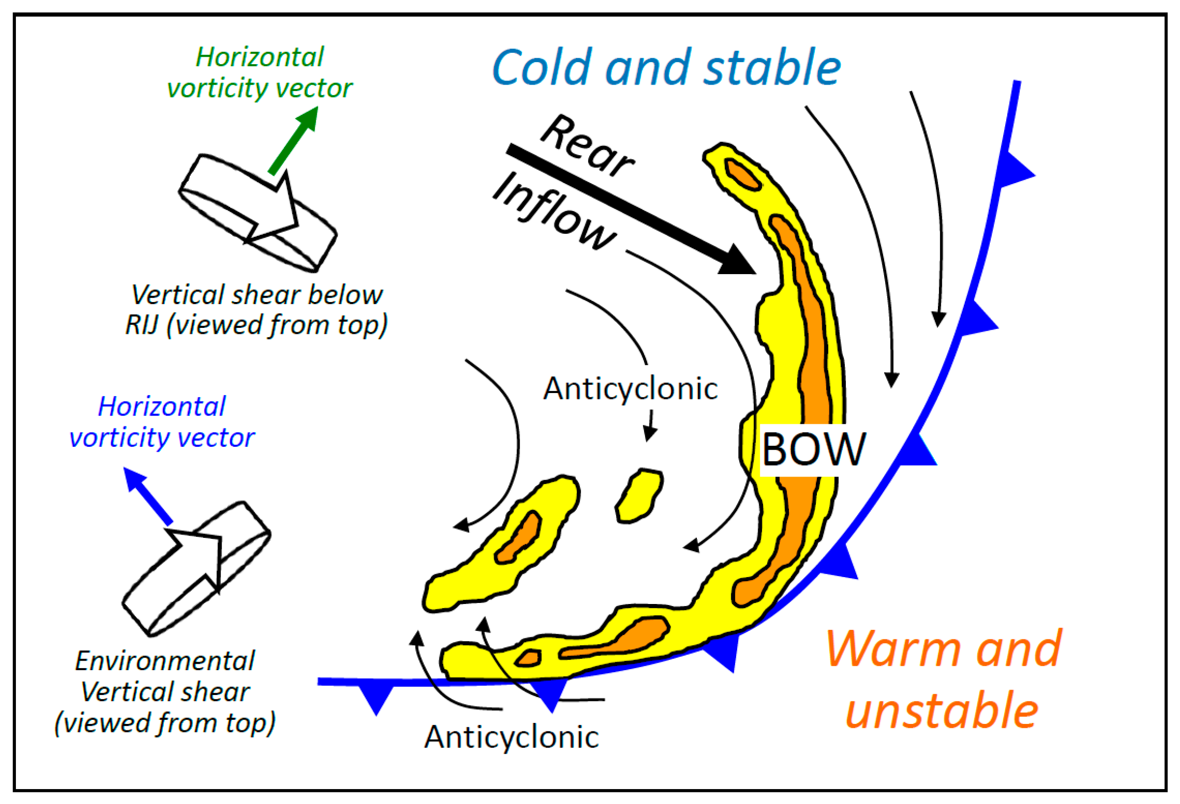
| Symmetric | A pair of cyclonic (northern) and anticyclonic (southern) vortices |
| Location of RIJ | Roughly in the middle of bow line |
| Environmental shear | Westerly shear (RTF): HVVs pointing from right to left of line |
| System-induced vorticity | Between updraft and downdraft: HVVs pointing from left to right |
| Formation mechanism | Tilting of environmental shear by downdraft (early stage), and tilting of system-induced HVVs by updraft (mature stage) |
| Asymmetric (this study) | Only one anticyclonic vortex behind the line |
| Location of RIJ | Near the northern end of bow line |
| Environmental shear (front) | Southwesterly shear: HVVs pointing FTR across the line |
| System-induced vorticity | Below RIJ: HVVs pointing from right to left of line |
| Formation mechanism | Tilting of environmental shear by updraft, tilting of system-induced vorticity by downdraft, stretching, and 3D advection by frontal flow |
Publisher’s Note: MDPI stays neutral with regard to jurisdictional claims in published maps and institutional affiliations. |
© 2022 by the authors. Licensee MDPI, Basel, Switzerland. This article is an open access article distributed under the terms and conditions of the Creative Commons Attribution (CC BY) license (https://creativecommons.org/licenses/by/4.0/).
Share and Cite
Wang, C.-C.; Hou, J.-P.; Tseng, C.-H.; Chang, P.-L.; Lee, D.-I. Study of an Asymmetric and Anticyclonic Bow Echo Near Taiwan. Atmosphere 2022, 13, 331. https://doi.org/10.3390/atmos13020331
Wang C-C, Hou J-P, Tseng C-H, Chang P-L, Lee D-I. Study of an Asymmetric and Anticyclonic Bow Echo Near Taiwan. Atmosphere. 2022; 13(2):331. https://doi.org/10.3390/atmos13020331
Chicago/Turabian StyleWang, Chung-Chieh, Jou-Ping Hou, Chun-Hsiang Tseng, Pao-Liang Chang, and Dong-In Lee. 2022. "Study of an Asymmetric and Anticyclonic Bow Echo Near Taiwan" Atmosphere 13, no. 2: 331. https://doi.org/10.3390/atmos13020331
APA StyleWang, C.-C., Hou, J.-P., Tseng, C.-H., Chang, P.-L., & Lee, D.-I. (2022). Study of an Asymmetric and Anticyclonic Bow Echo Near Taiwan. Atmosphere, 13(2), 331. https://doi.org/10.3390/atmos13020331