Abstract
The problem of serious ash accumulation at the lower part of flat box filter cartridges is an important limitation for the improvement of ash cleaning efficiency in this kind of filter. To solve the above-mentioned problem, the type of slotted blowing hole impacting the performance of the ash removing under the same ash cleaning area was studied. In the present work, a total of four types of slotted blowing holes with different length were designed. The influence of blowing distance and blowing pressure on dust removal performance were investigated. Numerical simulation was conducted to demonstrate the mechanism of the dust removal process. An industrial coating test was also carried out to investigate and verify the actual ash cleaning performance under the optimal conditions as obtained from the above investigations. The results showed that: (1) the performance of dust cleaning produced by a three-slit blowhole was better than that by a four-slit blowhole; (2) 0.2 MPa was determined to be the optimal blowing pressure, which meets the requirement of ash cleaning; (3) 20 mm was selected as the optimal blowing distance, as this was the distance at which the surface side wall pressure at the non-positive-to-blow hole area was obviously increased, indicating that the whole performance of ash cleaning could be improved. The results obtained in this study are of great significance for improving the efficiency of dust removal in the use of flat box filters, promoting the development of dust removal technology, protection of environment, and reduction of human health damage.
1. Introduction
Cartridge dust collectors have been widely used to collect the dust generated from the production process in many fields such as metallurgy, chemical industry, electric power, and machinery because of their significant advantages such as high fold ratio, large filtration area, and high space utilization efficiency [1,2,3]. Generally, the circular filter cartridge is more widely used as its cleaning method and principle are consistent with the bag filter, which can better ensure the cleaning effect in the present stage [4]. The rectangular flat pleated filter, which was proposed in recent years, has attracted more and more attention. The square structure enables the rectangular flat pleated filter to have a greater space utilization efficiency and better operation convenience, especially for the situation of limited space [5,6,7]. However, despite the many advantages of the rectangular cartridge, it has not yet been used on a large scale, such as in China [8,9,10]. This is because its dust removal control is essentially different from that of the circular filter cartridge or filter bag, and its poor dust removal performance is currently the main reason that restricts its wide-range application [11,12]. A reasonable cleaning method and revealing the relationship between various cleaning parameters and cleaning effects are effective means of improving its cleaning performance, which is of great significance to promote its wide-range application, solve the problem of dust cleaning inside the confined space, ensure the occupational health of workers, and protect the environment [13,14].
The rectangular flat pleated filter is currently in the primary application stage, and the research on its cleaning performance is relatively small. In fact, the parameters, such as the structure and size of the blowing hole, are important factors that have an impact on the deashing performance, especially on the uniformity of the deashing [15,16]. Chen comparatively studied the effect of dust discharge and system pressure drop of a flat square filter cartridge in the deashing performance by using slotted and round-holed nozzles, respectively; the experiment proved that the slotted nozzle had a better deashing performance [17]. Zhang et al. studied the relationships between the solenoid valve, opening hole type, blowing distance, blowing pressure, and value distribution of the side wall pressure on the self-built pulse blowing test bench [18]. Kang designed a new type of slotted nozzle for ash removing from the rectangular flat pleated filter and comparatively studied its ash removing performance with that of the round-holed nozzle; the results showed that the slotted nozzle had a better deashing performance, but there is still a problem of uneven distribution of air flow in each injection hole [19]. Li proposed a new kind of deashing method named the colliding pulse jet technique for dust filter cleaning. The results showed that the performance of ash removal by the collision jet without time interval was improved, but there was a problem of high gas consumption [20]. The study by Li et al., using the methods of theoretical calculation, numerical simulation, and industrial coating experiments, demonstrated that: (1) the size of the slot nozzle has an effect on the cleaning effect; (2) 40~60% of dust usually remained located in the upper part of the filter bag which is not directly facing the nozzle hole; and (3) gas-solid concentration and pulse interval have little effect on the cleaning effect. Many achievements have been made, but the systematic disclosure of the relationship between the parameters and the cleaning effect of dust is still lacking, especially for the study of multiple holes on the same spray pipe, which generally adopts the designer’s experience value in the actual industry [21].
One important issue focused on in this work was to demonstrate the mechanism and improve the situation of ash heavily accumulating at the bottom. This problem arose because the upper and lower sections of the rectangular cylinder are fixed, where they are weakened by the shock effect of pulsed back-blowing air, resulting in serious powder trapping at both ends of the cylinder and dust accumulation at the bottom due to the action of gravity. In this work, non-coated and coated powder tests were both carried out. The parameters, including the nozzle number, pulse pressure, jet distance, filtration velocity, dust mass concentration, were investigated to observe the effects on the system resistance, and the residual amount of dust was used to recognize the dust cleaning performance. Then, a numerical simulation was conducted to demonstrate the mechanism of the dust removing process. Last, a continuous industrial test was conducted to confirm the effect of the optimal combined condition of dust cleaning obtained in this study and identify the continuous service life of the rectangular filter cartridge under this combined condition. The objective of this paper is to provide an efficient method for controlling the ash cleaning parameters to obtain a good performance of ash cleaning, promoting the application of the rectangular flat pleated filter.
2. Experimental Section
2.1. Test of Pulse Cleaning on Filter Cartridge without Powder Coating
2.1.1. Experimental Device
The pulse cleaning device used in the experiment is shown in Figure 1. The pulse clean device involved 3 parts, including a gas supply system, blowing system, and pressure test system. The gas supply system was composed of an HAD-1SNF frozen air dryer, WW-0.9/10B-Q-q-type air compressor, and gas storage tank. The blowing system was mainly composed of an SXC-8A1 pulse control instrument, gas bag (volume was 24 L, wall thickness was 7.5 mm), solenoid valve (DMF-ZM-25, 1″), spraying pipe (1200 mm length, 28 mm diameter), and flat-type box filter, which was created by polyester spinning non-woven fabric (B16500, 470 mm length, 64 mm width, 1000 mm height, 31 mm fold depth, 33 single-sided folds, 4.3 m2 filtration area). The pressure test system mainly included fiber sensors, KA-FPP90 pressure sensors, and computers (equipped with OSA software).
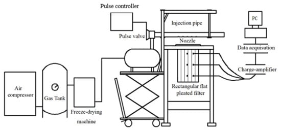
Figure 1.
Pulse cleaning device used in the experiment.
2.1.2. Sampling Point Design and Evaluation Standard
The impacts of the length of the slotted blow hole, blowing distance, and blowing pressure on the dust cleaning performance were investigated. According to our exploration tests and the work by Lu and Tsai, which demonstrated that fly ash can be cleaned from the surface of the filter cartridge when the surface side wall peak pressure exceeded 500 Pa [22], a surface side wall peak pressure of 500 Pa inside the filter cartridge was adopted as the evaluation indicator in the present work to initially determine whether it met the intensity required for deashing from the flat filter cartridge. The pressure value was detected by the pressure sensor. Six pressure monitoring points (P1–P6) were set as shown in Figure 2. These six points were distributed in two distinct areas with a significant distinction between the ash cleaning characteristics: positive-to-blow hole area (P1–P3) and non-positive-to-blow area (P4–P6). The distance of each point to the outlet of the filter cartridge are shown in Figure 3.
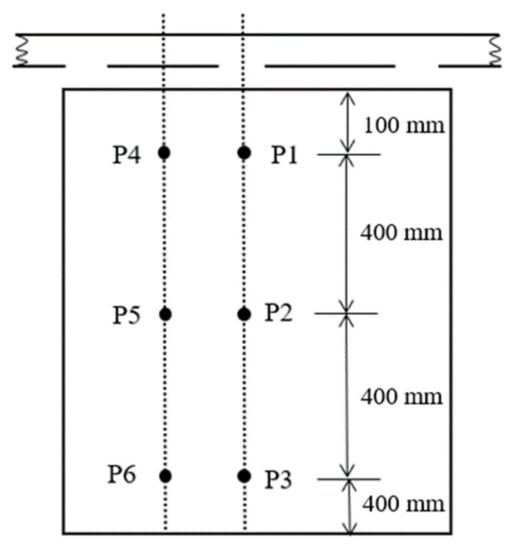
Figure 2.
Setting of the six pressure monitoring points (P1, P2 and P3 locates positive-to-blow hole area; P4, P5 and P6 locates non-positive-to-blow area).
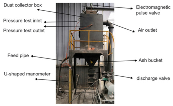
Figure 3.
Vertical flat square cartridge filter.
A total of 4 types of slotted blowing holes with different lengths were designed. The area of each hole was about 398 mm2, calculated based on the design manual of the dust collector. The specific design parameters are shown in Table 1 and Table 2. Each test was repeated 6 times and the average value was used to ensure the accuracy of the test.

Table 1.
Parameters of the slotted blowing hole.
Table 2.
Operation parameters of the tests.
2.1.3. Experimental Procedure and Statistics Collection
For each experiment, the air passed through the air compressor to form compressed air in the compressed gas storage tank and then passed through the freeze-type dryer to obtain clean compressed air, which was stored in the gas bag. The compressed gas was introduced into the spray pipe through the solenoid valve, which was controlled by the pulse control instrument to release the compressed gas. The pulse control instrument was timed to be turned on according to the experimental parameters, and the compressed gas was simultaneously injected at a specific time for dust removal via the blowing holes. Piezoelectric pressure sensors were installed on the inner wall of the flat box filter cartridge according to the settings of the pressure monitoring points, as shown in Figure 2. When the pressure signal was received, the corresponding electrical signal was generated, which passed through the charge amplifier and was then collected and recorded by the data acquisition instrument. The collected electrical signal data were processed and analyzed by the software DasView 2.0 to be converted into pressure data. The conversion formula of electrical signal data and pressure value data is shown in the equation below.
where represents the pressure value in , represents electrical value in , represents the magnification of the charge amplifier in , and represents the transducer sensitivity in .
2.2. Numerical Simulation
According to the actual size parameters of the device, the 1:1 physical model was established by the SolidWorks software. The software of Fluent Meshing was employed to check the quality of the grid. As a result, a total grid of more than 3 million units was obtained and the maximum external obliqueness of the grid was 0.66, indicating that the grid quality was good and that the simulation calculation requirements could be met. The blowing inlet was set at the mouth of the blowing pipe. A pressure inlet was employed, and its pressure value was set as 0.3 MPa. The wall surface of the outer basin was set as an airflow exit, and a pressure outlet was used. The boundary conditions of the blowing tube wall, nozzle wall, and box body were set as avoid slipping (wall). The boundary conditions of the airflow inlet of the seam blowing pipe and the upper part of the flat-type square filter were set as the interior structure. The boundary condition of the filter material was set as porous jump medium (Porous JUMP) with a thickness of 0.8 mm and a penetration rate of 5E-11. The operating pressure was set to 0 Pa.
2.3. Industrial Coating Tests
2.3.1. Experimental Device and Experimental Parameters
The test system consisted of a dusty feeder, vibrating feeding machine, dust collector box, jet pipe, solenoidal valve, reference fan, and U-shaped tube, as shown in Figure 3.
Flour ash with a particle size of 9.180–247.347 μm and D50 = 49.473 μm was adopted. The U-shaped tube connected the entrance and exit of the dust collector to test the operation resistance of the dust removal system. The ash was cleaned timely online, and the specific operating conditions are shown in Table 3.
Table 3.
Operating conditions of the industrial coating tests.
2.3.2. Experimental Procedure
For each test, the dust concentration was kept unchanged and we changed the filter wind speed, recording the reading of the U-shaped pipe every 10 min, that is, the drilling system running resistance. After 60 min of run time, we turned off the pulse controller and pressure valve and took out the filter tube for weighing. The remaining amount of the dust could be obtained by the change in the filter cartridge’s weight before and after operation. The difference of the system running resistance could be obtained by the system resistance before and after operation.
3. Results and Discussion
3.1. Impact of Blowing Distance on Peak Pressure of Flat-Type Box Filter
The influence of the slotted blow hole length under different blowing distances at 0.3 MPa of blow pressure is shown in Figure 4.
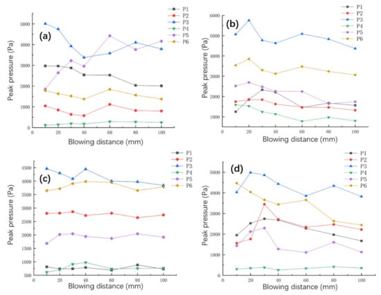
Figure 4.
Influence of blowing distance and length of slotted blow hole under blow pressure 0.3 MPa on peak pressure: (a) two slotted blow holes, (b) three slotted blow holes, (c) four slotted blow holes, and (d) five slotted blow holes.
For the scenario of two slotted blow holes as shown in Figure 4a, two conclusions can be made: (1) the peak pressures at P1, P2, P3, and P6 first increased and then decreased with as the blowing distance increased; and (2) the peak pressures located at the positive-to-blow hole area (P1–P3) were larger than that at non-positive-to-blow hole area (P4–P6). Specifically, although P4 and P5 were both located at the non-positive-to-blow hole area, their peak pressures change differently with the increase in the blowing distance. The increase in the blowing distance has a negligible impact on the peak pressure at P4, whereas it has an obvious impact on the peak pressure at P5. This is because after the airflow enters the flat filter cartridge and rapidly spreads, inducing more gas to enter the middle of the filter cartridge; when located at the area facing the non-positive-to-blowing hole, the pressure of the filter cartridge is increased. When the blowing distance was less than 20 mm, the peak pressure at point P4 was the smallest. This is because when the blowing distance is too small, the airflow of the blowing hole is not covered to the upper part that directly faces the non-positive-to-blowing hole. When the blowing distance was 40 mm, the peak pressure of each measuring point was the smallest. When the blowing distance was greater than 60 mm, the peak pressure of each measuring point began to decrease (except at P3 whose peak pressure decreased when the blowing distance was greater than 80 mm). This is because when the blowing distance is too large, more blowing airflows are scattered outside the flat filter cartridge during the diffusion process, reducing the air flow that enters the cartridge. At the same time, there was also a phenomenon that the peak pressure was always less than 500 Pa under any blowing distance investigated in the present work, indicating that two slotted blow holes were not suitable for dust cleaning in the present cartridge.
For the scenario of three slotted blow holes as shown in Figure 4b, as the blowing distance increased, the peak pressures of the points positive-to-blowing hole first increased and then decreased. At the same time, when the blowing distance was 20–30 mm, the peak pressure of each measurement point reached their highest values. When the blowing distance was 40 and 60 mm, the peak pressure at P4 did not meet the requirement of the dust cleaning intensity, whereas the remaining points met the requirement.
For the scenario of four slotted blow holes as shown in Figure 4c, as the blowing distance increased, the peak pressure of each measuring point did not change much. This shows that the diffusion and superposition of the airflow entering the filter cartridge was not strong and it may also be superimposed to the position where the measurement point was not covered. When the blowing distance was 20–40 mm, the peak pressure of each measuring point reached their highest values. The pressure of each measuring point met the requirements of the ash cleaning strength.
For the scenario of five slotted blow holes as shown in Figure 4d, when the blowing distance increased, the peak of the pressure of each measuring point first increased and then decreased, and the maximum values were reached when the blowing distance was 20–30 mm. At the same time, the peak of the side wall pressure at the measuring point P4 was always less than 500 Pa, which indicates that it was difficult to meet the requirements of the ash cleaning intensity under any of the above blowing distances.
From Figure 4a–d, it can be concluded that the conditions of two and five slotted blow holes are not suitable for dust cleaning for the present cartridge, as in these cases the peak pressure at P4 always cannot meet the requirement of dust cleaning intensity under any blowing distance investigated in the present work. The peak pressure of the measuring point on the cartridge investigated by the four slotted blow holes is negligibly affected by the blowing distance.
Table 4 shows the analysis of the average surface side wall peak pressure under different types of blowing holes with different blowing distances. It can be seen that the average surface side wall peak pressure first increased and then decreased with the increase in blowing distance. Combined with the analysis of Figure 4 and Table 4, under the condition that the dust cleaning intensity requirement of the filter cartridge is met, when the spray distance is 10–60 mm, the average surface side wall peak pressure produced by three slotted blowing holes was always greater than that produced by four slotted blowing holes at the same blowing distance. The best operating conditions can be determined preliminarily: three slotted blowing holes and 20 mm of blowing distance.
Table 4.
Analysis of the average surface side wall peak pressure under different type of blowing hole with different blowing distances.
3.2. Impact of Blowing Pressure on Peak Pressure of Flat-Type Box Filter
Increasing the blowing pressure is the most effective means to improve the dust cleaning performance of a flat filter cartridge. The demonstration of the influence of blowing pressure on the peak pressure of the cartridge is important to better control the dust cleaning performance. Figure 5 shows the influence of slotted blow hole length under different blow hole numbers at a 20 mm blowing distance.
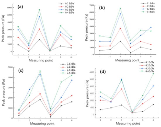
Figure 5.
Influence of blowing pressure and length of slotted blow hole under a blowing distance of 20 mm on peak pressure: (a) two slotted blow holes, (b) three slotted blow holes, (c) four slotted blow holes, and (d) five slotted blow holes.
Figure 5 shows that the increase in the blowing pressure increases the peak pressure at all measuring points. Furthermore, the increase in the blowing pressure obviously increases the peak pressures at the measuring points located at the positive-to-blow hole area, while the increase in the blowing pressure has a small increasing effect on the peak pressure at the measuring points at the non-positive-to-blow hole area. Therefore, lower blowing pressure leads to a better effect on the uniformity of the dust cleaning performance, once the requirements of the ash cleaning intensity are met.
Table 5 shows the average surface side wall peak pressure (AP) and minimum surface side wall peak pressure (MinP) by different types of blowing holes with different blowing pressures when the blowing distance was set at 20 mm. The AP and MinP increased with the increase in the blowing pressure, but the increasing rate declined at all measuring points and each type of blowing hole. At the same blowing pressure, the AP first increased and then decreased, while the MinP first decreased and then increased with the increase of the number of the blowing holes. For five slotted blow holes, although AP can meet the pressure requirement of dust cleaning, the MinP was less than 500 Pa when blowing pressure was at 0.1–0.4 MPa, indicating that five slotted blow holes is not a good choice for dust cleaning in the present cartridge. It can also be observed that under the premise that the blowing pressure is unchanged, the type of three slotted blowing holes is better than the four slotted blowing holes for improving the deashing performance. Specifically, at 0.2 MPa, both the APs and MinPs produced by the three slotted blowing holes were larger than that by the four slotted blowing holes, and the MinP produced by the four slotted blowing holes was less than 500 Pa, which does not meet the requirement of dust cleaning. Three slotted blowing holes can meet the requirements of a good dust cleaning performance under 0.2 MPa, and the problem of serious ash accumulation at the lower part of the flat box filter cartridge can be solved.
Table 5.
Average surface side wall peak pressure (AP) and minimum surface side wall peak pressure (MinP) under different types of blowing holes with different blowing pressures (blowing distance of 20 mm).
3.3. Static Pressure Distributed Cloud Map
Figure 6 shows the static pressure distributed cloud map under the conditions of three slotted blowing holes at different time. It can be seen that the diffusion and induction of airflow simultaneously exist when the airflow was entering the cartridge. Figure 6b and c obviously demonstrate that the blowing air flow entering the cartridge can distribute relatively uniform via diffusion and induction. Meanwhile, a difficult and key problem for ash cleaning could also be clearly demonstrated from the simulation results: the upper and lower parts of the flat box cartridge filter have larger surface wall pressures, which can avoid the problem of ash accumulation. The above results are in accordance with the experimental results of the former part.
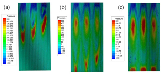
Figure 6.
Static pressure distributed cloud map under the condition of three slotted blowing holes at (a) 0.01 s, (b) 0.02 s, and (c) 0.03 s.
3.4. Ash Cleaning Performance of Industrial Coating Test
The influence of the gas-solid concentration and filtration velocity on the system resistance of the flat box cartridge filter under the condition of a 0.2 MPa blowing pressure and three slotted blowing holes are shown in Table 6.
Table 6.
Influence of gas-solid concentration and filtration velocity on the system resistance of the flat box cartridge filter (blowing pressure of 0.2 MPa, three slotted blowing holes).
Table 6 shows that the system resistances of the flat box cartridge filter were not large (lower than 206 Pa) under all gas-solid concentrations and filtration velocities investigated, which can ensure the stable operation of the system. With the increase in the gas-solid concentration of dust, the running resistance gradually increased, and the amount of powder on the surface of the filter cylinder also gradually increased. With the filtration velocity gradually increasing, the operation resistance and dust residual amount change little, indicating that the gas-solid concentration of dust is the main factor affecting the operation resistance of the system. When the filter wind speed was 1.0 m/s, the amount of dust on the filter cylinder surface first decreased and then increased. Under the condition of a gas-solid concentration of 0.2 kg/m3, the residual amount of dust was at least 0.72 kg, and the effect of dust removal was good.
4. Conclusions
In this work, the impact factor, regulation, and performance of dust cleaning from flat box cartridge filters were studied. Dust cleaning experiments without dust coating, observing dust cleaning mechanisms by simulation, and industrial coating tests were carried out. Four conclusions could be stated:
(1) The peak pressure of the pulse air flow formed by the two-slit blowhole (2 × 99 mm) and five-slit blowhole (5 × 40 mm) in the upper part of the filter cylinder that is not directly against the blowhole cannot reach the pressure requirement of ash removal. The performance of dust cleaning produced by the three-slit blowhole (3 × 66 mm) is better than that of the four-slit blowhole (4 × 50 mm) from the aspect of raising the peak pressure of the non-positive-to blow area, and its optimal blowing distance is 20 mm.
(2) Higher blowing pressure can result in higher average surface side wall peak pressure. However, the higher peak pressure also results in more energy consumption and more serious wear and tear of filter materials. The optimal blowing pressure was determined as 0.2 MPa.
(3) Under the optimal condition of a 0.2 MPa blowing pressure, 20 mm blowing distance, and three-slit blowhole, the results from the industrial coating tests show that the system runs stably, the running resistance is relatively low, and the dust removing performance is good. At the same time, the problem of serious ash accumulation at the lower part of the flat box filter cartridge is also avoided.
(4) By comparing the existing relevant studies, the structure and size of the three-slit blowhole proposed in this study can induce more compressed gas to participate in the deashing process, obtaining greater cleaning strength and further improving the cleaning efficiency. For example, the results of the study carried out by Cheng [17] showed that under the conditions of a blowing distance of 20 mm and blowing pressure of 0.3 MPa, the average surface side wall peak pressures inside the flat box cartridge filter were 1102 and 1654 Pa, which were caused by one-slit blowholes with sizes of 1 × 39 and 3 × 13 mm, respectively; these values are far less than that of the 2921 Pa obtained in our study under the same conditions.
The findings of this work can provide foundational data and technical support for the improvement of ash cleaning in flat box cartridge filters to reduce environmental pollution and human health damage.
Author Contributions
Conceptualization, X.L. and H.C.; methodology, X.L. and J.L.; software, Y.X.; validation, X.L. and J.L.; formal analysis, X.L.; investigation, X.L. and Y.X.; resources, H.C. and Z.X.; data curation, X.L. and J.W.; writing—original draft preparation, X.L.; writing—review and editing, J.W. and X.L.; visualization, X.L. and J.W.; supervision, H.C.; project administration, X.L. All authors have read and agreed to the published version of the manuscript.
Funding
This research received no external funding.
Institutional Review Board Statement
Not applicable.
Informed Consent Statement
Not applicable.
Data Availability Statement
Not applicable.
Conflicts of Interest
The authors declare no competing financial interest.
References
- Saleh, A.; Tafreshi, H.V.; Pourdeyhimi, B. Service life of circular pleated filters vs. that of their flat counterpart. Sep. Purif. Technol. 2015, 156, 881–888. [Google Scholar] [CrossRef]
- Qian, Y.; Chen, H.; Dai, H.; Liu, T.; Kuang, T.; Bian, L. Experimental study of the nozzle settings on blow tube in a pulse-jet cartridge filter. Sep. Purif. Technol. 2018, 191, 244–249. [Google Scholar] [CrossRef]
- Zhang, M.; Chen, H.; Yan, C.; Li, Q.; Qiu, J. Investigation to rectangular flat pleated filter for collecting corn straw particles during pulse cleaning. Adv. Powder Technol. 2018, 29, 1787–1794. [Google Scholar] [CrossRef]
- Li, J.; Wu, D.; Wu, Q.; Luo, M.; Li, J. Design and performance evaluation of novel colliding pulse jet for dust filter cleaning. Sep. Purif. Technol. 2019, 213, 101–113. [Google Scholar] [CrossRef]
- Chen, S.; Chen, D.-R. Numerical Study of Reverse Multi-Pulsing Jet Cleaning for Pleated Cartridge Filters. Aerosol Air Qual. Res. 2016, 16, 1991–2002. [Google Scholar] [CrossRef]
- Shim, J.; Joe, Y.-H.; Park, H.-S. Influence of air injection nozzles on filter cleaning performance of pulse-jet bag filter. Powder Technol. 2017, 322, 250–257. [Google Scholar] [CrossRef]
- Kim, J.U.; Hwang, J.; Choi, H.J.; Lee, M.H. Effective filtration area of a pleated filter bag in a pulse-jet bag house. Powder Technol. 2017, 311, 522–527. [Google Scholar] [CrossRef]
- Kang, F.; Cheng, H.; Leng, H.; Zen, S.; Xu, Z.; Li, X.; Lǖ, J.; Lin, L.; Chen, H. Performance optimization of rectangular flat pleated filter with slit nozzle for dust cleaning. Powder Technol. 2020, 376, 320–331. [Google Scholar] [CrossRef]
- Lin, L.; Liu, T.; Yuan, N.; Xu, Z.; Chen, H. Study on the influence of venturi on the cleaning performance of elliptical filter cartridge. Powder Technol. 2021, 377, 139–148. [Google Scholar] [CrossRef]
- Yuan, N.; Ren, L.; Wang, B.; Teng, D.; Li, P.; Xu, Z.; Li, Y.; Chen, H.; Lin, L. Experimental study on the effects of diversion device on pulse-jet cleaning of horizontal filter cartridge. Process Saf. Environ. Prot. 2021, 145, 247–254. [Google Scholar] [CrossRef]
- Andersen, B.O.; Nielsen, N.F.; Walther, J.H. Numerical and experimental study of pulse-jet cleaning in fabric filters. Powder Technol. 2016, 291, 284–298. [Google Scholar] [CrossRef]
- Huang, M.; Yan, C.; He, C.; Tang, C.; Yang, F.; Li, P. The relationship between peak pressure and parameters of pulse-jet cleaning in a sintered plastic filter. J. Air Waste Manag. Assoc. 2021, 71, 1055–1066. [Google Scholar] [CrossRef]
- Li, S.; Xin, J.; Xie, B.; Jin, H.; Hu, S.; Song, S.; Zhou, S.; Zhou, F. Experimental investigation of the optimization of nozzles under an injection pipe in a pulse-jet cartridge filter. Powder Technol. 2019, 345, 363–369. [Google Scholar] [CrossRef]
- Kim, J.S.; Lee, M.-H. Measurement of effective filtration area of pleated bag filter for pulse-jet cleaning. Powder Technol. 2019, 343, 662–670. [Google Scholar] [CrossRef]
- Kang, F.F.; Lin, L.Y.; Zeng, S.M.; Li, T.H.; Cheng, H.; Li, T.H.; Chen, H.Y. Optimization of cleaning performance of flat filter under multi pulse-jet. China Powder Sci. Technol. 2020, 26, 55–62. (In Chinese) [Google Scholar]
- Zhang, M.X.; Li, Q.Q.; Li, X.; Yan, W.; Fu, G.; Juan, L.; Chen, H. Dust-cleaning experiment of pulse-jet flat filter cartridge. Chin. J. Environ. Eng. 2017, 11, 2377–2383. (In Chinese) [Google Scholar]
- Cheng, H. Optimization Study of the Pulse-Jet Slot-Type Nozzle. Master’s Dissertation, Southwest University of Science and Technology, Mianyang, China, 2022. (In Chinese). [Google Scholar]
- Zhang, Q.; Liu, D.; Wang, M.; Shu, Y.; Xu, H.; Chen, H. Characteristics and evaluation index of pulse-jet dust cleaning of filter cartridge. Process Saf. Environ. Prot. 2021, 157, 362–374. [Google Scholar] [CrossRef]
- Kang, F.F. Performance Optimization of Rectangular Flat Pleated filter For Dust Cleaning of Pulse-Jet Cartridge Filter. Master’s Dissertation, Southwest University of Science and Technology, Mianyang, China, 2020. (In Chinese). [Google Scholar]
- Li, Q.Q. Study on Cleaning Performance of Flat Filter Cartridge during Pulse Cleaning. Master’s Dissertation, Southwest University of Science and Technology, Mianyang, China, 2013. (In Chinese). [Google Scholar]
- Li, Q.; Zhang, M.; Qian, Y.; Geng, F.; Song, J.; Chen, H. The relationship between peak pressure and residual dust of a pulse-jet cartridge filter. Powder Technol. 2015, 283, 302–307. [Google Scholar] [CrossRef]
- Lu, H.C.; Tsai, C.J. A pilot-scale study of the design and operation parameters of a pulse-jet baghouse. Aerosol Sci. Technol. 1998, 29, 510–524. [Google Scholar] [CrossRef]
Publisher’s Note: MDPI stays neutral with regard to jurisdictional claims in published maps and institutional affiliations. |
© 2022 by the authors. Licensee MDPI, Basel, Switzerland. This article is an open access article distributed under the terms and conditions of the Creative Commons Attribution (CC BY) license (https://creativecommons.org/licenses/by/4.0/).