Article

Multi-Hazard Assessment of a Flood Protection Levee

1
Modelling in Civil Engineering and Environment, National Engineering School of Gabes, University of Gabes, Gabes 6029, Tunisia
2
Institute for Radiological Protection and Nuclear Safety (IRSN), 92260 Fontenay-aux-Roses, France
*
Author to whom correspondence should be addressed.
Atmosphere 2022, 13(10), 1741; https://doi.org/10.3390/atmos13101741
Submission received: 30 September 2022 / Revised: 15 October 2022 / Accepted: 18 October 2022 / Published: 21 October 2022
(This article belongs to the Special Issue Multi-Hazard Risk Assessment)

Abstract

:
Earthquake-induced liquefaction is one of the main causes of levee breaches that can threaten human life and property. Conventionally, liquefaction hazard has been assessed in terms of the factor of safety F o S against liquefaction which ignores the potential variability of groundwater table (GWT) due to precipitation events. A probabilistic methodology, taking into account these GWT variations over time, is therefore presented in this study to assess the liquefaction hazard of an earthen flood protection levee. A frequency analysis based on the Annual Maxima/Generalised Extreme Value (AM/GEV) approach is first used to characterize the distribution of GWT extreme values. The CPT-based method is then applied with the provided GWT scenarios to predict liquefaction and display the hazard curves. Assuming a single constant GWT estimate during an earthquake revealed a certain liquefaction hazard within a sandy layer. Considering GWT variations during earthquakes showed, however, that liquefaction is unlikely to occur with an F o S threshold set at 1.0. These findings highlight: (1) the conservatism of the conventional approach that overestimates the liquefaction hazard, (2) the importance of the proposed probabilistic approach as a complementary tool for more reliable decision-making, and (3) the dependency of liquefaction hazard predictions on the degree of uncertainty in GWT estimates and F o S threshold.

1. Introduction

Flood protection levees are important engineering systems for handling water resources and protecting urban areas from flooding and associated damages [1,2,3]. Nearly 100,000 miles of levees have been constructed in the USA to protect homes, businesses and farmland from flooding events. France has also built over 5000 miles of levees along its rivers and coastlines for the same purpose.
A majority of these levees are ancient earthen systems that were built in a haphazard manner using the rivers’ own deposits with a lack of adequate soil compaction process and/or internal drainage systems [4]. This makes them relatively fragile structures [5], and being continually exposed to multiple hazards during their lifetime can easily lead to their breaches. A failure at one specific location of an earthen levee or one of its components can cause a catastrophic failure of the entire protection system, leading to monumental repercussions, sometimes with dramatic and unanticipated consequences on human life, property and the country’s economy [6,7]. For instance, during Hurricane Katrina in 2005, catastrophic levee failures led to devastating flooding in New Orleans (USA) city with more than 1500 deaths due directly to the surge of floodwater within the greater New Orleans region [8].
In earthquake-prone areas, one of the main initial causes of levee systems breaches is soil liquefaction, as evidenced by Sasaki et al. [9] based on damage investigation for river levees after the 2011 Tohoku earthquake in Japan. Earthquake-induced liquefaction is a disastrous phenomenon that commonly occurs in saturated soils when the build-up of pore water pressure due to a strong ground shaking during an earthquake reduces the effective stress, causing the soil to lose shear strength and stiffness and then behave as a fluid [7,10].
Earthquake-induced liquefaction hazard has conventionally been assessed in terms of the factor of safety F o S against liquefaction using the simplified CPT- and SPT-based procedures [11,12,13,14,15,16]. These methods rely on F o S evaluation which involves separate calculations of the cyclic resistance ratio (CRR) and cyclic stress ratio (CSR) due to seismic shaking. This requires the GWT to be estimated during subsurface exploration and design earthquakes for CRR and CSR evaluations, respectively. However, GWT values often measured in geotechnical borings and/or monitoring wells are usually uncertain and unreliable, with significant spatial and temporal variability due to various factors, such as hydraulic soils’ properties and precipitation events. Assigning single constant values to GWT can, therefore, easily lead to erroneous or doubtful assessments of liquefaction hazard [17]. Although being recognized both spatially and temporally, GWT variability is not or rarely considered part of the design process and/or risk assessment of geotechnical structures [18]. For instance, to the best of the authors’ knowledge, no previous study has assessed the liquefaction hazard of earthen levees with consideration of GWT variability over time. Tyagunov et al. [19] have presented a methodology for multi-hazard fragility analysis of fluvial dikes in earthquake- and flood-prone areas considering only the spatial variability of materials properties along the river while a conservative assumption of horizontal phreatic line within the dike core has been made. Recently, the potential influences of GWT estimates in soil liquefaction analysis have been investigated by Chang et al. [20], where it has been shown that both one-groundwater-table (OGT) scenario assumption and misassignment of GWT during subsurface exploration can lead to erroneous liquefaction potential predictions. Some previous studies have suggested as well using both high and low GWT levels for more reliable liquefaction hazard evaluation [21,22].
In this context, a probabilistic methodology is developed in this study to take into account GWT variations over time in earthquake-induced liquefaction assessment of an earthen flood protection levee. The Annual Maxima/Generalized Extreme Value (AM/GEV) approach is therefore conducted through a frequency analysis to characterize the distribution of GWT extreme values available over a time period of 22 years. The simplified conventional CPT-based procedure is then applied to the probabilistic GWT scenarios for different return periods to provide estimates of the levee liquefaction probability, P L , and display the hazard curves.

2. Data and Methods

2.1. Case Study Presentation

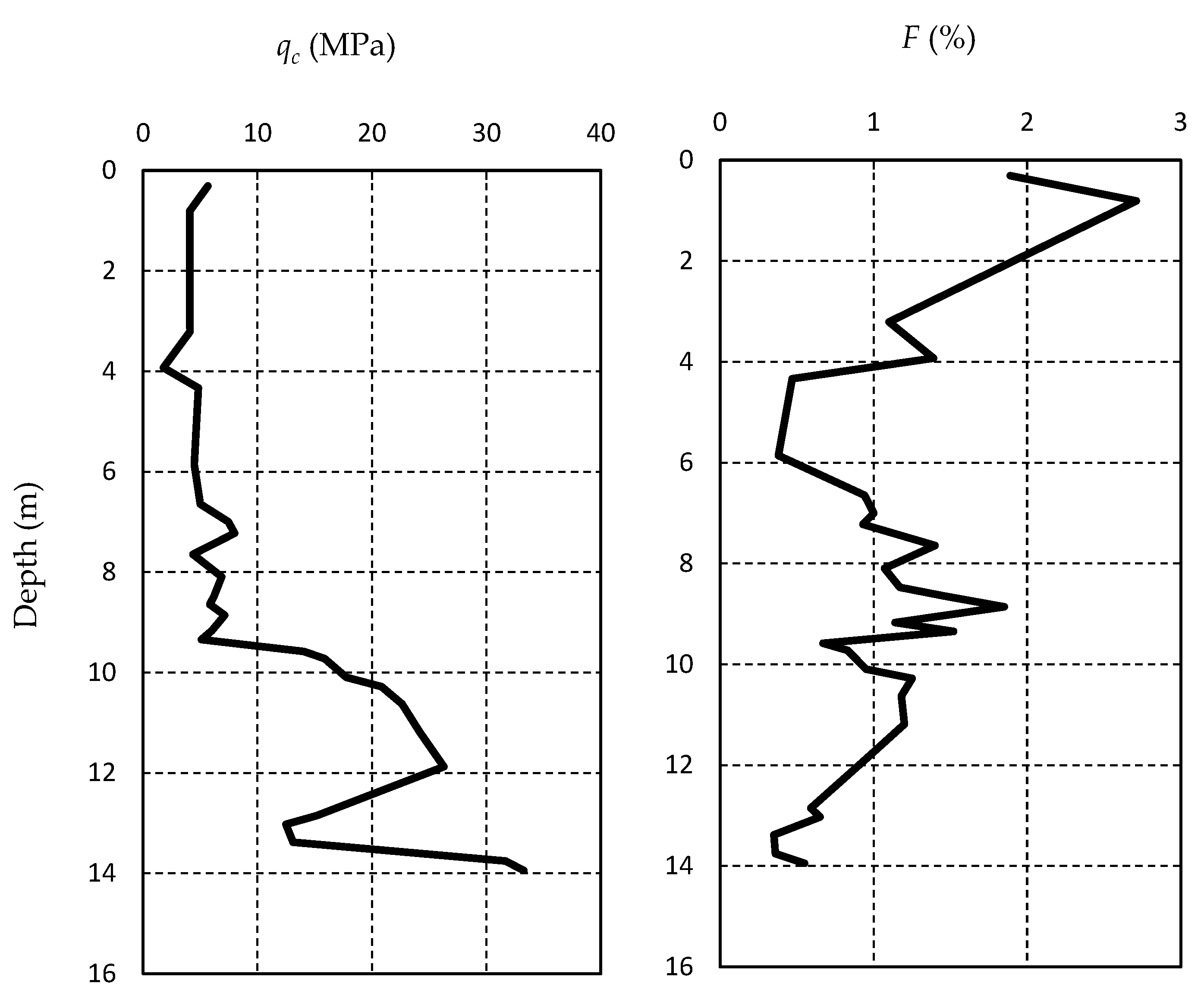
An old earthen levee along a water canal has been considered in this study. The levee is about 150 m in length and 14 m in height, with upstream and downstream slopes equal to 1:3 and 1:5, respectively. The external and internal geometries are depicted in Figure 1. Geological and geotechnical investigations involved geophysical surveys carried out along profiles designed alongside and perpendicularly to the levee and in-situ CPT tests conducted on both levee crest and toe. As an illustration, Figure 2 displays the results of a CPT test performed on the levee crest, where variations of both tip resistance q c and normalized friction ratio F according to depth are represented. Using the existing correlation between soil type and CPT data, in accordance with Robertson et al. [23], highlights the presence of sandy soil at about 10–12 m depth below the crest level resting on a gravelly sand layer.
In addition to the mechanical characterization, collected CPT data were used to evaluate the susceptibility of levee materials to liquefaction. Laboratory tests were also performed on collected samples to determine the physical and mechanical properties of levee materials and characterize their cyclic strengths through cyclic triaxial testing. Investigations results showed that the existing levee is composed of 10 m backfill (soil 1) overlaying a thin 1 m sandy layer (soil 2) and several meters of consolidated marl (soil 3), which constitutes the soft rock substratum without liquefiable layers. Some of the properties values provided for these layers (soil 1 to 3) are summarized in Table 1.
Several piezometers positioned along the whole levee showed that the highest and lowest GWT levels were at 7.3 m and 9.5 m below the crest level over a time period of 22 years from 1996 to 2018.
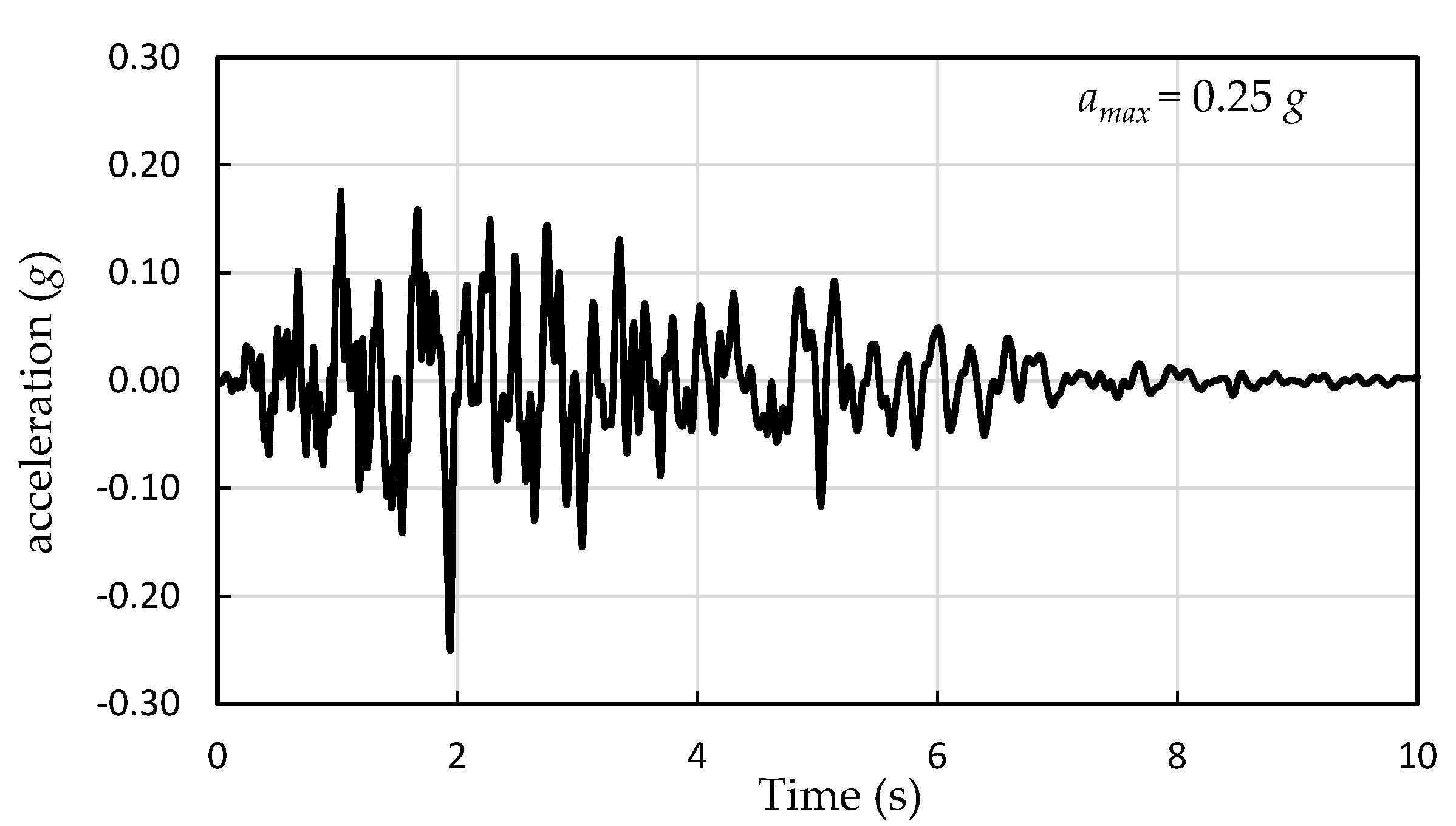
Since no near-field seismic ground motion data were available for the considered site so far, a fictional earthquake with a magnitude M w   and peak horizontal ground acceleration a m a x   set at 5.3 and 0.25   g , respectively, was simulated for liquefaction hazard assessment. Figure 3 shows the acceleration time history of the hypothetical earthquake applied to the levee. It is noteworthy to mention that both M w and a m a x values were deliberately chosen to be both consistent with the seismicity of the study area and significant enough to highlight the liquefaction triggering within the sandy layer in order to compare the obtained results with sufficient reliability.

2.2. Liquefaction Hazard Potential

Seed and Idriss [11] proposed the first simplified procedure to evaluate F o S at a particular depth, which is defined as the ratio of a soil’s capacity to resist liquefaction to the seismic demand imposed upon it. The capacity of soils to resist liquefaction is referred to as the cyclic resistance ratio ( C R R ), which can be calculated using several in-situ tests. such as the standard penetration test (SPT), cone penetration test (CPT) and shear wave velocity ( V s ) test [12]. CPT geotechnical test data are used in this study to evaluate C R R according to the method proposed by Robertson and Wride [24]. On the other hand, seismic demand is referred to as the cyclic stress ratio ( C S R ), which is estimated herein using the following expression:
C S R = 0.65 · a m a x g · σ v 0 / σ v 0 · r d
The factor 0.65 is a weighting coefficient to calculate the equivalent uniform stress cycles required to generate the same pore water pressure during an earthquake; amax is the peak horizontal ground acceleration; g is the acceleration due to gravity (9.81 m/s2); σv0 and σv0′ are the initial total and effective overburden stresses, respectively, at a given depth below the ground surface; and rd is the depth-dependent stress reduction factor that accounts for the dynamic response of the soil column and represents the variation of shear stress amplitude with depth. The stress reduction factor rd at a depth z (in m) is calculated herein using the Liao et al. equation [25].
For an earthquake of magnitude, M w , the F o S is therefore defined as:
F o S = C R R M w = 7.5 C S R · M S F
where M S F is the magnitude scaling factor that accounts for the duration effect of ground motions and adjusts the equivalent uniform shear stress induced by an earthquake of magnitude M w to an equivalent C S R for an earthquake of magnitude M w = 7.5 . Many expressions have been proposed in the literature for M S F evaluation. The recommended expressions of M S F in engineering practice for an earthquake of magnitude M w < 7.5 are [11]:
M S F m i n = 10 2.24 / M w 2.56   and   M S F m a x = M w / 7.5 3.3
In this study, only the lower limit ( M S F m i n ) will be used-- taking a conservative approach-- and will be simply labeled as M S F .
Since both C S R and C R R vary with depth, the liquefaction potential is therefore evaluated at given depths within the soil profile. Soil with F o S < 1 is generally considered liquefiable, while soil with F o S > 1.0 is classified as non-liquefiable. A F o S of 1.25 at a particular depth is recommended by the European earthquake design code (Eurocode 8) as a threshold value for a layer to be categorized as non-liquefiable. Seed and Idriss [26] considered the soil layer with only F o S values between 1.25 and 1.5 as non-liquefiable.

2.3. Frequency Analysis

The Weibull plotting position formula p e = m / N + 1 , where m is the rank order of the ordered magnitudes and N is the record length, is commonly used to calculate the empirical probability of an event. It was shown that this formula predicts much shorter return periods of extreme events than the other commonly used methods [27] and was then used in the present work.
Among many statistical distributions frequently used for extremes, the Generalized Extreme Value GEV function was retained for the annual maxima (AM) sampling method. The GEV distribution introduced by Jenkinson [28] is the limiting distribution for the maximum (and the minimum) of independent identically distributed (iid) random variables. It combines three asymptotic extreme value distributions, identified by Fisher and Tippet [29], into a single form with the following cumulative distribution function:
F x = e 1   +   ξ x μ σ 1 ξ         ξ 0 e   e   x μ / σ                           ξ = 0
where μ , σ > 0 and ξ are the location, scale and shape parameters, respectively. Depending on the value of the shape parameter ξ , the GEV can take the form of the Gumbel, Fréchet or Negative Weibull distributions. When ξ = 0 , it is the type I GEV (Gumbel) distribution, which has an exponential tail. When ξ > 0 , the GEV becomes the Type II (Fréchet) distribution. In the third case, when ξ < 0 , it is the Type III GEV (the reverse Weibull function). The last case has a finite and short theoretical upper tail that may be useful for estimates of specific cases of extreme values, such as surges, which may have an upper bound. The heavy upper tail in the first case with the Fréchet distribution is unbounded and allows for the relatively high probability of extreme values.

3. Results and Discussion

Past investigations along this earthen levee highlighted a liquefaction potential of the sandy layer (soil 2) when subjected to ground shaking. Indeed, this soil located below the piezometric level (i.e., total saturation with a degree of saturation S r = 100 % ) is cohesionless with a median grain diameter   D 50 between 0.05 to 1.5 mm (i.e., in the range of grain size of liquefiable soils according to Iai et al. [30]). In addition, the low permeability ( 10 5   m / s ) of the soil 2 layer and its low compactness are propitious conditions to trigger liquefaction under an earthquake hazard. This first qualitative estimation is followed by a second quantitative evaluation of earthquake-induced liquefaction potential through calculations of   F o S .

3.1. Conventional Liquefaction Hazard Assessment

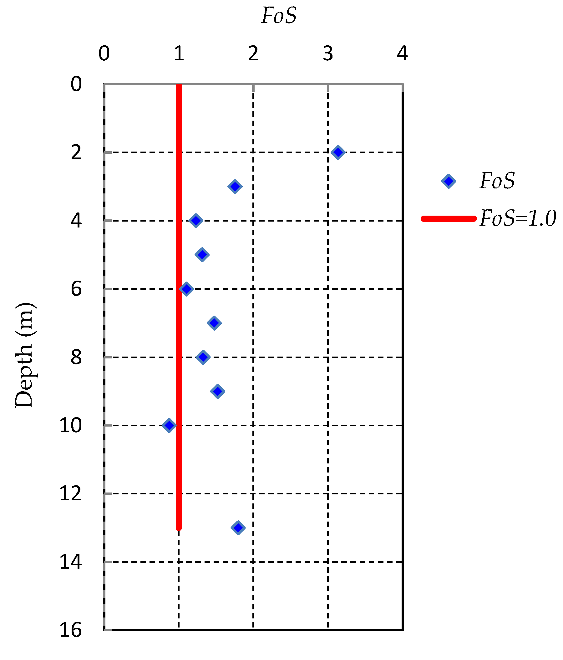
A constant GWT value is first assumed for C S R evaluation. During an earthquake, this GWT is supposed to coincide with the water canal level (i.e., at 2 m depth below the crest level), which represents the worst case for liquefaction hazard within the whole saturated levee. The GWT during subsurface exploration is, however, estimated at 8 m depth below the crest level based on field measurements. The F o S is then calculated for each meter within the levee. Within the middle soil 2 layer, this depth interval is decreased to 0.5 m to better detect its liquefaction potential.
Detailed calculations of C R R and C S R are summarized in Table 2 and Table 3, respectively. Figure 4 shows the obtained F o S according to depth. As it can be noticed, a F o S value less than 1.0 is obtained at 10 m depth below the crest level. This highlights a liquefaction potential at the top of soil 2, confirming the qualitative liquefaction susceptibility of this sandy layer. Greater F o S values are, however, obtained for soil 1 and soil 3. In most cases, the F o S exceeds the threshold value ( F o S = 1.25 ) suggested by Eurocode 8, therefore categorizing both soil 1 and soil 3 as non-liquefiable. These results were validated through cyclic triaxial tests for soil 1 and soil 3, while the samples’ number was insufficient to draw accurate results for soil 2. A staged non-linear dynamic analysis of the levee was therefore developed using SEEP/W and Quake/W (GeoStudio 2021). The dynamic analysis provided results highlighting a liquefaction potential for almost the whole layer of soil 2 and confirming hence the conventional approach.
With:
  • σ v 0   Total vertical overburden stress
  • U   Pore water pressure
  • σ v 0   Effective vertical overburden stress
  • F   Normalized friction ratio in % ( F = f s q c σ v 0 · 100 )
  • Q   Normalized cone resistance. Q = q c σ v 0 P a · P a σ v 0 n
  • I c   Soil behavior type index. I c = 3.47 log   Q 2 + log   F + 1.22   2 0.5
  • q c 1 N   Normalized penetration resistance. q c 1 N = q c P a · P a σ v 0 n
  • K c   Correction factor for the cone resistance
    K c = 1   for   I c 1.64     K c = 0.403 I c 4 + 5.581 I c 3 21.63 I c 2 + 33.75 I c 17.88   for   I c > 1.64
  • q c 1 N C S Clean sand normalized penetration resistance. q c 1 N C S = K c · q c 1 N
  • C R R 7.5 Cyclic resistance ratio for an earthquake of a magnitude 7.5
    M F S   Magnitude Scaling Factor. M S F = 10 2.24 / M w 2.56
  • C R R M w Cyclic resistance ratio for a magnitude Mw
    C S R   Cyclic stress ratio. C S R = 0.65 · a m a x g · σ v 0 / σ v 0 · r d
  • r d   Depth-dependent stress reduction factor
    F o S   Factor of safety against liquefaction. F o S = C R R 7.5 · M S F / C S R

3.2. Probabilistic Approach

Since GWT tends to vary over time due to precipitation events during the levee′s lifetime, a probabilistic methodology is proposed herein to take this variability into account over a time period of 22 years (from 1996 to 2018) for which a satisfactory amount of data is available. Given the lack of data at the site of interest, GWT measurements were also collected from piezometers positioned at neighboring sites over the investigated time period to determine more accurately their annual maxima. The whole collected data were first sorted into blocks of years, from which the maximum annual values were determined. A frequency analysis was then performed using two packages, Renext and Potomax, developed by IRSN within the R software environment. These codes apply the Maximum Likelihood Estimation (MLE) in order to evaluate the distribution function parameters as well as the quantiles of the obtained samples. Confidence intervals (CIs) are identified for return periods of up to 1000 years. Figure 5 displays the 70% and 95 % CIs for GWT data where it can be clearly seen that the majority of field measurements are within these intervals, with no remarkable outliers. However, the widening of the 70% and 95% CIs for high return periods may reflect some uncertainty with regard to those GWT estimates. In the proposed probabilistic approach, the GWT estimate during subsurface exploration was kept constant at 8 m depth below the crest level, while the GWT during the earthquake was assumed to vary according to various scenarios provided by the frequency analysis.
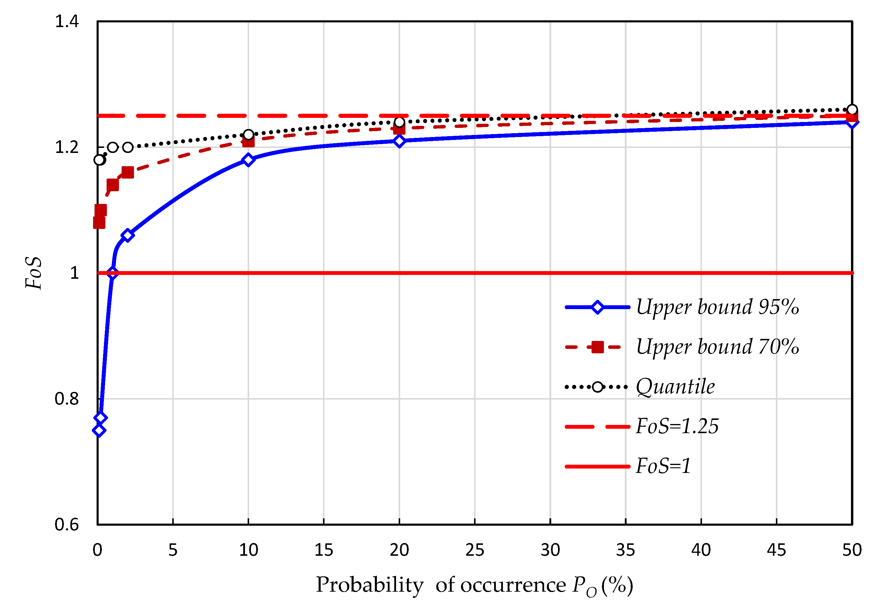
The probabilistic approach is applied for return periods equal to 2, 5, 10, 50, 100, 500 and 1000 years, each associated with a probability of occurrence P O . The liquefaction probability P L is estimated at the top of the sandy layer (soil 2) using data quantiles and upper bounds of the 70% and 95% CIs. Liquefaction likelihood is then determined based on the classification provided in Table 4. Using the F o S values calculated for various return periods, as summarized in Table 5, the hazard curves are plotted in Figure 6.
Close F o S values are provided by the quantiles and upper bounds of the 70% and 95% CIs for short return periods since CIs are narrow for these values and their upper bounds are relatively close to data quantiles. As the return period increases, the CIs widen and the discrepancy between the three estimated F o S values becomes more noticeable.
The results show that no liquefaction hazard is noticed when GWT quantiles and the upper bound of the 70% CI are considered with a F o S threshold set at 1.0. However, when the upper bound of the 95% CI is used, a liquefaction hazard can be observed from a return period equal to 100 years, giving an estimate of P O = 1 % . Assuming herein P L as the probability of occurrence of the event F o S = 1.0 implies that the levee has P L = 1 % associated with GWT depth at about 3.9 m below the crest level. This probability falls within the range of 0 to 15%, within which the liquefaction likelihood is described as “almost certain that it will not liquefy” (class 1, as defined in Table 4). In other words, there is almost a certainty that the sandy layer will not liquefy if the GWT remains at an elevation less than 3.9 m below the crest level during the earthquake.
Setting the F o S threshold at 1.25, as suggested by Eurocode 8, provides, however, more significant estimates of P L , which is assumed herein as the probability of occurrence of the event [ F o S = 1.25 ]. Indeed, P L = 20 % (i.e., a 5-years return period) is obtained at the top of soil 2 when GWT quantiles are used. This P L estimate increases further to reach 50% (i.e., a 2-years return period) and almost 60% (i.e., less than 2-year return period) when upper bounds of the 70% and 95% CIs are used, respectively. These probabilities are determined for the same threshold F o S = 1.25 and approximately associated with the same GWT depth at about 8 m below the levee crest. However, they fall within different ranges of liquefaction likelihood. For the quantiles, P L = 20 % falls within the range 15% to 35%, within which the liquefaction likelihood is described as “unlikely to liquefy” (class 2). When upper bounds of the 70% and 95% CIs are considered, the obtained P L = 50 %   and   P L = 60 % fall within the range 35% to 65%, for which the liquefaction likelihood is described as “liquefaction and no liquefaction are equally likely” (class 3).
From the above results, it can be clearly noted that a conventional liquefaction hazard assessment based on single constant GWT depth estimates can lead to conservative predictions. The use of the most detrimental GWT estimate during an earthquake equal to the canal level provides F o S less than 1.0 ( F o S = 0.87 ) at the top of the sandy layer, reflecting, therefore, a certain liquefaction hazard. The liquefaction likelihood is, however, described as “almost certain that it will not liquefy” based on a probabilistic approach when the upper bound of the 95% CI is used for a threshold   F o S = 1.0 . When this latter is set at 1.25, as suggested by Eurocode 8, no liquefaction and liquefaction at the top of soil 2 become equally likely. This may, in part, explain the overestimation of the liquefaction hazard using the conventional CPT-based method with single assumed GWT estimates, which does not explicitly quantify the spatial and/or temporal variations of design parameters but implicitly covers them through a considerably large margin of safety.
Furthermore, for the same F o S threshold, many liquefaction hazard likelihoods may exist depending on the degree of uncertainty involved in input parameters. For instance, for a specified F o S = 1.25 , P L values ranging from 20% to 60% are obtained, which result in different liquefaction likelihood classes (class 2 and class 3). Therefore, small variations in GWT estimates may not have a noticeable effect on conventional F o S but may lead to significant variations of P L . Consequently, the proposed probabilistic approach can be an important tool to provide complementary useful information to the conventional F o S . This may help geotechnical engineers make more reliable decisions for assessing liquefaction hazard and avoiding unnecessary costs of some earthquake-induced liquefaction hazard mitigation interventions.
However, it is important to mention that these liquefaction hazard predictions are highly dependent on the F o S threshold estimates, as shown in this study and previously noticed by Chen et al. [7]. An increase or decrease of this F o S threshold can result in considerable variations of P L estimates.

4. Conclusions

An earthquake-induced liquefaction assessment is derived in this study for an earthen flood protection levee with consideration of GWT variations over time due to precipitation events. A conventional CPT-based procedure is first applied with constantly assumed GWT estimates during subsurface exploration and the earthquake. The provided results revealed a certain liquefaction potential of a thin sandy layer (soil 2) at the bottom of the levee with F o S < 1.0 when the GWT during the earthquake is assumed to coincide with the water canal level (i.e., at 2 m depth below the crest level). These results were validated through non-linear dynamic analyses developed in GeoStudio 2021 for the same initial conditions.
A probabilistic approach is then applied to take into account the variations of GWT over a time period of 22 years from 1996 to 2018. The Annual Maxima/Generalized Extreme Value (AM/GEV) approach is hence used through a frequency analysis to characterize the distribution of GWT extreme values. Based on field measurements, the GWT during subsurface exploration is kept constant at 8 m depth below the crest level, while the GWT during the earthquake is varied according to GWT scenarios provided by the frequency analysis for many return periods.
Setting the F o S threshold at 1.0, no liquefaction hazard is noticed at the top of the sandy layer when the GWT quantiles and upper bound of the 70% CI are considered. When the upper bound of the 95% CI is used, a liquefaction triggering is observed for a return period equal to 100 years, which implies P L = 1 % . This probability falls within a range where the liquefaction likelihood is described as “almost certain that it will not liquefy”.
Increasing the F o S threshold to 1.25, as suggested by Eurocode 8, increases P L estimates to up to 20% and 60% for GWT data quantiles and upper bound of 95% CI respectively. The former P L value falls within the range, within which liquefaction likelihood is described as “unlikely to liquefy”, which again may seem to contradict the conventional liquefaction hazard prediction. The latter P L value implies no liquefaction and liquefaction evidence at the top of the thin sandy layer (soil 2) is equally likely. This may, in part, explain the overestimation of liquefaction hazard predictions by the conventional simplified method, which does not explicitly quantify the potential uncertainty of design parameters but implicitly covers them through a sufficiently large margin of safety.
The current study showed that, for a fixed F o S threshold, different liquefaction hazard likelihoods may exist depending on the degree of uncertainty involved in GWT estimates. This demonstrates on one hand the effect of GWT data quality on the accuracy of liquefaction hazard predictions, and on the other hand, the importance of the proposed probabilistic approach as a crucial and more informative tool to be used for structures design and risk assessment. Indeed, general practices in liquefaction assessment often ignore the GWT uncertainty and either use constant GWT estimates during both subsurface exploration and design earthquakes or assume a one-groundwater-table (OGT) scenario with the same GWT estimate. These GWT estimates, made based on sparse and incomplete borehole measurements, are mostly unreliable and may result in doubtful liquefaction assessments.
The practical application of the proposed probabilistic methodology is that it provides a straightforward way capable to take into account the complete available GWT level records with their fluctuations over time that may be due to various sources such as precipitation events, climate change, human overexploitation, hydraulic properties of soils, etc. These GWT variations over the time period from 1996 to 2018 are shown to have a significant effect on liquefaction hazard predictions and highlight hence the need for time-dependent liquefaction-hazard assessment of earthen levees. Moreover, using the proposed probabilistic approach with different F o S thresholds allows accounting for various degrees of uncertainty that may be involved in input design parameters; a high F o S threshold can be set when significant uncertainty is noticed in input parameters, while a lower F o S threshold can be assumed when more accurate input data is available. Applying the minimum and maximum preconized F o S thresholds may then provide lower and upper bounds of the probabilistic liquefaction hazard predictions, respectively. In this study, considering F o S thresholds equal to 1.0 and 1.25 gives probabilities of liquefaction of 1% and 60% respectively when the upper bound of 95% CI is used. These probabilistic results, in addition to the obtained hazard curves, are used to provide geotechnical engineers with insight for more reliable decision-making and cost-effective mitigation plans for the earthen levee. It is noteworthy to mention that the findings of the proposed probabilistic methodology are limited to the specifically investigated levee and still need to be validated through either experimental results or more advanced numerical modeling.
The present study has been carried out involving GWT variations over time during earthquakes using fictional constant seismic data with a magnitude and peak ground acceleration set at 5.3 and 0.25 g, respectively. Admittedly, more reliable liquefaction hazard predictions could be provided by the probabilistic methodology if uncertainties in soil properties and input ground motion are taken into account.

Author Contributions

Conceptualization, M.S.; methodology, software, M.S. and Y.H.; validation, formal analysis, investigation, data curation, M.S., Y.H. and D.M.; writing—original draft preparation, M.S.; writing—review and editing, Y.H. and D.M. All authors have read and agreed to the published version of the manuscript.

Funding

This research received no external version.

Institutional Review Board Statement

Not applicable.

Informed Consent Statement

Not applicable.

Data Availability Statement

Not applicable.

Conflicts of Interest

The authors declare no conflict of interest.

References

  1. ASCE. So, You Live behind a Levee! American Society of Civil Engineers: Reston, VA, USA, 2009. [Google Scholar]
  2. Barbetta, S.; Camici, S.; Bertuccioli, P.; Palladino, M.R.; Moramarco, T. Levee body seepage: A refinement of an expeditious procedure for fragility curves and vulnerability diagrams’ assessment. Hydrol. Res. 2017, 48, 763–775. [Google Scholar] [CrossRef] [Green Version]
  3. Mallakpour, I.; Sadegh, M.; AghaKouchak, A. Changes in the exposure of California’s levee-protected critical infrastructure to flooding hazard in a warming climate. Environ. Res. Lett. 2020, 15, 064032. [Google Scholar] [CrossRef]
  4. Kwak, D.Y.; Mikami, A.; Brandenberg, S.J.; Stewart, J.P. Ground motion estimation for evaluation of levee performance in past earthquakes. In Proceedings of the 9th International Conference on Urban Earthquake Engineering/4th Asia Conference on Earthquake Engineering, Tokyo Institute of Technology, Tokyo, Japan, 6–8 March 2012. [Google Scholar]
  5. Serre, D.; Maurel, P.; Peyras, L.; Diab, Y. A spatial decision support system to optimize inspection, maintenance and reparation operations of river levees. In Proceedings of the International Conference on Computing and Decision Making in Civil and Building Engineering, Montréal, Canada, QC, 14–16 June 2006. [Google Scholar]
  6. Jasim, F.H.; Vahedifard, F.; Alborzi, A.; Moftakhari, H.; AghaKouchak, A. Effect of Compound Flooding on Performance of Earthen Levees. In Proceedings of the Geo-Congress GSP 316, Minneapolis, MN, USA, 25–28 February 2020. [Google Scholar]
  7. Chen, J.; O-tani, H.; Takeyama, T.; Oishi, S.; Hori, H.M. A Probabilistic Liquefaction Hazard Assessment for Urban Regions Based on Dynamics Analysis Considering Soil Uncertainties. J. Earth Sci. 2021, 32, 1129–1138. [Google Scholar] [CrossRef]
  8. Seed, R.B.; Bea, R.G.; Abdelmalak, R.I.; Athanasopoulos-Zekkos, A.; Boutwell, G.P.; Briaud, J.L.; Cheung, C.; Cobos-Roa, D.; Ehrensing, L.; Govindasamy, A.V.; et al. New Orleans and Hurricane Katrina. I: Introduction, Overview, and East Flank. J. Geotech. Geoenviron. Eng. 2008, 134, 701–717. [Google Scholar] [CrossRef] [Green Version]
  9. Sasaki, Y.; Towhata, I.; Miyamoto, K.; Sherato, M.; Narita, A.; Sasaki, T.; Sako, S. Reconnaissance report on damage in and around river levees caused by the 2011 off the pacific coast of Tohoku earthquake. Soils Found. 2012, 52, 1016–1032. [Google Scholar] [CrossRef] [Green Version]
  10. Kramer, S. Geotechnical Earthquake Engineering; Prentice-Hall: Upper Saddle River, NJ, USA, 1996. [Google Scholar]
  11. Seed, H.B.; Idriss, I.M. Simplified procedure for evaluating soil liquefaction potential. J. Soil Mech. Found. Div. 1971, 97, 1249–1273. [Google Scholar] [CrossRef]
  12. Youd, T.L.; Idriss, I.M.; Andrus, R.D.; Arango, I.; Castro, G.; Christian, J.T.; Dobry, R.; Liam Finn, W.D.; Harder, L.F., Jr.; Hynes, M.E.; et al. Liquefaction resistance of soils summary report from 1996 NCEER and 1998 NCEER/NSF workshops on evaluation of liquefaction resistance of soils. J. Geotech. Geoenviron. Eng. 2001, 127, 817–833. [Google Scholar] [CrossRef] [Green Version]
  13. Ulusay, R.; Kuru, T. 1998 Adana-Ceyhan (Turkey) earthquake and a preliminary microzonation based on liquefaction potential for Ceyhan town. Nat. Hazards 2004, 32, 59–88. [Google Scholar] [CrossRef]
  14. Idriss, I.M.; Boulanger, R.W. Soil Liquefaction during Earthquakes; Earthquake Engineering Research Institute: Oakland, CA, USA, 2008. [Google Scholar]
  15. Dixit, J.; Dewaikar, D.M.; Janjid, R.S. Assessment of liquefaction potential index for Mumbai city. Nat. Hazards Earth Syst. Sci. 2012, 12, 2759–2768. [Google Scholar] [CrossRef] [Green Version]
  16. Juang, C.H.; Ching, J.; Wang, L.; Khoshnevisan, S.; Ku, C.S. Simplified procedure for estimation of liquefaction-induced settlement and site-specific probabilistic settlement exceedance curve using cone penetration test (CPT). Can. Geotech. J. 2013, 500, 1055–1066. [Google Scholar] [CrossRef]
  17. Chung, J.W.; Rogers, J.D. Influence of assumed groundwater depth on mapping liquefaction potential. Environ. Eng. Geosci. 2013, 19, 377–389. [Google Scholar] [CrossRef]
  18. Molina-Gómez, F.; Bulla-Cruz, L.A.; Moreno-Anselmi, L.A.; Ruge, J.C.; Arévalo-Daza, C. Assessment of groundwater level variations using multivariate statistical methods. Ing. Investig. 2019, 39, 36–42. [Google Scholar] [CrossRef] [Green Version]
  19. Tyagunov, S.; Vorogushyn, S.; Jimenez, C.M.; Stefano Parolai, S.; Fleming, K. Mult-hazard fragility analysis for fluvial dikes in earthquake- and flood-prone areas. Nat. Hazards Earth Syst. Sci. 2018, 18, 2345–2354. [Google Scholar] [CrossRef] [Green Version]
  20. Chang, M.; Chan, M.S.; Huang, R.C.; Upomo, T.C.; Kusumawardani, R. Assignment of groundwater table in liquefaction analysis of soils. In Advancement in Geotechnical Engineering; The official 2020 publications of the Soil-Structure Interaction Group in Egypt (SSIGE), Egypt; Springer: Berlin/Heidelberg, Germany, 2020; pp. 3–18. [Google Scholar]
  21. Haase, J.S.; Choi, Y.S.; Nowack, R.L. Liquefaction hazard near the Ohio River from Midwestern scenario earthquakes. Environ. Eng. Geosci. 2011, 17, 165–181. [Google Scholar] [CrossRef]
  22. Holzer, T.L.; Noce, T.E.; Bennett, M.J. Liquefaction probability curves for surficial geologic deposits. Environ. Eng. Geosci. 2011, 17, 1–21. [Google Scholar] [CrossRef]
  23. Robertson, P.K.; Campanella, R.G.; Gillespie, D.; Greig, J. Use of Piezometer Cone data. In Proceedings of the ASCE, In-Situ’86 Use of Ins-itu testing in Geotechnical Engineering, Blacksburg, VA, USA, 23–25 June 1986; pp. 1263–1280. [Google Scholar]
  24. Robertson, P.K.; Wride, C. Evaluating Cyclic Liquefaction Potential Using the Cone Penetration Test. Can. Geotech. J. 1998, 35, 442–459. [Google Scholar] [CrossRef]
  25. Liao, S.S.C.; Veneziano, D.; Whitman, R.V. Regression model for evaluating liquefaction probability. J. Geotech. Eng. 1988, 114, 389–410. [Google Scholar] [CrossRef]
  26. Seed, R.B.; Idriss, I.M. Ground Motions and Soil Liquefaction during Earthquakes; Engineering monographs on earthquake criteria, structural design and strong motion records; Earthquake Engineering Research Institute: Berkeley, CA, USA, 1982. [Google Scholar]
  27. Weibull, W. A statistical theory of strength of materials. Ingeniôrsvetenskapsakademiens Handl. 1939, 151, 1–45. [Google Scholar]
  28. Jenkinson, A.F. The frequency distribution of the annual maximum (or minimum) values of meteorological elements. Q. J. R. Meteorol. Soc. 1955, 81, 158–171. [Google Scholar] [CrossRef]
  29. Fisher, R.A.; Tippett, L.H.C. Limiting forms of the frequency distribution of the largest or smallest member of a sample. In Mathematical Proceedings of the Cambridge Philosophical Society; Cambridge University Press: Cambridge, UK, 1928; Volume 24, pp. 180–190. [Google Scholar]
  30. Iai, S.; Tsuchida, H.; Koizumi, K. A new criterion for assessing liquefaction potential using grain size accumulation curve and N-value. Rep. Port Harb. Res. Inst. 1986, 25, 125–234. [Google Scholar]
  31. Robertson, P.K. Soil classification using the cone penetration test. Can. Geotech. J. 1990, 27, 151–158. [Google Scholar] [CrossRef]
  32. Das, S.K.; Muduli, P.K. Probability-based method for assessing liquefaction potential of soil using genetic programming. In Proceedings of the International Symposium on Engineering under Uncertainty: Safety Assessment and Management (ISEUSAM), Kolkata, India, 4 January 2013. [Google Scholar]
Figure 1. Cross-section of the earthen flood protection levee.
Atmosphere 13 01741 g001
Figure 2. Example of profiles of tip resistance q c   and normalized friction ratio F with depth.
Atmosphere 13 01741 g002
Figure 3. Acceleration time history of the simulated earthquake.
Atmosphere 13 01741 g003
Figure 4. Factor of safety F o S for the simulated earthquake.
Atmosphere 13 01741 g004
Figure 5. Quantiles and confidence intervals of GWT levels.
Atmosphere 13 01741 g005
Figure 6. Hazard curves for the quantiles and upper bounds of 70% and 95% CIs.
Atmosphere 13 01741 g006
Table 1. Geotechnical properties of levee layers.
SoilThickness (m) γ   kN / m 3 c   kPa   * φ °   * * Permeability   k m / s
Soil 110222528 10 6
Soil 2119035 10 5
Soil 3320038 10 4
* Soil cohesion; ** Soil friction angle.
Table 2. Cyclic resistance ratio CRR.
Depth (m) σ v 0 ( kPa ) U
(kPa)
σ v 0 ( kPa ) F
(%)
Q ( n = 1 ) I c ( n = 1 ) Q ( n = 0.5 ) I c (n = 0.5) n I c     * q c 1 N K c q c 1 N C S C R R 7.5 M S F C R R M w
1.022.00-22.002.5884.112.0386.35 2.24 0.502.24 86.35 1.77 152.80 0.41 2.43 1.01
2.044.00-44.001.9191.842.1360.92 2.26 0.502.26 60.92 1.82 110.77 0.21 2.43 0.51
3.066.00-66.001.2461.082.1449.62 2.21 0.502.21 49.62 1.69 83.66 0.13 2.43 0.33
4.088.00-88.001.2325.222.4523.66 2.47 0.502.47 23.66 2.63 62.22 0.10 2.43 0.25
5.0110.00-110.000.9941.522.2143.55 2.20 0.502.20 43.55 1.66 72.32 0.12 2.43 0.28
6.0132.00-132.000.8328.732.3133.01 2.26 0.502.26 33.01 1.83 60.25 0.10 2.43 0.25
7.0154.00-154.001.00 47.442.1758.87 2.09 0.502.09 58.87 1.44 84.86 0.14 2.43 0.34
8.0176.00-176.001.1434.992.3146.42 2.21 0.502.21 46.42 1.69 78.47 0.12 2.43 0.31
9.0198.009.81188.191.5334.122.3946.812.28 0.502.28 46.81 1.89 88.70 0.14 2.43 0.36
10.0217.0019.62197.380.927.652.84 --1.002.84 7.65 5.17 39.57 0.08 2.43 0.20
10.5226.5024.53201.981.219.762.80 --1.002.80 9.76 4.79 46.79 0.09 2.43 0.22
11.0236.5029.43207.071.1913.121.92 162.79 1.81 0.501.81 162.79 1.11 180.98 0.63 2.43 1.55
12.0256.5039.24217.260.9013.221.84 166.89 1.71 0.501.71 166.89 1.05 174.84 0.58 2.43 1.42
13.0276.5049.05227.450.6455.342.01 83.47 1.86 0.501.86 83.47 1.15 96.14 0.16 2.43 0.40
14.0296.5058.86237.640.6332.411.69 204.12 1.54 0.501.54 204.12 1.00 204.12 0.87 2.43 2.14
* It is important to mention that the provided Ic (also called SBT Soil Behaviour Type) values of soil 2 indicate a soil behaviour type of sands-to-sand mixtures [31].
Table 3. Cyclic stress ratio CSR and factors of safety F o S .
Depth
(m)
σ v 0
KPa
U
(kPa)
σ v 0
KPa
r d C S R
  0.25   g
F o S  
0.25   g
1.022.00-22.000.990.166.21
2.044.00-44.000.980.163.14
3.066.009.8156.190.980.191.75
4.088.0019.6268.380.970.201.23
5.0110.0029.4380.570.960.211.31
6.0132.0039.2492.760.950.221.11
7.0154.0049.05104.950.950.231.47
8.0176.0058.86117.140.940.231.33
9.0198.0068.67129.330.930.231.52
10.0217.0078.48138.520.910.230.87
10.5226.5083.39143.120.890.230.94
11.0236.5088.29148.210.880.23Non-liquefiable
12.0256.5098.10158.400.850.22Non-liquefiable
13.0276.50107.91168.590.830.221.79
14.0296.50117.72178.780.800.22Non-liquefiable
Table 4. Liquefaction likelihood classification [32].
Class Probability   of   Liquefaction   ( P L ) Description of Likelihood
5 P L ≥0.85Almost certain that it will liquefy
40.65 ≤ P L < 0.85Very likely to liquefy
30.35 ≤ P L < 0.65Liquefaction and no liquefaction are equally likely
20.15 ≤ P L   < 0.35Unlikely to liquefy
1 P L < 0.15Almost certain that it will not liquefy
Table 5. F o S of the quantiles and upper bounds of the 70% and 95% CIs.
Return Period
(Years)
Probability   P O   ( % ) F o S
Quantiles
F o S
Upper Bound 70%
F o S
Upper Bound 95%
2501.261.251.24
5201.251.231.21
10101.221.211.18
5021.201.161.06
10011.201.141.00
5000.21.181.100.77
10000.11.181.080.75
Publisher’s Note: MDPI stays neutral with regard to jurisdictional claims in published maps and institutional affiliations.