Abstract
The aim of this contribution is to design and test the lightning protection of an aircraft radome exposed to direct lightning strikes. The influencing parameters are investigated on different radome wall samples equipped with solid and segmented diverter strips. The effectiveness of the lightning interception and protection measures is tested with different high-voltage waveforms and representative high-current pulses. The tests show that reliable radome lightning protection can be achieved by an optimized arrangement of solid and segmented diverter strips, even if the aircraft radome has a huge size, with dimensions up to several meters.
1. Introduction
Lightning starts with processes in which charges inside the thundercloud are separated and rearranged. Due to these processes, the negative and positive charges are accumulated in a lower negative and a higher positive charge center. When the amount of charge exceeds a certain critical value, the electric field becomes so intense that a (positive or negative) leader is formed which propagates out of the charge center. If the leader arrives on the ground, this is the beginning of a so-called downward flash or cloud-to-ground lightning. A cloud flash or cloud-to-cloud-lightning occurs whenever the leader terminates at the inverse charge center of a neighboring thundercloud [1,2].
As soon as an aircraft comes close to the path of such lightning, the lightning channel is diverted to the aircraft and the aircraft becomes part of the lightning path. The first current component is always produced by a return stroke process. This component is a strong impulsive current which lasts typically several hundreds of microseconds and has a peak value ranging from several tens up to more than a hundred kiloamps. The return stroke current may be followed by a continuing current, which typically lasts some tens to some hundreds of milliseconds and has an amplitude of some tens to some thousands of amperes. The first return stroke may be followed by a series of subsequent return strokes and each of them may be followed by a continuing current [1,2,3,4].
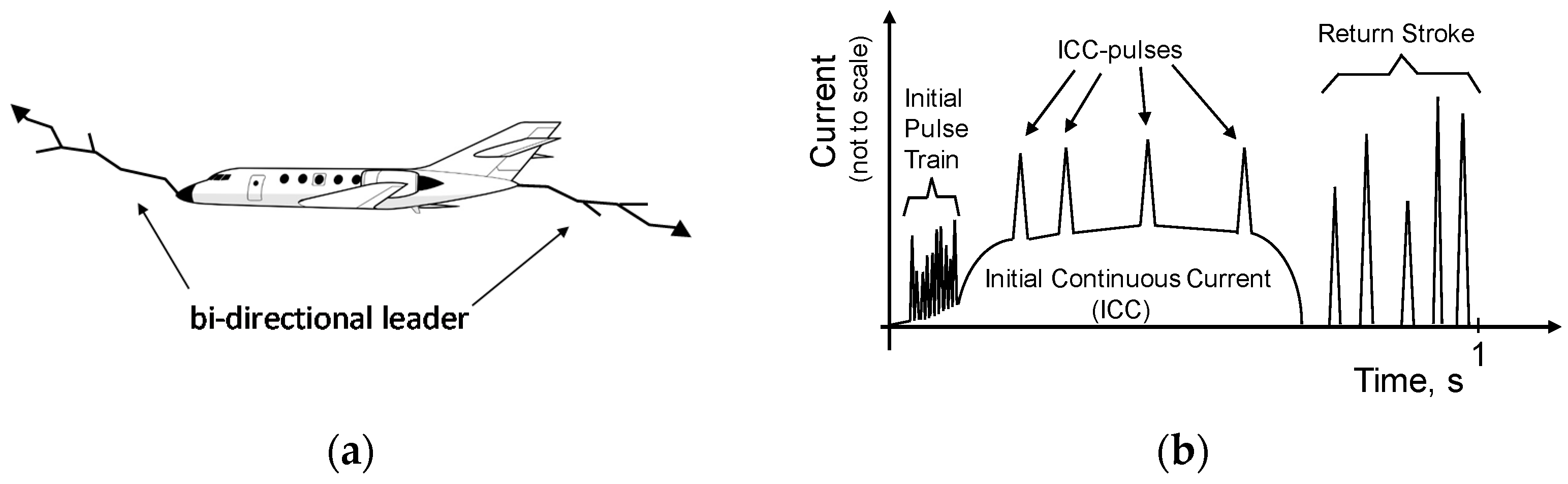
This scenario describes the interception by the aircraft of already occurring natural cloud-to-cloud or cloud-to-ground lightning. However, measurements during the 1980s from three instrumented aircrafts (types: F106, CV580, and C160) revealed that this (first) scenario was valid only for about 10% of the lightning reaching an aircraft [5,6,7]. The most frequent scenario (about 90% of recorded events) involves lightning triggered by the aircraft itself. This may happen when the aircraft flies in regions where the ambient electric field is so intense that a leader starts from the aircraft in the direction of the ambient electric field. A few milliseconds later this leader is followed by a second leader of inverse polarity which develops in the opposite direction. In this way, a bi-directional leader is formed, as shown in Figure 1a [6,7].

Figure 1.
(a) Bi-directional leader at the initial phase of the lightning interception; (b) Schematic diagram of a typical lightning current waveform (adopted from [6]).
The bi-directional leader produces an initial continuous current (ICC) which flows along the structure of the aircraft. Figure 1b shows a typical lightning current waveform deduced from currents of in-flight lightning strikes [6]. The stepping of the bi-directional leader appears in the current waveform as a current pulse train at the beginning of the slowly increasing ICC. The ICC lasts typically some tens to some hundreds of milliseconds and has an amplitude of some tens to some hundreds of amperes. The ICC may be superimposed by ICC-current pulses, and it may be followed by a series of current pulses produced from subsequent return strokes.
The objective of the paper is to present the protection measures and necessary experimental procedures needed for the lightning protection design of aircraft radome exposed to direct lightning strikes. The countermeasures include both scenarios: firstly the scenario that the aircraft becomes part of already occurring natural lightning, and secondly that the aircraft triggers the lightning itself.
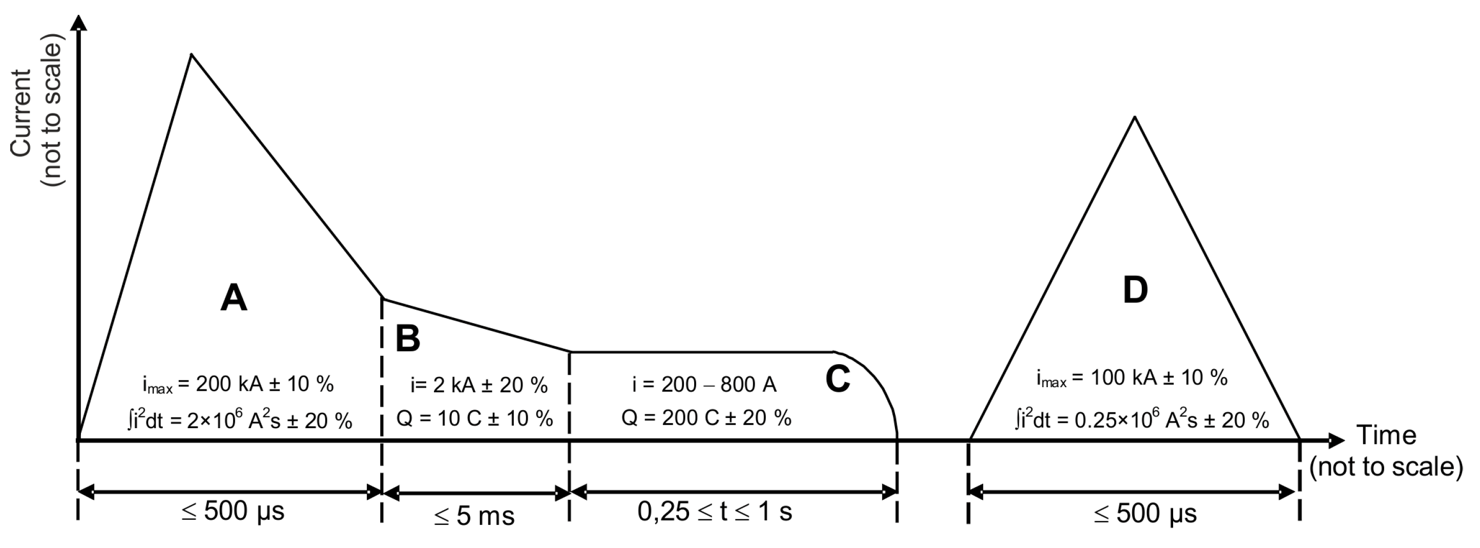
Based on these requirements, in the international standards a lightning current is specified which contains four current components, as shown in Figure 2 [8,9,10,11,12]. The current component A combines the severe parameters of the negative and positive first return stroke that are observed in cloud-to-ground lightning. Component B and component C represent the ICC and the continuing current that are observed in aircraft-triggered lightning and in cloud-to-ground lightning, respectively. Finally, component D represents the threat by the current of the subsequent return stroke.
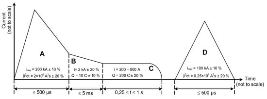
Figure 2.
Current components A–D for direct lightning testing, adopted from [8].
Studies showed that the structural damage of composite structures caused by lightning strikes is mainly caused by transient lightning current components [13,14,15]. The transient waveform A is responsible for the (resistive) heating and for diverse mechanical forces which may cause damage to the structure of the aircraft. Therefore, component A was applied for the high-current (HC) radome tests described in this contribution.
The current waveform A is defined by the:
- Peak current: imax = 200 kA ± 10%,
- Action integral: ∫ i2dt = 2 × 10⁶ A2s ± 20%,
- Time duration: Tend ≤ 500 µs, and finally
- Time to crest: T1 ≤ 50 μs.
The primary task of the diverter strips is to intercept the lightning flash. The interception of the lightning flash is associated with the breakdown process of the electric field in connection with the development of the bi-directional leader. High-voltage (HV) testing that reproduces that process is used to prove the functionality of the lightning protection system. The wide range of the electric field is considered using four distinct HV waveforms, i.e., the voltage waveforms A, B, C, and D according to the reference [8].
However, HV tests with the voltage waveform C are not required in the present case. Therefore, the investigations were restricted to voltage waveforms A, B, and D, presented in Figure 3. The voltage waveform A rises at a rate of dV/dt = 1MV/μs (±50%), the voltage waveform B represents a voltage impulse with a front time of 1.2 µs (±20%) and a decay time to half-value of 50 µs (±20%), and the voltage waveform D represents a slow-rising voltage impulse with a front time of 50 µs to 200 µs and a decay time to half-value of about 2000 µs. Nowadays it is assumed that the slow waveform D is the most representative of electric field development at an aircraft extremity during the initial lightning attachment phase [16,17,18]. The fast waveform A is added since it is probably most representative of the electric field associated with lightning re-attachment to aircraft surfaces and the radome, located in the swept leader and swept channel zones, respectively.
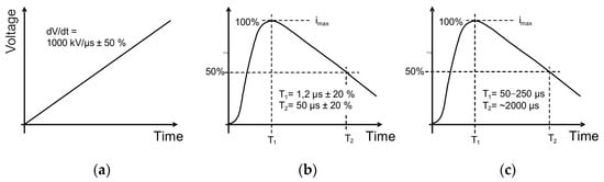
Figure 3.
(a) Voltage waveform A, (b) voltage waveform B, and (c) voltage waveform D, adopted from reference [8].
The lightning protection system has to be designed in such a way that puncture of the radome wall is prevented and damage to the antenna-system located inside is avoided. Moreover, the lightning protection system should not have significant impact on the antenna pattern. For this purpose, lightning protection is realized by so-called solid or segmented diverter strips generally located on the outer surface of the radome. Segmented strips are used wherever the impact on the antenna pattern should be completely negligible. Otherwise, if that is not required, solid diverter strips are preferred.
Two different types of segmented diverter strips are used to find the best design for the lightning protection of the aircraft sitcom radome under consideration. The first type LDS 10-01-38 consists of a series of round metallic buttons with a diameter of 1.52 mm. The second, of type LDS 10-01-09, uses buttons with the diameter of 0.76 mm [19].
Based on these HV investigations, a full-scale satcom radome prototype was designed including an antenna model located inside. The radome was equipped with a hybrid lightning protection system consisting of solid and segmented diverter strips. For the design of the lightning protection, the recommendations for electrically non-conducting aircraft structures were also considered [20,21,22,23,24]. To prove the effectiveness of the lightning interception, the full-scale radome was tested with the slow-rising high-voltage waveform D. Because the slow-varying double waveform D commonly covers the most critical case, this voltage waveform was selected in [25], although natural electric field pulses may have a concave waveform. The tests were verified using the fast-rising high-voltage waveform B. Finally, the current carrying capacity of the designed lightning protection measure was tested. For this purpose, the lightning current component A was applied to two samples. One used a design based on a segmented diverter strip, while the other used a combination of a solid and a segmented diverter strip.
2. Design of Lightning Protection of an Aircraft Radome
The effectiveness of the lightning protection system of an aircraft radome depends on the dielectric strength of the radome wall, on the type and arrangement of the diverter strips, on the size and shape of the radome, and finally on the size and position of the antenna inside the radome. The radome wall may consist of solid material (monolithic design) or of a sandwich panel structure. In the present case, the investigations are concentrated to 2 A-sandwich panels with different thicknesses of the honeycomb core.
2.1. Dielectric Strength of a Sandwich Panel Structure
The breakdown voltage characterizes the dielectric strength and thus the lightning protection effectiveness of the radome wall structure. The breakdown voltage was evaluated applying the test voltages with the waveforms A, B, and D to 2 representative samples. The tested samples were A-sandwich panels: 1 with a core thickness of 14 mm, and the other with the core thickness of 20 mm (see Table 1). The core was made from fiberglass-reinforced honeycomb. The skins were glass-fiber reinforced plastic (GFRP) laminates with the thickness of 0.9 mm. Figure 4a shows the test setup with the HV electrode and the sandwich sample.

Table 1.
Average breakdown voltage for the 2 types of sandwich panels. The standard deviations are given in brackets.
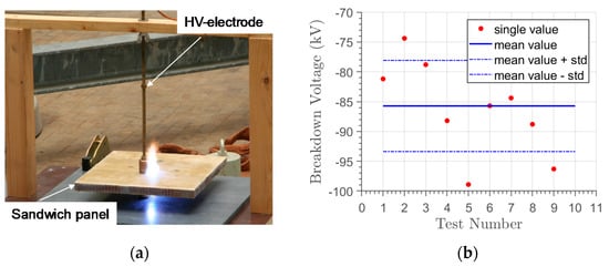
Figure 4.
(a) Test setup with sandwich sample; (b) Breakdown voltage of radome sample with the core thickness of 20 mm using waveform D.
The tests revealed that the breakdown voltage can vary in a wide range. Figure 4b exemplarily shows the breakdown voltage for a sample with the core thickness of 20 mm. In 9 individual tests using high-voltage waveform D, the breakdown voltage varied between 74 kV and 99 kV.
Table 1 summarizes the results of the voltage tests with waveforms A, B, and D. The values represent the arithmetic means based on at least 5 individual tests at each sample used. The breakdown voltage tests were performed at different locations on the sample with a minimum spacing of 100 mm. A total of 16 identical A-sandwich samples were tested. Table 1 presents the average values of the measured data and the standard deviations (given in brackets). The test results indicate that the breakdown voltage decreased with decreasing core thickness and decreasing rate of the rise of the voltage. This finding suggests that the slow-rising voltage impulse of waveform D represents the most critical case.
2.2. Characteristics of the Segmented Diverter Strips
Figure 5 shows the schematic drawing of a sandwich panel equipped with solid (Figure 5a) and segmented (Figure 5b) diverter strips. As described above, the A-sandwich panel consists of a honeycomb core located between 2 laminates of GFRP.

Figure 5.
Schematic drawing of the design of a sandwich panel equipped with (a) solid and (b) segmented diverter strips.
Solid strips are usually fastened by screws or bolts on the sandwich panel and on the aircraft structure. The segmented diverter strips consist of a series of small buttons placed on a thin insulating substrate. The buttons are made of copper alloy and coated by a thin nickel layer. The insulating substrate is fastened to the sandwich by a glue and the end of the strip is connected to the aircraft structure by a screw or a bolt.
For applications where the impact of the lightning protection system on the antenna radiation pattern is critical, segmented diverter strips are preferred. Otherwise, solid diverter strips are used which are comparable to the air termination and downward system of buildings [26,27]: They consist of a thin solid metallic bar which intercepts the lightning and makes the contact to the aircraft structure. The cross-sectional area of the metallic material used is determined by the lightning current load (usually high-current component A). Solid diverter strips have the advantage that they can resist several lightning strikes, in contrast to segmented diverter strips which can withstand only a very limited number of lightning events.
The small buttons of the segmented diverter strips are placed on the insulating substrate with a very small distance in between. The small distance between the buttons builds up a series of spark gaps which are triggered whenever the ignition voltage is exceeded. After the breakdown of the voltage, plasma is formed which builds up an illuminated channel along the segmented diverter strips, as shown in Figure 6a. Plasma ignition at low voltage is required for high lightning protection effectiveness. For this reason, painting of the segmented diverter strips is not permitted, as it would impede plasma ignition. Segmented diverter strips have also the disadvantage that the ignition of the plasma channel is strongly influenced by external environmental conditions such as reduced air pressure at high altitude or rain, ice, etc. The segmented diverter strips can be covered by layers of water/ice with thicknesses ranging from a few mm to about 15 mm; the cascade disruptive discharge (that usually occurs in air) is weakened and the ignition voltage is increased significantly [28]. In contrast, the solid diverter strips do not have such limitations and they may be painted without reducing the effectiveness of the lightning protection [20,28].
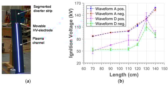
Figure 6.
(a) A test setup with an ignited segmented diverter strip, and (b) the average ignition voltage as a function of strip length.
In former designs, a resistive strip was used on the backside of the segmented diverter strip. Nowadays, resistive strips are no longer in use since they may impede the plasma ignition of the strip. Larger segments have lower breakdown voltages, but smaller segments can better withstand high current loads. A further requirement is that the size of the buttons should be considerably smaller than the wavelength of operating antenna to avoid significant effects on the antenna pattern.
The influence of the length of the diverter strip on the ignition voltage was examined with the test setup shown in Figure 6a. The strip length (length of the tested section of the diverter strip) was adjusted by a movable HV electrode. The tests were performed using the voltage waveforms A and D, with positive and negative polarity, respectively.
In Figure 6b, the test results are exemplarily presented for the diverter strip of type LDS 10-01-38 [19]. The diagram shows that the ignition voltage (average value) increases with increasing length of the strip, which was varied between 70 cm and 140 cm. The standard deviation values are also shown in Figure 6b. The values represent the arithmetic means based on at least 5 individual tests for positive and negative polarity at each sample length. In total, over 120 HV tests were performed for the diverter strip of type LDS 10-01-38. The investigations suggest that the voltage per length needed to ignite a plasma channel above the LDS 10-01-38 segmented strip is roughly 1 kV/cm for the fast voltage waveform A and 0.75 kV/cm for the slow voltage waveform D.
2.3. Maximum Admissible Length of the Segmented Diverter Strip
The ignition voltage (along the complete diverter strip) should generally be less than the breakdown voltage of the radome structure to prevent puncturing of the radome wall. Because the ignition voltage increases with strip length, the maximum admissible strip length depends on the design of the radome wall as well as the size and the location of the antenna inside the radome.
For the evaluation of the maximum admissible strip length, the real antenna was substituted by a mock-up antenna model with the same size as the real antenna. Figure 7 shows the schematic drawing of the test setup from the top and from the side. The strip length (length of the tested section of the diverter strip) is adjusted by a movable HV-electrode. The antenna model is grounded and located at the relevant distance (d) away from the rear side of the radome wall. The chosen distance d corresponds to the minimum distance of the antenna to the inner radome wall structure of the satcom radome shown in Figure 8.
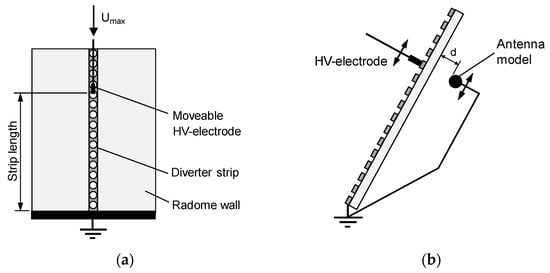
Figure 7.
Schematic drawing of the test setup for the evaluation of the admissible length of the diverter strip: (a) top view and (b) from the side.
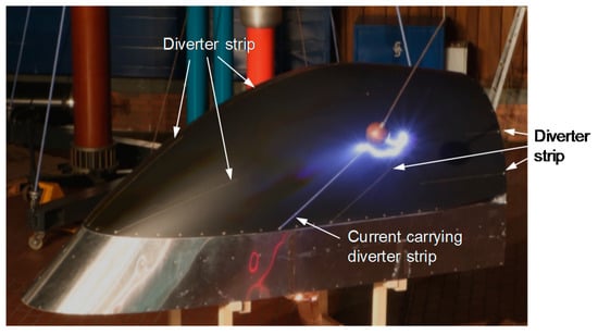
Figure 8.
Image of the SATCOM radome prototype during the test with waveform D [29].
The strip length was increased step by step until the ignition voltage was so high that the radome wall was punctured, and an arc was formed from the HV electrode to the antenna model. The last position without breakdown determines the maximum admissible length of the segmented diverter strip. In Table 2, the test data are exemplarily presented for the segmented diverter strip of type LDS 10-01-38. For the tests, the HV waveform A (1000 kV/µs) was chosen with negative polarity. Again, the measured values of the ignition voltage (Umax) scattered significantly. However, puncturing of the radome wall structure occurred only for distances of more than 100 cm when the ignition voltage (Umax) exceeded 122.8 kV. Therefore, the maximum admissible length of the diverter strip was fixed to 100 cm in this case (for the considered waveform and polarity).
Table 2.
Evaluation of the maximum admissible strip length by applying the HV waveform A (1000 kV/µs) of negative polarity.
2.4. Maximum Admissible Interspacing between 2 Segmented Diverter Strips
The interspacing between 2 diverter strips should be small enough to prevent arcing through the radome wall to the antenna inside. For this purpose, the maximum admissible interspacing was investigated with the test setup shown in Figure 9. The test setup corresponds to test setup C suggested in [10]. The test setup uses 2 segmented diverter strips which are fixed on the radome panel in parallel at the distance D. Again, the antenna model was placed at the rear side of the radome panel at the relevant distance d. The HV electrode was adjusted in the height a above the radome panel, midway between the diverter strips. The distance D ranged between 40 and 80 cm. It should be noted that the distance must be adapted to the chosen distance D so that a ≥ D.
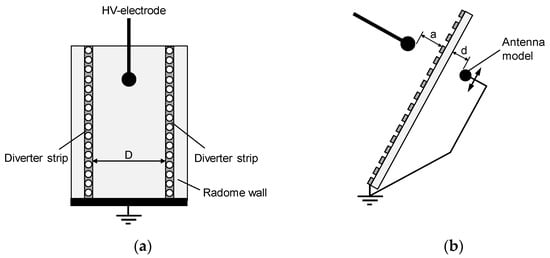
Figure 9.
Schematic drawing of the test setup for the evaluation of maximum admissible interspacing between 2 diverter strips: (a) top view and (b) from the side.
Starting with a small distance, the interspacing was increased step by step until the radome wall was punctured by an arc discharge. The last position without breakdown determines the maximum admissible diverter interspacing. The tests were performed with the voltage waveforms A and D, with positive and negative polarity. The tests revealed that the voltage waveform D with positive polarity represents the most critical case [16,17,29]. Puncturing of radome wall occurred when the interspacing exceeded 50 cm. Therefore, this distance of 0.5 m represents the maximum admissible interspacing between 2 segmented diverter strips for the considered situation (planar radome wall structure, segmented diverter strip, and the antenna).
3. High-Voltage Tests with a Full-Scale Radome
High-voltage tests were performed with a full-scale satcom radome prototype at the Nikola Tesla Laboratory of the Institute of High Voltage Engineering of Graz University of Technology [29]. The high-voltage tests simulate the initial leader attachment process. The full-sized structure is necessary to determine the locations where initial lightning attachment may occur and to detect specific locations where the lightning protection system can fail and puncturing may be possible.
The full-scale satcom radome prototype has a huge size, with dimensions up to about 5 m. It is placed on a moveable trolley to enable lightning tests from different positions. On the radome a lightning protection system was installed which consists of a combination of solid and segmented diverter strips.
The test results show that reliable lightning interception can be achieved by an optimized arrangement of solid and segmented diverter strips even in the case of such a huge radome structure. Figure 8 shows an example for the high-voltage tests with an electrode which was placed at different locations above the radome prototype. The arc was successfully redirected to 1 segmented diverter strip (although a creeping of the plasma channel on the radome surface was observed in this particular case). The tests were performed with high-voltage waveform D and positive and negative polarity, following the recommendations of reference [16,17]. The test results were verified using high-voltage waveform B.
4. High-Current Tests at Radome Samples
The high-current (HC) tests were performed with the current component A at the High-Voltage Institute of the University of the Federal Armed Forces Munich [30]. The continuing current (component C) will certainly increase the thermal damage on the surface of the radome wall structure. However, the radome is not exposed to the full component C, but to the reduced component C * due to the swept stroke. Critical mechanical damage to the composite radome wall structure—puncture or delamination—occurs generally during transient lightning current components (component A).
The test generator used was a combination of 2 individual high-current generators, each equipped with 2 capacitor banks of 30 μF. The capacitor banks of this tandem HC generator can be charged up to a maximum voltage of 100 kV. To obtain a unidirectional current waveform, both generators were equipped with crowbar switches. The currents from the generators were added up at the specimen under a test where the total current was measured via a wideband current monitor (type: Pearson Model 2093). Figure 10 shows an example for current component A produced with the tandem generator.
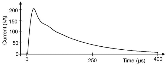
Figure 10.
Example for high-current component A produced with the tandem generator at the University of the Federal Armed Forces Munich [1].
4.1. Design of the Radome Samples
Solid diverter strips can withstand several times the threat of the return stroke current. The use of the segmented diverter strips is more critical, because small buttons may be melted or blown away by the expanding arc of the lightning current. Therefore, high-current tests are focused on 2 types of radome samples, 1 equipped with a segmented diverter strip and the other equipped with a combination of a solid and segmented diverter strip. Figure 11 shows the schematic drawing of both configurations in a top and a side view.
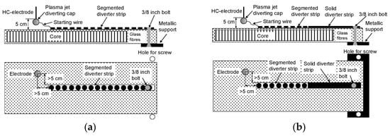
Figure 11.
Schematic drawing (side view and top view) of the test samples equipped with (a) a segmented diverter strip (configuration 1), and (b) a combination of solid and segmented diverter strips (configuration 2).
The first configuration represents a section of a planar radome structure equipped with a segmented diverter strip which is directly connected to the metallic aircraft frame using a metallic grounding bolt (see Figure 11a). The second configuration represents a hybrid protection system consisting of the combination of a solid and a segmented diverter strip. The solid diverter strip was electrically connected to the metallic structure using a metallic grounding bolt. Particular attention was paid to the transition from the segmented to the solid diverter strip (see Figure 11b).
Figure 12 shows the test setup. The HV electrode was placed 50 mm above the test sample and was slightly shifted from the beginning of the segmented diverter strip by more than about 50 mm to avoid plasma jets directed to the diverter strip. For the same reason, the tip of the HV electrode was covered by a spherical cap of insulating material. Further, a very thin starting wire of copper was used to guide the discharge to the beginning of the diverter strip.
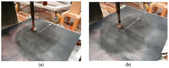
Figure 12.
(a) Front side of sample C1-B (segmented diverter strip) after the first test current (component A), and (b) front side of the sample C2-B (combination of solid and segmented diverter strip) after the second test current (component A).
4.2. Results for the Tested Radome Samples
Two samples of configuration 1 (sample number: C1-A, C1-B) were manufactured, and each was tested with two current pulses of component A. The two lightning loads were applied to each sample to prove whether the designed protection scheme could withstand a single lightning current or whether it could withstand even a multiple strike event.
Table 3 summarizes the test parameters. The considered current parameters were the peak current (Imax), the charge (Q), the front time (T1), the decay time to half-value (T2), the current duration (Te), and the specific energy W/R = ∫i2dt. All applied test currents fulfilled the requirements of current component A regarding the permitted tolerances.
Table 3.
Current parameters during the tests of the 2 samples of configuration 1 (segmented diverter strip).
Table 4 contains the analog data for configuration 2 (a combination of the segmented and solid diverter strip). Again, two samples (sample number: C2-A, C2-B) were manufactured and each of them was tested twice with component A. Furthermore, in this case, all applied high-current pulses fulfilled the requirements of current component A.
Table 4.
Current parameters of the tests of the 2 samples of configuration 2 (combination of segmented and solid diverter strip).
Figure 12a shows the front side of sample C1-B (segmented diverter strip) after the first test current (Component A). After the first test load, (as expected), burn marks were visible on the front side of the sample. The paint was damaged and the surface of some buttons of the diverter strips was melted due to the hot current plasma. However, the function and safety of the segmented diverter strip was not impaired by these small thermal damages (this was proven by the second high-current load).
Figure 12b shows an example for configuration 2 (a combination of solid and segmented diverter strip) after the second current test (component A).
At the tip of the solid diverter strip, the paint was completely removed. Thermal damage was also visible to the paint around the current attachment point and on the surface of the fixing bolt and of the (titanium) screws used for contact with the aircraft structure. It should be noted that segmented diverter strips are generally replaced after one lightning load to avoid the possible failure of the lightning protection system. However, there was no indication of damage to the radome sandwich structure, and there was no visible damage on the rear side of the samples caused by the shock waves of the supersonic expansion of the plasma channel. Ultrasound tests performed after the lightning tests confirm this finding; neither delamination of the GFRP skins and of the honeycomb core nor squeezing of the honeycomb core were found.
5. Conclusions
The magnitude of the electric field inside a dielectric radome is not significantly impacted by the radome wall structure itself. Consequently, the radome does not produce any significant electromagnetic screening effects on the enclosed antenna. To avoid lightning strike inception inside the radome, solid or segmented lightning diverter strips are therefore usually used to produce the necessary electromagnetic shielding effect and/or to trigger the streamer from the tip of the diverter strips.
There are a few general guidelines that should be followed when designing a lightning protection system for non-conducting aircraft structures. The diverter should be oriented as much as possible in the line of flight. This enables swept strokes to follow the diverter as the aircraft moves forward and not jump over the non-conducting structure to be protected. Although the rearward arrangement recommended above is desirable for the reattachment of lightning, there must also be an adequate path for the discharge of the lightning current into the metallic structure. It may therefore be necessary for some of the diverters to not be aligned in the flight line.
Solid diverters should be designed to conduct the lightning current of the zone in which the non-conducting structure is located without significant thermal damage. Typically, solid diverters in zone 1A should withstand a 200 kA current amplitude and a 2 × 10⁶ A2s action integral. The cross-sectional area of solid diverters depends on the material used and the maximum temperature rise specified.
Segmented diverter strips are used in cases where electromagnetic interference with the antenna must be minimized. Segmented diverter strips do not provide a continuous metallic conducting path to directly conduct the lightning current. Segmented strips consist of a series of thin conducting segments attached to a thin dielectric substrate. The size of the buttons is generally chosen in relation to the antenna operating frequency so that the buttons do not noticeably interfere with antenna radiation. However, the segmented strips are not without impact, especially on the side lobes of the antenna pattern.
Diverter strips should be placed neither “too far” nor “too close” from the conducting objects to be protected. The spacing of the diverters depends on the dielectric strength of the structure, the proximity of conducting objects to the non-conducting structure, and the length of the diverter strips. The typical diverter spacing is between 30 cm and 60 cm. Enough strips should be used to ensure that any lightning strike will flash across the surface of the skin of the non-conducting structure rather than puncturing the skin and striking the metallic objects under the skin. The required minimum spacing is generally determined by experiments, as no numerical tools are currently available to determine the minimum spacing of segmented diverter strips on a realistic radome structure. The functioning and effectiveness of a lightning protection measure must finally be verified by high-voltage lightning attachment tests on a full-scale radome to determine whether it is capable of intercepting lightning strikes and prevents puncturing of the dielectric radome wall structure.
In this study, an example of the design of a lightning protection system for an aircraft radome was presented. The hybrid lightning protection system consists of solid and segmented diverter strips. It was shown that the chosen arrangement of diverter strips intercepts reliable lightning flashes, prevents the radome wall structure from puncturing, and avoids arcing to the antenna installed inside the huge satcom radome.
It was further shown that the designed lightning protection system can withstand at least two severe lightning strikes with a current load given by high-current component A. After the high-current tests, only some minor damage was detected. Some traces of thermal damage could be seen on the paint on the front side of the sample. Furthermore, some melt points or traces of melting were visible on the buttons of the diverter strip. However, no damage to the radome sandwich structure, no puncture of the radome wall, and no delamination of the radome skin were detected after the high-voltage and high-current tests.
Author Contributions
Investigation, methodology, resources, data curation, conceptualization, writing—original draft preparation, writing—reviewing and editing, C.K. and F.H.; writing—reviewing and editing, C.P.; supervision, validation, C.K. and F.H. All authors have read and agreed to the published version of the manuscript.
Funding
This Research received no external funding.
Institutional Review Board Statement
Not applicable.
Informed Consent Statement
Not applicable.
Data Availability Statement
Data set available on request to corresponding authors.
Conflicts of Interest
The authors declare no conflict of interest.
References
- Rakov, V.; Uman, M. Lightning: Physics and Effects, 1st ed.; Cambridge University Press: New York, NY, USA, 2003. [Google Scholar]
- Uman, M.A. The Lightning Discharge; Academic Press: San Diego, CA, USA, 1987. [Google Scholar]
- Berger, K.; Anderson, R.B.; Kroeninger, H. Parameters of Lightning Flashes; Electra, 1975; No. 41; pp. 23–37. [Google Scholar]
- Anderson, R.B.; Eriksson, A.J. Lightning Parameters for Engineering Application; Electra, 1980; No. 69; pp. 65–102. [Google Scholar]
- Lalande, P.; Bondiou-Clergerie. Collection and Analysis of Available in-Flight Measurement of Lightning Strike to Aircraft; AI-95-SC.204-RE/210-D2.1, FULMEN Deliverable D.2.1; ONERA: Paraiso, France, 1997. [Google Scholar]
- FULMEN. European Project under the Transport RTD Programme of the 4th Framework Programme, Final Report for Publication. 2012. Available online: https://trimis.ec.europa.eu/sites/default/files/project/documents/fulmen_frep.pdf/ (accessed on 30 August 2021).
- Laroche, P.; Blanchet, P.; Delannoy, A.; Issac, F. Experimental Studies of Lightning Strikes to Aircraft. J. AerospaceLab 2012, 5, AL05–AL06. [Google Scholar]
- EUROCAE ED-84. Aircraft Lightning Environment and Related Test Waveforms; European Organisation for Civil Aviation Equipment: Paris, France, 2013. [Google Scholar]
- EUROCAE ED-91-A. Lightning Zoning; Standard of the European Organisation for Civil Aviation Equipment: Paris, France, 2019. [Google Scholar]
- EUROCAE ED-105-A. Aircraft Lightning Test Method; Standard of the European Organisation for Civil Aviation Equipment: Paris, France, 2013. [Google Scholar]
- SAE ARP 5416. Aircraft Lightning Test Methods, SAE International. 2005. Available online: https://www.sae.org/standards/content/arp5416/ (accessed on 30 August 2021).
- MIL-STD-464C. Electromagnetic Environmental Effects Requirements for Systems, Department of Defense Interface Standard, US. 2010. Available online: https://www.acqnotes.com/Attachments/MIL-STD-464%20Interface%20Standards%20Electromagnetic%20Environmental%20Effects,%20Requirements%20for%20Systems.pdf (accessed on 30 August 2021).
- Karch, C.; Metzner, C. Lightning Protection of Carbon Fibre Reinforced Plastics—An Overview. In Proceedings of the ICLP 2016, Estoril, Portugal, 25–30 September 2016; pp. 25–30. [Google Scholar] [CrossRef]
- Karch, C.; Arteiro, A.; Camanho, P.P. Modelling mechanical lightning loads in carbon fibre-reinforced polymers. J. Solids Struct. 2019, 162, 217–243. [Google Scholar] [CrossRef]
- Lin, W.; Wang, Y.; Aider, Y.; Rostaghi-Chalaki, M.; Yousefpour, K.; Kluss, J.; Wallace, D.; Liu, Y.; Hu, W. Analysis of damage modes of glass fiber composites subjected to simulated lightning strike impulse voltage puncture and direct high voltage AC puncture. J. Compos. Mater. 2020, 54, 4067. [Google Scholar] [CrossRef]
- Hardwick, C.J. Joint Programme on Improving Lightning and Static Protection of Radomes; CUL/LT-0036; Culham Electromagnetics and Lightning Limited: Culham, UK, 2001. [Google Scholar]
- Hardwick, C.J. Electric Field Environment at Radome Prior to Lightning Attachment; EM-Haz-Culhamn-REP-007; Culham Electromagnetics and Lightning Limited: Culham, UK, 2003. [Google Scholar]
- Karch, C.K. An approach to determining radome diverter strip geometry. In Proceedings of the ICOLSE 2003, Blackpool, UK, 16–19 September 2003; pp. 16–19. [Google Scholar]
- Lightning Diversion Systems, 16572 Burke Lane, Huntington Beach, CA 92647 USA. Available online: https://www.lightningdiversion.com/ (accessed on 30 August 2021).
- Fischer, F.A.; Plumer, J.A.; Perala, R.A. Lightning Protection of Aircraft, 2nd ed.; Lightning Technologies Inc.: Pittsfield, MA, USA, 2004. [Google Scholar]
- Karch, C.; Paul, C.; Heidler, F. Lightning Strike Protection of Radomes. In Proceedings of the 2019 International Symposium on Electromagnetic Compatibility (EMC Europe 2019), Barcelona, Spain, 2–6 September 2019; pp. 650–655. [Google Scholar]
- Petrov, N.I.; Haddad, A.; Petrova, G.N.; Griffiths, H.; Waters, R.T. Study of Effects of Lightning Strikes to an Aircraft. In Recent Advances in Aircraft Technology; IntechOpen: Shanghai, China, 2012. [Google Scholar] [CrossRef] [Green Version]
- Yanchao, D.; Xiu, X.; Pingdao, H. Research on aircraft radome lightning protection based on segmented diverter strips. In Proceedings of the 2017 International Symposium on Electromagnetic Compatibility (EMC Europe 2017), Angers, France, 4–8 September 2017. [Google Scholar]
- Delannoy, A.; Bondiou-Clergerie, A.; Lalande, P.; Blanchet, P.; Laroche, P.; Bacchiega, G.; Gallimberti, I. New Investigations of the Mechanisms of Lightning Strike to Radomes Part II: Modeling of the Protection Efficiency, SAE Technical Paper 2001-01-2884, 325–331. Available online: http://www.studiobac.it/New%20investigations%20of%20the%20mechanisms%20of%20lightning%20strokes%20to%20radomes%20Modeling%20of%20the%20protection%20efficiency.pdf (accessed on 30 August 2021).
- Becerra, M.; Cooray, V. Laboratory experiments cannot be utilized to justify the action of early streamer emission terminals. J. Phys. D Appl. Phys. 2008, 41. [Google Scholar] [CrossRef]
- IEC 62305-1. Protection against Lightning-Part 1: General Principles, 2nd ed.; CENELEC: Bruxelles, Belgien, 2010. [Google Scholar]
- IEC62305-3. Protection against Lightning-Part 3: Physical Damage to Structures and Life Hazard, 2nd ed.; CENELEC: Bruxelles, Belgien, 2010. [Google Scholar]
- Hawkins, K.C.; Hardwick, C.J. Investigations into the Effect of Icing on Divertor Strips; EM-Haz-Culham-REP-009; Culham Electromagnetics and Lightning Limited: Culham, UK, 2003. [Google Scholar]
- Karch, C.; Lick, W.; Pack, S. Full-Scale High Voltage Radome Initial Leader Attachment Tests; International Conference on Lightning and Static Electricity: Wichita, KS, USA, 2019. [Google Scholar]
- Heidler, F.; Zischank, W.; Camara, M. Lightning Current Test of Segmented Diverter Strips for the Protection of Sandwich Materials; Protocol; University of the Federal Armed Forces Munich: Neubiberg, Germany, 2017. [Google Scholar]


Publisher’s Note: MDPI stays neutral with regard to jurisdictional claims in published maps and institutional affiliations. |
© 2021 by the authors. Licensee MDPI, Basel, Switzerland. This article is an open access article distributed under the terms and conditions of the Creative Commons Attribution (CC BY) license (https://creativecommons.org/licenses/by/4.0/).