1. Introduction
In 1923, Nobel laureate Wilson predicted the possibility that thunderstorm electric fields can drive electrons to runaway relativistic energies, hence the possibility of thunderclouds generating X-rays and gamma rays [
1]. Since the 1980s, scientists have been able to detect X-rays of atmospheric origin [
2,
3,
4,
5,
6]. In 1994, the first discovery of thunderstorms generating gamma ray flashes were made by satellite observations [
7]. Since then, a large number of measurements conducted both inside and outside thunderclouds and also at ground level have confirmed the production of energetic radiation by thunderclouds [
8,
9,
10]. More recently, it has been observed that thunderclouds can also generate positrons [
11].
Experiments have confirmed that not only thunderclouds but also individual lightning flashes can generate X-rays and gamma rays [
12,
13,
14,
15]. Observations have shown that the leader stage of both first and subsequent strokes can give rise to energetic radiation. Research work conducted some time ago has confirmed the production of high energy photons in laboratory discharges [
6,
16]. The study of X-rays from laboratory discharges was revitalized by Dwyer et al. [
17] in 2005 by detecting X-rays from long laboratory discharges using the same experimental setup used to detect X-rays from lightning. Since then, a large number of experiments conducted with different electrode configurations and different voltage impulses have confirmed the emission of X-rays by laboratory discharges [
18,
19,
20,
21,
22,
23,
24,
25,
26,
27]. Individual photon energies in X-ray bursts generated by laboratory discharges can reach values in the order of 200 keV or more.
In atmospheric air, X-rays and gamma rays are produced by the de-acceleration of relativistic electrons by braking radiation or bremsstrahlung. If electric fields of sufficient magnitude exist in the air, thermal electrons can be accelerated to relativistic energies, thanks to the unique dependence of the energy loss curve of an electron on its energy. In an electric field, an electron gains energy and, as it moves in the medium where it is located, energy is also lost due to collisions, causing excitation and ionization. In general, an equilibrium is reached when the energy gained by the electrons over a given path length is lost due to energy transfer during the collisions and, as a result, the electron continues to move with a constant drift speed that depends on the electric field. However, if the electric field in air exceeds a critical threshold, the energy gained by electrons in moving a unit distance may overwhelm the energy loss due to collisions and the electron may continue to gain energy, triggering a runaway process. This mechanism is called the ‘cold runaway mechanism’ and was predicted by Gurevich [
28] in 1960.
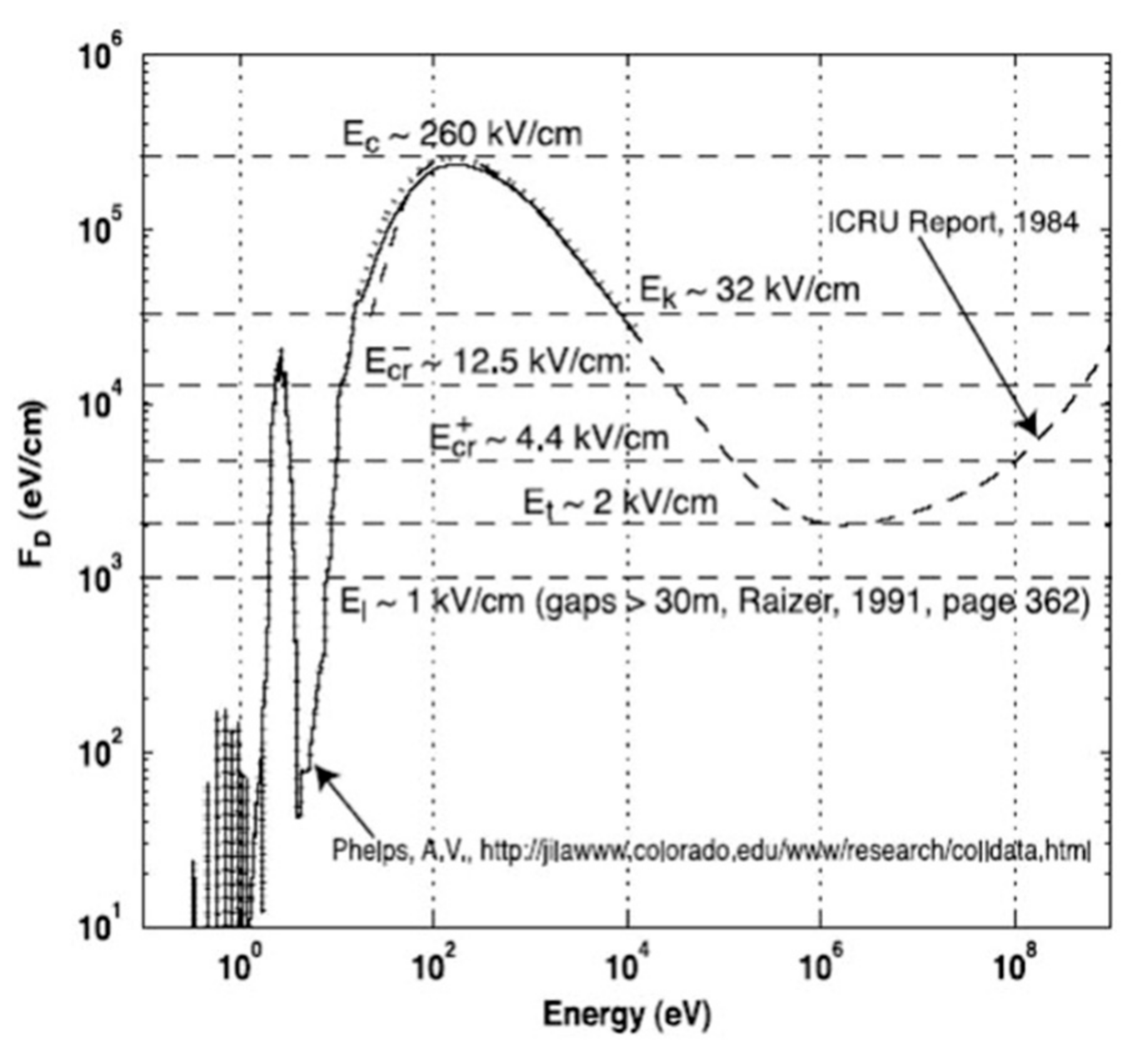
The energy loss curve of electrons in air at atmospheric pressure as a function of electron energy is shown in
Figure 1 [
29]. The energy loss per unit length is given in eV/cm. Note from this curve that, if an electron starts with an energy in the order of a few eV, it cannot increase its energy beyond a few tens of eV if the electric field in air is confined to values of the order of 3 × 10
6 V/m or less, which is the breakdown electric field in air at standard atmospheric pressure and temperature. According to this curve, during electrical breakdown in atmospheric air, the electron energy does not increase beyond about a few tens of eV. However, in order to produce X-rays, the electrons should reach relativistic energies and this cannot happen if the electric field is clamped around 3 × 10
6 V/m during the discharge. As one can observe in
Figure 1, in order to make the cold runaway possible, the electric field at atmospheric pressure has to reach values that exceed about 2.6 × 10
7 V/m [
29]. It is important to mention here that there are higher estimates for the threshold electric field necessary for cold runaway which take into account the finer details, such as electron scattering, of the movement of electrons in the medium [
6,
30]. In the calculations to be presented here, we will use the value stated above but we note that, if the cold runaway threshold is higher, the estimates of the peak energy of the electrons to be given later will be reduced.
There is another way that an electron could reach energies that are capable of generating X-rays. Earth is continuously bombarded by cosmic rays of high energies. When colliding with atoms and molecules, these cosmic rays can eject electrons from these particles with relativistic speeds. If these electrons are located in a background electric field which is large enough so that the energy gain per unit length of travel is larger than the energy loss per unit length (as decided by the energy loss curve shown in
Figure 1), electrons will continue to accelerate, generating more and more relativistic electrons during collisions, leading to an avalanche of relativistic electrons. Consider a cosmic ray generating a 1 MeV electron inside the cloud. In atmospheric air, this electron needs an electric field larger than about 200 kV/m for it to continue accelerating (see
Figure 1). However, since the air density inside the cloud is about half that of ground level, the electron needs about half the value of the electric field needed at atmospheric pressure for it to become a runaway. Thus a 100 kV/m electric field inside the cloud is large enough for the electron to continue accelerating while gaining energy and to become a relativistic runaway. This mechanism is called the ‘hot electron runaway mechanism’. This may give rise to a relativistic avalanche. These relativistic avalanches, when decelerating during collision, can generate X-rays and gamma rays.
It is important to point out that the cold runaway occurs when the electric field is high enough to provide runaway of the electron with any initial kinetic energy and any initial direction of the motion, while the hot runaway occurs only when the initial kinetic energy of the electron is high enough and the initial direction of its motion corresponds to the direction of acceleration.
Since the extent of the background electric field region is large in thunderclouds (hundreds of meters to kilometers), there is ample opportunity for cosmic rays to generate relativistic avalanches inside thunderclouds. Thus, the hot electron runaway mechanism could be active in thunderclouds. On the other hand, in electric sparks including lightning leaders the relevant electric fields are confined to a small region and the chances that this hot runaway mechanism could be active there are very low. The only viable mechanism that could accelerate electrons in laboratory sparks and lightning is the cold runaway mechanism. The various possible mechanisms that can give rise to high electric fields in spark discharges have not yet been exhaustively studied. For example, the existence of high electric fields for very short times, but still capable of accelerating electrons to significant energies during the standard breakdown process, needs further investigations [
31,
32]. Of course, if the electric field increases to values beyond the breakdown electric fields, it does not remain there for very long because the resulting electron avalanches will quench the electric field. In this respect, the possibility of correlated motion of accelerated electrons and high field regions in generating energetic electrons has to be further investigated [
33,
34]. In 2009, Cooray et al. [
35] suggested that the high electric fields necessary for electron acceleration in laboratory sparks are generated during the field enhancements resulting during the collision of opposite streamers. More advanced studies show that even though fields of sufficient magnitudes to accelerate electrons to relativistic energies occur during streamer collisions, the duration of the high field region is insufficient to accelerate copious amounts of electrons in order to generate X-rays comparable to measurements [
36,
37,
38]. On the other hand, Luque [
39] showed that the electrostatic field that penetrates into the streamer channels during collisions could be able to accelerate electrons to relativistic energies. Indeed, more studies are needed to provide conclusive proofs concerning the viability of this mechanism to accelerate electrons to relativistic energies in laboratory sparks. In another paper, Cooray et al. [
40] suggested that the high electric field associated with the tip of dart leaders could accelerate electrons to relativistic energies as this high electric field sweeps along the defunct return stroke channels. The goal of this paper is to show that, in addition to the high electric fields generated during streamer collisions, the ionization waves that result during such encounters are also capable of accelerating electrons to relativistic energies.
2. Hypothesis
Production of X-rays in long laboratory sparks indicates that during these electrical discharges, the electric field exceeds 2.6 × 10⁷ V/m in one or several locations at some instant of time. Here, we provide a possible physical scenario where this can happen. It is important to point out that we are assuming that, during electrical breakdown, cold electron runaway does not occur in regions of the discharge which have elevated temperature and low air density.
As explained below, the mechanism of long sparks involves positive or negative polarity streamers generated from the high voltage electrode and the opposite polarity counter streamers generated by the opposite grounded electrode. Depending on the shape of the applied voltage impulse, the electric breakdown is caused purely by the action of streamers (in lightning impulses) or by a combination of streamers and leaders (in switching impulses).
In the case of lightning impulses, streamers of one polarity travel towards the grounded electrode and, when they come closer to the grounded electrode, the increase in the electric field at the grounded electrode causes it to emit streamers of opposite polarity. At standard atmospheric pressure, the electric field at the head of a single streamer is typically about 10
7 V/m and it decreases to the breakdown electric field of about 3 × 10
6 V/m at a distance of about 200 μm [
41]; the radius of a streamer channel may range from several tens of μm to a few mm [
41,
42]. The meeting of these streamers and the subsequent electrical activity caused by this encounter leads to the breakdown of the gap.
In switching impulses, the streamers from the high voltage electrode will thermalize and heat a common stem, giving rise to a hot leader discharge. The high voltage is transferred along this hot leader channel to its tip, and this gives rise to another streamer burst which, in turn, will thermalize another section of the leader channel, leading to the lengthening of the leader. In this way, the leader approaches the grounded electrode with the aid of streamer bursts. As the leader approaches the grounded electrode, a counter leader, motorized by streamers of opposite polarity which travel towards the down coming leader, is generated by the grounded electrode. The meeting of these two streamer systems leads to the electrical breakdown of the gap.
The experimental data of Kochkin [
27] clearly demonstrate that the physical events associated with the streamer collisions are responsible for the generation of X-rays. The data even show that multiple X-ray bursts are produced by multiple streamer collisions. While the jury on exactly how streamer collisions themselves can give rise to X-rays is still out, here we discuss another physical process which is closely associated with streamer collisions that could accelerate electrons to runaway energies.
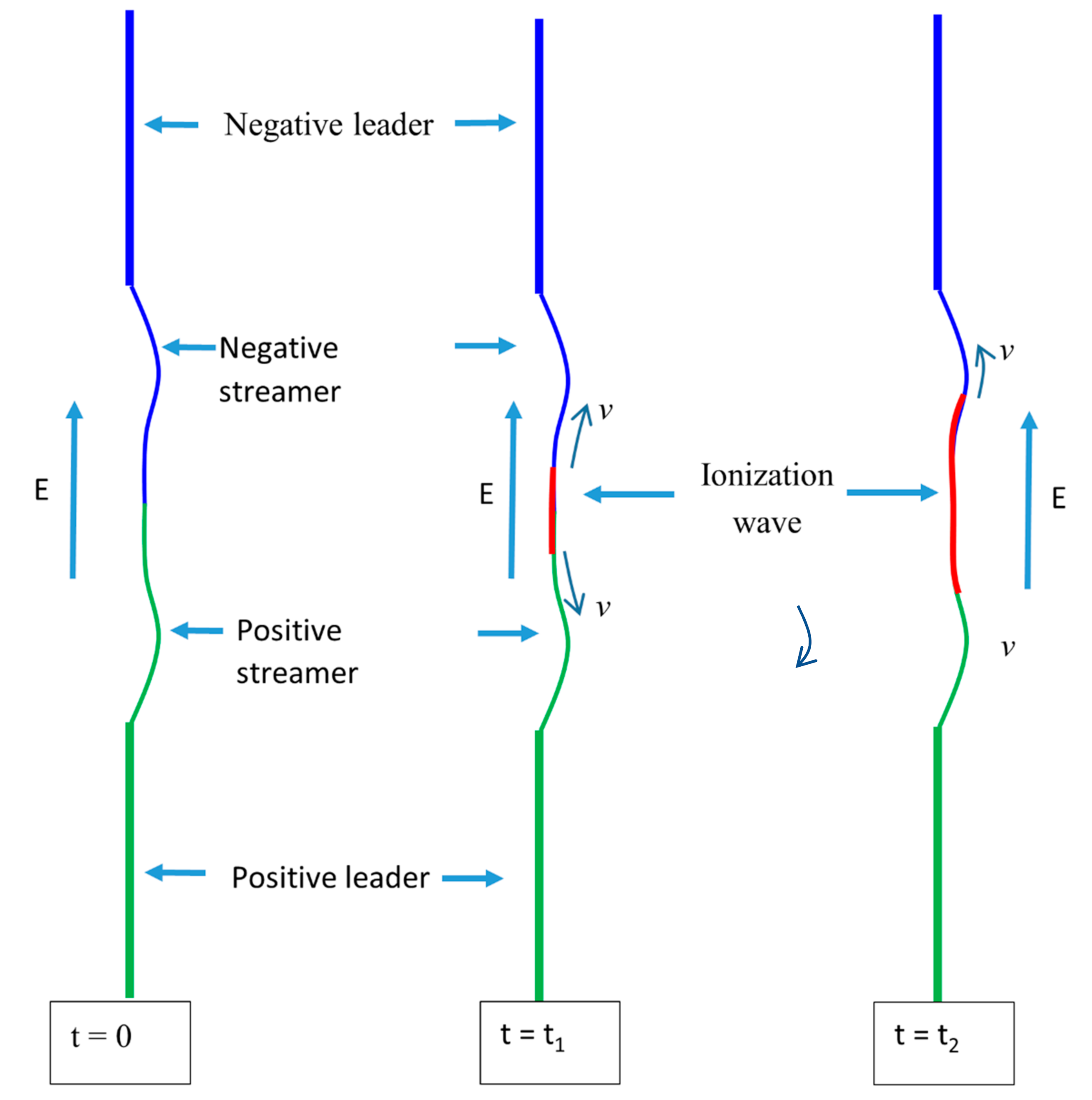
In electrical discharges, whenever two discharge channels of different potentials meet, an ionization wave that attempts to equilibrate the potential will travel along both discharge channels. The return stroke is the best example of an ionization wave or a potential wave that carries the near ground potential along the leader channel [
43]. The presence of a large potential difference at the meeting point of streamer systems of two polarities can be demonstrated easily by appealing to the experimental data of Kochkin [
27]. For example, assume that at the meeting point of the streamers, the length of the positive streamer system is
and that of the negative streamer system is
. The gap length and the applied voltage pertinent to the experiment are such that no significant leader length appears in the discharge at the time of breakdown. Let us denote the potential of the gap at the time of streamer encounter by
. Then, the potential difference
between the two streamer fronts would be
where
and
are the average potential gradients of the streamer channels. Now, in the experiments conducted by Kochkin [
27],
= 1 MV,
= 0.2 m and
= 0.8 m. Assuming
= 10
6 V/m and
= 0.5 × 10
6 V/m, we obtain
= 4 × 10
5 V. Depending on the distance where this potential difference is sustained, there could be a very large electric field at the point of collision of the streamers. This potential difference and the associated high electric field can launch a bidirectional ionization wave that propagates along the streamer systems. These ionization waves carry high electric fields at their tips and cause further ionization along the streamer channels, leading to a path of increased conductivity that bridges the gap, leading to final breakdown. As mentioned earlier, a common example in nature is the return stroke, which is an ionization wave that carries the near ground potential along the leader channel which is at an elevated potential with respect to ground. Another example, associated with the stepping process of stepped leaders, is the meeting of the space leader and the hot stepped leader channel, resulting in a high current pulse that proceeds both along the space leader channel and the stepped leader channel. A dart leader is also an ionization wave caused by the encounter between the defunct return stroke channel and the channel of a K-change, both of which are at different potentials. Experimental evidence also shows that when streamer discharges experience a sudden change in potential, a wave of ionization travels along the streamer channels. For example, experiments conducted in coaxial geometry show that, whenever the potential at the tip of these streamers is suddenly changed by changing the potential of the inner electrode, an ionization wave travels along these streamer channels [
44]. Direct experimental evidence for the creation of ionization waves along streamer channels is provided by the experiments conducted by Suzuki [
45]. In these experiments, physical processes that lead to the transformation of streamer channels into highly conducting discharge channels just before the electrical breakdown are studied using electrical as well as optical observations. Suzuki observed that when the positive streamers from the anode contact the cathode, an ionization wave is propagated along the streamer channel. At low voltages, several ionization waves travelled along the streamer channel before it was thermalized. However, at higher voltages a single ionizing wave becomes capable of thermalizing the streamer channel. The speed of these ionizing waves depends on the voltage applied but the ionizing waves that lead to the final breakdown are propagated at speeds larger than 10
7 m/s. Suzuki [
45] also suggested that the electric field associated with these ionizing waves could be on the order of 2 × 10
7 V/m. Based on the evidence provided by the experiments conducted by Suzuki [
45], we assume that when positive and negative streamers meet, an ionization wave is created and this ionization wave leads to the transformation of the streamer channels into conducting channels that will lead to the breakdown of the gap. As we will show here, such an ionization wave may carry a high electric field at its front that is capable of accelerating electrons on its path to relativistic energies.
4. Results
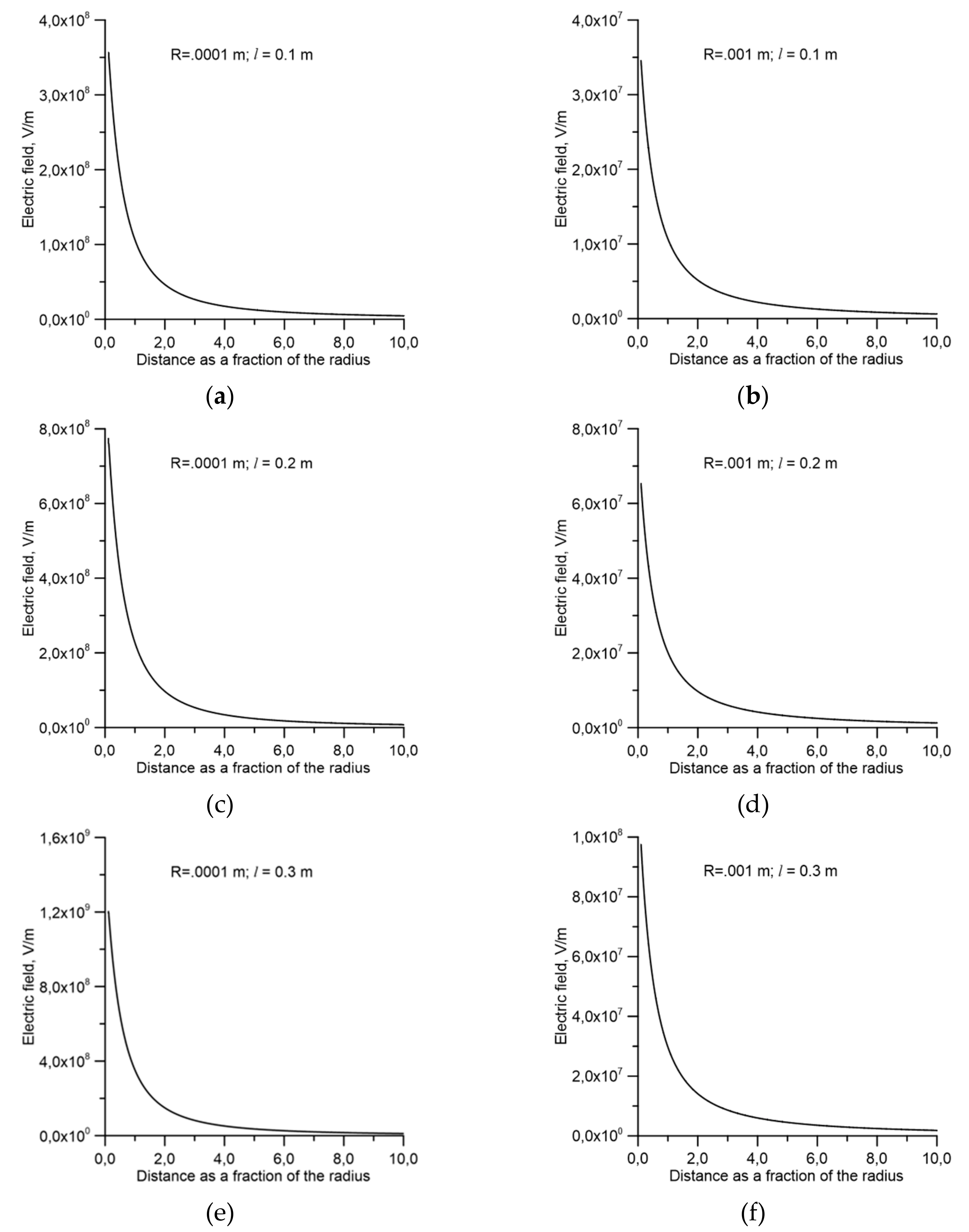
Here, we consider the tip of the ionization wave which is moving towards the positive electrode. In this case, the electrons will be accelerated away from the tip of the ionization wave. As mentioned earlier, even if the peak of the electric field generated by the ionization wave is larger than the threshold electric field necessary to move them into a runaway regime, whether the electrons will be accelerated to relativistic energies will depend on the duration of the high field region. This duration in turn is controlled by the speed of the ionization wave and the speed of the electron. In the analysis, the speed of the ionization wave was fixed at 107 m/s. As the ionization wave proceeds along the channel, all the free electrons located on the path of the ionization wave will be swept over by the electric field. We start our analysis with an electron located at a certain distance from the tip of the ionization wave where the electric field is just at the threshold for cold runaway, i.e., 2.6 × 10⁷ V/m. In the simulation, the energy of the electron is calculated until either it gains enough energy to move beyond the front or until it will be engulfed by the ionization wave.
The parameters that we have studied are the length of the ionization wave, its radius, the background electric field through which the ionization wave is moving and the speed of the ionization wave. As the electrons are exposed to the electric field, they start accelerating and their energy and the speed increases. Initially, the speed starts with a low value and it starts to increase as the electron gains energy from the electric field. As mentioned earlier, the initial position of the electrons coincides with the location where the electric field is equal to 2.6 × 10
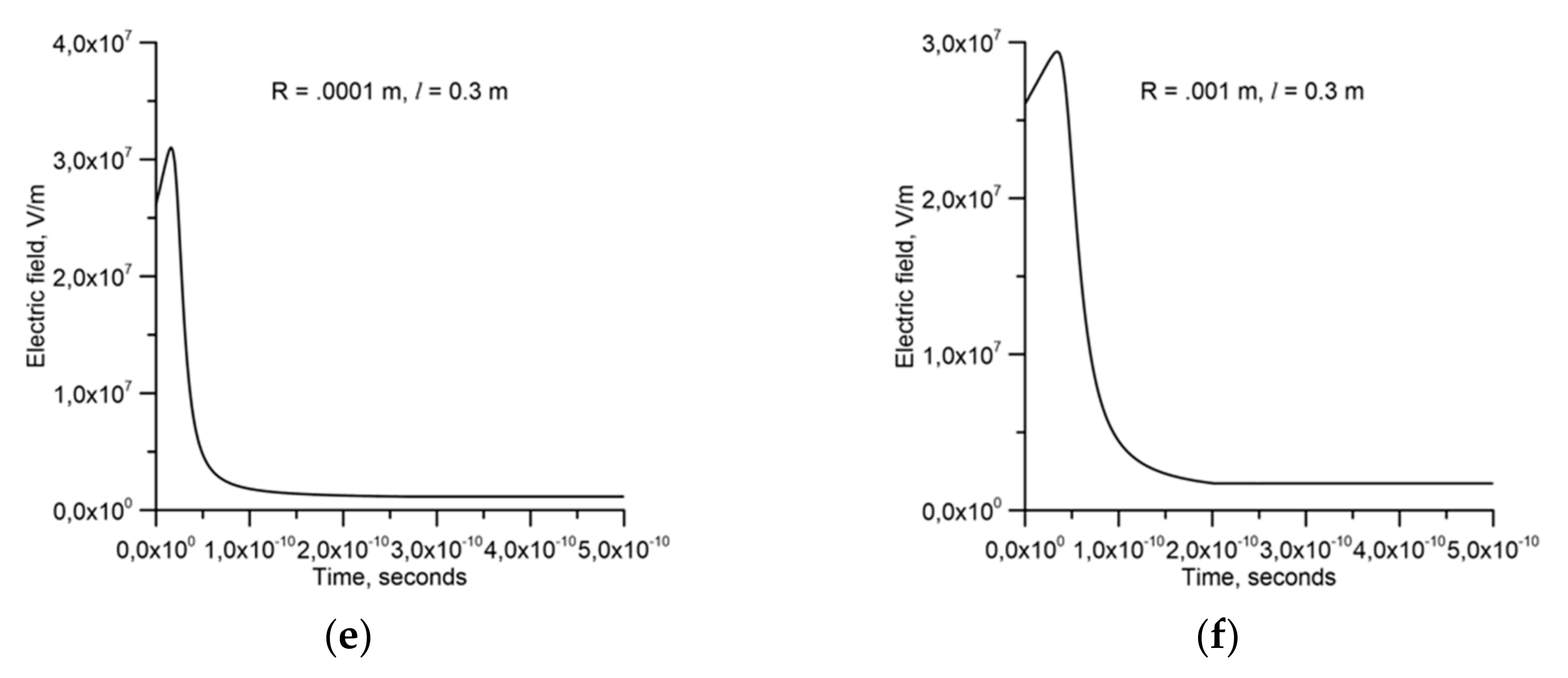
7 V/m. We again remind the reader that here we assume that cold electron runaway does not occur in regions of the discharge with elevated temperature and low density. The electric field experienced by the electron as a function of time is shown in
Figure 4 and the energy of the electron as a function of time is shown in
Figure 5. In each figure, the length of the ionization wave, the radius of the ionization wave and its speed are depicted. In the analysis, three lengths of ionization wave, namely, 0.1, 0.2 0.3 m, and three values of channel radii, namely, 0.0001 and 0.001 m, were used. Recall that the electric field that exists ahead of the ionization wave depends on the length of the ionization wave. During the time when the electron is gaining energy from the electric field, the length of the ionization wave increases continuously and, therefore, the electric field ahead of the ionization wave should also increase and this in principle should be taken into account in the calculation. However, observe that the change in the length of the ionization wave during the acceleration of the electrons is negligible in comparison to the lengths of the ionization waves that we have used in the calculation. Thus, it is justified to use the electric field calculated for a given fixed length of the ionization wave, i.e., 0.1 m, 0.2 m or 0.3 m, to simulate the electric field experienced by the electrons during their interaction with the ionization wave. The results presented in
Figure 4 and
Figure 5 are for a background electric field of 10
6 V/m through which the ionization wave is propagating. In the calculation, the initial energy of the electron is assumed to be 15 eV. However, this parameter does not influence the results presented in the previous graphs.
5. Discussion
Observe in
Figure 4 that, initially, the electric field experienced by the electron increases, reaches a peak and then it starts to decrease. The reason for this is the following. Initially, the electron speed is lower than the speed of the ionization wave and, for this reason, the distance between the electron and the tip of the ionization wave decreases. Since the electric field increases as one moves towards the tip of the ionization wave, the electric field experienced by the electron increases. As the electric field increases, the energy gained and the speed of the electron increase and, at a certain stage, its speed becomes equal to that of the ionization wave. This is the time at which the maximum electric field is experienced by the electron. From that time onwards, the speed of the electron becomes larger than that of the ionization wave and the distance between the electron and the tip of the ionization wave increases. As a result, the electric field experienced by the electron starts to decrease.
The results shown in
Figure 5 clearly show that for a length of the ionization wave on the order of 10 cm or more, the electric field of the ionization wave can accelerate electrons to relativistic energies. In the case of
Figure 5a, when the electron leaves the high field region generated by the ionization wave, it has not gained enough energy to be further accelerated in the background electric field. For this reason it starts losing energy once it has left the high field region of the ionization wave. In all the other cases, the electrons continue to accelerate and gain energy from the background electric field. Observe that the time over which the electrons are accelerated to the relativistic energies is about 5 x 10
−10 s. This is a short time interval but the electric field is large enough during this time interval to accelerate electrons to relativistic energies.
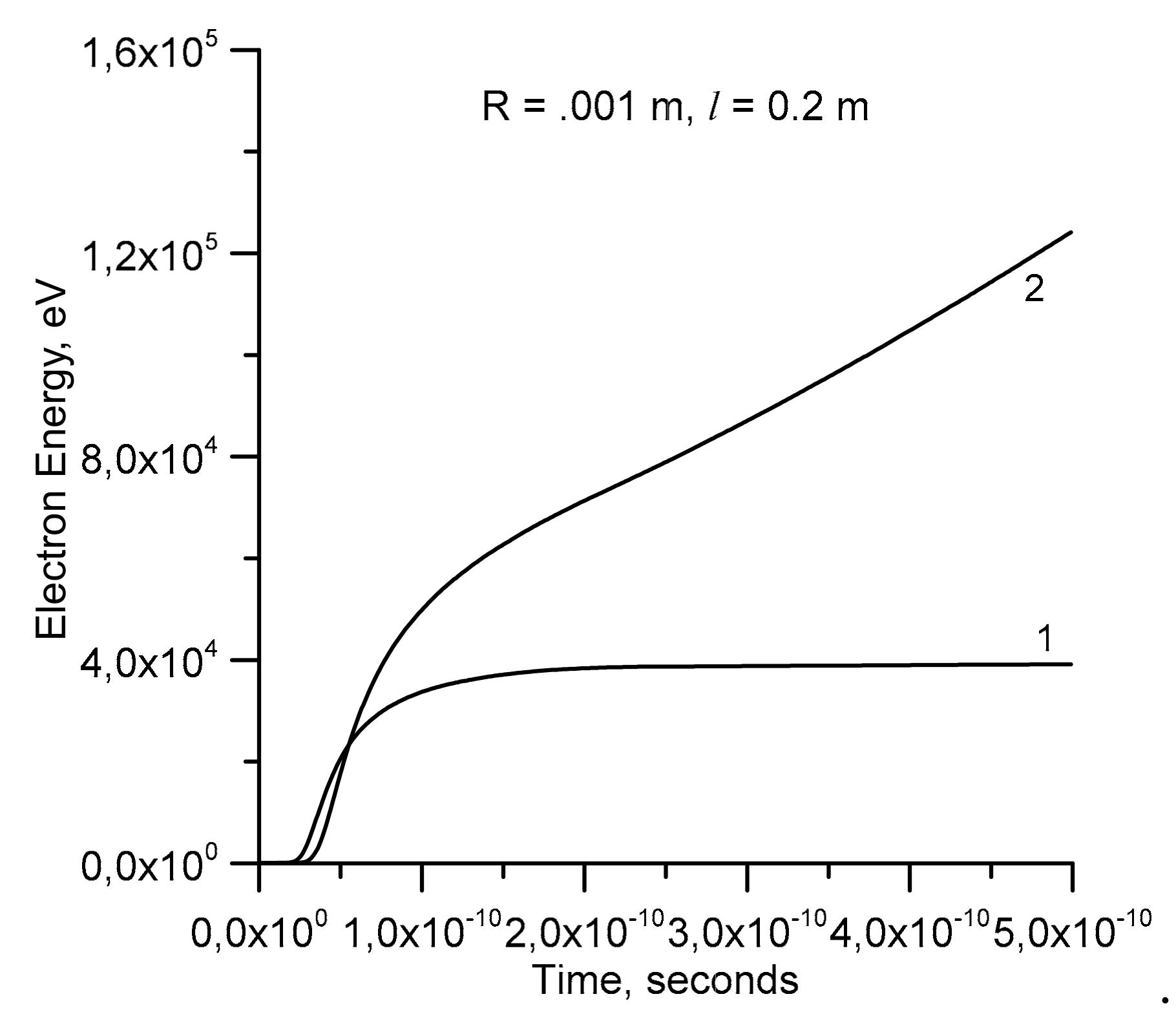
In the results presented in
Figure 4 and
Figure 5, we have assumed that the background electric field to which the conducting region of the ionization wave is exposed is equal to 10
6 V/m. This is approximately equal to the average background electric field in the gap at the time of streamer collision in the experiments conducted by Kochkin [
27]. Of course, the electric field produced by the ionization wave and hence the energy of the runaway electrons depends on the background electric field. It increases with increasing background electric field and vice versa. For example, the energy gained by the electrons when the background electric field is reduced to 0.5 × 10
6 V/m for
= 0.2 m and
= 0.001 m is depicted in
Figure 6 (curve 1). In the same plot, we have depicted the energy gained by electrons when the background electric field is 10
6 V/m (curve 2).
In the calculations presented here, we have assumed that the speed of propagation of the wave is 10
7 m/s. This is based on the measurements of the speed of ionization waves conducted by Suzuki [
45]. Of course, the energy gained by the electrons depends also on the speed of the ionization wave. For example,
Figure 7 shows the effect of the speed of propagation of the ionization wave on the energy gained by the electrons. Observe that the energy gained by the electrons increases as the speed of the ionization wave increases. However, as the speed of the ionization wave increases, there will be a stage where the accelerating electron will be captured by the ionization wave before it had time to escape from the high field region. The curve (marked with a different color) which terminates at the circle in
Figure 7 corresponds to the ionization waves with a speed equal to 3.25 × 10
7 m/s. In this case, the electron was captured by the ionization wave before it had enough time to gain energy to escape from the high field region (the sphere indicates the time and the energy at the time the electron was captured). However, we have to point out that, as mentioned earlier, we have used a static assumption in calculating the field. This is approximately valid as long as the speed of the ionization wave is much smaller than the speed of light. If the front is moving faster, the extension of the field ahead of the front decreases and this leads to a reduction in the length of the region where the high electric field exists ahead of the moving tip of the ionization wave. Unfortunately, calculations of this field for speeds comparable to the speed of light are beyond the scope of this paper.
As mentioned earlier, there is ample evidence in the literature on the creation of ionization waves when electrical discharges of one potential meet another with a different potential. The experimental data presented in reference [
45] and the theoretical studies conducted by Sigmond [
47] provide direct experimental and theoretical evidence for the creation of ionization waves when streamers encounter similar discharges of opposite polarity. In the experiments conducted by Kochkin et al. [
27,
28,
29], almost in time coincidence with the meeting of streamers, one can observe an oscillation of the current in the electrodes. This indicates a sudden injection of charge into the electrodes of the discharge. One reason for these oscillations could be the impingement of the streamers of opposite polarity onto the surface of the electrode. It is also possible that these oscillations are caused by the changes in the current flowing into (or out of) the electrode when it encounters the ionization waves. If this is the case, it will provide indirect evidence for the generation of ionization waves during streamer collisions.
It is important to point out that what we have presented in this paper represents a few time slots of a more or less continuous process. Once initiated, the length of the ionization region increases with time continuously and the different stages that we have described earlier will take place successively. It is also possible that the ionization wave will decay as it propagates forward and it could be re-energized again later due to the accumulation of charges at its ends. Furthermore, streamer collisions could give rise to several ionization waves. Each of these ionization waves could accelerate electrons to energies close to 50–100 keV and the background electric field could accelerate them further to higher energies, resulting in multiple X-ray bursts having energies in the order of several hundreds of keV.
The acceleration of electrons to runaway energies by ionization waves as presented here might raise the question as to why return strokes, being actually an ionization wave, have not yet been observed to generate X-rays. We believe that there are two reasons for this. The first reason could be that the speed of the return stroke is too high for the electrons to be accelerated ahead of the return stroke front and to impart enough energy to electrons to escape the high field region generated by the return stroke without being engulfed by the return stroke. The second, and probably the most important reason, could be the following. The return stroke is propagating along the leader channel which is thermalized. In analyzing the acceleration of electrons to relativistic energies, we consider the situation where electrons collide only with atoms. Thus, the behavior of each electron is determined individually, without being influenced by other electrons. However, in a thermalized channel, electrons are interacting with each other through Coulomb forces. In other words, in this case, the individuality of the electrons disappears and all the electrons act in unison as a single cloud. The energy gained by any electron is shared effectively with other electrons through Coulomb forces. Thus, it becomes much more difficult to accelerate a fraction of the electron population to relativistic energies. These two facts could be the reason for the absence or scarcity of X-ray emissions from return strokes.
