Abstract
Exposure to toxic particles from smoke generated either from bush fire, stable burning, or direct smoking is very harmful to our health. The tiny particles easily penetrate deep into the lungs after exposure and damage the airways. Tobacco smoking causes the direct emission of 2.6 million tons of CO2 and 5.2 million tons of methane annually into the atmosphere. Nevertheless, it is one of the significant contributors to various respiratory diseases leading to lung cancer. These particles’ deposition in the human airway is computed in the present article for refining our understanding of the adverse health effects due to smoke particle inhalation, especially cigarette smoke. Until recently, little work has been reported to account for the transient flow pattern of cigarette smoking. Consideration of transient flow may change the deposition pattern of the particle. A high-resolution CT scan image of the respiratory tract model consisting of the oral cavity, throat, trachea, and first to sixth generations of the lungs helps predict cigarette smoke particle (CSP) deposition. With the same scan, a realistic geometric model of the human airways of an adult subject is used to simulate the transport of air and particle. The CSP deposition is determined at different locations from the oral cavity to the sixth generation of the bronchi. In addition, an unsteady breathing curve indicative of realistic smoking behavior is utilized to represent the breathing conditions accurately. The discrete phase model (DPM) technique is used to determine smoke particle deposition in the human airways. It is found that the deposition increases with the size of the smoke particle. Particles tend to deposit in the oral cavity around the bifurcation junction of the airways. The deposition fraction of CSP with the realistic waveform of smoking is found to be smaller compared to that during the stable flow condition. It is also observed that the fine particles (0.1–1.0 micron) escape to lower generations, leading to higher deposition of fine particles in the deeper airways. The outcome of the study is helpful for understanding smoke-related pulmonary complications.
1. Introduction
Smoke is often considered visible evidence of air pollution, which is a collection of airborne particles and gases. Several sources generate smoke and hence contribute to air pollution, such as stationary sources (thermal power plants, petroleum refineries, factories), mobile sources (all kinds of vehicle that run on fossil fuels), area sources (biomass/stubble/garbage burning, bushfire), natural sources (dust-laden wind, volcanic eruption), tobacco smoking, etc. The significant health hazard that arises from smoke is due to fine particles (0.1–1.0 micron). These tiny micron-sized particles can propagate in the distal regions of the lungs and trigger several diseases from itchy eyes or allergic rhinitis to chronic cardio-pulmonary diseases. Prolonged exposure to such microscopic particles may even cause premature death. Cigarette smoke particles (CSP) have very harmful effects on human airways [1,2]. Tobacco smoking leads directly to the emission of 2.6 million tons of carbon dioxide and about 5.2 million tons of methane [3]. Around 7000 chemicals have been identified in cigarettes and other tobacco products, 250 of which are poisonous and 70 of which are carcinogenic to humans [4], causing mutagenesis of the epithelial cells leading to biologically induced cancers [5]. Globally, smoking remains a leading risk factor for death and disability. Knowledge of CSP deposition is essential in understanding the origin of tobacco-induced cancer [6].
Hinds et al. [7] studied the respiratory deposition of cigarette smoke using a novel measurement system that involved volunteers. The results showed that the smoking style heavily influences the dose of smoke and hence, the deposition pattern in the human respiratory tract (HRT). They also revealed that due to this smoking style, the deposition of cigarette smoke particulate (CSP) in the HRT is often much greater than the deposition of air pollutants during normal inhalation. Martonen [8] investigated the aerosol dynamics of cigarette smoke in a simplified HRT model and revealed that the particle-cloud motion is predominant in the HRT, which is independent of the aerodynamic size characteristics of the smoke particles. This motion is intensified by the vapor-gas phase of the smoke. Subsequently, Phalen [9], Phalen et al. [10], Bernstein [11], Baker and Dixon [12], Gower and Hammond [13], and Kleinstreuer and Feng [14] discussed various aspects of CSP deposition in the HRT viz. the colligative effects of smoke particles, concentrated effects of smoke, retention of tobacco smoke particles, and the effects of ventilated cigarette filters. These researchers had not used the basic HRT model without any physiological intricacies in their experimentation. Many of them had not even considered a realistic smoking pattern while conducting the experiments. Hence, the results of these experiments did not always match the practical data. Of late, more sophisticated measurement techniques, such as differential mobility spectrometry (DMS), are used to collect real-time data on particles and aerosols travelling in the HRT. Mikheev et al. [15] applied DMS coupled with an electrical low-pressure impactor to evaluate the aerosol deposition from an electronic cigarette emission. Puffing topography refers to the behavior of the inhalation of smoke puff by the smoker and it varies with the inhalation time and inhaled volume of puff. The experiment revealed that the puffing topography influenced particle size emitted from the e-cigarette. Li et al. [16] compared the aerosol deposition from the emissions of a conventional cigarette, e-cigarette, and heat-not-burn cigarette using DMS. They found that the total deposition fraction of the aerosol from e-cigarette and heat-not-burn cigarette are higher than the conventional cigarette, while the finer aerosols emitted from the e-cigarette are readily deposited in the HRT.
Multiple path particle dosimetry (MPPD) is a computational model used for calculating the particle deposition in all the airways of the lungs, which is helpful for toxicity risk and drug delivery assessment. Various empirical relationships are used in this computational model to calculate the deposition efficiency of the particles in the lungs [17]. Researchers like Sahu et al. [18] and Sosnowski and Kramek-Romanowska [19] used the MPPD model for cigarette smoke and electronic cigarette smoke particle deposition, respectively. Further, Kane et al. [20] used the MPPD model for finding out the particle deposition from the mainstream cigarette smoke (MCS) that was broadly matched with the smoke retention measurement data when the cloud effect is considered. Asgharian et al. [21], however, stressed the need for accurate input parameters in the MPPD model to ensure accurate predictions. Nevertheless, being a one-dimensional model, the MPPD model cannot predict the deposition concentration zone (hot spots) precisely, and rather indicates general regions like the throat, and tracheobronchial passages [22]. Moreover, the geometrical complexities of the airways in the absence of a realistic HRT scan cannot be included, along with many other factors influencing particle deposition in the lungs in this model [23].
With the progress in the flow computation, the researchers used realistic computational fluid dynamics (CFD) simulation of particle-laden airflow in the CT-scan based HRT model to predict the deposition of particles [24] and viruses [25] in the lungs utilizing arobust numerical scheme. However, the generation of three-dimensional CAD geometry of a whole lung model featuring the morphological details up to distal generation and the subsequent CFD simulation of particle-laden airflow in it is a daunting task in terms of computational power and time involved. CFD simulation still has some advantages over the MPPD model, like intricate lung geometry [26], unsteady and transient flow, turbulence [27], particle dispersion, change of particle size [28], growth of obstacles (lesions/tumors) in the airways [29,30,31], fluid-wall interactions [32], spray, and the atomization of aerosolized drugs [33] can be incorporated, leading to better prediction of airflow and particle deposition in the lungs.
Muller et al. [34] conducted CFD simulation to find out CSP deposition in a Weibel (simplified) lung model up to sixth generation under steady inhalation and exhalation conditions. It was found that the concentration of particle deposition in the central airway surface is independent of inhalation pattern and the airway geometry, indicating that the CSP deposition cannot be significantly reduced by changing the cigarette inhalation pattern. Robinson et al. [35] conducted both experiments and a CFD simulation to investigate the deposition of mainstream and side-stream carcinogenic particles in a realistic tracheobronchial airway up to the sixth generation. The study did not consider the upper airway and imposed idealized boundary conditions at the inlet of the airway. However, the CFD results showed a close match with the experimental one. Steffens [36], on the other hand, used the human airway from oral to third generation and computed the cigarette smoke particle deposition efficiency for various particle sizes on constant puffing and post puffing with timing 1.7 s and 3 s, respectively. It was found that the deposition of small particles ismore likely deeper in the airway, so they concluded that cigarette smoking is very harmful because it contains ultra-fine particles. They also observed that the formation of the laryngeal jet affects the deposition in the trachea due to inertial impaction.
Zhang and his co-researchers worked on size-change [37] and vapor deposition [38] during cigarette smoking in a subject-specific human airway. Most of the CSP deposition was seen in the upper airways with 13–22% deposition fraction between the oral cavity and the larynx and 40–57% in the tracheobronchial airways. Results also showed that vapor deposition was dominated by the puffing behavior as the retention of the smoke in the oral and tracheobronchial cavity was mostly governed by the inhalation waveform. Similar work on CSP deposition in the oral-tracheal airways at various breathing profiles was reported by Li [39], Saber and Heydari [40], and Schroeter et al. [41]. Moreover, Pichelstorfer et al. [42] studied the effect of coagulation and deposition within the HRT and found its impact on CSP deposition. Kolanjiyil and Kleinstreuer [43] conducted a transient particle simulation in a whole-lung airway model (WLAM). They found that a large number of particles are deposited in the alveolar region as compared to the upper airways. Although WLAM can be employed for computing local, regional, and total deposition in toxic and drug particles, the use of WLAM coupled with transient simulation demands excessive memory and computational time. Feng et al. [44] computationally investigated the deposition of smoke particles emitted from electronic cigarettes in an idealized human upper airway geometry from mouth to third-generation using an Euler-Lagrangian method. It was seen that the phase change from liquid to vapor caused hygroscopic growth in the droplets, which considerably affected the deposition concentration of aerosols in the airway. Haghnegahdar et al. [45] used the same Euler-Lagrangian scheme proposed by Feng et al. [44] to compute the deposition and translocation of e-cigarettes and found that the puff volume and the holding time during and after the inhalation of smoke from the e-cigarette are responsible for the enhanced aerosol deposition in the lungs.
Most of the numerical works reported the effects of cigarette smoking on HRT are based on idealized flow conditions of cigarette smoking, which does not depict the actual smoking pattern, which is unsteady in nature. Work on cigarette smoke particle (CSP) deposition in the realistic HRT model is also lacking in the literature. Only a handful of researchers have investigated the effect of puffing waveform on CSP deposition in HRT. However, none have considered inhalation and exhalation together in a single waveform. Variation of puffing time and flow rate are also essential criteria that can alter the CSP deposition in the HRT. Moreover, the possible location of CSP deposition (called ‘hot spot’) that increases the chances of tumor formation in the HRT should also be identified for better diagnosis and prognosis.
Considering the knowledge gaps, we decided to compute the CSP deposition fraction (in percentages) for different particle sizes at constant puffing and post-puffing in a CT scan-based realistic HRT model. The airflow considered through an oral opening resembles the realistic inhalation and exhalation pattern during smoking (called ’realistic puffing’). Under this realistic cigarette puffing pattern, CSP deposition is computed in the HRT. Moreover, the effects of the particle sizes on the CSP deposition are also investigated in the present article.
2. Computational Methodology
2.1. Geometry
Reconstruction of the human respiratory tract (HRT) from CT-scan images are concerned with three significant steps: identification of points of the inner wall of air passage and construction of rings by joining inner wall points using MIMICS software (Materialise, Leuven, Belgium). Next is to align the rings one over another at the distance at which CT slices are taken. Finally, inner wall surfaces are created around the rings. The present study considered a CT-scan-based realistic HRT model from the oral cavity to the sixth generation of bronchi. A CAD model of the same scan was developed in SolidWorks (Dassault Systems, Vélizy-Villacoublay, France) and is shown in Figure 1a. An HRT system consists of the following parts:
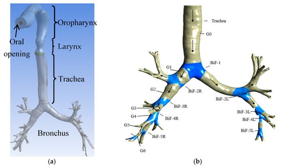
Figure 1.
HRT model from the oral cavity to sixth-generation bronchi with bronchial bifurcations and generations. (a) HRT Model; (b) Bronchial bifurcations (BiF) and Generations (G).
- Oropharynx: This is the rear of the oral opening consisting of a portion of the tongue, soft palate, part of the throat, and the tonsil glands. The opening (inlet) equal to the diameter of a cigarette is provided in the HRT model.
- Larynx: This is known as the ’voice generation box’.
- Trachea: This is known as the windpipe.
- Bronchus: This is one of the two long airways connecting the trachea of the lungs.
The nomenclature of bronchial bifurcations (BiF) and generations (G) are shown in Figure 1b.
2.2. Grid Generation
Figure 2a–c shows the close-up view of the computational grid in different parts of the human respiratory tract model. The division of large computational domains into the small sub-domains is called the mesh or grid. The quality of the mesh is a significant factor for CFD analysis of any computational problem. The mesh should be fine where the flow area is changed and where eddies/turbulence are formed. The quality of the mesh is identified by the skewness; close to zero is better for CFD analysis, but Ansys-Fluent can solve up to 0.95 skewness. The patch-independent method provided in the Ansys-Mesh Modeller (Ansys Inc., Canonsburg, PA, USA) is adopted for grid generation, which uses a top-down approach (i.e., generated mesh from volume to surface). Since the surface of the respiratory tracts is curved, surface meshing is generated using triangular mesh, and volume grid is generated using structured tetrahedral elements. In order to have a high-density mesh at the bifurcations of the HRT model, the edges near the bifurcation have meshed with a layer at a 1:1 growth ratio.
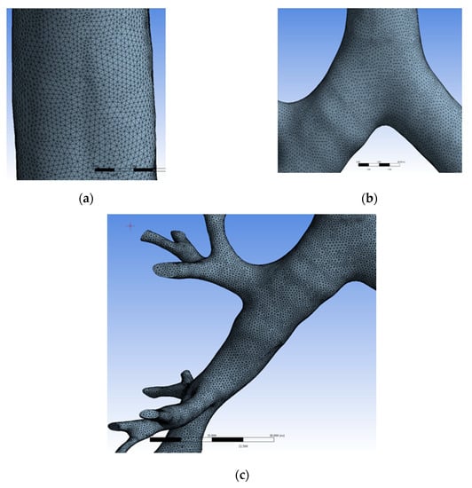
Figure 2.
Computational grid in the HRT model. (a) Close-up view of mesh at the trachea; (b) Close-up view of mesh at the first bifurcation; (c) Close-up view of mesh at bronchus.
The grid independency test (GIT) is the process of selecting the optimum grid size. In CFD analysis, the grid plays an important role. Before proceeding with the simulation, it is necessary to choose the optimum grid size. It can be carried out by calculating the flow phenomenon at different grids determining an increased number of nodes, and mapping the resulting variables like velocity, pressure, and temperature. If the variable is constant to some extent, itis assumed to be the optimum grid. Necessary GIT was carried out as shown in Table 1 for the present meshing scheme, and the solution is found to be grid-independent at 3,536,776 elements.

Table 1.
Grid independency test.
2.3. Governing Equations
CFD works on the fundamental governing equations of fluid mechanics, i.e., continuity, momentum, and energy equations. These equations are the mathematical representation of the flow physics involved in any fluid flow problem.
2.3.1. Continuity Equation
Since the flow during smoking is transient and incompressible, the continuity equation is:
The Momentum Equation is:
where:
- μ = viscosity of fluid
- ui, uj (i, j = 1, 2, 3) is the velocity component in x, y and z direction.
- p = pressure
- ρ = density of fluid.
2.3.2. Governing Equation for Particle Phase
Fluid flow involving cigarette smoke inhalation in the human respiratory tract is a two-phase flow problem in which the governing equation for the gas phase and particle phase are explained separately. In addition to the continuous phase equation, Ansys-Fluent (Ansys Inc., USA) solves the discrete-phase model (DPM) equation for particle trajectory calculation simultaneously. For particle deposition calculation, the DPM equation is used, which is shown as follows.
Particle force balance equation: The force balance equates the particle inertia with forces acting on the particles and is written as
In the above equation, the first term on the right-hand side shows the drag force, and the second term indicate the gravity force on the particle. is defined as follows:
u is the air velocity, up is the particle velocity, μ is the molecular viscosity of air, ρ is the air density, ρp is the density of the particle, and dp is the particle diameter. Re is the relative Reynolds number.
The drag coefficient is calculated as:
where a1, a2, and a3 are constants that apply to smooth spherical particles over several ranges of Reynolds numbers.
2.3.3. LRN k−ω Turbulence Model
The Reynolds number in the human respiratory tract increases up to 522 at the larynx region during the puffing of a cigarette. It is also found that the Reynolds number increases up to 14,500 during inhalation of air. During exhalation, it can, however, increase to 23,285. Hence, turbulence occurs in the human airways during smoking. Solving with continuity and momentum equations, it is also, therefore, necessary to solve the turbulence closure problem associated with the smoking phenomenon.
As the flow in the respiratory tract is of a low Reynolds number, the (LRN) k−ω model is thought to be suitable. It is found that the LRN k−ω model is relatively better for the modeling of laminar-transitional-turbulent airflows in the HRT system [46,47]. Thus, in the present study, the LRN k−ω turbulence model was used to capture the turbulence behavior during puffing and post-puffing of cigarette smoke. The transport equations for k (turbulent kinetic energy) and ω (specific turbulent dissipation rate) in the LRN k−ω turbulence model are described by the following:
are kinetic molecular viscosity, turbulent viscosity, and Reynolds stress tensor, respectively.
and function
with RT = k/µω and µ being dynamic molecular viscosity, model constants are:
2.4. Boundary Conditions
Boundary conditions specify the flow and fluid properties on the computational flow domain for solving any CFD problem. It is a critical component of the CFD solver, and it is important that they must be specified appropriately. Different boundary conditions were chosen for airflow and two-phase flow, which are briefly discussed here.
2.4.1. Airflow Boundary Condition
During smoking, smokers do not inhale the smoke directly into the lungs but instead use the oral cavity as the staging area. When at rest, there is usually little air in the cavity of the mouth, but the smokers can make an air pocket by keeping the lips closed and lowering the jaw and positioning the tongue at the bottom. This allows around 20 cc of air in the oral cavity. After this, either of the two exercises is possible depending upon the liking of the smokers. The first is to start inhalation through the nose that mixes air with the smoke contained in the oral cavity, which subsequently goes down into the lungs. The second option is to inhale air through the mouth, which is generally considered a harsher mode of smoking where only smoke moves down to the lungs in the absence of air mixing. Hence, cigarette smoking is considered a two-step inhalation process. In the first step, a puff of the cigarette smoke is drawn into the mouth. Then, in the second step, smoke is inhaled into the lung along with air inhalation, while some smokers inhale directly into the lung [38].
At the cigarette inlet, the velocity is given by the transient puffing and post puffing waveform, and the equation is described as:
Figure 3 represents inlet air flow rate profile during puffing of the cigarette.
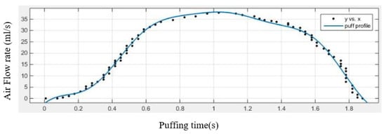
Figure 3.
Inlet flow rate during puffing of cigarette.
The equation forpost-puffing inhalation and exhalation waveform is:
The air flow rate pattern during the inhalation and exhalation phases of the smoking is shown in Figure 4.
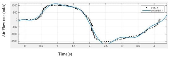
Figure 4.
Inhalation and exhalation flow rate during smoking; [Pattern taken from British American Tobacco (www.bat.com (accessed on 24 June 2021))].
Other airway boundary conditions are shown in Table 2.

Table 2.
Airflow boundary conditions.
2.4.2. DPM Boundary Conditions
The wall of the human respiratory tract is coated with a mucus layer due to the presence of salvia. Therefore, it has a tendency to trap the solid or vapor particle. In order to capture this phenomenon, the discrete phase model (DPM) requires the enabling of boundary conditions like trap, reflect, and escape, as shown in Figure 5.

Figure 5.
DPM wall boundary conditions.
The boundary conditions used for the DPM in the present article are shown in Table 3.

Table 3.
Discrete phase model boundary conditions.
2.5. Smoke Particle Properties
Smoke particle from a cigarette contains 9.4 mg for the reference cigarette 3R4F in the particulate phase [48,49]. In general, a cigarette takes six puffs to generate all the smoke. Hence, the mass flow rate for a single puff is 8.33 × 10⁻⁷ kg/s. The density of smoke particles, according to Lipwicz [50], is taken as 1120 ± 20 kg/m3. Table 4 shows the material properties used for the present study.

Table 4.
Material properties.
2.6. CFD Solver Settings
CFD solver settings used in the present simulation are shown in Table 5.

Table 5.
Solution settings.
3. Results and Discussion
The results obtained by simulating the particle deposition from cigarette smoking in a human respiratory tract (HRT) model are presented in this section in the form of graphs on deposition fraction, variable contours, vectors, and pathlines.
3.1. Deposition and Flow Pattern at Constant Velocity
The following sub-sections discuss the CSP deposition fraction percentage for different particle sizes at constant puffing and post-puffing in a realistic HRT model.
3.1.1. Total Deposition Fraction of CSP at Constant Flow
The deposition of toxic cigarette smoke particulates (CSP) is computed for a variety of particle sizes at a constant flow rate of 2.25 LPM. The value of deposition is shown in Figure 6 in terms of total deposition fraction percentage, and the computed data is compared with the data reported by Steffens [36]. An excellent agreement is observed for particle sizes 1 and 10 µm, while little difference in the deposition fraction percentage is noticed for 5 µm particles. Overall, the present data is validated by the published data.
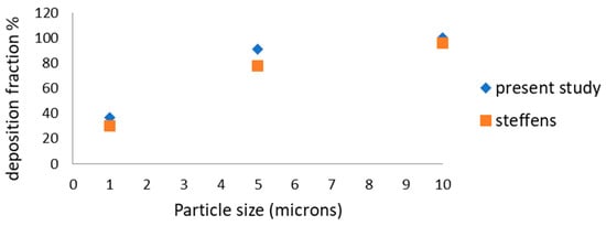
Figure 6.
Total deposition fraction % at constant flow.
3.1.2. Puffing Velocity Contour
In the constant (steady) puffing condition, air velocity at the inlet of the oral cavity should be 0.68 m/s according to a puffing flow rate of 2.25 LPM. No appreciable variation in the velocity contour is seen in Figure 7a. After the puffing (i.e., post-puffing condition), fresh air is inhaled by the smokers, which normally takes place at 30 LPM. Figure 7b shows the velocity variation from the cigarette inlet located at the oral opening to the trachea. A high velocity (~13 m/s) air stream is seen at the oral opening that gradually diffuses as it progresses in the oropharyngeal cavity. However, a relatively high-velocity core exists in the tracheal region, indicative of the influence of fresh air inhalation. A similar pattern was also observed in Steffens [36].
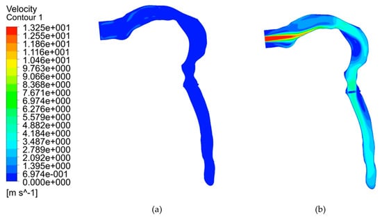
Figure 7.
Velocity contours at (a) constant puffing condition and for (b) fresh air inhalation during post-puffing condition.
3.1.3. Velocity Contours at Transverse Planes at Constant Fresh Air Inhalation
Variation of velocity contour from the oral inlet up to the first bifurcation at constant fresh air inhalation condition is described in Figure 8. A maximum velocity of 13 m/s is observed at the oral inlet as shown in Figure 8a. Velocity is seen decreasing as the area of the airway changes. Diffused velocity contour is observed at the larynx (Figure 8b). Tracheal velocity is reduced further due to the flow diffusion and viscous losses, as evident in Figure 8c. Further, Wall boundary condition fulfils no-slip condition as the contour velocity is zero at the wall. Velocity contour becomes skewed just before the first bifurcation (Figure 8d) with higher velocity in the posterior wall as compared to that of the anterior wall that is attributed to geometrical irregularities and the curvature present in the airways. The skewness of the velocity profile further increases as the flow reaches the first bifurcation (Figure 8e) with the presence of a high-velocity gradient (and hence high shear stress) at both anterior and posterior walls of the airways.
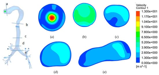
Figure 8.
Velocity contour at transverse planes with constant fresh air inhalation. (a) At oral inlet; (b) At larynx; (c) At trachea; (d) Pre-bifurcation; (e) At first bifurcation.
3.1.4. Generation Wise CSP Deposition at a Constant Flow Rate
The CSP deposition pattern at different generations in the HRT model for various particle sizes at the constant flow rate condition described in the preceding section is shown in Figure 9. The deposition pattern of small-sized particles (1 and 5 µm) is found to be similar at all generations of the HRT. However, the deposition pattern for larger particles (10 µm) is revealed to be different as the inertial impaction is more predominant for larger particles. Hence, larger CSP particles are deposited more at the lower generations (second and third bifurcation regions).
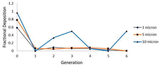
Figure 9.
Generation wise deposition fraction of CSP.
3.2. Results of Realistic Puffing Waveform
Toxic particle-laden airflow (i.e., CSP) is simulated for realistic puffing (inhalation and exhalation) pattern in a CT-scan-based HRT model, and the results are discussed in the following sub-sections.
3.2.1. Velocity Contours at Transient Puffing and Post-Puffing Waveform
In the transient puffing condition, an air-jet of (~1 m/s) is seen developing from the oral inlet, which gradually diffuses as it moves downstream of the airways (Figure 10a). After the puffing (i.e., post-puffing condition), smokers inhale fresh air at around 29 m/s (Figure 10b). Afterward, the velocity of the laryngeal jet stream is reduced and maintained at around to ~6 m/s in the tracheal region, as observed in Figure 10b.
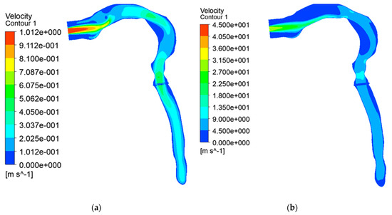
Figure 10.
Velocity contour. (a) Transient puffing; (b) Transient post-puffing inhalation.
3.2.2. Airflow Vector with Realistic Puffing Waveform Showing Inhalation and Exhalation during Smoking
During smoking, fresh air is inhaled after puffing. Subsequently, the lungs exhale the air volume, and the same is shown in Figure 11 at different instants. Here, inhalation takes place up to the t = 1.9 s; after that exhalation starts, it continues until t = 4.18 s as per the waveform. The realistic waveform of inhalation and exhalation shows that the exhalation velocity is higher than the inhalation velocity. Velocity reaches 28 m/s at the time of inhalation (Figure 11b), but during exhalation, the air velocity reaches 44 m/s (arrow showing at the oral opening in Figure 11e). The laryngeal jet is gradually weakened and subsequently disappears due to the decrease in the inhalation velocity. As a result, the break-up of the vortex structure in the form of small eddies is noticed inside the HRT model just before the completion of the exhalation process (Figure 11f).
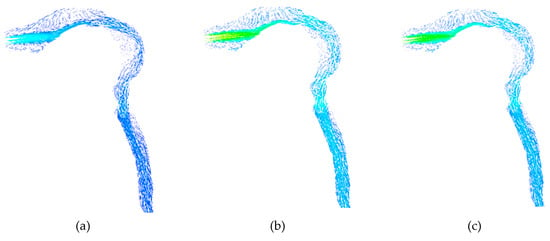
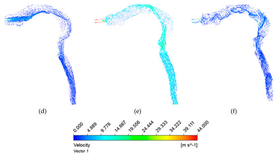
Figure 11.
Airflow vector with realistic puffing waveform showing inhalation and exhalation during smoking. (a) At t = 0.55 s; (b) At t = 1.0 s; (c) At t = 1.5 s; (d) At t = 1.9 s; (e) At t = 2.5 s; (f) At t = 4.1 s.
3.2.3. Velocity Contours at Transverse Planes for Transient Conditions
The streamwise velocity contours at various transverse planes in the HRT model are shown in Figure 12 at different instants. It is noteworthy that the color index for velocity used in Figure 11 is also applicable here. The inhalation phase is maintained up to t = 1.9 s, whereas the exhalation continued until t = 4.1 s. Maximum velocity during exhalation (Figure 12e) is higher than that during the inhalation (Figure 12b).
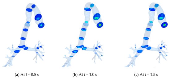
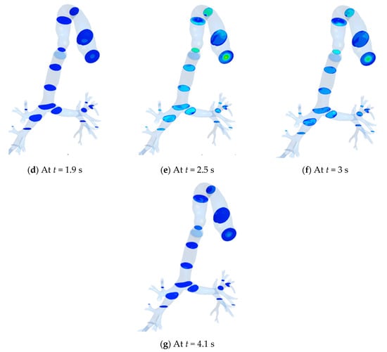
Figure 12.
Velocity contour at different planes with time. (a) At t = 0.5 s; (b) At t = 1.0 s; (c) At t = 1.5 s; (d) At t = 1.9 s; (e) At t = 2.5 s; (f) At t = 3 s; (g) At t = 4.1 s.
As the flow propagates downstream, higher wall shear is experienced near the anterior and posterior walls for both the inhalation and exhalation phases. However, the magnitude of wall shear is found to be higher during the exhalation phase.
3.2.4. Particle Propagation Pattern at Transient Conditions
The propagation of toxic particles from the oral opening to the distal airways of the HRT model during the inhalation phase is shown in Figure 13a–f. The particles are shown here magnified for the sake of visualization to the readers. It is seen from Figure 13a that the inhaled toxic particles (CSP) formed a cone-shaped structure at the onset of smoking cigarettes.
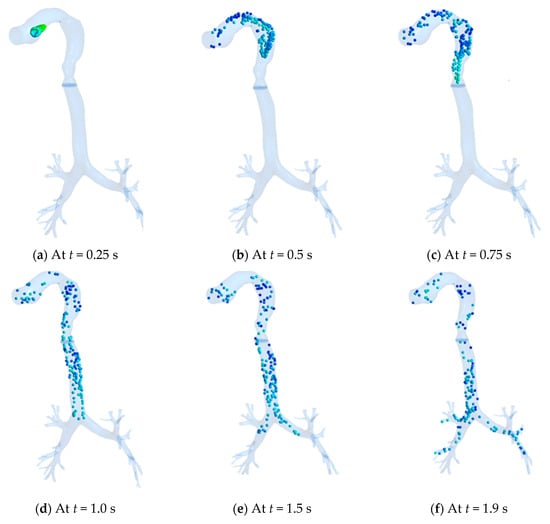
Figure 13.
Propagation of toxic particles in HRT at various instants. (a) At t = 0.25 s; (b) At t = 0.5 s; (c) At t = 0.75 s; (d) At t = 1.0 s; (e) At t = 1.5 s; (f) At t = 1.9 s.
The bolus of particles, however, quickly expands as they enter the oral cavity (Figure 13b), subsequently propagating through the oropharynx (Figure 13c) and reaching the tracheal region (Figure 13d). The particles encounter the first bifurcation (Figure 13e), where many particles are deposited due to inertial impaction and finally moved to the distal region of the airways (Figure 13f). In this process, it is evident from Figure 12a to Figure 12f that the velocity of the particles is seen reducing as it moves downstream due to impaction and viscous losses.
3.3. CSP Deposition at Different HRT Locations with Transient Smoking Waveform
In this section, deposition of cigarette smoke particulate (CSP) is computed for the realistic flow pattern of smoking that is transient in nature. Particle sizes are varied at 0.1 µm, 0.5 µm, and 1 µm to investigate the effect of particle size on the regional deposition pattern in the HRT model at various time instants.
3.3.1. CSP Deposition at Various Locations of the HRT
Figure 14a–e represents the deposition of toxic particles at different locations of the HRT model at different instants during inhalation for various particle sizes. The deposition is expressed in these graphs as deposition fraction (percentage). As the smokers started to inhale, smaller-sized toxic particles (0.1 μm and 0.5 μm) are deposited rapidly in the walls of the oropharynx and achieve a higher deposition fraction as compared to the larger particles (1 μm) due to diffusion. As time elapsed, the trend reversed, and the highest deposition fraction is computed (~37%) for 1 μm particles at the end of the inhalation phase due to inertial impaction.
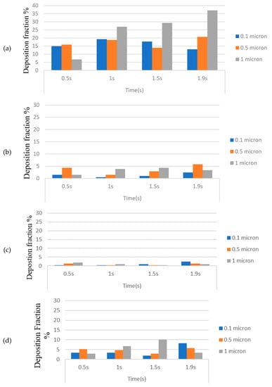
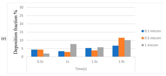
Figure 14.
(a) Smoke particle deposition in the oropharynx; (b) Smoke particle deposition in the trachea; (c) Smoke particle deposition in first-bifurcation junction; (d) Smoke particle deposition in left bronchus; (e) Smoke particle deposition in right bronchus.
The deposition fraction in the trachea during inhalation is, however, found to be less (within 5%) for all particle sizes at all instants (Figure 14b), whereas the least deposition is computed at the first bifurcation (Figure 14c). It is also worth noting that the deposition fraction is higher in the right bronchus (Figure 14d) as compared to the left bronchus (Figure 14e) because of the compression caused in the left bronchus due to the positioning of the heart towards the left.
3.3.2. Generation-Wise CSP Deposition at Various Instants
The deposition fraction of the CSP is computed at various instants during the inhalation phase and is expressed in percentage terms in Figure 15a–d. It is observed from Figure 15a that at the onset of inhalation (t = 0.5 s), deposition fraction for 0.1 μm sized particles is higher at the 0th generation as compared to that for 1 μm sized particles, signifying that the particles are deposited mainly due to diffusion at low velocity. Hence, the effect of inertial impaction is more negligible in the low-velocity range. As the velocity increases with time, deposition for 1 μm particles increased at the 0th generation due to inertial impaction as compared to the diffusion effect.
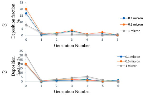
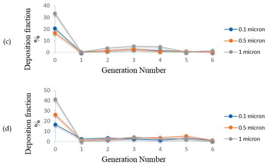
Figure 15.
(a) Deposition fraction of CSP at t = 0.5 s; (b) Deposition fraction of CSP at t = 1.0 s; (c) Deposition fraction of CSP at t = 1.5 s; (d) Deposition fraction of CSP at t = 1.9 s.
3.3.3. Total Deposition Fraction for Different Particle Sizes
It is revealed from Figure 16 that the total deposition fraction percentage of cigarette smoke particles (CSP) is at its maximum for particles sized 1 μm, while it is at its minimum for particles sized 0.1 μm. It can also be seen from the figure that the CSP can be deposited up to 54.8% with a single puff of a cigarette.
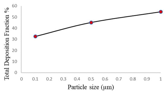
Figure 16.
Total deposition fraction of CSP for various particle sizes.
4. Conclusions
A real smoking pattern with inhalation and exhalation is considered in the present article that furnishes accurate information on the flow physics that occur inside the HRT system during smoking. The deposition fraction percentage of cigarette smoke particle is found less in the realistic waveform as compared to the constant flow rate condition. For particles less than 1 micron, few are deposited in the oral cavity, but they are mostly deposited in the distal lung region. Particle sizes of more than 1 micron are almost all deposited in the oral wall due to inertial impaction and sedimentation. It is also observed that the velocity during exhalation is greater compared to the inhalation velocity for a particular instant during smoking.
In the present study, pressure at the outlet is assumed to be at an atmospheric level (zero gauges), but in the actual case sub-atmospheric pressure occurs at the outlet of the HRT that may affect the flow. This HRT model considered in the current study was up to the sixth generation. Adding a higher generation with an epiglottis to an HRT model would help the researchers to see the fate of the CSP in the distal lung region. Moreover, in the present computation, fresh air was inhaled from the mouth (oral cavity), but many smokers ingest air from the nose during fresh air inhalation. Additional inhalation of fresh air from the nasal opening would dilute the CSP, and hence the immediate physiological effect of smoking could be less fatal. Moreover, variations in puffing, inhalation, and exhalation time may also affect the deposition pattern of CSP. Interested researchers can investigate these aspects in detail. Deposition patterns for less-harmful heat-not-burn tobacco products [51] can also be investigated in the future.
Author Contributions
Methodology, A.R.P. and A.J., Software: F.K. and S.C.S., Validation: F.K. and A.R.P., Formal analysis: A.J. and S.C.S., Investigation: F.K.; Data curation: A.R.P.; Writing—original draft prep-aration: A.R.P. and F.K., Writing—review and editing: A.J. and S.C.S., Project administration: A.J. and A.R.P. All authors have read and agreed to the published version of the manuscript.
Funding
The authors are grateful to the Science and Engineering Research Board (SERB), Govt. of India, for providing the necessary financial assistance with sanction order no. R/S3/MERC/0073/2012 to carry out the research.
Institutional Review Board Statement
Not applicable.
Informed Consent Statement
Not applicable.
Data Availability Statement
The data presented in this study are available on request from the corresponding authors.
Conflicts of Interest
The authors declare no conflict of interest. This article does not contain any studies with human subjects performed by any of the authors.
References
- Centers for Disease Control and Prevention (US); National Center for Chronic Disease Prevention and Health Promotion (US); Office on Smoking and Health (US). How Tobacco Smoke Causes Disease: The Biology and Behavioral Basis for Smoking-Attributable Disease: A Report of the Surgeon General; Centers for Disease Control and Prevention (US): Atlanta, GA, USA, 2010.
- National Center for Chronic Disease Prevention and Health Promotion (US) Office on Smoking and Health. The Health Consequences of Smoking—50 Years of Progress: A Report of the Surgeon General; Centers for Disease Control and Prevention (US): Atlanta, GA, USA, 2014.
- Novotny, T.E.; Bialous, S.A.; Burt, L.; Curtis, C.; Da Costa, V.L.; Iqtidar, S.U.; Liu, Y.; Pujari, S.; D’Espaignet, E.T. The environmental and health impacts of tobacco agriculture, cigarette manufacture and consumption. Bull. World Health Organ. 2015, 93, 877–880. [Google Scholar] [CrossRef]
- Robertson, P.; Walsh, M.; Greene, J. Oral effects of smokeless tobacco use by professional baseball players. Adv. Dent. Res. 1997, 11, 307–312. [Google Scholar] [CrossRef]
- Allam, E.; Zhang, W.; Al-Shibani, N.; Sun, J.; Labban, N.; Song, F.; Windsor, L.J. Effects of cigarette smoke condensate on oral squamous cell carcinoma cells. Arch. Oral Biol. 2011, 56, 1154–1161. [Google Scholar] [CrossRef] [PubMed]
- Robinson, R.J.; Yu, R.J. Deposition of Cigarette Smoke Particles in the Human Respiratory Tract. Aerosol Sci. Technol. 2011, 34, 202–215. [Google Scholar] [CrossRef]
- Hinds, W.; First, M.; Huber, G.; Shea, J. A Method for Measuring Respiratory Deposition of Cigarette Smoke during Smoking. Am. Ind. Hyg. Assoc. J. 1983, 44, 113–118. [Google Scholar] [CrossRef] [PubMed]
- Martonen, T. Deposition patterns of cigarette smoke in human airways. Am. Ind. Hyg. Assoc. J. 1992, 53, 6–18. [Google Scholar] [CrossRef]
- Phalen, R.F.; Oldham, M.J.; Mannix, R.C.; Schum, G.M. Cigarette Smoke Deposition in the Tracheobronchial Tree: Evidence for Colligative Effects. Aerosol Sci. Technol. 1994, 20, 215–226. [Google Scholar] [CrossRef][Green Version]
- Oldham, M.J.; Schum, G.M.; Phalen, R.F. The Deposition of Concentrated Cigarette Smoke in Airway Models. Ann. Occup. Hyg. 2002, 46, 343–345. [Google Scholar] [CrossRef]
- Bernstein, D.M. A Review of the Influence of Particle Size, Puff Volume, and Inhalation Pattern on the Deposition of Cigarette Smoke Particles in the Respiratory Tract. Inhal. Toxicol. 2004, 16, 675–689. [Google Scholar] [CrossRef] [PubMed]
- Baker, R.R.; Dixon, M. The Retention of Tobacco Smoke Constituents in the Human Respiratory Tract. Inhal. Toxicol. 2006, 18, 255–294. [Google Scholar] [CrossRef]
- Gower, S.; Hammond, D. CSP Deposition to the Alveolar Region of the Lung: Implications of Cigarette Design. Risk Anal. 2007, 27, 1519–1533. [Google Scholar] [CrossRef] [PubMed]
- Kleinstreuer, C.; Feng, Y. Lung Deposition Analyses of Inhaled Toxic Aerosols in Conventional and Less Harmful Cigarette Smoke: A Review. Int. J. Environ. Res. Public Health 2013, 10, 4454–4485. [Google Scholar] [CrossRef]
- Mikheev, V.B.; Ivanov, A.; Lucas, E.A.; South, P.L.; Colijn, H.O.; Clark, P.I. Aerosol size distribution measurement of electronic cigarette emissions using combined differential mobility and inertial impaction methods: Smoking machine and puff topography influence. Aerosol Sci. Technol. 2018, 52, 1233–1248. [Google Scholar] [CrossRef] [PubMed]
- Li, Y.; Cui, H.; Chen, L.; Fan, M.; Cai, J.; Guo, J.; Yurteri, C.U.; Si, X.; Liu, S.; Xie, F.; et al. Modeled Respiratory Tract Deposition of Smoke Aerosol from Conventional Cigarettes, Electronic Cigarettes and Heat-not-burn Products. Aerosol Air Qual. Res. 2021, 21, 200241. [Google Scholar] [CrossRef]
- Manojkumar, N.; Srimuruganandam, B.; Nagendra, S.S. Application of multiple-path particle dosimetry model for quantifying age specified deposition of particulate matter in human airway. Ecotoxicol. Environ. Saf. 2019, 168, 241–248. [Google Scholar] [CrossRef]
- Sahu, S.; Tiwari, M.; Bhangare, R.; Pandit, G. Particle Size Distribution of Mainstream and Exhaled Cigarette Smoke and Predictive Deposition in Human Respiratory Tract. Aerosol Air Qual. Res. 2013, 13, 324–332. [Google Scholar] [CrossRef]
- Sosnowski, T.R.; Kramek-Romanowska, K. Predicted Deposition of E-Cigarette Aerosol in the Human Lungs. J. Aerosol Med. Pulm. Drug Deliv. 2016, 29, 299–309. [Google Scholar] [CrossRef]
- Kane, D.B.; Asgharian, B.; Price, O.T.; Rostami, A.; Oldham, M.J. Effect of smoking parameters on the particle size distribution and predicted airway deposition of mainstream cigarette smoke. Inhal. Toxicol. 2010, 22, 199–209. [Google Scholar] [CrossRef]
- Asgharian, B.; Price, O.T.; Yurteri, C.U.; Dickens, C.; McAughey, J. Component-specific, cigarette particle deposition modeling in the human respiratory tract. Inhal. Toxicol. 2013, 26, 36–47. [Google Scholar] [CrossRef] [PubMed]
- Bui, V.K.H.; Moon, J.-Y.; Chae, M.; Park, D.; Lee, Y.-C. Prediction of Aerosol Deposition in the Human Respiratory Tract via Computational Models: A Review with Recent Updates. Atmosphere 2020, 11, 137. [Google Scholar] [CrossRef]
- Tian, G.; Hindle, M.; Lee, S.; Longest, P.W. Validating CFD Predictions of Pharmaceutical Aerosol Deposition with In Vivo Data. Pharm. Res. 2015, 32, 3170–3187. [Google Scholar] [CrossRef] [PubMed]
- Kumar, B.; Srivastav, V.K.; Jain, A.; Paul, A.R. Study of Numerical Schemes for the CFD Simulation of Human Airways. Int. J. Integr. Eng. 2019, 11, 32–40. [Google Scholar]
- Islam, M.S.; Larpruenrudee, P.; Paul, A.R.; Paul, G.; Gemci, T.; Gu, Y.; Saha, S.C. SARS CoV-2 aerosol: How far it can travel to the lower airways? Phys. Fluids 2021, 33, 061903. [Google Scholar] [CrossRef] [PubMed]
- Srivastav, V.K.; Paul, A.R.; Jain, A. Effects of cartilaginous rings on airflow and particle transport through simplified and realistic models of human upper respiratory tracts. Acta Mech. Sin. 2013, 29, 883–892. [Google Scholar] [CrossRef]
- Srivastav, V.K.; Paul, A.R.; Jain, A. Capturing the wall turbulence in CFD simulation of human respiratory tract. Math. Comput. Simul. 2019, 160, 23–38. [Google Scholar] [CrossRef]
- Srivastav, V.K.; Jain, A.; Paul, A.R. Computational Studies of Aerosolized Drug Deposition in Human Respiratory Tract. Recent Adv. Comput. Mech. Simul. 2021, 2, 11–23. [Google Scholar] [CrossRef]
- Srivastav, V.K.; Kumar, A.; Shukla, S.K.; Paul, A.K.; Bhatt, A.D.; Jain, A. Airflow and Aerosol-Drug Delivery in a CT Scan based Human Respiratory Tract with Tumor using CFD. J. Appl. Fluid Mech. 2014, 7, 345–356. [Google Scholar] [CrossRef]
- Srivastav, V.K.; Paul, A.R.; Jain, A. Computational study of drug delivery in tumorous human airways. Int. J. Comput. Sci. Math. 2019, 10, 459–475. [Google Scholar] [CrossRef]
- Singh, D.; Jain, A.; Paul, A.R. Numerical Study on Particle Deposition in Healthy Human Airways and Airways with Glomus Tumor. In Advances in Biomedical Engineering and Technology; Rizvanov, A.A., Singh, B.K., Ganasala, P., Eds.; Springer: Singapore, 2021. [Google Scholar]
- Shukla, R.K.; Srivastav, V.K.; Paul, A.R.; Jain, A. Fluid structure interaction studies of human airways. Sadhana 2020, 45, 1–6. [Google Scholar] [CrossRef]
- Tiwari, A.; Jain, A.; Paul, A.R.; Saha, S.C. Computational evaluation of drug delivery in human respiratory tract under realistic inhalation. Phys. Fluids 2021, 33. [Google Scholar] [CrossRef]
- Muller, W.; Hess, G.; Scherer, P. A Model of Cigarette Smoke Particle Deposition. Am. Ind. Hyg. Assoc. J. 1990, 51, 245–256. [Google Scholar] [CrossRef]
- Robinson, R.J.; Oldham, M.J.; Clinkenbeard, R.E.; Rai, P. Experimental and Numerical Smoke Carcinogen Deposition in a Multi-Generation Human Replica Tracheobronchial Model. Ann. Biomed. Eng. 2006, 34, 373–383. [Google Scholar] [CrossRef]
- Steffens, J. Comparison of Particle Deposition for Realistic Adult and Adolescent Upper Airway Geometries Using Unsteady Computational Fluid Dynamics. Master’s Thesis, Department of Mechanical Engineering, Rochester Institute of Technology, Rochester, NY, USA. Available online: https://scholarworks.rit.edu/theses/7253 (accessed on 24 June 2021).
- Zhang, Z.; Kleinstreuer, C.; Hyun, S. Size-change and deposition of conventional and composite cigarette smoke particles during inhalation in a subject-specific airway model. J. Aerosol Sci. 2012, 46, 34–52. [Google Scholar] [CrossRef]
- Zhang, Z.; Kleinstreuer, C.; Feng, Y. Vapor deposition during cigarette smoke inhalation in a subject-specific human airway model. J. Aerosol Sci. 2012, 53, 40–60. [Google Scholar] [CrossRef]
- Li, Z. Particle Deposition in Oral-tracheal Airway Models with Very Low Inhalation Profiles. J. Bionic Eng. 2012, 9, 252–261. [Google Scholar] [CrossRef]
- Saber, E.M.; Heydari, G. Flow patterns and deposition fraction of particles in the range of 0.1–10 µm at trachea and the first third generations under different breathing conditions. Comput. Biol. Med. 2012, 42, 631–638. [Google Scholar] [CrossRef]
- Schroeter, J.; Asgharian, B.; Price, O.; Yurteri, C.U.; Dickens, C.; McAughey, J. CFD simulations of mainstream cigarette smoke particle growth and deposition in the oral airways. J. Aerosol Med. Pulm. Drug Deliv. 2014, 26. Available online: https://www.bat-science.com/groupms/sites/BAT_B9JBW3.nsf/vwPagesWebLive/DO96KCKX/$FILE/Schroeter-ISAM2013.pdf?openelement (accessed on 24 June 2021).
- Pichelstorfer, L.; Winkler-Heil, R.; Hofmann, W. Lagrangian/Eulerian model of coagulation and deposition of inhaled particles in the human lung. J. Aerosol Sci. 2013, 64, 125–142. [Google Scholar] [CrossRef]
- Kolanjiyil, A.V.; Kleinstreuer, C. Computational analysis of aerosol-dynamics in a human whole-lung airway model. J. Aerosol Sci. 2017, 114, 301–316. [Google Scholar] [CrossRef]
- Feng, Y.; Kleinstreuer, C.; Castro, N.; Rostami, A. Computational transport, phase change and deposition analysis of inhaled multicomponent droplet–vapor mixtures in an idealized human upper lung model. J. Aerosol Sci. 2016, 96, 96–123. [Google Scholar] [CrossRef]
- Haghnegahdar, A.; Feng, Y.; Chen, X.; Lin, J. Computational analysis of deposition and translocation of inhaled nicotine and acrolein in the human body with e-cigarette puffing topographies. Aerosol Sci. Technol. 2018, 52, 483–493. [Google Scholar] [CrossRef]
- Luo, H.; Liu, Y. Modeling the bifurcating flow in a CT-scanned human lung airway. J. Biomech. 2008, 41, 2681–2688. [Google Scholar] [CrossRef]
- Kleinstreuer, C.; Zhang, Z. Airflow and Particle Transport in the Human Respiratory System. Annu. Rev. Fluid Mech. 2010, 42, 301–334. [Google Scholar] [CrossRef]
- Rodgman, A.; Perfetti, T.A. The Chemical Components of Tobacco and Tobacco Smoke; CRC Press, Taylor & Francis Group: Boca Raton, FL, USA, 2009. [Google Scholar]
- Jaccard, G.; Djoko, D.T.; Korneliou, A.; Stabbert, R.; Belushkin, M.; Esposito, M. Mainstream smoke constituents and in vitro toxicity comparative analysis of 3R4F and 1R6F reference cigarettes. Toxicol. Rep. 2019, 6, 222–231. [Google Scholar] [CrossRef] [PubMed]
- Lipowicz, P.J. Determination of cigarette smoke particle density from mass and mobility measurements in a millikan cell. J. Aerosol Sci. 1988, 19, 587–589. [Google Scholar] [CrossRef]
- Boué, S.; Goedertier, D.; Hoeng, J.; Kuczaj, A.; Majeed, S.; Mathis, C.; May, A.; Phillips, B.; Peitsch, M.C.; Radtke, F.; et al. State-of-the-art methods and devices for the generation, exposure, and collection of aerosols from heat-not-burn tobacco products. Toxicol. Res. Appl. 2020, 4. [Google Scholar] [CrossRef]
Publisher’s Note: MDPI stays neutral with regard to jurisdictional claims in published maps and institutional affiliations. |
© 2021 by the authors. Licensee MDPI, Basel, Switzerland. This article is an open access article distributed under the terms and conditions of the Creative Commons Attribution (CC BY) license (https://creativecommons.org/licenses/by/4.0/).