Abstract
Airflow structures within convective systems are important predictors of damaging convective disasters. To automatically recognize different kinds of airflow structures (the convergence, divergence, cyclonic rotation, and anticyclonic rotation) within convective systems, an airflow structure recognition method is proposed, in this paper, based on a regular hexagonal template. On the basis of single Doppler radar data, the template is designed according to the appearance model of airflows in radial velocity maps. The proposed method is able to output types and intensities of airflow structures within convective systems. In addition, the outputs of the proposed method are integrated into a projection map of the airflow field structure types and intensities (PMAFSTI), which is developed in this work to visualize three-dimensional airflow structures within convective cells. The proposed airflow structure automatic recognition method and the PMAFSTI were tested using three typical cases. Results of the tests suggest the following: (1) At different evolution stages of the convective systems, e.g., growth, split, and dissipation, the three-dimensional distribution of the airflow fields within convective systems could be clearly observed through the PMAFSTI and (2) on the basis of recognizing the structures of the airflow field, the complex airflow field, such as a squall line, could be further divided into several small parts making the analysis of convective systems more scientific and elaborate.
1. Introduction
Updrafts and downdrafts in convective systems can form complex and variable airflow fields. The convergence, divergence, cyclonic rotation, and anticyclonic rotation are the four structure types of the airflow field. If two prevailing flows in the atmosphere meet and interact, it is defined as a convergence [1]. The inverse of a convergence is a divergence. A cyclonic rotation [2] is defined as a circulation of winds around a central region of low atmospheric pressure, counterclockwise in the Northern Hemisphere and clockwise in the Southern Hemisphere. An anticyclonic rotation is defined as a circulation of winds around a central region of high atmospheric pressure, clockwise in the Northern Hemisphere and counterclockwise in the Southern Hemisphere.
The types and intensities of these four airflow structures (the convergence, divergence, cyclonic rotation, and anticyclonic rotation) usually have a high correlation with the development and evolution of the convective systems and have significant effects on convective weathers. For example, mesocyclones form as warm core cyclones over land and can lead to tornado formation. Convergences usually cause a mass accumulation that eventually leads to a vertical movement and the formation of clouds and precipitation. Therefore, it is important to recognize these structures of airflow field.
At present, Doppler weather radar is commonly used to observe the airflow field structures. It is a type of radar used to locate precipitation, calculate its motion, and estimate its type (rain, snow, hail, etc.). It is meaningful to design algorithms that automatically recognize airflow structures from Doppler radar radial velocity data. However, this task is difficult because the airflow structures are complex and change over time.
In previous studies, based on single Doppler radar, researchers have developed some algorithms to recognize typical structures of the airflow field, such as mesocyclones [3] and the mid-altitude radial convergence (MARC) [4]. A mesocyclone is a vortex of air within a convective storm, which is localized, approximately 2 to 10 km in diameter within strong thunderstorms [1]. Mesocyclones include anticyclones and cyclones. It has been found that over 90% of the mesocyclones are associated with some severe convective disasters [5]. Researchers have developed some automatic mesocyclone recognition algorithms. For example, Stumpf et al. [6] developed the mesocyclone detection algorithm (MDA). It obtains three-dimensional features by the vertical association of two-dimensional features and, then, determines the development history of mesocyclones by time-dependent analysis of three-dimensional features. Smith et al. [7] proposed the two-dimensional local linear least squares derivative (LLSD) method to estimate the vertical vorticity field. Hou et al. [8] also proposed an automatic mesocyclone recognition method based on the detection of velocity couplets.
MARC is a signature of a strong convergence which occurs between upper rear-to-front inflow (originating from the backside of the storm) and front-to-rear updraft flow (originating ahead of the storm). The intensity of a convergence appears to be related to wind damage [9]. Researchers have also developed some automatic recognition algorithms for MARC. Wang et al. [10] proposed a method based on the recognition of “positive–negative velocity region pairs” in Doppler radar velocity maps to identify the MARC automatically. Wang et al. [11] proposed an automatic MARC recognition method based on the convergence points.
In general, two or more types of airflow field structures can coexist during the evolution of large convective systems (such as squall lines). However, at present, there are no recognition algorithms that can recognize the four structure types simultaneously. The recognition of these four types mainly relies on the experience of meteorologists. The meteorologists infer the three-dimensional structure of the local airflow field from the distributions of positive and negative velocities on radial velocity maps and further determine the weather conditions, however, this work is time consuming and the results are usually subjective. In contrast, if there is an automatic method, it reduces the manual workload and provides more objective assessment results. On the basis of single Doppler radar data, the purpose of our study is to develop an algorithm using computer vision technology to automatically recognize four types of airflow field structures and achieve results similar to those of humans. In order to achieve this purpose, we designed a method based on a regular hexagonal template to automatically recognize convergence, divergence, cyclonic rotation, and anticyclonic rotation.
Our method has several advantages over earlier approaches. First, our method innovatively integrates the four structure types into one recognition template, which can recognize these four structure types at the same time. Secondly, our template recognition is automatic, which can reduce workload and provide more objective results. Third, our template recognition results are presented using a projection map of the airflow field structure types and intensities (PMAFSTI) to visualize three-dimensional airflow structures within each convective system.
The technology proposed in this paper is a supplement to the existing radar products. In fact, the technology proposed in this paper also depends on existing radar products. For example, before applying our technology, a velocity de-aliasing algorithm is required to preprocess the radar radial velocity, because the aliasing velocity causes many false alarms. In addition, the estimated environmental wind velocity (e.g., using the velocity-azimuth display (VAD) algorithm [12]) should be subtracted from the radar velocity field, otherwise, the proposed technology misses some airflow field.
This paper is structured as follows: Section 2 introduces a detailed description of our recognition algorithm of airflow field structures and a PMAFSTI is also proposed. Section 3 presents the case analysis that involves three typical convective weather cases and the discussion of our method. Finally, a conclusion of our work is presented in Section 4.
2. Recognition Algorithm of Airflow Field Structures
2.1. Structure Model of Airflow Field and Template Design
The aim of this work is to design an algorithm to automatically recognize different kinds of airflow fields, including the convergence, divergence, cyclonic rotation, and anticyclonic rotation. Inputs of the algorithm are velocity maps of airflow fields observed via Doppler weather radar.
Doppler weather radar [13], also called weather radar or weather surveillance radar (WSR), is a type of radar used to locate precipitation, calculate its motion, and estimate its type (rain, snow, hail etc.). In addition to the reflectivity factor, it can also obtain radial velocity information of raindrops. As the raindrops are carried by winds, the velocity so detected provides a good estimation of the wind velocity. This velocity is the component of the wind velocity vector along the radar beam direction and is known as “radial velocity”. If the wind at the detection point is moving away from the radar, the radial velocity is positive and is called “outflow velocity”. Conversely, if the wind at the detection point is moving towards the radar, the radial velocity is negative and is called “inflow velocity”.
When airflow fields are observed using Doppler weather radar, their appearances are changed. For example, Figure 1 shows airflow field structures and their appearances on the radial velocity maps of Doppler weather radar. Figure 1 is an adaptation of the Figure 3.27 in [14]. In Figure 1, blue ellipse represents the maximum inflow velocity center, and red ellipse represents the maximum outflow velocity center. The grey and black solid arrows in Figure 1 represent the wind direction, the black dashed arrows represent the radar beams, and the central point of each subgraph represents the center of the airflow field. The radar is located directly below the center of the airflow field.
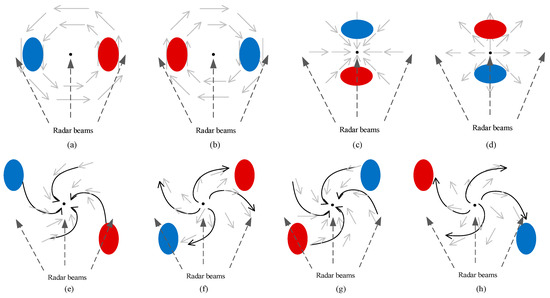
Figure 1.
Velocity structures of the Meso-γ scale system: (a) Pure cyclonic rotation flow field. (b) pure anticyclonic rotation flow field, (c) pure convergence flow field, (d) pure divergence flow field, (e) cyclonic convergence flow field. (f) cyclonic divergence flow field, (g) anticyclonic convergence flow field, and (h) anticyclonic divergence flow field. The central point of each subgraph represents the center of the airflow field and the radar is located directly below the center of the airflow field. Blue ellipses represent the maximum inflow velocity centers, and red ellipses represent the maximum outflow velocity centers. Grey and black solid arrows represent the wind directions and black dashed arrows represent the radar beams.
As shown in Figure 1a, in a small region within the effective detection range of radar, there is a Meso-γ scale [15] rotation. The cyclone appears as a velocity couplet that is composed of a maximum inflow and a maximum outflow. The center of the maximum inflow velocity region is as close to the radar as the outflow one, and the outflow one is on the right side. Figure 1b shows an anticyclonic rotation. The center of the maximum inflow velocity region is on the right side of the center of the airflow field and the outflow one is on the left side. Figure 1c,d shows a radial convergence area and a radial divergence area, respectively. In Figure 1c, the centers of the maximum inflow and outflow velocity regions are in the same radial direction of the radar, and the center of the maximum outflow velocity region is closer to the radar. Conversely, this region is a radial divergence region.
As shown in Figure 1, structure types of the airflow field can be determined by orientation relationships among the radar, the positive and negative velocity extremum regions. Specifically, all kinds of airflow field structures appear as a velocity couplet in Doppler radar radical velocity images. This couplet can be described using three parameters, length (L), orientation (∆θ), and velocity difference (dv). These three parameters are further illustrated in Figure 2. In Figure 2, and are the local maximum and minimum velocity regions of the velocity couplet, respectively. Their geometric centers are and , respectively. Point P is the point at the boundary line between positive and negative velocity regions. A polar coordinate system is established by setting P as the pole and radar beam ray as the pole axis. ∆θ is the polar angle of in this polar coordinate system and , L is the distance between and , and d is the projection of L on the radar beam ray.
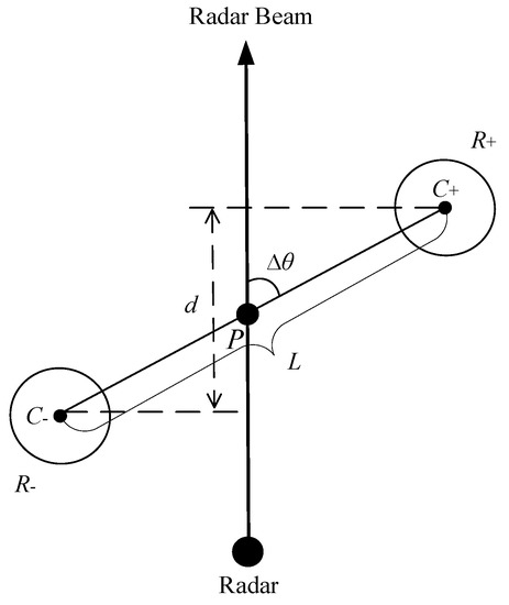
Figure 2.
The velocity couplet to represent the airflow field structure. and are the local maximum and minimum velocity regions of the velocity couplet, respectively. Their geometric centers are and , respectively. Point P is the point at the boundary line between positive and negative velocity regions. A polar coordinate system is established by setting P as the pole and radar beam ray as the pole axis. ∆θ is the polar angle of in this polar coordinate system and , L is the distance between and , and d is the projection of L on the radar beam ray.
Through the three parameters of the velocity couplet, the structure types of the related airflow field such as the convergence, divergence, cyclonic rotation, and anticyclonic rotation can be determined. By combining Figure 1 and Figure 2, we find out that the types of the airflow fields are related to ∆θ of the velocity couplet. The relationships we set are summarized in Table 1. In addition, the distance L between the inflow and outflow velocity extreme points should be less than a given value.

Table 1.
Relationships between airflow field types and ∆θ.
On the basis of the relationships between airflow field structures and velocity couplets, the complex airflow field structures in convective systems could be recognized by recognition of velocity couplets in radar velocity radial maps. For example, a mesocyclone could be identified at the place where the velocity couplets that have an exit. In this work, a regular hexagonal template is designed to recognize four types of airflow field structures. Figure 3 shows the shape of the template. The template is composed of two subtemplates. The first subtemplate is designed as two regular triangles with the same vertex (Regions A and B in Figure 3). It is used to recognize velocity couplets that correspond to convergences or divergences. Similarly, the second subtemplate is designed as two diamonds with a common endpoint (Regions C and D in Figure 3). It is used to recognize velocity couplets that correspond to cyclonic rotations or anticyclonic rotations. By combining the above triangle and diamond subtemplates, a regular hexagonal template for recognizing four types of airflow field structures could be obtained.
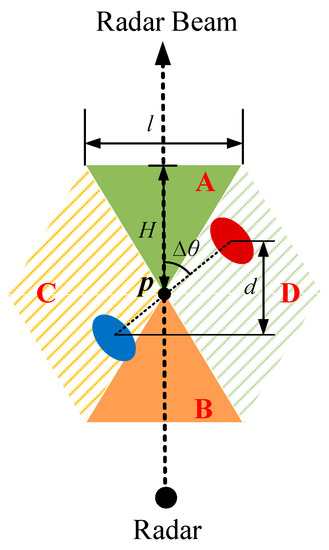
Figure 3.
The regular hexagonal template for airflow field structures recognition. The blue ellipse represents the maximum inflow velocity center, and the red ellipse represents the maximum outflow velocity center. Point P is the point at the boundary line between positive and negative velocity regions. The dashed arrow represents the radar beam, d and ∆θ are the same as in Figure 2, and H and l represent the height and base of the triangular Region A, respectively.
For the designed hexagonal template, the height H of the triangle subtemplate is determined according to the maximum statistical distance (max{d} = 6 km) between positive and negative velocity points. We set H = max{d} = 6 km. As the triangle subtemplate is a regular triangle, .
2.2. Template Recognition Process
2.2.1. Data Preprocessing
In this paper, we use a two-dimensional template to recognize three-dimensional airflow fields. Before using the two-dimensional template, the radar data is preprocessed as described below.
First of all, a velocity-azimuth display (VAD) algorithm [12] is employed to estimate the environmental wind velocities at different heights. Then, the estimated environmental winds are subtracted from the original radar velocity fields to eliminate their influence.
In order to use the two-dimensional recognition template conveniently, the variables, radial distance r and azimuth θ, in polar coordinate system of the radar map, are taken as two mutually perpendicular coordinate axes to form a θ-r rectangular coordinate system. The azimuth θ is taken as the horizontal axis with the resolution of 1° and radial distance r as the vertical axis with the resolution of 1 km. To prevent the airflow field near the azimuth angle of 0° from being truncated in the θ-r rectangular coordinate system, the coordinate system is extended horizontally by 20 degrees, as shown in Figure 4b.
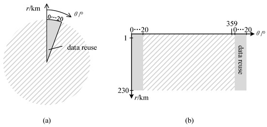
Figure 4.
Conversion from a θ-r polar coordinate system to a θ-r rectangular coordinate system: (a) Circular data region in a θ-r polar coordinate system and (b) rectangular data region in a θ-r rectangular coordinate system. In (b), the azimuth θ is taken as the horizontal axis with the resolution of 1° and radial distance r as the vertical axis with the resolution of 1 km. To prevent the airflow field near the azimuth angle of 0° from being truncated in the θ-r rectangular coordinate system, the coordinate system is extended horizontally by 20 degrees.
Aiming at the severe convection systems, for the rectangular reflectivity data in a θ-r rectangular coordinate system, we only select the storms whose reflectivity is higher than 35 dBZ on the reflectivity maps and whose areas are larger than 150 grids in a θ-r rectangular coordinate system [16]. Their boundaries are extracted and expanded appropriately to obtain the high reflectivity regions at nine elevation angles.
Next, we select the area to be recognized. We project the high reflectivity regions at nine elevation angles horizontally. For these regions, we need to establish vertical matching by calculating the area coincidence degree of projections. If the overlapping area [17] of two projection areas of two high reflectivity regions at two adjacent elevation angles is larger than 60% of the smaller projection area, the two regions are considered to be correlated in the vertical direction and located in the same airflow field, as shown in Figure 5. The minimum bounding rectangle, which we set as a(°) × b(km), of correlated high reflectivity regions’ projections at all elevation angles is taken to determine the position of the air flow field and as the recognition area.
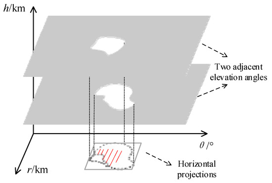
Figure 5.
Determination of the rectangular recognition area, where h is the height from the ground. The high reflectivity regions at different elevation angles are projected horizontally. If the overlapping area of two projection areas at different elevation angles is larger than 60% of the smaller projection area, the two regions are considered to be located in the same airflow field. The minimum bounding rectangle, which we set as a(°) × b(km), of correlated high reflectivity regions’ projections at all elevation angles is taken to determine the position of the airflow field and as the recognition area.
Since we aim to recognize the three-dimensional airflow field, the radial velocity data of the rectangular recognition area at nine elevation angles in a θ-r rectangular coordinate system should be interpolated bi-linearly [18] into m layers’ rectangular data with a height resolution of 0.25 km and a horizontal resolution of (1 km × 1 km). For the place with a horizontal distance of less than 50 km, the maximum elevation of the radar does not detect an altitude of more than 17.5 km. Therefore, we set m = 17.5/0.25 = 70.
2.2.2. Template Recognition
When applying the template in the θ-r rectangular coordinate system, the template needs to be transformed from the polar to the rectangular coordinate system. If the template designed in the θ-r polar coordinate system is used in the θ-r polar coordinate system, the template needs to be rotated as the azimuth changes to ensure that the axis of the template coincides with the radar beam direction, as shown in Figure 6a, which is complex for image processing. While in the θ-r rectangular coordinate system, the direction of the vertical axis and the radar beam direction are the same. Therefore, if the template is used in the θ-r rectangular coordinate system, it does not need to be rotated, as shown in Figure 6b.
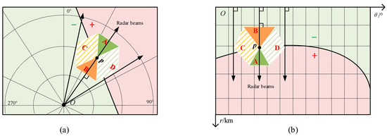
Figure 6.
Template application diagram: (a) Application of the template in a θ-r polar coordinate system and (b) application of the template in a θ-r rectangular coordinate system. In (a) and (b), the green background areas represent the areas with negative radial velocity, while the pink background areas represent the areas with positive radial velocity. The arrows represent the radar beams.
The template is used to recognize airflow structures in the entire flow fields. As the template is designed with the boundary point between the positive and negative velocity regions as the center, the template recognition process is only conducted on boundary points in the radial velocity rectangular maps of 70 layers. Specifically, the template is placed on each point of the boundary line, and the axis of the template coincides with the radar beam, as shown in Figure 6b. The boundary points can be detected using an image segmentation algorithm. All boundary points are recorded as . Using the template, the types and intensities of the two-dimensional airflow field of are calculated as follows:
- Determine airflow directions of the subregions A, B, C, and D covered by the template by counting the numbers of positive and negative radial velocity points in the regions. Take Region A for instance, suppose and are numbers of positive and negative velocity points within Region A, Region A is marked as positive () if > ; otherwise, Region A is marked as negative (). Similarly, airflow directions of Regions B, C, and D are determined.
- Calculation of properties of the regions in the template. Take Region A for instance, if Region A is marked as positive in the previous step, only positive velocity points within this region are used to calculate the properties of the region, including geometric center, average velocity , and maximum velocity . Similarly, if this region is marked as negative, use negative velocity points within this region to calculate the geometric center, average velocity , and minimum velocity .
- Calculation of properties of the region pairs within the template. There are two region pairs in the template, (Region A, Region B) and (Region C, Region D). Take (Region A, Region B) for instance, if Region A and Region B have different directions, i.e., one is positive and the other is negative, the differences between the average velocities of two regions and the maximum velocity difference of two regions are calculated as:The azimuth difference and radial distance difference between the geometric centers of two regions are calculated as illustrated in Figure 2. Conversely, if Region A and Region B have the same direction. All properties are set to zero. Properties of region pairs (Region C, Region D) are calculated using the same method.
- Determine the type of the airflow field and calculate its properties. The airflow structures have the following four types: the convergence, divergence, cyclonic rotation, and anticyclonic rotation. The specific classification rules of the airflow field types are shown in Table 2. After obtaining the results of two subtemplates, we compare and . If , the subtemplate for distinguishing between the convergence and divergence prevails. If , the subtemplate for distinguishing between the cyclonic rotation and anticyclonic rotation prevails. In particular, if , the result depends on the larger one between and .
 Table 2. Classification rules of airflow field structure types.
Once the type of the airflow field is determined, we also calculate its four properties, as shown in Table 3. Finally, the airflow field is described using a five-dimensional feature vector, (p1, p2, p3, p4, p5), where p1 belongs to {1, 2, 3, 4} and denotes the airflow field structure type; 1,2,3,4 denote the convergence, divergence, cyclonic rotation, and anticyclonic rotation, respectively; and p2~p5 record four properties of the airflow field.

Table 3.
Properties of the airflow field.
2.3. Output Visualization
Output of the template recognition process is recorded as a function V (r, θ, h) (h is the height from the ground), where each output of V at the position (r, θ, h) is a five-dimensional vector, (p1, p2, p3, p4, p5). V (r, θ, h) reflects the airflow structure around the boundary point (r, θ, h). To further analyze the airflow structure within a convective cell, the three-dimensional radial velocity region’s recognition results within a convective cell should be obtained.
For a three-dimensional recognition region, i.e., 70 layers’ rectangles, 70 × a(°) × b(km), its corresponding values V (r, θ, h) describe the airflow structures within the detection area. To visualize and analyze these airflow structures, values V (r, θ, h) are projected to two two-dimensional maps, the map of airflow types F1 (θ, h) and the map of maximum velocity differences F2 (θ, h). To obtain F1 (θ, h) and F2 (θ, h), the boundary points that have the maximum velocity differences along r direction are first identified, and their airflow types and maximum velocity differences (regard as intensities) are recorded in two-dimensional maps F1 (θ, h) and F2 (θ, h), respectively. Specifically, for p1(r, θ, h) and p2 (r, θ, h), find rm s.t. p2(rm, θ, h) = , where r is the radial range of the detection area. Then F1 (θ, h) = p1(rm, θ, h) and F2 (θ, h) = p2(rm, θ, h).
Figure 7 shows an example to illustrate how these two maps are achieved. In Figure 7a, the recognition region is marked using a sector box in a polar coordinate system, namely, a rectangular box in the rectangular coordinate system. Figure 7c,b shows the final projection maps of F1 (θ, h) and F2 (θ, h). To make the projection maps clearer, in Figure 7b, the velocity difference values above 20 are discretized with an interval of five, and therefore shallow-to-deep red isolines of this map are present; in Figure 7c, the different structure types are labeled using four colors of yellow (cyclonic rotation), blue (anticyclonic rotation), green (divergence), and grey (convergence). In addition, the two-dimensional maps of the velocity difference isolines and the structure types can be integrated into one map (see Figure 7d), namely the “projection map of the airflow field structure types and intensities” (PMAFSTI).

Figure 7.
Diagrams of the projection map of the airflow field structure types and intensities (PMAFSTI): (a) A radial velocity map at the radar’s elevation angle of 2.3° and (b–d) PMAFSTI. In (b), the airflow field intensities greater than 20 m/s are discretized at intervals of 5 to draw the isolines from light red to dark red. In (c), the different structure types are labeled using four colors and (d) is the superposition of (b) and (c). In (a), a strong rotation structure in radial velocity map is marked by a dashed ellipse, which corresponds to the dashed rectangular areas in (b), (c), and (d).
Obviously, with the help of the PMAFSTI, the three-dimensional spatial structure and intensity distribution of the whole airflow field can be clearly observed. All this information can be used to infer the development stage of the convective cell and furthermore, to forecast the severe convective weathers. Taking Figure 7a for example, there is a strong rotation structure in the radial velocity map at the elevation angle of 2.3° (the dashed ellipse in Figure 7a). This structure is also clear on the PMAFSTI at the same height (the dashed rectangular areas in Figure 7b–d).
3. Cases Analysis and Discussion of Method
3.1. A Squall Line Case in Tianjin, China on 13 June 2005
Taking a squall line [19,20] case in Tianjin on 13 June 2005 as an example, the proposed recognition algorithm of the airflow field structures was tested. The recognition results at 08:29 UTC and 08:54 UTC were analyzed. Figure 8a,d shows the extracted sectors of the high reflectivity regions of the squall line on the reflectivity maps at the elevation angle of 0.5°. Local radial velocity maps at different elevation angles of the corresponding high reflectivity region of the squall line are shown in Figure 8b,e, respectively. The PMAFSTIs are shown in Figure 8c,f. In addition, to visualize the corresponding composite reflectivity maps of the PMAFSTIs, the sector regions of composite reflectivity (the maximum reflectivity from any of the reflectivity angles of the radar) maps were also transformed into the θ-r rectangular coordinate system, which were expanded according to the azimuth angle θ and drawn below the PMAFSTIs, as shown in Figure 8c,f. In this case, the squall line is composed of a group of convective cells. Considering that the reflectivity at the core of the cell is the strongest and the reflectivity weakens outwards, the squall line system at 08:29 UTC and 08:54 UTC could be divided into five micro convective cells. The cells and their corresponding airflow structures are labeled using rectangular boxes in Figure 8c,f, respectively.
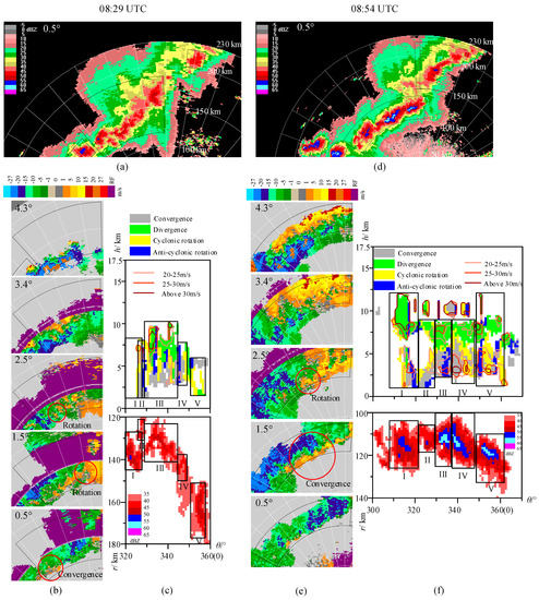
Figure 8.
The airflow field structures of the squall line (13 June 2005) at 08:29 and 08:54 UTC: (a) The reflectivity map at the elevation angle of 0.5° (08:29 UTC), (b) radial velocity maps (08:29 UTC), (c) the PMAFSTI and the corresponding composite reflectivity map in the θ-r rectangular coordinate system of the study region (08:29 UTC), (d) the reflectivity map at the elevation angle of 0.5° (08:54 UTC), (e) radial velocity maps (08:54 UTC), and (f) the PMAFSTI and the corresponding composite reflectivity map in the θ-r rectangular coordinate system of the study region (08:54 UTC).
The local radial velocity maps of the squall line at different elevation angles reveal the three-dimensional airflow field structures of the squall line. At 08:29 UTC, at the elevation angle of 0.5°, there was a relatively weak convergence near the left boundary of the delineated area (the red circular region in the subfigure of 0.5° of Figure 8b); at the elevation angle of 1.5°, the convergence and rotation near the left boundary of the delineated area became stronger, a convergence phenomenon appeared in the middle, and a rotation characteristic was presented on the right side; at the elevation angle of 2.5°, there was a rotation in the left boundary (the red circular region in the subfigure of 2.5° of Figure 8b). In the middle of the sector area, the three-dimensional airflow field structures from low to high elevation angles were convergence (0.5°), rotation (2.5°), and divergence (3.4°), respectively. A weak rotation structure could be seen at the bottom of the right side (the red circular region in the subfigure of 1.5° of Figure 8b).
By synthesizing the information provided by radial velocity maps at different elevation angles, the airflow structures within the squall line can be summarized as follows: (1) The convective airflow field near the left boundary of the selected sector region had matured, showing a structure of the bottom convergence, middle rotation, and upper divergence; (2) there were many rotation pairs of positive and negative velocities in the middle of the selected sector, but they were mainly located in the middle altitude layer. There were no strong convergences in the bottom layer because it was still developing; and (3) the weak rotation dominated near the right boundary of the selected sector region and it was in the early stage of development.
Through the above comprehensive analysis of the radial velocity maps at different elevation angles, we can indirectly understand the airflow field structures of the study region. However, using artificial observation to infer the airflow field within a convective system is inefficient and is limited to qualitative analysis. In contrast, the PMAFSTI (the upper subgraph of Figure 8c) obtained by our method is a more effective analytical tool. It can be used to qualitatively and quantitatively analyze the airflow field structure within a convective system.
Through the PMAFSTI, it is easy to see that near the left boundary of the selected study area, the bottom layer was convergent, and the cyclonic rotation’s height ranged from 1.75 km to 7 km. However, the overall convective intensity was low. In the middle of the study region, there were four pairs of cyclonic and anticyclonic rotations and structures tended to be complete. There was also a strong cyclonic rotation in the low-middle layer and a strong divergence in the upper layer. There was mainly a rotation field with low intensity near the right side of the study region. All this information provided by the PMAFSTI is consistent with the airflow field structure information obtained from the radial velocity maps at different elevation angles.
At 08:54 UTC, 25 min later, the squall line system had further developed. In the composite reflectivity map (Figure 8f), we can see that the reflectivity of the middle and right sides in the squall line had enhanced, while the reflectivity of the left side had weakened. In the radial velocity maps (Figure 8e), there was a strong convergence on the left side at the elevation angle of 0.5°; at the elevation angle of 1.5°, the convergence was obvious and strong, and the range of the convergence was expanded (the red circular region in the subfigure of 1.5° of Figure 8e); at the elevation angle of 2.5°, the convergence coexisted with a rotation (the red circular region in the subfigure of 2.5° of Figure 8e) and; at the elevation angle of 3.4° and 4.3°, the divergence dominated. In addition, in the PMAFSTI (the upper subgraph of Figure 8f), the convective cell I was strong, and its structure was relatively complete. The intensity of the MARC (at the altitude of 3 km) exceeded 25 m/s. Strong airflow pairs consisting of cyclonic and anticyclonic rotations in the middle layer on the right sides were in the development stage. In addition, a strong convergence field with an intensity over 30 m/s was detected in the middle part and the thickness of the part with intensity over 25 m/s was close to 3 km.
The PMAFSTI can be used to infer the airflow structures within convective cells. Table 4 summarizes the characteristics of the identified airflows within the five convective cells at 08:29 UTC and 08:54 UTC, including the airflow type, the intensity, and the height of the airflow. Each column of Table 4 corresponds to a cell. If there are different kinds of airflows within a cell, the corresponding column of the cell is divided into sub-columns. For example, cell II has two sub-columns and three sub-columns at 08:29 UTC and 08:54 UTC, respectively. Each sub-column of cell II records the information of airflow within the cell. As we can see, each cell contains a complex airflow structure.

Table 4.
Five micro convective cells of the squall line (13 June 2005).
By comparing the radar composite reflectivity maps in Figure 8c,f, we can find the squall line system is further developed. The cells at the middle and right sides of the squall line (cells III and IV at 08:29 UTC and the cells III, IV, and V at 08:59 UTC) had enhanced. From Table 4, we find that the airflow structures of these cells revealed by the PMAFSTI are also significantly changed. At 0859 UTC, the intensities of the cells III, IV, and V are larger than that of the cells III and IV at 08:29 UTC; meanwhile, the cyclonic rotational structure become the dominant airflow structure at 08:59 UTC.
From the above analysis of the airflow field recognition results in two moments, the velocity field information of nine elevation angles can be synthesized by our recognition results of the airflow field structures. The qualitative and quantitative structure analysis of the squall line system can also be given. It is intuitive and effective. The development stage of the convective cells can be analyzed by the structure integrities and intensity levels, and therefore we can make effective predictions of the stage. At the same time, the complex structure of the squall line can be clearly displayed. It can be integrated with the cell segmentation algorithms, which makes it possible to segment the micro convective cells from the large convective system, thus, promoting the refinement and scientization of convective weather disaster prediction [21].
3.2. A Local Gale Case in Tianjin, China on 30 July 2015
Taking the local gale in Tianjin on 30 July 2015 as an example, two events of this episode were selected for analysis; one is the event of development and dissipation of a cell (Figure 9) and the other is the event of split of another cell (Figure 10).

Figure 9.
The PMAFSTIs and the corresponding composite reflectivity maps in the θ-r rectangular coordinate system of the event of a cell’s development and dissipation (30 July 2015). Two black dashed lines in the figure connect, respectively, the highest and lowest points of the high-intensity region in the PMAFSTIs of different moments.
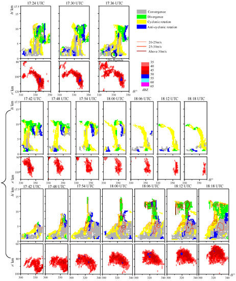
Figure 10.
The PMAFSTIs and the corresponding composite reflectivity maps in the θ-r rectangular coordinate system of the event of another cell’s split (30 July 2015).
The first event is depicted in Figure 9. The cell began to take shape from 15:30 UTC. The whole cell was below an altitude of 10 km. The bottom layer of the cell was convergent, and the middle layer of the cell were cyclonic and anticyclonic rotations. At 15:36 UTC, the airflow intensity, p2, reached above 25 m/s for the first time. Then, the high-intensity region of the cell (the region that has a p2 larger than 20 m/s) gradually expanded upwards and downwards, as shown by the black dashed lines in Figure 9. At 16:30 UTC, the thickness and intensity of the high-intensity region reached the maximum and a region with reflectivity over 55 dBZ appeared in the reflectivity map. At 16:36 UTC, the divergence was detected at the bottom of the cell and a gale was observed at the corresponding position of the divergence (the black circular region in the subfigure of 16:36 in Figure 9). At 16:42 UTC, the thickness of the high-intensity regions began to decrease, and the cell began to dissipate. At 17:06 UTC, the cell collapsed completely.
From the PMAFSTI, the MARC (the gray regions) was dominant in this process. The intensity of the MARC at an altitude of 3 km exceeded 25 m/s for the first time at 16:00 UTC and, then, continued to increase, with the maximum exceeding 30 m/s. The divergence occurred at the bottom 36 min later, resulting in a surface gale at 16:36 UTC. In addition, another predictor of the surface gale was a weak rotation structure included in the main convergence field. At 16:24 UTC, the rotation structure gradually reached the intensity of 25 m/s (the black circular region in the subfigure of 16:24 in Figure 9) and presented a strong horizontal wind shear. After 12 min, when the surface gale appeared, the cyclonic rotation had extended from the altitude of 1 km up to 11 km, with the intensity exceeding 30 m/s. At this time, the cyclonic field dominated.
Figure 10 shows how our algorithm performs on the second event of another cell’s split. At 17:24 UTC, in the cell, a strong cyclonic rotation was detected extending upwards from an altitude of 1 km to 8 km. The intensity of the cyclonic rotation exceeded 20 m/s. At 17:36 UTC, 12 min later, the divergence was detected at the bottom of the cell (the black circular region in the subfigure of 17:36 in Figure 10) and a gale was detected at the corresponding ground station. At the next moment, the cell divided into two parts. In the one part (the sequence of the second row in Figure 10), the bottom layer was divergent, and the middle layer was rotational. The intensity gradually decreased, and the cell dissipated at 18:18 UTC. In the other part (the sequence of the third row in Figure 10), severe convection began to develop upwards and downwards from the rotational part of the middle layer. At 18:00 UTC, a mature convective structure of the bottom convergence, middle rotation, and upper divergence had been formed and the intensity of the MARC within the cell had increased from 20 m/s at 17:42 UTC to 30 m/s at 18:00 UTC. The bottom divergence was detected near the right boundary of the delineated area (the rectangular figure) and the gale was detected at the corresponding ground station at 18:18 UTC.
Through the discussion of the above two events, it is easy to find that the PMAFSTI clearly shows the types and corresponding intensities of the convective system during different stages of growth, development, split, and dissipation of the cell. On the basis of previous observations of mesocyclones, the life history of mesocyclones consists of three stages [22], i.e., the generation stage, the mature stage, and the dissipation stage. The phenomena in these three stages are consistent with the recognition results of the above two events, which proves the validity of our airflow field structure recognition method.
3.3. An Extreme Gale Case in Jianli, China on 1 June 2015
On 1 June 2015, the “Oriental Star” passenger ship was traveling on the Yangtze River in Jianli, Hubei Province, China with 454 people on board when it capsized in a severe thunderstorm, resulting in 442 deaths [23,24]. The recognition algorithm of the airflow field structures was also tested by this extreme gale case. The test results are shown in Figure 11. Two black dashed lines in the figure connect, respectively, the highest and lowest points of the high-intensity region in the PMAFSTIs of different moments. The upper ends of the two-way black arrows point to the highest points of the high-intensity region and the lower ends of the arrows point to the position of the shipwreck. It is easy to see from the black dashed lines in Figure 11 that the thickness of the high-intensity region had gradually increased from 20:23 UTC. At 21:09 UTC, a strong couplet consisting of a cyclonic rotation and an anticyclonic rotation at the altitude of about 8 km appeared (the black rectangular region in the subfigure of 21:09 in Figure 11) and its azimuth was almost the same as that of the shipwreck.
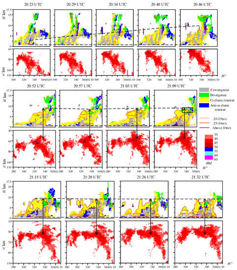
Figure 11.
The PMAFSTIs and the corresponding composite reflectivity maps in the θ-r rectangular coordinate system of the shipwreck (1 June 2015). Two black dashed lines in the figure connect, respectively, the highest and lowest points of the high-intensity region in the PMAFSTIs of different moments. The upper ends of the two-way black arrows point to the highest points of the high-intensity region and the lower ends of the arrows point to the position of the shipwreck.
3.4. Discussion of Method
The proposed algorithm in this work first detects boundary points in the radar radial velocity maps and, then, identifies the airflow types around the points based on a template recognition method. Therefore, the boundary points that are not related with the airflows would lead to many false alarms of our algorithm. For example, when wind blows perpendicular to the radar beams, or reverses its direction by the altitude at high elevation angles, the radar observations have some boundary points without airflows. These false alarms can hardly be distinguished using single Doppler radar. One possible method to solve this problem is to identify airflows using multiple Doppler radars, because these false alarms would change their structures significantly on multiple radar radical velocity maps.
In addition, the performance of the proposed algorithm is highly affected by the environment wind estimation algorithm, such as the VAD algorithm. If the environment wind is estimated incorrectly, the boundary lines of positive and negative velocity points disappear, and thus lead to many misses of airflows. To solve this problem, the environment wind could be set manually before the algorithm is applied.
4. Conclusions
Airflow structures within convective systems are important predictors of damaging convective disasters and useful in recognizing the evolution stage of a convective cell. Automatic recognition of different kinds of airflow structures within convective cells is a challenging task because of their irregular airflow performances and additional noise in the airflow field. In this work, a template-based automatic airflow field recognition algorithm is proposed to identify four kinds of airflow structures in Doppler radar radial velocity maps. The two-dimensional template recognition results are combined to obtain the three-dimensional airflow field structures within convective cells. In addition, a two-dimensional PMAFSTI is developed in this work to visualize the three-dimensional airflow structures of convective cells.
Appearances of four kinds of ideal airflow structures (the convergence, divergence, cyclonic rotation and anticyclonic rotation) in radar radical velocity maps are first analyzed. These typical airflow structures are modeled using a common velocity couplet structure, which is described using three parameters, length (L), orientation (∆θ), and velocity difference (dv). On the basis of the appearance model of velocity couplet, a two-dimensional hexagonal template is designed that has the ability to recognize different kinds of airflow field structures simultaneously. Before using the template, the original Doppler radar data are preprocessed, including coordinates transformation, data interpolation, and determination of potential convective airflow regions of convective cells. After the preprocessing, the original radar data is transformed into grid data of 70 layers. The template recognition process is carried out on each layer to obtain airflow field structures’ types and intensities around boundary points between positive and negative velocities.
Outputs of the two-dimensional template recognition results on different layers compose the three-dimensional airflow structure within each convective cell. In this work, a two-dimensional PMAFSTI is developed to visualize the three-dimensional structures of airflow filed within a cell. The map is obtained by expanding the template recognition results on a θ-h coordinate system and, then, overlapping the map of types and intensities, where the airflow types’ map is represented using four kinds of colors and the airflow intensities’ map is represented using shallow-to-deep red isolines.
The proposed template-based airflow field structures recognition algorithm was tested on three cases of convective disasters. The following conclusions were drawn from these three cases:
- At different evolution stages of the convective systems, for example, growth, split, and dissipation, the three-dimensional structure distributions of the airflow fields within convective systems can be clearly observed by the PMAFSTI, which can be used to support the evolution analysis of the convective system.
- Through recognizing the structures of the airflow field, we can further divide the complex airflow field, such as the squall line, into several small parts, and therefore we can analyze the airflow field changes more concretely and make the analysis of convective evolution more scientific and elaborate.
Author Contributions
All authors have made great contributions to this article. Conceptualization, P.W.; methodology, K.G. and J.H.; software, K.G.; validation, B.D.; formal analysis, P.W.; writing—original draft preparation, K.G.; writing—review and editing, J.H. All authors have read and agreed to the published version of the manuscript.
Funding
This study was partially supported by the Natural Science Foundation of Tianjin, China, under grant no. 14JCYBJC21800.
Acknowledgments
The authors would like to thank the Tianjin Meteorological Observatory for providing radar data and weather-station data.
Conflicts of Interest
The authors declare no conflict of interest.
References
- Glickman, T.S. (Ed.) Glossary of Meteorology, 2nd ed.; American Meteorological Society: Boston, MA, USA, 2000; ISBN 9781878220349. [Google Scholar]
- Reboita, M.; da Rocha, R.; Oliveira, D. Key Features and adverse weather of the named subtropical cyclones over the Southwestern South Atlantic Ocean. Atmosphere 2018, 10, 6. [Google Scholar] [CrossRef]
- Krinitskiy, M.; Verezemskaya, P.; Grashchenkov, K.; Tilinina, N.; Gulev, S.; Lazzara, M. Deep convolutional neural networks capabilities for binary classification of polar mesocyclones in satellite mosaics. Atmosphere 2018, 9, 426. [Google Scholar] [CrossRef]
- Schmocker, G.K.; Przybylinski, R.W.; Lin, Y.J. Forecasting the initial onset of damaging downburst winds associated with a mesoscale convective system (MCS) using the mid-altitude radial convergence (MARC) signature. In Proceedings of the 15th Conference on Weather Analysis and Forecasting, Norfolk, VA, USA, 19–23 August 1996; Volume 15, pp. 306–311. [Google Scholar]
- Trapp, R.J.; Stumpf, G.J.; Manross, K.L. A reassessment of the percentage of tornadic mesocyclones. Weather Forecast 2005, 20, 680–687. [Google Scholar] [CrossRef]
- Stumpf, G.J.; Witt, A.; Mitchell, E.D. The national severe storms laboratory mesocyclone detection algorithm for the WSR-88D. Weather Forecast 1998, 13, 304–326. [Google Scholar] [CrossRef]
- Smith, T.M.; Elmore, K.L. The use of radial velocity derivatives to diagnose rotation and divergence. In Proceedings of the 11th Conference on Aviation, Range, and Aerospace, Hyannis, MA, USA, 4–8 October 2004; pp. 5–6. [Google Scholar]
- Hou, J.; Wang, P. Mesocyclone automatic recognition method based on detection of velocity couplets. J. Tianjin Univ. Sci. Technol. 2017, 11, 64–72. [Google Scholar]
- Nascimento, E.L.; Droegemeier, K.K. Dynamic adjustment in a numerically simulated mesoscale convective system: Impact of the velocity field. J. Atmos. Sci. 2006, 63, 2246–2268. [Google Scholar] [CrossRef][Green Version]
- Wang, P.; Niu, Z. The automatic recognition of Mid-Altitude Radial Convergence and the study of relation between it and strong convective weather based on doppler weather radar data. Physics 2014, 1, 424–436. [Google Scholar]
- Wang, P.; Dou, B. Recognition of strong convergence field based on doppler radar data. J. Tianjin Univ. Sci. Technol. 2018, 8, 797–809. [Google Scholar]
- Tian, L.; Heymsfield, G.M.; Didlake, A.C.; Guimond, S.; Li, L. Velocity–azimuth display analysis of doppler velocity for HIWRAP. J. Appl. Meteor. Clim. 2015, 54, 1792–1808. [Google Scholar] [CrossRef]
- Tang, J.; Matyas, C. A nowcasting model for tropical cyclone precipitation regions based on the TREC motion vector retrieval with a semi-lagrangian scheme for doppler weather radar. Atmosphere 2018, 9, 200. [Google Scholar] [CrossRef]
- Yu, X.; Yao, X.; Xiong, T. Principle and Operational Application of Doppler Weather Radar; China Meteorological Press: Beijing, China, 2006; pp. 60–61. ISBN 750294111. [Google Scholar]
- Wenting, S.; Yuquan, Z.; Fei, W. Case study on the test method of artificial seeding effect for meso-γ scale convective cloud based on radar observation. Meteorol. Environ. Sci. 2017, 2, 11–19. [Google Scholar]
- Dixon, M.; Wiener, G. TITAN: Thunderstorm identification, tracking, analysis, and nowcasting—A radar-based methodology. J. Atmos. Ocean. Technol. 1993, 10, 785–797. [Google Scholar] [CrossRef]
- Juan, S.; Yong, H.; Yan, F. Convective cloud tracking method based on correlation matching and area overlap degree. Comput. Eng. 2011, S1, 336–340. [Google Scholar]
- Gribbon, K.T.; Bailey, D.G. A novel approach to real-time bilinear interpolation. In Proceedings of the Second IEEE International Workshop on Electronic Design, Test and Applications; IEEE: Perth, Australia, 2004; p. 126. [Google Scholar]
- Yeqing, Y.; Xiaoding, Y.U.; Yijun, Z. Analysis on a typical squall line case with doppler weather radar data. Plateau Meteorol. 2008, 27, 373–381. [Google Scholar]
- Mengsong, N.; Liping, Z.; Meifang, Q.U. Study on initialization mechanism and alert of gale in squall line storm event. Meteorol. Mon. 2014, 12, 1491–1499. [Google Scholar]
- Bin, W.; Yangfang, L.; Jie, Q. Severe convective weather automatic identification system based on weather radar data. Meteorol. Hydrol. Marine Instrum. 2014, 4, 33–37. [Google Scholar]
- Watanabe, S.I.I.; Niino, H. Genesis and development mechanisms of a polar mesocyclone over the japan sea. Mon. Weather Rev. 2014, 142, 2248–2270. [Google Scholar] [CrossRef]
- Meng, Z.; Yao, D.; Bai, L.; Zheng, Y.; Xue, M.; Zhang, X.; Zhao, K.; Tian, F.; Wang, M. Wind estimation around the shipwreck of Oriental Star based on field damage surveys and radar observations. Sci. Bull. 2016, 61, 330–337. [Google Scholar] [CrossRef] [PubMed]
- Ni, Z.; Tan, X.; Liu, B.; Ying, Z.; Gao, X.; Yang, F. Rapid risk assessment report for schistosomiasis epidemic in Jianli county caused by the sunk “Oriental Star” cruise ship. Disaster Med. Public Health Prep. 2018, 12, 147–153. [Google Scholar] [CrossRef] [PubMed]
© 2020 by the authors. Licensee MDPI, Basel, Switzerland. This article is an open access article distributed under the terms and conditions of the Creative Commons Attribution (CC BY) license (http://creativecommons.org/licenses/by/4.0/).

