Article

Airborne Wear Particle Emissions Produced during the Dyno Bench Tests with a Slag Containing Semi-Metallic Brake Pads

1
Faculty of Materials Science and Technology, VŠB–Technical University of Ostrava, 70800 Ostrava, Czech Republic
2
Brembo S.p.A, Advanced R&D Department, 24040 Stezzano (BG), Italy
3
Department of Machine Design, KTH Royal Institute of Technology, 10044 Stockholm, Sweden
4
Department of Mechanical Engineering, Lund University, 22100 Lund, Sweden
*
Author to whom correspondence should be addressed.
Atmosphere 2020, 11(11), 1220; https://doi.org/10.3390/atmos11111220
Submission received: 16 October 2020 / Revised: 4 November 2020 / Accepted: 9 November 2020 / Published: 12 November 2020
(This article belongs to the Special Issue Study of Brake Wear Particle Emissions)

Abstract

:
The aim of the present paper is to investigate the level of airborne wear particles released during the dyno-bench tests with the brake pads consisting of alkali-activated slag as an abrasive. Airborne wear particles are generated with a full-scale dyno-bench adapted for airborne wear particles emission studies. The tested disc brake is equipped with two semi-metallic brake pads and a grey cast iron brake disc. A reduced Los Angeles City Traffic (LACT) driving cycle, developed within the LOWBRASYS project (European Union’s Horizon 2020 research and innovation programme), is used to mimic city driving. The same friction pair is used six times with reduced LACT cycle. The weight loss and thickness of the pads and disc are registered after each test cycle ends. The amount of the airborne wear particles emissions released during each test cycle are characterized using a PM10 impactor and electric low-pressure impactor. The obtained data of wear particle emissions are correlated with the parameters of the brake stops. The maximum disc temperature was indicated as the parameter having the largest influence on the production of particle emissions together with the duration of the brake event

Graphical Abstract

1. Introduction

Quality of the air is a significant parameter affecting human health, and thus the sources of air pollution are carefully monitored. One of the major contributors to air pollution is road transportation. The emissions coming from this source are further subdivided into exhaust and non-exhaust emissions. The exhaust emissions originated during the fuel combustion are carefully studied, monitored, and regulated. On the other hand, the non-exhaust emissions [1] (i) originated mainly during the braking of the vehicles [2], (ii) as the results of wear of tires [3], (iii) road wear, and (iv) resuspension of the wear particles deposited in vicinity of the roads, are only studied as yet, although the efforts for their regulation also exist. The comprehensive review dealing with the issue of wear particles produced during the vehicle braking was published by Grigoratos and Martini [2]. Based on this paper, the wear particles originated during braking contributes approximately 21 mass% to total traffic-related particle matter with an aerodynamic diameter smaller 10 µm (PM10) emissions and by 55 mass% to non-exhaust wear particles. With the increase in the number of the vehicles, the contribution of brake emissions to overall air pollution increases.
Most modern cars are equipped with disc brakes which are open to the surroundings. The car disc brake system is designed to decelerate or stop the vehicle by transforming its kinetic energy to heat, whereas the brake pads–brake disc friction couple plays a crucial role in this process. Both pads and disc are worn during braking and contribute to wear particles’ formation. A part of the wear particles sediment to different surfaces, and a part become airborne. In general, there are three laboratory levels on which the airborne wear particles’ generation during the friction process could be tested: (i) pin-on-disc level [4,5,6,7,8], (ii) dyno-bench level [9,10,11,12], and (iii) chase dyno level [13]. The efforts to perform the measurement of airborne wear particles emissions during real road tests also exist [14,15]. The pin-on-discs tests are conducted with the small pins and discs. Both of the friction couples can be extracted directly from real brake pads and brake discs. The typical diameter and height of the pins is 10 mm. What is important in the case of pins and discs is that there is only the effect of the material of the pins and discs, and we could call pin-on-disc tests the test on the “material level”. The tests on the material level are important for the formulation of the friction mixtures and composition of the alloys. On the other hand, the tests with the brake dynamometer and chassis dynamometer are considered as the tests on a system level. In the case of brake dynamometer, real brake disc and brake pads inserted into real brake caliper are used during the test. The tests on chassis dynamometer are conducted with a real car assembled with the friction pair being tested and can be considered as the top level of testing in the laboratory scale. It has to be mentioned that with the growing of the testing level, the time necessary to conduct the tests, the volume of the data necessary to evaluate, and the price of the tests grows as well. So, in a typical chain of the friction formulation or new alloys for brake disc development, the reasonable sequence of the testing procedures is: pin-on-disc tests–dyno-bench tests–chassis tests.
Undoubtedly, the main factors influencing the level of airborne wear particle emissions during the braking is the quality of the friction pair, vehicle parameters (for example its weight), and braking scenario [16]. It was reported that both friction counterparts (pads and disc) contribute almost equally to brake emissions and increasing of their wear resistance is one of the strategies of how to decrease the brake emissions [17]. The review of coatings for the cast iron brake discs was published, for example by Aranke et al. [18]. The effect of the disc rotor treatment using the plasma electrolytic aluminating method on production of particle emissions during the braking with non-asbestos organic (NAO) pads was published by Cai et al. [19]. Regarding the brake pads formulation, Yezhe et al. [8] studied the effect of the copper on the generation of wear particles emissions and observed that the Cu-free friction composite generates more airborne wear particles in comparison to the formulation with copper. Perricone et al. [20] presented the effect of the brake pads formulation and treatment of cast iron brake disc on PM10 emissions released during the dyno-bench test. Dizdar et al. [21] tested grey cast iron brake discs laser-cladded with nickel–tungsten carbide with a pin-on-disc tribometer and concluded that the airborne particle emissions were lower in comparison to uncoated cast iron discs. Wahlström et al. [7] indicated the friction pair containing semi-metallic brake pads with novel kaoline/TiO2 filler and HVOF coated brake disc as promising with respect of reduction of wear particles emissions. Other important parameter affecting the level of brake emissions is the status of the friction pair as reveled Matejka et al. [22]. The authors addressed the effect of new and already used friction pair on the wear particle emissions by repetitive dyno-bench tests of the same friction pair. The study showed significantly lower brake emissions for already used friction pair. Moreover, Wahlström et al. [23] investigated the effect of brake pad scorching and concluded that the level of scorching has an adverse influence on the level of airborne particle emissions.
Friction composites used as brake linings in brake pads are mixtures consisting of materials usually categorized as binders, abrasives, solid lubricants, particulate and fibrous reinforcements, and space fillers [24]. The own formulation of the friction composites designed for automotive brake pads usually consists of more than 20 individual components, and their proper combination is a key factor influencing their performance, durability, as well as comfort properties. The main role of the abrasives is to keep the friction coefficient (COF) at the desired level during braking. Keeping the desired level of COF is possible by renewing the friction surface by its abrasion, so the abraded particles, which could be already thermally altered, are loosed in the form of non-airborne and airborne particles. Several abrasives have already been tested in the friction formulations [25,26]. Not only the type of the used abrasives, but also their particle size, is an important factor affecting the friction-wear performance [27,28].
In general, both natural as well as synthetic materials are tested as the abrasives [29]. The reutilization of the waste materials is an important strategy for sustainable environment and economy. The metallurgy sector produces a great amount of different kinds of by-products and wastes, for example slags, fly ashes, dusts, and sludge. The slag as well as fly ash were already tested as the raw materials in the friction composites formulation [30,31] and both research works showed these by-products as perspective raw materials for friction composites.
The aim of this paper is to report the results of the wear particle emissions originating during the dyno-bench test with the semi-metallic friction composites with alkali-activated granulated blast furnace slag as the abrasive.

2. Experiments

The synthetic abrasive was prepared by alkali activation of granulated blast furnace slag. In this procedure, a milled granulated blast furnace slag (GBFS) (below 100 μm) was mixed with water glass solution with silicate module adjusted to 2. The prepared mixture was poured into the stainless-steel mold (160 × 40 × 40 mm) and vibrated for 2 min. Then, the molds were stored in moist environment with relative humidity 99.9% (RH 99.9%) for 24 h; after this period, the compacted blocks were unmolded and further stored for 28 days in moist environment (RH 99.9%). After this period, the hardened samples were crushed, dried for 24 h at 100 °C in a laboratory oven, and subsequently milled to powder particles with size below 100 μm. The obtained powder sample was used as the abrasive in friction formulation of semi-metallic brake pads. The brake pads were prepared by the hot-press molding method and the weight of both pads together was 820 g. The chemical composition was analyzed using wave dispersive X-ray fluorescence spectroscopy (Rigaku ZSX Primus IV, Japan) using the fundamental parameters method and is shown in Table 1. A cast iron disc was used as a rotor in the experiments and the chemical composition of the cast iron brake disc is shown in Table 2. The weight of the used cast iron disc was 6.6 kg. The chemical composition of the cast iron disc was obtained from the data sheet for these commercially available brake discs.
The set-up of the dyno-bench dedicated for wear particles emission studies was introduced in previous papers published by Perricone et al. [9,12]. The full-scale dyno-bench (TecSA s.r.l., Milan, Italy) was equipped with a closed chamber of the volume 0.817 m3 designed to protect the disc brakes from the surrounding air. The HEPA air was blown inside the chamber with a flow rate of 1175 m3∙h−1 during the whole test. The chamber was designed to enable the isokinetic sampling of the air in a bypass tube, while the flow rate was adjusted to obtain a stream velocity of 3.47 m∙s−1 inside the tube. The disc temperature was measured using the thermocouple embedded in the cast iron disc. Prior to each of the repetitions, the dust box was gently but precisely cleaned to remove the settled and deposited particles. Each of the repetitions included the “cleaning block”, during which HEPA air is blown through the chamber. During this block, the PM10 collection was turned off. The level of particle number concentration (PN) was checked continuously during the “cleaning block” and the values of PN concentration after this block typically oscillated around 100 × 1 cm−3.
The used three hours long LACT procedure (3h-LACT), defined by Marcel Mathissen within the project LOWBRASYS and further introduced in Reference [32], consists of 217 brake events selected to simulate real driving conditions. Used 3h-LACT testing cycle was running 6 times and respective repetitions are labeled as follow Xx3h-LACT (where X = 1 … 6, addressing the number of the repetition of 3h-LACT, thus the meaning of the label 1x3h-LACT is: the first repetition of 3 hours long LACT cycle). The initial and final velocities, deceleration, and initial temperature of each of the brake events are shown in Figure 1.
The disc temperature was registered using an embedded thermocouple. The 3h-LACT procedure was repeated 6 times for the tested friction pair without disassembling after the individual repetition. After the sixth repetition, the weight of the disc as well as both brake pads was measured.
The PM10 particles were collected using 47 mm quartz filter placed in a stainless-steel aerosol filter holder (Millipore). Prior to the filter holder, a cyclone (Dekati) was used to separate the particles bigger than 10 μm. The counting of the particles with diameter in the interval 0.006–10 μm was performed with an electric low-pressure impactor (ELPI+) (Dekati). Both PM10 collection on quartz filter as well as counting of the particles with ELPI+ was done at a flow rate of 10 l⋅min−1, and regarding the HEPA air flow rate through the dust chamber, the volume fraction of sampled aerosol was 0.051%. The PM10 collection as well as particle numbers counting was performed individually for each of the 3h-LACT repetitions.

3. Results and Discussion

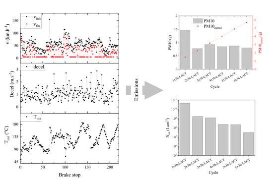
3.1. The Friction Performance

Comparison of the average values of the friction coefficient (COF) and maximum disc temperature measured for the first and sixth repetition of the 3h-LACT procedure is shown in Figure 2. Average COF values ranged in the interval 0.31–0.58 for the 1x3h-LACT and 0.32–0.52 for the 6x3h-LACT. The interval of COF values is narrower for 6x3h-LACT, which indicates smoother character of the friction surfaces of both brake pads and brake disc during this test because of previous repetitions. Obviously higher COFavg values obtained for some of the brake events during 1x3h-LACT (e.g., 41–59, see Figure 2) are related to more abrasive character of the friction contact due to higher surface roughness of both friction counterparts. Subsequent repetitions had the “polishing” effect on the pads´ and disc´s friction surfaces, which is reflected in lower COFavg values obtained for 6x3h-LACT.
The data pictured in Figure 2 showed that there is no significant difference in the registered temperatures within the first and sixth 3h-LACT repetition, except the brake stop numbers 65 and 98. The brake stop 65 is defined by the initial temperature (Tinit) 87 °C, initial and final velocity (vinit, vfin) 154 and 36 km∙h−1, and deceleration (decel) 0.45 m∙s−2. The brake event 98 is defined by Tinit 137 °C, vinit and vfin 114 and 92 km∙h−1, and deceleration 1.43 m∙s−2. The defined initial conditions of both brake events are different. The brake event 65 begins from the highest velocity within all of the brake stops defined in the 3h-LACT cycle and finishes at relatively low velocity, 36 km∙h−1, and to achieve the desired decrease in the velocity, relatively low deceleration is used. All these circumstances led to the fact that the brake stop 65 is the longest one with the duration of almost 64 s. So, long contact of both friction counterparts led to a rise in the temperature to 195 °C, which is the third highest temperature registered within both 1x3h-LACT and 6x3h-LACT. On the other hand, the vinit and vfin of the brake stop 98 are 114 and 92 km∙h−1 respectively, and deceleration is 1.43 m∙s−2, and the duration of this brake stop was approximately 4 s. The maximum disc temperature during brake event 98 was 177 °C. The parameters indicate the brake event 65 as a light brake, while the brake event 98 was an aggressive one. The highest temperature, 207 °C, was achieved for the brake stop 138, which is defined by Tinit 187 °C, vinit and vfin 60.8 and 5 km∙h−1, and deceleration 1.46 m∙s−2, and this brake stop can also be categorized as the aggressive one.
The differences between the maximum temperatures registered during 1x3h-LACT and 6x3h-LACT for brake stops 65 and 98 are probably caused by the differences in the friction surface of the brake pads and disc. It is assumed that the friction surface of both the pads and the disc after the sixth repetition of 3h-LACT is smoother than the friction surface of these friction counterparts originated during the first repetition of the 3h-LACT test. Smoother friction surface means fewer asperities at the surface, resulting in less abrasive character of the friction contact. This fact was reflected also with lower COFavg values obtained for both 65 and 98 brake events during 6x3h-LACT in comparison to these values obtained for the same brake events during 1x3h-LACT repetition (65: 0.453 vs. 0.360; 98: 0.366 vs. 0.361). Smoother surface means higher generation of frictional heat, which is reflected in the higher value of Tmax for 6x3h-LACT registered. Unfortunately, this hypothesis is not true for the other brake events, as evident in Figure 2. Formation of the friction surface is a dynamic and complex process dependent on all of the parameters of a given brake event, including, for example, the initial status of the friction surface affected by the previous brake event or the acceleration before the brake event necessary to reach its initial velocity.

3.2. Relation between the Wear of the Friction Counterparts, PM10 Emissions, and Particle Number Concetration

The weight change of both pads and brake disc after 6x3h-LACT was 6.01 and 5.48 g respectively, and thus the total weight loss of the friction pair reached 11.49 g. The particle number concentration was registered continuously during the whole testing cycle. The PM10 emissions were captured individually for each of the testing cycles using the quartz filter. After, the weight of the captured PM10 emissions was obtained. Knowing the fraction of the air sampling in the bypass sampling tube and the total volume of the HEPA air blown into the chamber during the individual tests, the captured amount of PM10 values were recalculated to the total PM10 emissions originated during these tests, and the values are shown in Figure 3.
The data presented in Figure 3 indicates the first repetition of the 3h-LACT testing cycle as the cycle with the highest PM10 emissions. Further repetitions produced almost 50% less PM10 emissions and show the effect of the status of the friction pair. The obtained data confirms the observation of Matějka et al. [22], who observed significantly lower generation of PM10 emissions in the case of the already used friction pair. This is also in line with Alemani et al. [33], who tested new and used friction pairs both with an inertia dyno-bench and a pin-on-disc tribometer. The cumulative amount of PM10 emissions obtained as the sum of PM10 produced during each of the 3h-LACT tests reached the value of 5.71 g. As already mentioned above, the total weight loss of the friction pair reached 11.45 g, and thus, 50% of the emissions originated during the braking was released as PM10 fraction. The dependency of the total particle number concentration (N) during the individual 3h-LACT testing cycles is also shown in Figure 3, and the values demonstrate continuous decreasing of the particle number concentration value with the 3h-LACT repetitions.

3.3. Size Distribution of the Particles Released during the 3h-LACT Test

The particle number concentration measured for the brake events in the 1x3h-LACT and 6x3h-LACT is compared in Figure 4. The first as well as the sixth repetition of 3h-LACT consist of the same brake events, and Figure 4 shows the difference in the sequences of the 3h-LACT procedure at which the dominant amounts of the particles are produced. The friction pair used during the first repetition (1x3h-LACT) is considered as new, while the same friction pair used during the sixth repetition (6x3h-LACT) is considered as already used. The total particle number concentration calculated as the sum of the instantaneous values of the particle number concentrations are significantly lower for the sixth repetition (4.64 × 10¹⁰ vs. 2.94 × 10⁷ 1∙cm−3).
The size distribution of the particles released during the first and sixth repetition of the 3h-LACT cycle is shown in Figure 5. There are 14 graphs in both Figure 5a,b respectively, and each of the graph show the particle number concentration of airborne particles at a given average aerodynamic diameter.
The most evident difference between the first and the sixth repetitions is the production of the finest particles just after 3000 s of the test (set of the brake events 65–69). As already mentioned in Section 3.1, the brake event 65 is the longest one, with quite low deceleration. The duration of this brake event caused the heating of the disc to 170 °C during the 1x3h-LACT cycle. During subsequent brake events 66–69, the maximum temperature was kept around 175 °C (Figure 2). Due to high disc temperature during these stops, there was pronounced production of the particles with diameter in the range approximately 0–30 nm in the case of 1x3h-LACT. The production of the airborne wear particles of the same diameter for 6x3h-LACT repetition was negligible during this set of brake events, where even the maximum temperature of brake stop 65 was higher and reached 195 °C (Figure 2). This fact could be attributed to a deeper thermally affected zone in the friction composites in which the less thermally stable components of the friction composites (mainly phenolic resin) were already degraded during the previous 3h-LACT repetitions. As evident from Figure 5b, the finest particles (0–30 nm) during 6x3h-LACT were produced during the set of the brake events in time periods 4500–5000 s (brake event 98) and 7000–7200 s (brake events 135–138). Brake event 98 belongs to the aggressive one, with the maximum disc temperature of 177 °C. Considering the parameters of brake event 98, there was probably much higher local temperature (flash temperature) at the friction interface, which caused progressive thermal decomposition of the phenolic resin as well as an effective disintegration of the secondary plateaus formed on the friction surface of the brake pads. Figure 2 showed that the highest maximum temperatures during whole 3h-LACT cycle were achieved during the brake events 135–138, with the maximum temperature of 207 °C for brake event 138. This is in line with the strong relation between temperature and generation of ultrafine particle emissions that has been reported in the literature (e.g., References [9,18,34]).
The relation between the particle number concentration measured during the 1x3h-LACT test on the velocity, deceleration, and disc temperature is pictured in Figure 6a–c, and the same relations for the 6x3h-LACT test are shown in Figure 7a–c.
The segments of 3h-LACT during which the significant portions of airborne wear particles were produced are highlighted by gray rectangles in Figure 6 (first repetition) and Figure 7 (sixth repetition). The positive relation between the peaks on the particle number concentration curve with disc temperature is evident in Figure 6c. Considering the data in Figure 5, which shows the highest contribution of the finest fraction, the source of these emissions could be attributed to the thermal degradation of the low thermally stable components of the friction composites (mainly phenolic resin). There seems to also be a positive correlation between the particle number concentration and the initial velocity and inverse relation with the deceleration of a given brake event. These observations lead to quite logical relations when the brake events with high initial velocities and low deceleration values cause the pronounced increase of the temperature at the friction interface connected to the origination of the finest wear particles. With the increasing number of the testing cycle repetitions, the friction material became thermally degraded; also, in-depth and already decomposed components with low thermal stability do not contribute to the finest fraction of wear particles. This situation is evidenced by the absence of the peaks on particle number concentration curve caused by the brake events 65–69 (Figure 7) in the case of the sixth repetition of the 3h-LACT cycle. The highest particle number concentration for the sixth repetition was measured for brake event 98 and set of brake events 136–138. The maximum magnitudes of these peaks are approximately two orders higher in comparison to the magnitudes of the same peaks registered for the first repetition, but approximately three order lower in magnitude in comparison to the peaks released during the set of brake stops 65–69 within the 1x3h-LACT test (compare Figure 6 and Figure 7).

4. Conclusions

The used testing cycle represents the brake events with randomly distributed initial and final velocity, deceleration, and initial disc temperatures, and simulates the braking scenarios, which are close to real situations, and thus, the obtained measures of particle emissions could be used for indication of the environmental friendliness of the studied friction pair. On the other hand, with this kind of the testing cycle, it is difficult to separate the contribution of the individual brake events to the particle emissions, and for this purpose, the testing procedure with the set of the same brake stops grouped in dedicated blocks should be used.
The performed experiments confirmed the importance of the friction couple status. The new friction pair produced significantly higher particle emissions expressed by both mass and number. The production of PM10 was stabilized after the second repetition of the testing cycle, while the particle number concentration decreased continuously with the repetitions. The decrease in PM10 values with the number of the repetitions was attributed to the formation of a compact friction layer, while the decrease in particle number concentration was attributed to the continuous decomposition of the thermally less-stable components, mainly phenolic resin.
The maximum disc temperature was indicated as the main parameter having an influence on the production of wear particle emissions, together with the duration of the brake event, which is determined by the deceleration and initial and final velocity of a given brake event.
It was proven that the synthetic abrasives based on the alkali-activated granulated blast furnace slag could be incorporated into the formulation of semi-metallic friction composites dedicated for brake pads of passenger cars. Further investigation has to be conducted with respect to tuning the formulation of friction mixture as well as to reveal the effect of the particle size of this kind of abrasive on friction-wear performance and wear particle emissions.

Author Contributions

Conceptualization, V.M., G.P., U.O. and J.W.; methodology, V.M.; investigation, V.M. and J.V.; data curation, V.M. and J.W.; writing—original draft preparation, V.M.; writing—review and editing, J.W.; supervision, U.O.; funding acquisition, G.P. and J.V. All authors have read and agreed to the published version of the manuscript.

Funding

This work was supported by the Ministry of Education, Youth and Sports of the Czech Republic under Project No. (CZ.02.1.01/0.0/0.0/17_049/0008426), and by the European Union’s Horizon 2020 research and innovation programme (H2020–MG–2014) under the LOWBRASYS Project, grant agreement no. 636592.

Acknowledgments

The authors would like to thank Michaela Topinková (VŠB-Technical University of Ostrava) for her support during the preparation of abrasive based on alkali activated slag and Giorgio Valota (Brembo S.p.A.) for the discussion of the dyno-bench data.

Conflicts of Interest

The authors declare no conflict of interest.

References

  1. Amato, F.; Cassee, F.R.; Van Der Gon, H.A.D.; Gehrig, R.; Gustafsson, M.; Hafner, W.; Harrison, R.M.; Jozwicka, M.; Kelly, F.J.; Moreno, T.; et al. Urban air quality: The challenge of traffic non–exhaust emissions. J. Hazard. Mater. 2014, 275, 31–36. [Google Scholar] [CrossRef] [PubMed]
  2. Grigoratos, T.; Martini, G. Brake wear particle emissions: A review. Environ. Sci. Pollut. Res. 2015, 22, 2491–2504. [Google Scholar] [CrossRef] [PubMed] [Green Version]
  3. Panko, J.M.; Hitchcock, K.M.; Fuller, G.W.; Green, D. Evaluation of Tire Wear Contribution to PM2.5 in Urban Environments. Atmosphere 2019, 10, 99. [Google Scholar] [CrossRef] [Green Version]
  4. Wahlström, J.; Söderberg, A.; Olander, L.; Jansson, A.; Olofsson, U. A pin-on-disc simulation of airborne wear particles from disc brakes. Wear 2010, 268, 763–769. [Google Scholar] [CrossRef]
  5. Alemani, M.; Gialanella, S.; Straffelini, G.; Ciudin, R.; Olofsson, U.; Perricone, G.; Metinoz, I. Dry sliding of a low steel friction material against cast iron at different loads: Characterization of the friction layer and wear debris. Wear 2017, 376–377, 1450–1459. [Google Scholar] [CrossRef]
  6. Tarasiuk, W.; Golak, K.; Tsybrii, Y.; Nosko, O. Correlations between the wear of car brake friction materials and airborne wear particle emissions. Wear 2020, 456–457, 203361. [Google Scholar] [CrossRef]
  7. Wahlström, J.; Lyu, Y.; Matjeka, V.; Söderberg, A. A pin-on-disc tribometer study of disc brake contact pairs with respect to wear and airborne particle emissions. Wear 2017, 384–385, 124–130. [Google Scholar] [CrossRef]
  8. Lyu, Y.; Leonardi, M.; Wahlström, J.; Gialanella, S.; Olofsson, U. Friction, wear and airborne particle emission from Cu–free brake materials. Tribol. Int. 2020, 141, 105959. [Google Scholar] [CrossRef]
  9. Perricone, G.; Matejka, V.; Alemani, M.; Wahlstrom, J.; Olofsson, U. A Test Stand Study on the Volatile Emissions of a Passenger Car Brake Assembly. Atmosphere 2019, 10, 263. [Google Scholar] [CrossRef] [Green Version]
  10. Liati, A.; Schreiber, D.; Lugovyy, D.; Gramstat, S.; Eggenschwiler, P.D. Airborne particulate matter emissions from vehicle brakes in micro- and nano-scales: Morphology and chemistry by electron microscopy. Atmos. Environ. 2019, 212, 281–289. [Google Scholar] [CrossRef]
  11. Hagino, H.; Oyama, M.; Sasaki, S. Airborne brake wear particle emission due to braking and accelerating. Wear 2015, 334–335, 44–48. [Google Scholar] [CrossRef]
  12. Perricone, G.; Wahlström, J.; Olofsson, U. Towards a test stand for standardized measurements of the brake emissions. Proc. Inst. Mech. Eng. Part D J. Automob. Eng. 2015, 230, 1521–1528. [Google Scholar] [CrossRef]
  13. Mathissen, M.; Grigoratos, T.; Lande, T.; Vogt, R. Brake Wear Particle Emissions of a Passenger Car Measured on a Chassis Dynamometer. Atmosphere 2019, 10, 556. [Google Scholar] [CrossRef] [Green Version]
  14. Hagen, F.H.F.Z.; Mathissen, M.; Grabiec, T.; Hennicke, T.; Rettig, M.; Grochowicz, J.; Vogt, R.; Benter, T. On–road vehicle measurements of brake wear particle emissions. Atmos. Environ. 2019, 217, 116943. [Google Scholar] [CrossRef]
  15. Beji, A.; Deboudt, K.; Khardi, S.; Muresan, B.; Flament, P.; Fourmentin, M.; Lumière, L. Non–exhaust particle emissions under various driving conditions: Implications for sustainable mobility. Transp. Res. Part D Transp. Environ. 2020, 81, 102290. [Google Scholar] [CrossRef]
  16. Alemani, M.; Wahlström, J.; Olofsson, U. On the influence of car brake system parameters on particulate matter emissions. Wear 2018, 396–397, 67–74. [Google Scholar] [CrossRef]
  17. Perricone, G.; Alemani, M.; Metinöz, I.; Matějka, V.; Wahlström, J.; Olofsson, U. Towards the ranking of airborne particle emissions from car brakes—A system approach. Proc. Inst. Mech. Eng. Part D J. Automob. Eng. 2016, 231, 781–797. [Google Scholar] [CrossRef]
  18. Aranke, O.; Algenaid, W.; Awe, S.; Joshi, S. Coatings for Automotive Gray Cast Iron Brake Discs: A Review. Coatings 2019, 9, 552. [Google Scholar] [CrossRef] [Green Version]
  19. Cai, R.; Zhang, J.; Nie, X.; Tjong, J.; Matthews, D.T.A. Wear mechanism evolution on brake discs for reduced wear and particulate emissions. Wear 2020, 452–453, 203283. [Google Scholar] [CrossRef]
  20. Perricone, G.; Matějka, V.; Alemani, M.; Valota, G.; Bonfanti, A.; Ciotti, A.; Olofsson, U.; Söderberg, A.; Wahlström, J.; Nosko, O.; et al. A concept for reducing PM10 emissions for car brakes by 50%. Wear 2018, 396–397, 135–145. [Google Scholar] [CrossRef]
  21. Dizdar, S.; Lyu, Y.; Lampa, C.; Olofsson, U. Grey Cast Iron Brake Discs Laser Cladded with Nickel–Tungsten Carbide—Friction, Wear and Airborne Wear Particle Emission. Atmosphere 2020, 11, 621. [Google Scholar] [CrossRef]
  22. Matějka, V.; Metinöz, I.; Wahlström, J.; Alemani, M.; Perricone, G. On the running–in of brake pads and discs for dyno bench tests. Tribol. Int. 2017, 115, 424–431. [Google Scholar] [CrossRef]
  23. Wahlström, J.; Leonardi, M.; Tu, M.; Lyu, Y.; Perricone, G.; Gialanella, S.; Olofsson, U. A Study of the Effect of Brake Pad Scorching on Tribology and Airborne Particle Emissions. Atmosphere 2020, 11, 488. [Google Scholar] [CrossRef]
  24. Ma, Y.; Martynková, G.S.; Valášková, M.; Matějka, V.; Lu, Y. Effects of ZrSiO4 in non-metallic brake friction materials on friction performance. Tribol. Int. 2008, 41, 166–174. [Google Scholar] [CrossRef]
  25. Matejka, V.; Martynkova, G.S.; Ma, Y.N.; Lu, Y.F. Semimetallic Brake Friction Materials Containing ZrSiO4: Friction Performance and Friction Layers Evaluation. J. Compos. Mater. 2009, 43, 1421–1434. [Google Scholar] [CrossRef]
  26. Kim, S.S.; Hwang, H.J.; Shin, M.W.; Jang, H. Friction and vibration of automotive brake pads containing different abrasive particles. Wear 2011, 271, 1194–1202. [Google Scholar] [CrossRef]
  27. Matejka, V.; Lu, Y.F.; Jiao, L.; Huang, L.; Martynkova, G.S.; Tomasek, V. Effects of silicon carbide particle sizes on friction–wear properties of friction composites designed for car brake lining applications. Tribol. Int. 2010, 43, 144–151. [Google Scholar] [CrossRef]
  28. Bijwe, J.; Aranganathan, N.; Sharma, S.; Dureja, N.; Kumar, R. Nano-abrasives in friction materials-influence on tribological properties. Wear 2012, 296, 693–701. [Google Scholar] [CrossRef]
  29. Jeganmohan, S.; Sugozu, B. Usage of powder pinus brutia cone and colemanite combination in brake friction composites as friction modifier. Materials Today Proc. 2020, 27, 2072–2075. [Google Scholar] [CrossRef]
  30. Wang, Z.; Hou, G.; Yang, Z.; Jiang, Q.; Zhang, F.; Xie, M.; Yao, Z. Influence of slag weight fraction on mechanical, thermal and tribological properties of polymer based friction materials. Mater. Des. 2016, 90, 76–83. [Google Scholar] [CrossRef]
  31. Mohanty, S.; Chugh, Y.P. Development of fly ash–based automotive brake lining. Tribol. Int. 2007, 40, 1217–1224. [Google Scholar] [CrossRef]
  32. Mathissen, M.; Evans, C. Lowbrasys brake wear cycle-3h LACT. Mendeley Data 2019. [Google Scholar] [CrossRef]
  33. Alemani, M.; Wahlström, J.; Matějka, V.; Metinöz, I.; Söderberg, A.; Perricone, G.; Olofsson, U. Scaling effects of measuring disc brake airborne particulate matter emissions—A comparison of a pin–on–disc tribometer and an inertia dynamometer bench under dragging conditions. Proc. Inst. Mech. Eng. Part J J. Eng. Tribol. 2018, 232, 1538–1547. [Google Scholar] [CrossRef]
  34. Ma, J.; Olofsson, U.; Lyu, Y.; Wahlström, J.; Åström, A.H.; Tu, M. A Comparison of Airborne Particles Generated from Disk Brake Contacts: Induction Versus Frictional Heating. Tribol. Lett. 2020, 68, 38. [Google Scholar] [CrossRef] [Green Version]
Figure 1. Initial and final velocity, deceleration, and initial temperature individual brake events in the 3h-LACT procedure.
Atmosphere 11 01220 g001
Figure 2. The average values of friction coefficient (COF) and maximum disc temperature (Tmax) obtained for each of the brakes performed in 1x3h-LACT and 6x3h-LACT.
Atmosphere 11 01220 g002
Figure 3. PM10 emissions originated during individual 3h-LACT testing cycles (a) and total particle number concentration obtained for each repetition of 3h-LACT (b).
Atmosphere 11 01220 g003
Figure 4. Particle number concentration registered during the 1x3h-LACT (a) and 6x3h-LACT (b).
Atmosphere 11 01220 g004
Figure 5. Size distribution of the particles released during 1x3h-LACT (a) and 6x3h-LACT (b).
Atmosphere 11 01220 g005
Figure 6. The dependency of the particle number concentration on the initial and final velocity (a), deceleration (b), and initial and maximum temperature (c) during the first repetition of 3h-LACT.
Atmosphere 11 01220 g006
Figure 7. The dependency of the particle number concentration on the initial and final velocity (a), deceleration (b), and initial and maximum temperature (c) during the sixth repetition of 3h-LACT.
Atmosphere 11 01220 g007
Table 1. Chemical composition of brake lining.
ElementCFMgAlSiSKCaTiCrFeCuZnMoSn
wt.%43.00.345.26.24.72.11.12.90.242.214.67.25.40.324.1
Table 2. Chemical composition of cast iron brake disc.
ElementCSiMnS
wt.%3.81.80.650.06
Publisher’s Note: MDPI stays neutral with regard to jurisdictional claims in published maps and institutional affiliations.

