Article

Simulation Analysis of a Ventilation System in a Smart Broiler Chamber Based on Computational Fluid Dynamics

1
College of Engineering, Nanjing Agricultural University, Nanjing 210031, China
2
Key Laboratory of Meteorological Disaster, Ministry of Education (KLME), Nanjing University of Information Science and Technology, Nanjing 210044, China
3
Joint International Research Laboratory of Climate and Environment Change (ILCEC), Nanjing University of Information Science and Technology, Nanjing 210044, China
4
Collaborative Innovation Center on Forecast and Evaluation of Meteorological Disaster (CIC-FEMD), Nanjing University of Information Science and Technology, Nanjing 210044, China
5
School of Environmental Science and Engineering, Nanjing University of Information Science and Technology, Nanjing 210044, China
6
Jiangsu Province Engineering Laboratory of Modern Facility Agriculture Technology and Equipment, Nanjing 210031, China
*
Author to whom correspondence should be addressed.
Atmosphere 2019, 10(6), 315; https://doi.org/10.3390/atmos10060315
Submission received: 3 May 2019 / Revised: 28 May 2019 / Accepted: 5 June 2019 / Published: 6 June 2019
(This article belongs to the Special Issue Indoor Thermal Comfort)

Abstract

:
In this paper, a CFD (computational fluid dynamics) numerical calculation was employed to examine whether the ventilation system of the self-designed smart broiler house meets the requirements of cooling and ventilation for the welfare in poultry breeding. The broiler chamber is powered by two negative pressure fans. The fans are designed with different frequencies for the ventilation system according to the specific air temperature in the broiler chamber. The simulation of ventilation in the empty chamber involved five working conditions in this research. The simulation of ventilation in the broiler chamber and the simulation of the age of air were carried out under three working conditions. According to the measured dimensions of the broiler chamber, a three-dimensional model of the broiler chamber was constructed, and then the model was simplified and meshed in ICEM CFD (integrated computer engineering and manufacturing code for computational fluid dynamics). Two models, i.e., the empty chamber mesh model and the chamber mesh model with block model, were imported in the Fluent software for calculation. In the experiment, 15 measurement points were selected to obtain the simulated and measured values of wind velocity. For the acquired data on wind velocity, the root mean square error (RMSE) was 19.1% and the maximum absolute error was 0.27 m/s, which verified the accuracy of the CFD model in simulating the ventilation system of the broiler chamber. The boundary conditions were further applied to the broiler chamber model to simulate the wind velocity and the age of air. The simulation results show that, when the temperature was between 32 and 34 °C, the average wind velocity on the plane of the corresponding broiler chamber (Y = 0.2 m) was higher than 0.8 m/s, which meets the requirement of comfortable breeding. At the lowest frequency of the fan, the oldest age of air was less than 150 s, which meets the basic requirement for broiler chamber design. An optimization idea is proposed for the age of air analysis under three working conditions to improve the structure of this smart broiler chamber.

1. Introduction

In summer, a closed broiler house will produce many harmful gases, including ammonia, hydrogen sulfide, carbon monoxide, carbon dioxide, dust, etc. The ventilation system design of a broiler house plays an important role in improving the internal environment of the broiler house (such as temperature and air quality). In a closed broiler house designed with mechanical ventilation, air flow is influenced by the power and quantity of fans; the size, shape, and location of air inlets and outlets; the distribution of temperature; the difference between the indoor and outdoor temperature; and the flow of outside air [1]. In view of the ventilation of a broiler house applying fine breeding, this paper proposes a practical ventilation scheme. The ventilation system of the broiler house should be investigated to examine its design rationality [2].
CFD (computational fluid dynamics) simulation technology is a very effective method to predict and evaluate the performance of ventilation system design [3]. At present, CFD is widely applied to the ventilation simulation of broiler houses. Researchers have extensively employed CFD technology in simulating the environment of livestock houses using two-dimensional models or three-dimensional models under the conditions of natural ventilation or mechanical ventilation [4,5,6]. Kic et al. [7] used Fluent software to simulate the ventilation in broiler houses in summer and winter. They concluded that the accuracy of three-dimensional simulation was higher than that of two-dimensional simulation.
Some researchers used CFD to compare the strengths and weaknesses of different ventilation schemes for livestock houses and tried to select the optimal solution and further optimize it. Bjerg et al. [8] researched the influence of different modes of air intake on the airflow in a pig house using CFD technology. Norton et al. [9] investigated the improvement of eaves openings of livestock houses by CFD technology. Mostafa et al. [10] simulated and compared four different ventilation schemes of the broiler houses designed with duct ventilation in winter, and concluded that the four schemes could improve the uniformity of indoor wind velocity to 60–70%. Yao et al. [11] used CFD technology to simulate and analyze an airflow problem where a large amount of airflow diffused above the goose house and the ventilation effect on the ground was blocked, and then they proposed an optimized scheme. Li et al. [12] used CFD to simulate and analyze the influence of different opening angles, installation heights, and wind velocity of rectangular air inlets on the airflow distribution in a closed flat broiler house. Coradil [13] used CFD technology to simulate the temperature field in a broiler house heated by a stove.
In order to improve the accuracy of CFD in evaluating the ventilation conditions of a broilers house, some researchers have proposed appropriate settings for different boundary conditions or turbulence models. Blanes-Vidal et al. [14] studied the influence of different boundary conditions on the simulation accuracy in a broiler house, and compared the simulation results with experimental data. Cheng et al. [15] obtained the resistance coefficients under different conditions by comparing the different shapes and sizes of broiler house models, and then simplified the occupied area of caged hens as a porous medium for wind tunnel experiments. They concluded that the result by RNG (the renormalization group) k-ε is more accurate for the full geometry model.Sun et al. [16] applied PIV (particle image velocimetry) technology to the research of a broiler house. Seo et al. [17] simulated the ventilation conditions of the broiler houses with natural ventilation in winter by CFD technology, and improved the original ventilation scheme based on the simulation results. The numerical simulation results shown by the previous researchers have indicated that the relative error of the RNG k-ε turbulence model is the smallest among the turbulence models selected. Therefore, it is effective and feasible to employ CFD simulation technology to optimize the ventilation conditions of existing livestock houses [18].
With the advantages of low cost, high efficiency, and good repeatability, CFD simulation has been widely used in evaluating the ventilation environment of broiler houses. However, researchers have mostly focused on large-scale farms, and there is limited research on the simulation of the ventilation environment of fine breeding broiler house. In this paper, based on the on-site measurement of the structure of a smart broiler house, SolidWorks was used to establish a three-dimensional model of the broiler house. Then, ICEM CFD (the integrated computer engineering and manufacturing code for computational fluid dynamics) was used to mesh the model of the empty chamber and the model of the house with broilers. After that, CFD was introduced into Fluent software to numerically simulate the distribution and velocity of the airflow. The velocity contours of the empty chamber were compared with those of the chamber with broilers. In addition, the ageof airwas also simulated to check the ventilation efficiency of the broiler house. In summary, the design rationality of the ventilation system of the smart broiler house was analyzed and verified in a comprehensive manner.

2. Materials and Methods

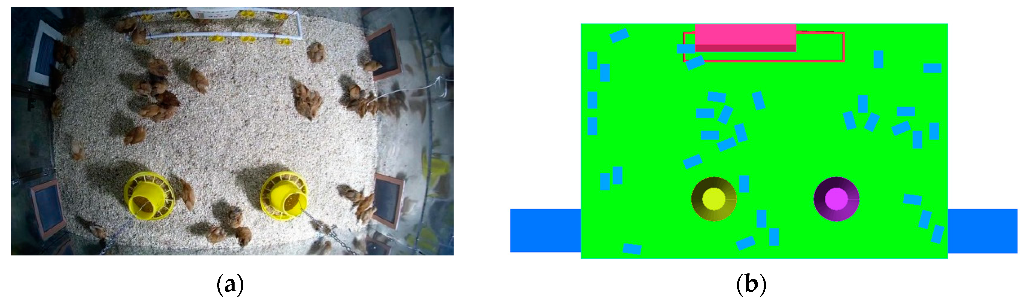
2.1. Research Objects and Measurement Methods

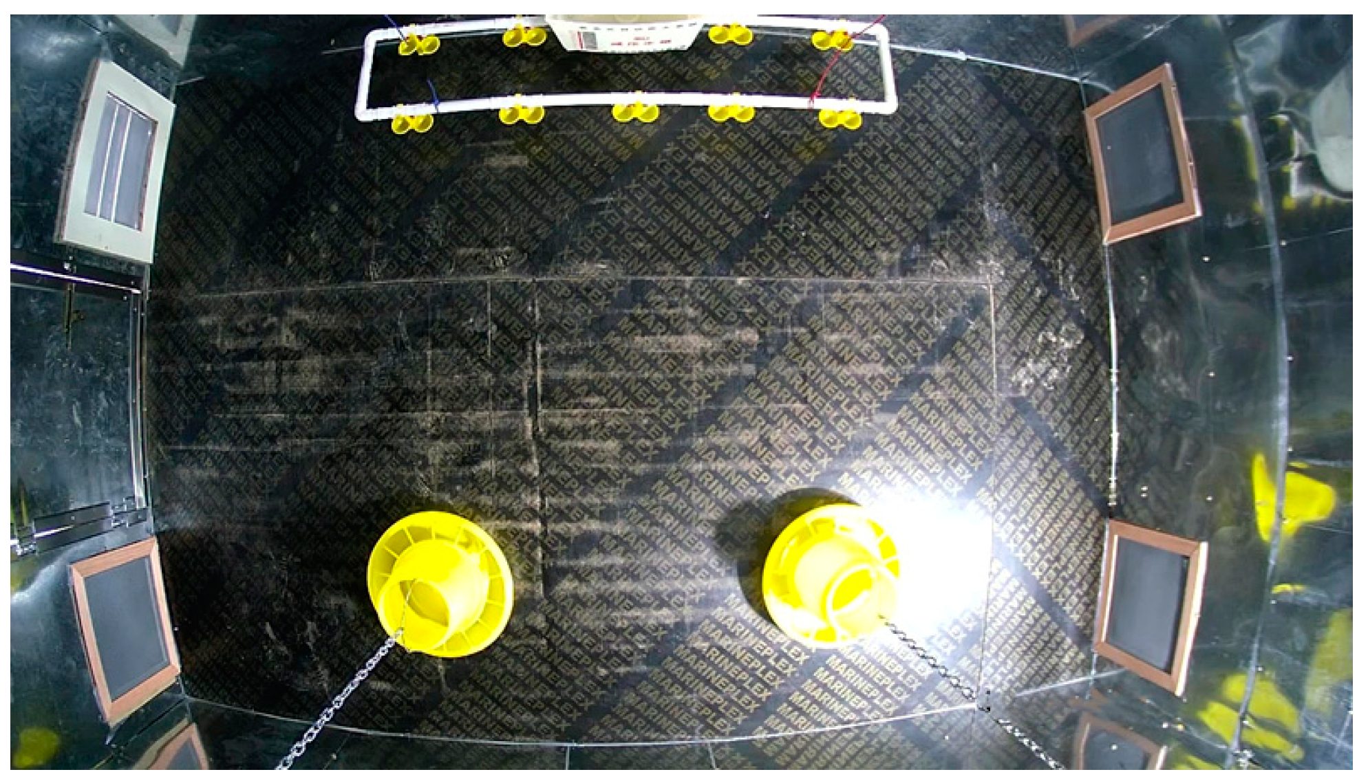
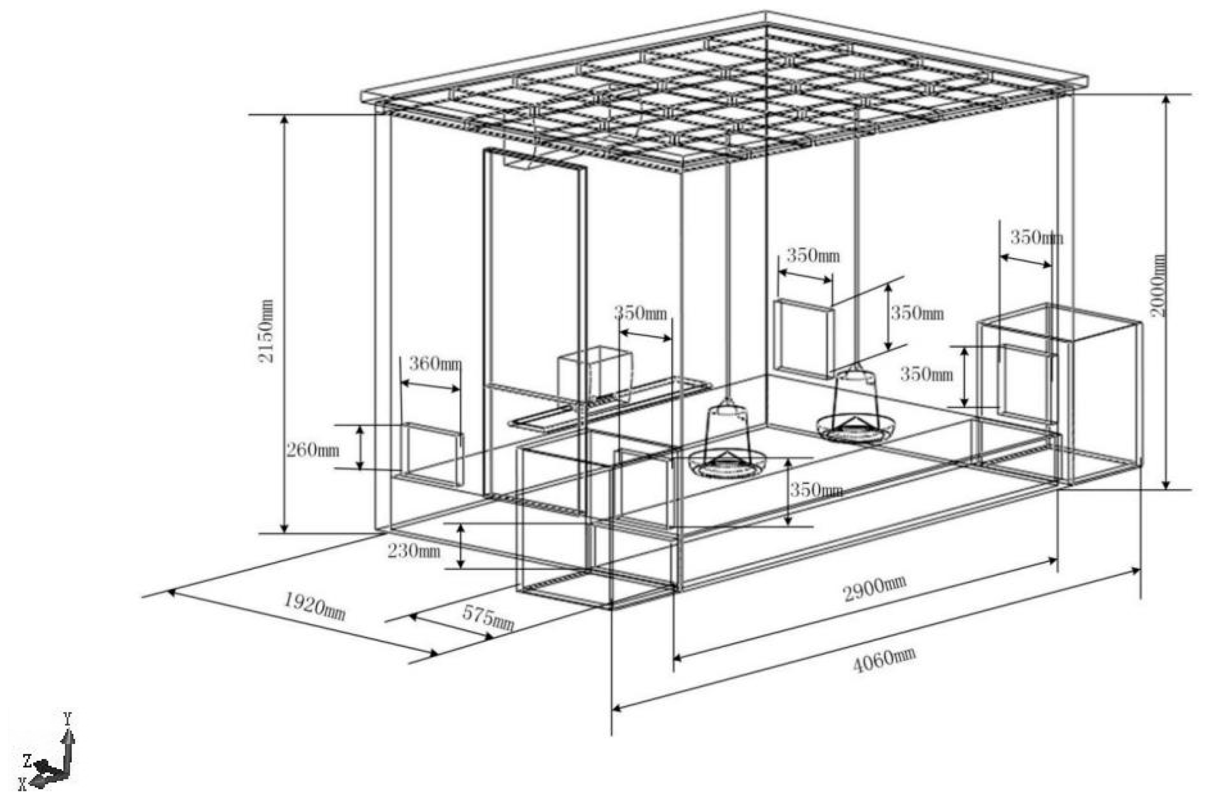
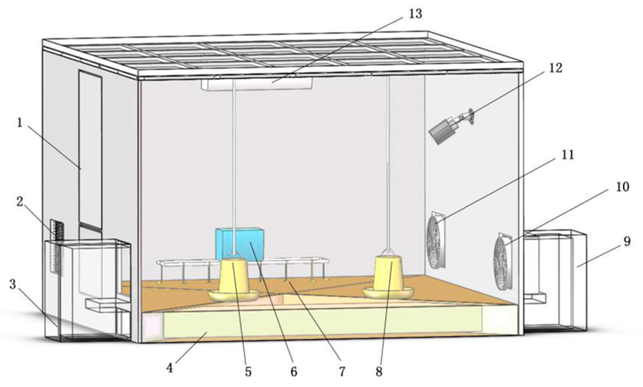
2.1.1. Layout of Experimental Site

Compared with large broilers farms, the small-scale broiler house in this experiment used a variety of sensors to detect the environmental parameters, which is easier to manage and more intelligent than large farms.The broiler house for the experiment is located in the Jinniuhu Subdistrict, Luhe District, Nanjing City, Jiangsu Province. The experiment started on 20 July 2018 and lasted for 21 days. The broiler house consists of two symmetrical chambers. The four walls around the broiler chamber are made of 55 mm-thick colored steel–polystyrene sandwich plates. Each chamber is 1.9 m in width, 2.9 m in length, with a total area of 5.51m2. The roof is slope-shaped with a height of 1.88 m on the west and 1.77 m on the east, which is convenient for draining rainwater. The ventilation system in the chamber consists of an air inlet, an air outlet, and an internal circulation. The internal circulation refers to the part where the openings at both ends are connected through pipes. Fan A and Fan B were arranged at the air outlet and the internal circulation air inlet, respectively. A Pulin Leshi 400 axial flow negative pressure fan was selected, with a rated air volume of 9000 m3/h and theoretical applicable area of 20–35 m2. Frequency conversion controllers were used to change the frequencies at different temperatures to create an optimal ventilation environment for broilers. Since the internal structures of the two broiler chambers were completely consistent, this paper only analyzed the ventilation structure of one chamber. Figure 1 shows the internal environment of the broiler chamber. Figure 2 shows the structure and dimensions of the chamber. Figure 3 presents the three-dimensional chamber model established by SolidWorks.

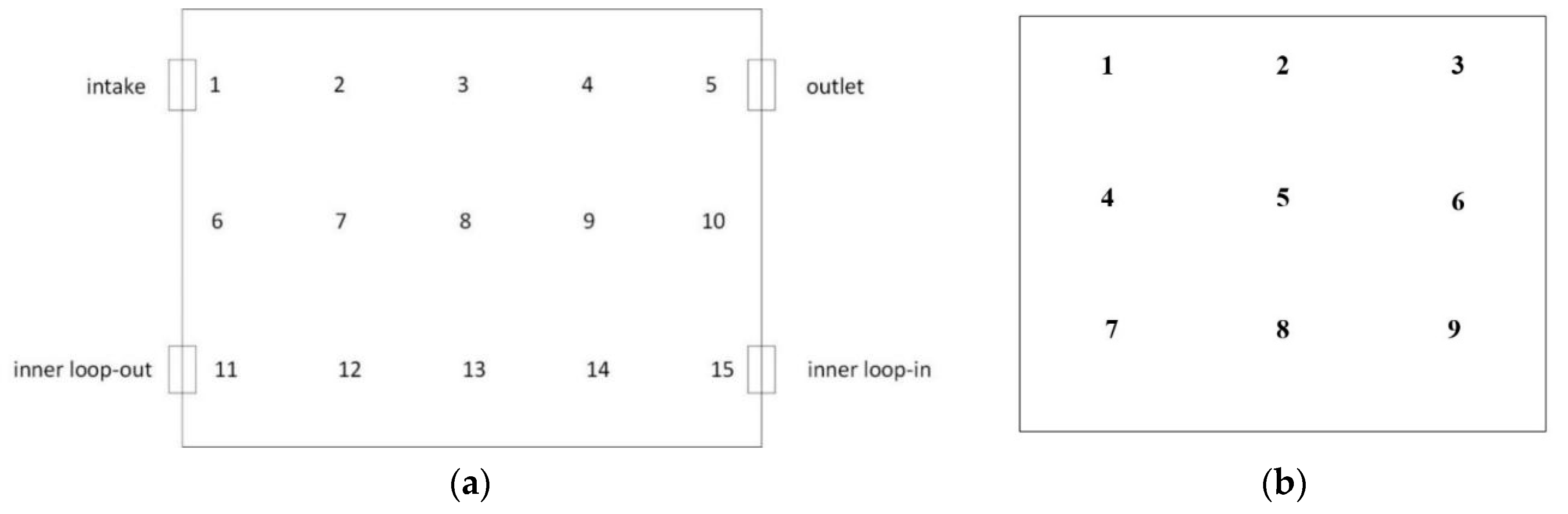
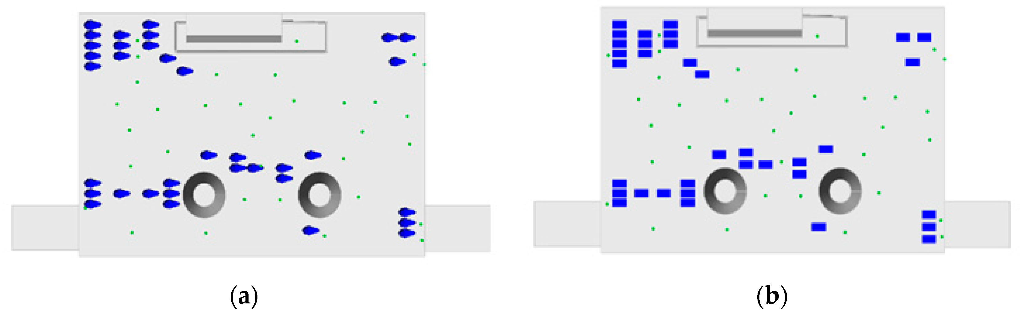
2.1.2. Selection of Measurement Points

According to the average height of broilers and a certain active area, the plane of 20cm above the ground was selected. The selected plane was divided into three lines, with five points in each line. Thus, a total of 15 measurement points was set, as shown in Figure 4. The wind velocity was measured using a Testo 405i handheld hot-wire anemometer with a measurement range of 0~30 m/s and a measurement error of ±(0.1m/s+5%). Since the broilers might interfere with the measurement work in the broiler chamber, the measured data were drawn from the empty broiler chamber after the breeding. The velocity of the fan inlet was acquired by taking an average of thenine points at the air inlet.The measurement points are shown in Figure 4b. Table 1 displays the measured wind velocity data of the nine points at the air inlet under three working conditions. The measured wind velocity data were transmitted to a mobile phone through Bluetooth, and they could be read and stored by the mobile phone.

2.1.3. Ventilation System

Fan A and Fan B are installed at two different air vents and work independently. They perform frequency modulation and temperature control according to the actual indoor temperature. The specific scheme is shown in Table 2. Since the experiment was conducted in summer in Jiangsu, the temperature at night is generally higher than 24 °C, so the 10 Hz working condition of Fan A is not met and, therefore, the simulation experiment did not study this. Because the broiler chamber is set outside the chamber, the sun shines directly on it, and sometimes the temperature is higher than 34 °C. To ensure the continuity of the experiment, the air conditioner was utilized to avoid high temperatures at which the broiler would have a severe thermal emergency response. At this time, the air conditioner is only used to reduce the indoor temperature, and this paper does not study this working condition. The simulation analysis in this paper is mainly based on five working conditions, as shown in Table 2.

2.2. CFD Model

2.2.1. CFD Control Equations

CFD is a kind of numerical simulation under the control of basic flow equations. In the numerical calculation, the air is considered as a continuous, steady, and incompressible Newtonian fluid. The continuity equation is also a mass conservation equation, and any flow movement must satisfy the Law of Conservation of Mass [19].
(1) Mass conservation equation
( ρ u ) x + ( ρ v ) y + ( ρ w ) z = 0
where, ρ is the fluid density, and u, v, and w are the components of the velocity vector in x, y, and z directions, respectively.
(2) Momentum conservation equation
( ρ u i ) t + ( ρ u i u j ) x j = p x i + τ i j x i + ρ g i + F i
where, p is the static pressure on the fluid microelement body, t is time, and g i and F i represent the gravity volume force and other external volume forces acting on the microelement body in the i direction, respectively. τ i j is the viscous stress tensor acting on the surface of the microelement body due to the molecular viscous effect.

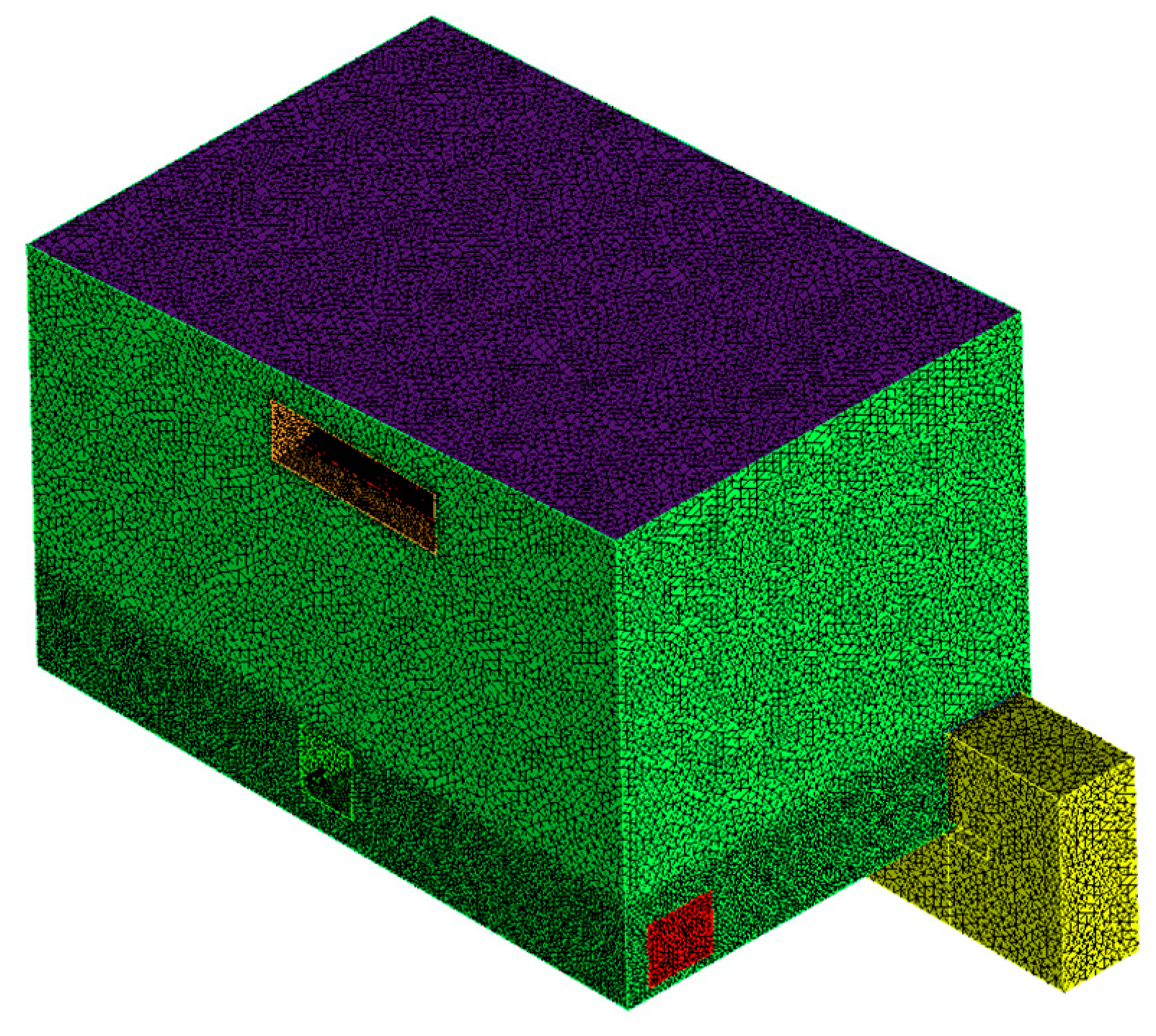
2.2.2. Mesh Division of the Broiler Chamber

In order to improve the calculation speed and meshing quality, a three-dimensional model was established in ICEM CFD15.0 according to the coordinates of each point. At first, the 1:1 broiler chamber model was simplified, and the steel frame structure at the top was removed. The internal structure was simplified without affecting the CFD simulation results. Non-structural meshes were selected to mesh the empty broiler chamber. The maximum side length of the mesh was set to 0.05 m. Since the main area of activity of broilers is located at the bottom of the broiler chamber, the ventilation condition on the ground surface is more worthy of our attention. The meshes were increased in density from a 0.6 m-high plane to the bottom of the empty chamber with a total cell number of 7,494,859, and the mesh inspection quality was greater than or equal to 0.34, which meets the calculation requirements. Mesh division of the broiler chamber in ICME CFD is shown in Figure 5.

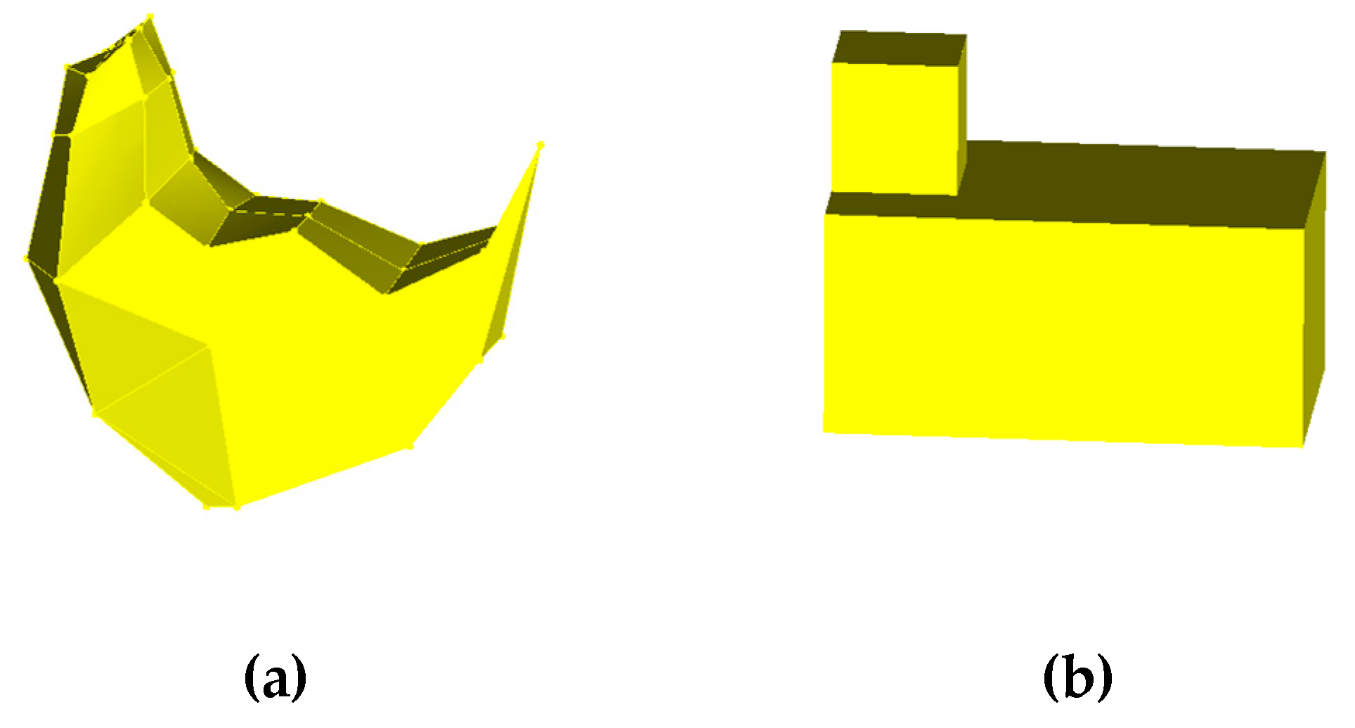
2.2.3. Broiler Model

Simplification of Broiler

Cheng et al. [15] simplified a single broiler to three different degrees, including a body only model, a broiler body model, and an ellipsoid model. After simulation and comparison, they finally chose the body only model as the research model. Chen [20] used a block model for CFD research on the broiler chamber. For the model of this project, it was necessary to determine a suitable model. In this paper, 35 seven-week-old yellow feather broilers were studied in the broiler chamber, and the chamber space was small, so geometric modeling could be carried out on a single broiler to improve the simulation accuracy. At the same time, in order to improve the calculation efficiency and accuracy, the broiler was simplified to a certain extent according to the original volume, as shown in Figure 6, (a) shows the body only model, and (b) shows the block model.

Efficiency Calculation and Selection

As shown in Figure 7, 35 measuring points were randomly selected from the position 15 cm away from the ground for comparison of model simulation results, and the corresponding velocity values of the 35 measuring points in the two models were drawn into the comparison chart of efficiency verification of wind velocity, as shown in Figure 8.
From Figure 8, it can be seen that the simulation results of the body only model and the block model have good consistency, and the trend is consistent. The average absolute error between the body only model and the block model was 0.12, and the error between the two sets of simulation values was small, indicating that the impact on the wind field in the broiler chamber was approximate. Table 3 shows the efficiency comparison of different models.
Under the distribution of two different broiler models, the mesh division time and Fluent numerical calculation time were counted, the mesh division number and convergence calculation time length were compared, and an appropriate broiler model was selected for the research in this paper. The computer processors were Intel ®Xeon E7-4830 @2.13 GHz and Intel ®Xeon E5-2660 V4 @2.0 GHz, respectively, with 64.0 GB of installed memory. The mesh division time of the block model and the body only model increased by 0.24 and 4.46 times, and the mesh number increased by 0.11 and 4.35 times, respectively. The mesh quality of the empty chamber was better than the mesh quality of the chamber with the block model, and both of them were better than the mesh quality of the chamber with the body only model. The calculation time of the block model and the body only model using Fluent increased by 1.48 and 5.5 times compared with the empty broiler chamber model. In terms of computational efficiency, the block model of broilers had greater advantages. Therefore, the block model was selected as the prototype to be studied in the next step.

2.3. Solver Parameter Settings

After the mesh model was completed, Fluent 15.0 software was used to perform the simulations of the empty broiler chamber, the broiler chamber with the block model, and the age of air in the broiler chamber with broilers under different working conditions. The simultaneous study of PIV and numerical simulation for a broiler house was conducted by Sun. Comparing the results of the two, it was found that the standard mean square error between the simulated values by the RNG k-ε turbulence model and the measured values was less than 0.25 and that the simulated values were more accurate [14]. Cheng et al. [17] explored the effects of flow resistance by considering the geometry of the broiler models (full geometry, ellipsoid, and maternal model in which the head, neck, and legs were ignored) and spatial distribution. In the wind tunnel experiment, five full geometric models were used to represent the broilers, and the model verification was performed using numerical simulation. Different turbulence models were evaluated, and the RNG k-ε model showed better performance than the other models. Specific parameters are given in Table 4.

2.4. Broiler Chambers
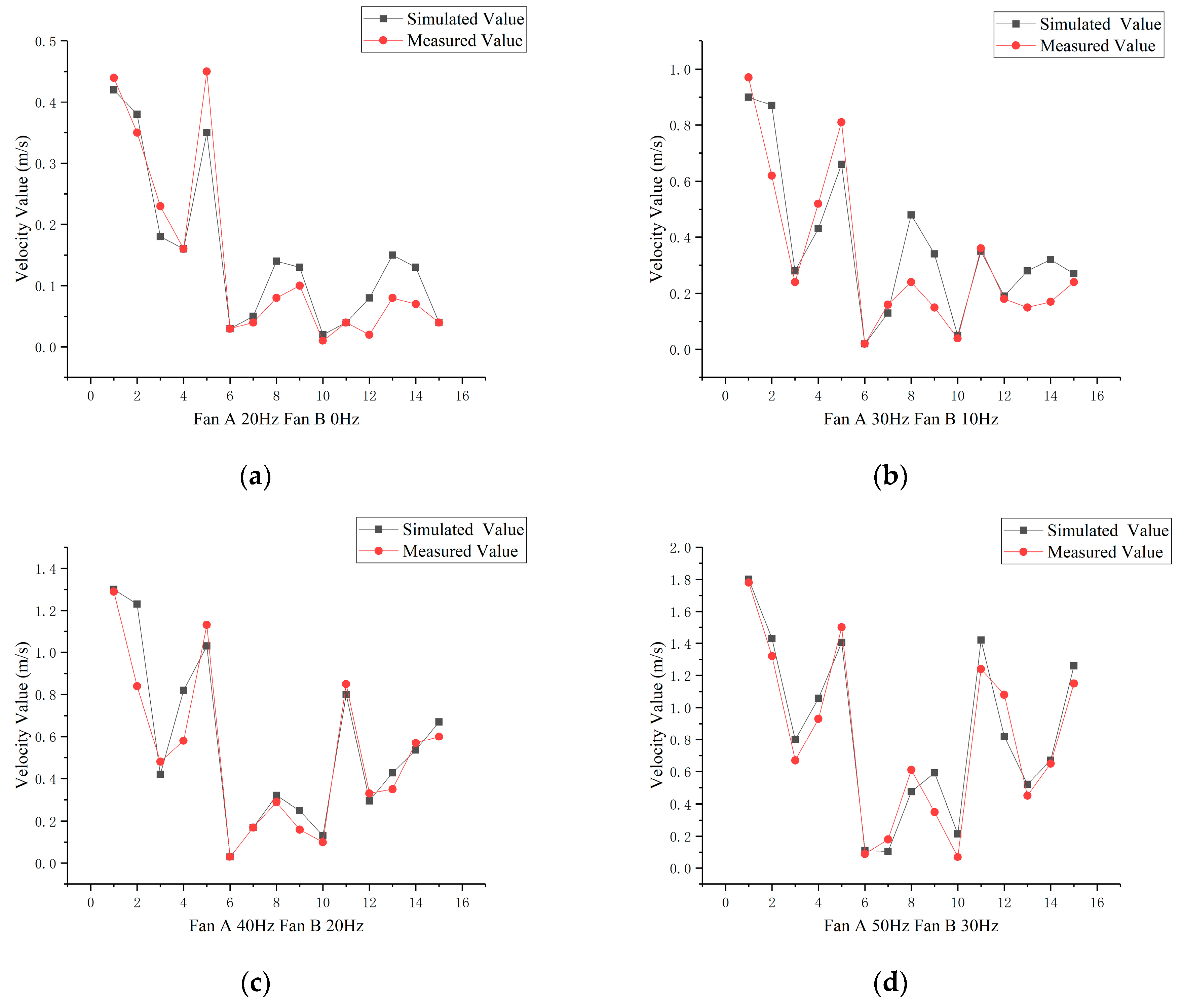
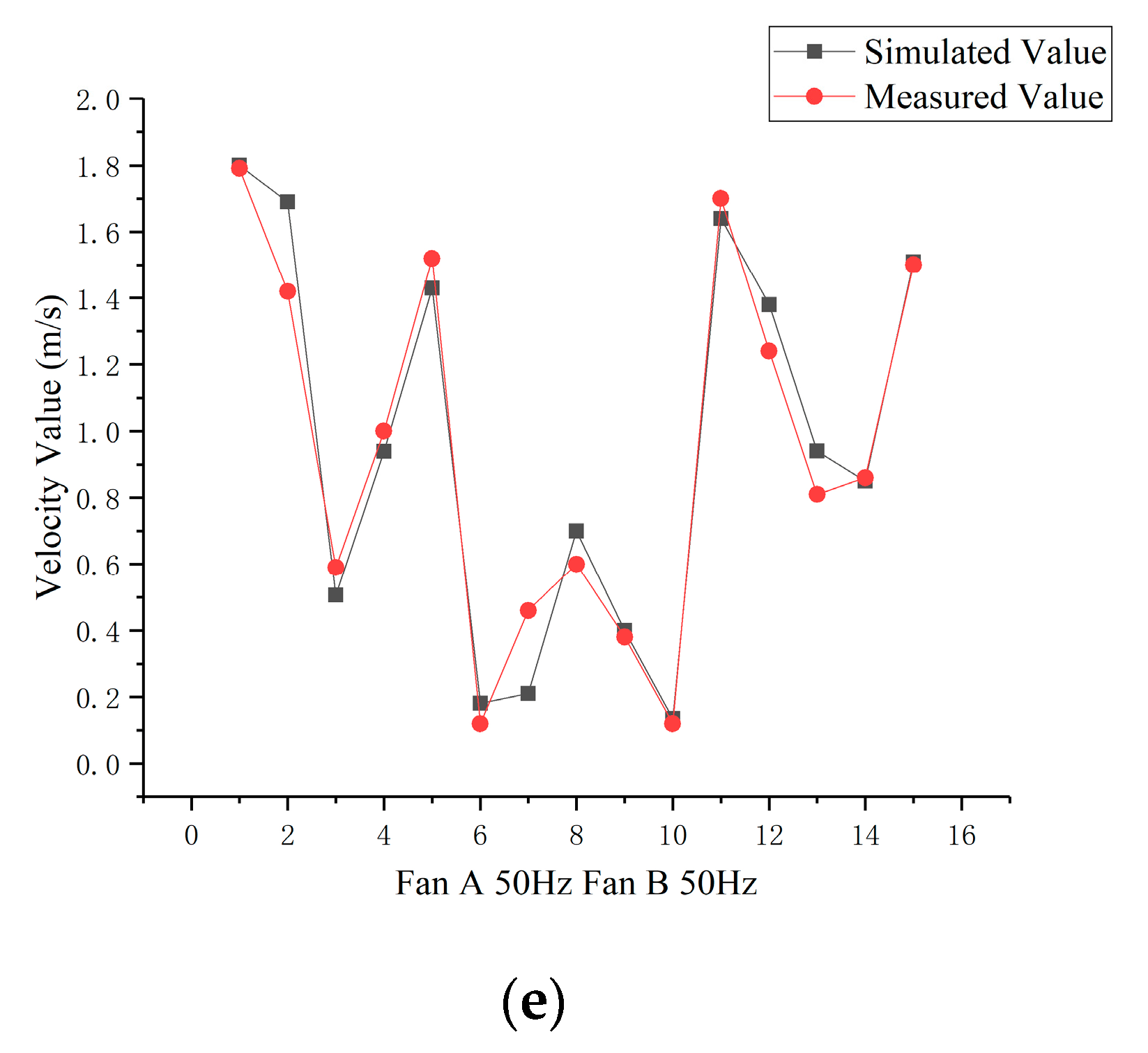
In the simulation of the wind field in the broiler chamber, the location distribution of broilers had different effects on the wind field. From the video, we randomly selected an arrangement photo of the broiler positions, shown in Figure 9a. As the basis for the distribution of broilers, a simulated experimental arrangement of the broiler chamber with broilers was carried out, as shown in Figure 9b. This paper mainly observed the wind velocity and the wind velocity flow field arrangement in the random distribution area of broilers, compared the velocity of the wind field in the empty broiler chamber, and analyzed the influence of broilers on the wind field in the broiler chamber, so as to make better improvements and optimizations for future research.

2.5. RMS Error

RMSE (Root mean square error) is very sensitive to extremely large or small errors in the two sets of data, so it can reflect the approximation of the two sets as well as the extent to which the simulated values deviate from the measured values.RMSE can be calculated by Equation (3).
RMSE = i = 1 n ( X o b s , i X m o d e l , i ) 2 n
where, n = 15 is the number of measurement points, i = 1,2,……n. X o b s , i is the measured value of point i, and X m o d e l , i is the simulated value.

2.6. Control Equation of Age of Air

The age of air refers to the time taken for fresh air to travel from the entrance to each mesh cell, which can reflect the ventilation situation in the chamber and the residence time of airflow, thus reflecting the replacement velocity of indoor fresh air. Therefore, the age of air was used as an index to evaluate the air quality in the broiler chamber in this paper [21]. The control equation of steady-state age of air is given as Equation (4).
( μ τ ) ( Γ · τ ) = 1
where, μ is the velocity of air (m/s), τ is the age of air (s), Γ is the diffusion coefficient, and = ( / x , / y , / z ).

3. Results and Discussion

3.1. Wind Velocity Simulation of Empty Broiler Chamber under Different Working Conditions

3.1.1. Numerical Comparison of Monitoring Points

Figure 10 shows the measured and simulated values of the 15 measurement points in the empty broiler chamber under different working conditions. The simulated values of the 15 measurement points were obtained by the momentum conservation equation in Fluent. Figure 10 shows the results in sequence, from working condition 1 to working condition 5. The maximum absolute error values and RMSE values are shown in Table 5 after the data were exported and compared.
At the height of Y = 0.2 m, under different working conditions, the difference between the simulated values and the measured values is not large, and the variation rules are consistent. The RMSE in this research was 0.19 m/s, which is close to the result of 0.16 m/s by Yao [16], and the maximum absolute error was 0.27 m/s, which shows that the CFD model and the adopted boundary conditions are suitable for this smart broiler chamber model. Therefore, the boundary conditions corresponding to each working condition were obtained, and then they were applied to a broiler chamber for the simulation experiment.

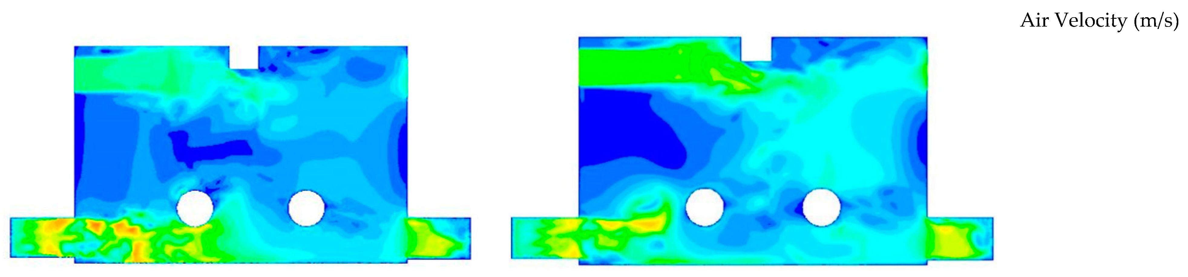
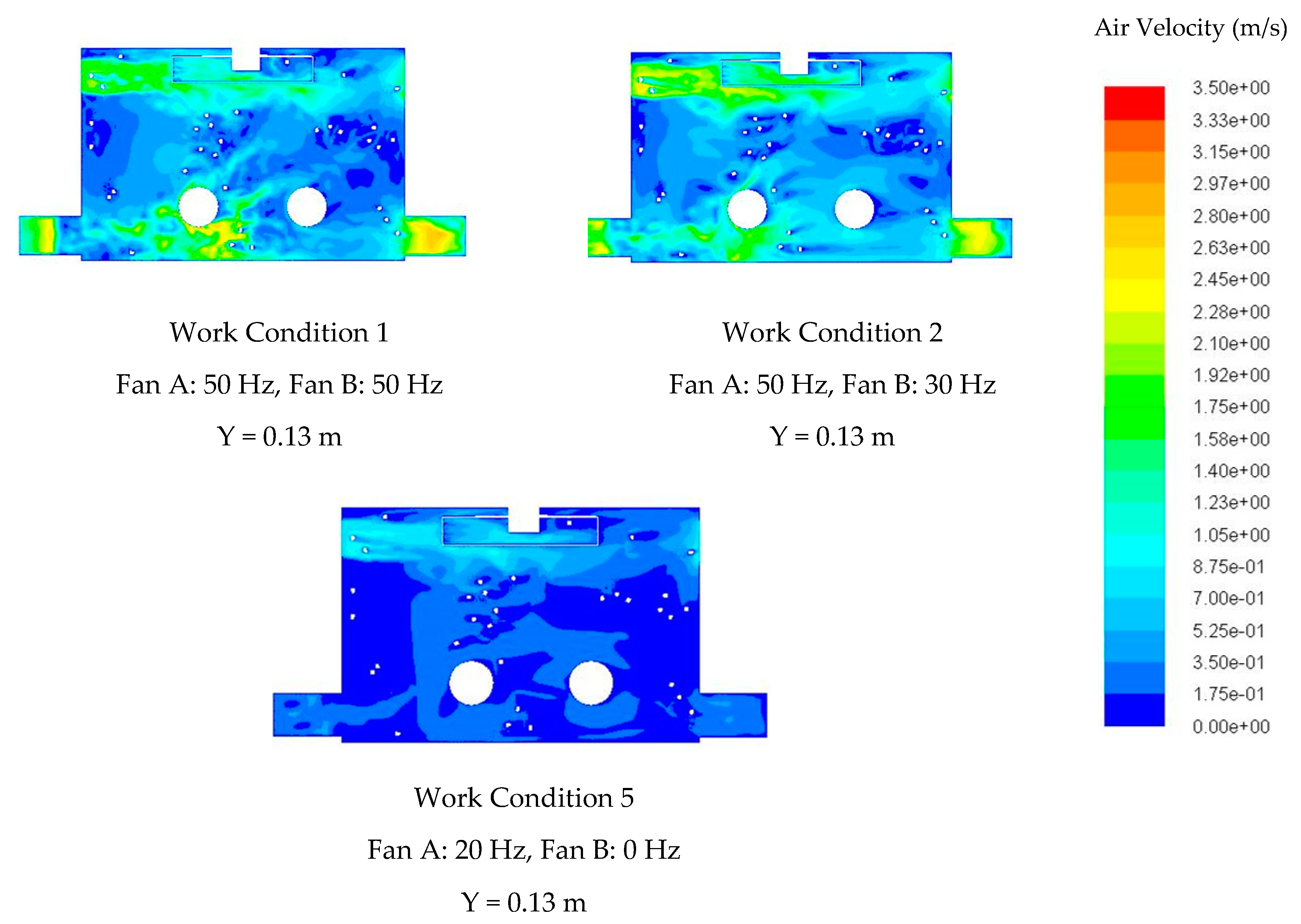
3.1.2. Analysis of Velocity Contours

Air velocity contours of the empty chamber were arranged in sequence from working condition 1 to working condition 5. As shown in Figure 11, the research of air velocity on the Y-axis plane of the empty chamber was at the height of 0.2 m in order to compare the velocity relationship among different working conditions, the colormap of the contour was unified, and the color in the velocity contour corresponded to the velocity in the colormap. Therefore, the velocity range under the five working conditions was 0~3.5 m/s, and the change rule of air velocity was studied in sequence.
In Figure 11, according to the contour of the five working conditions, the law of the plane wind velocity field in the broiler chamber at the height of Y = 0.2 m was relatively consistent. The wind velocities at the inlet and outlet were large, and there was obvious convection at the two opposite outlets. The velocity at the inlet was large, and fresh air was fed into the chamber. The five contours all had obvious high-velocity wind areas at about x = 0.6 m from the entrance, which was due to the influence of the water pipe of the water tank, causing the airflow to rise or fall along the pipe wall. Working condition 5 did not open the internal circulation system, and Fan A frequency was low, which can allow a small amount of ventilation. There was no wind at the two corners of the internal circulation side. The wind field uniformity of the broiler chamber was not high, and the suitable living area for broilers was limited. Fan A and Fan B worked together when the internal circulation system was started, and fresh air flowing to the middle of the broiler chamber circulated to the two fan ports. The air flowing through Fan A was directly exhausted from the broiler chamber, while the air flowing through Fan B was blown out from the other side through the internal circulation pipeline. By comparing working conditions 1 and 2, when the frequency of Fan B increased, the weak wind area in the plane could be effectively reduced.
Under the working condition 1, the plane with Z = 0.2 m in the broiler chamber shows the contour of the wind velocity field on the internal circulation vertical plane. The wind was drawn into the ventilation duct from Fan B, and the airflow direction at the wall near the outlet side formed a certain angle with the wall, which made the wind vector line at the wall denser and improved the wind velocity at the top of the inlet wall. Therefore, a larger vortex was formed in the broiler chamber along the X direction, so that the upper airflow could be driven to the lower part to exit the broiler chamber through airflow circulation. Under these five working conditions, the higher the internal circulation frequency, the more uniform the wind velocity field as a whole, indicating that the design of internal circulation has a great effect on the wind-velocity uniform distribution of the broiler chamber.

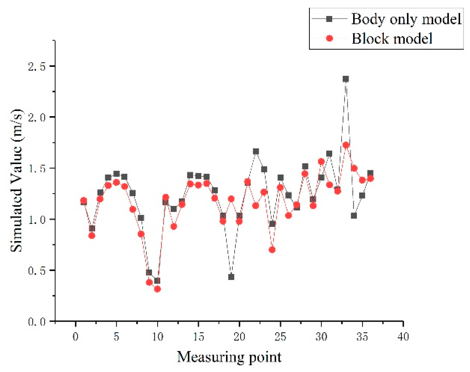
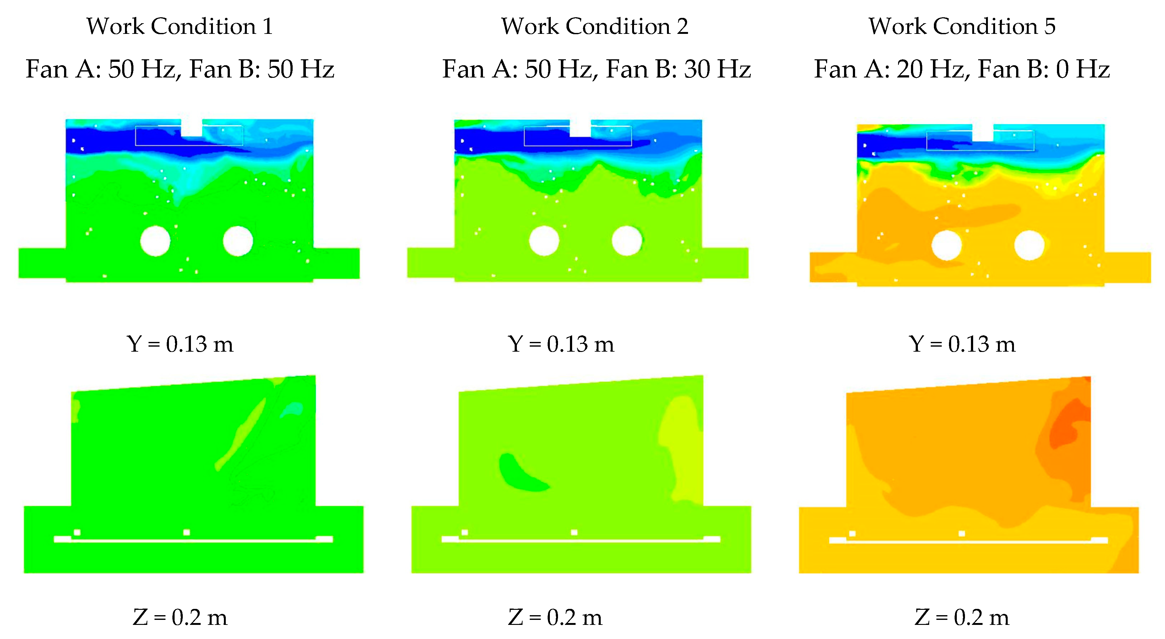
3.2. Simulation of the Broiler Chamber with Broilers under Three Common Working Conditions

Since the simulated and measured values of different working conditions under the empty broiler chamber were close to each other, the determined boundary conditions under the empty broiler chamber were applied to the model of the broiler chamber with broilers. The temperature of the broiler chamber in which broilers are put was relatively higher than that of the empty chamber, so the working conditions 1 and 2 were commonly used during the day in summer and the working condition 4 was used at night. The following is a study on the wind velocity field of the broiler chamber with broilers under three common working conditions. The wind velocity contours are shown in Figure 12.
The apparent temperature of broilers was generally analyzed by measuring the average skin temperature of side face, ears, comb, and lower leg, so the height of the velocity contour was selected as Y = 0.13 m (the average height of the middle part of the head in the broiler chamber). In the study from Yahav, the most suitable wind velocity was 2.0 m/s under a high-temperature environment (35 ± 1.0 °C). At that wind velocity, the body temperature was the lowest, and overhigh (3.0 m/s) or overlow (0.8m/s) wind velocities will raise the body temperature [21]. Zhang et al. [22] conducted experiments on 42-day-old broilers at 26 °C, 29 °C, and 32 °C with 0, 0.5 m/s, 1m/s, 1.5m/s, and 2.0m/s wind velocities. Under the condition of relatively high temperatures, considering the ventilation benefits, the optimum wind velocity was 1.2 m/s. According to Figure 12, the contours of working condition 2 and working condition 1 were more uniform in the wind velocity field due to the shielding and guiding effects of broilers on airflow compared with the contours of the same working condition of the empty chamber. The wind velocity at the vent can reach 2 m/s, which is favorable for the rapid emission of high-temperature gas. Therefore, when the weather temperature reaches above 30 °C, it is more suitable for broilers to gather near the vent. Most of the wind velocity values in the broiler chamber were above 0.875 m/s, which is close to the most suitable wind velocity, and there was almost no windless area, thus ensuring the normal living environment of broilers and avoiding a heat stress reaction. Working condition 5 corresponds to a temperature range of 24~26 °C. This condition mainly occurs at night when the air temperature is suitable for broilers and the fan is not necessary to increase the wind speed to cool the broilers, but needs to achieve continuous ventilation of the house.

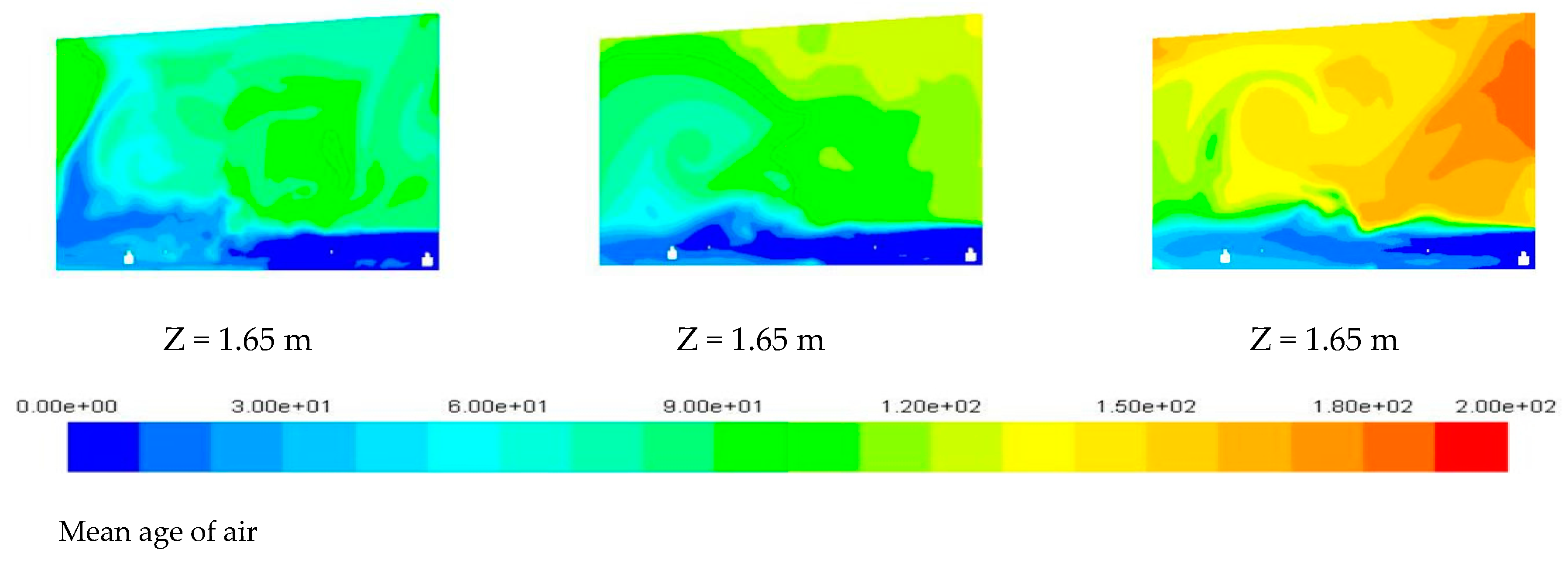
3.3. Simulation of the Age of Air

The good ventilation environment in the broiler chamber not only cools the surface of the broiler and makes it feel comfortable, but also needs to provide sufficient fresh air to the broiler chamber. Therefore, the age of air under the broiler chamber was simulated. The age of air with Y = 0.2 m (broiler living plane), Z = 0.2 m (vertical section of internal circulation), and Z = 1.65 m (vertical section of air inlet and outlet) were simulated under three working conditions in turn. The contours of the age of air are shown in Figure 13.
In Figure 13, according to the contours, the ages of air were as follows: Working Condition 1 < Working Condition 2 < Working Condition 5, which proves that the increase of fan frequency greatly improves the ventilation efficiency of the broiler chamber. It can be seen from the contours of the plane at Y = 0.13 m that the convection area of the inlet was contrasted with the inner side. The ages of air at the inlet and outlet were younger, and fresh air changed faster. The age of air inside the broiler chamber was older than that at the air duct. Working conditions 1 and 2 need to use internal circulation. The age of air in the middle of the broiler chamber was younger than that in working condition 5. The internal circulation promotes the air circulation in the plane. The fresh air with the Z = 0.2 m section first reached the outlet and then reached the internal circulation outlet. The wall corner of the internal circulation inlet continued to move in the two directions of the internal circulation pipeline and wall climbing. The age of air was old, and there were vortexes and weak wind velocity, which is not conducive to the replacement of fresh air. The wall near the internal circulation inlet had an older age of air. At the bottom of section Z = 1.65 m, the air inlet and outlet realized convection ventilation, which was the most efficient area for ventilation in the broiler chamber. Through velocity analysis, the wind velocity was relatively high, and the vortex was generated upward through wall–floor collision, which made a great contribution to the renewal of the upper air.
Yu et al. [23] analyzed the age of air of the cabin kitchen with a length of 5.6 m and a width of 3 m. The air in the cabin was highly disturbed, and the air freshness was higher. Our results showed that the age was within 60 s, the oldest age of air was 255 s, which appeared in the corner, and the age of air in the air inlet and outlet of the broiler chamber was also within 60 s. The oldest age of air in the broiler living area was about 100 s under the working condition 1 and 150~180 s under the working condition 4, which was within a reasonable range. This showed that this ventilation system was conducive to timely updating of the fresh air inside the broiler chamber and to improving the living environment of the broilers.

4. Conclusions

The conclusions of this research are summarized as follows:
(1) Through actual measurement, the three-dimensional model of the broiler chamber was established and simulated in Fluent software. The comparison between the simulation results and the actual measurement results showed that the RMSE of the wind velocity at each measurement point was up to 19.1%, and the maximum absolute error was 0.27 m/s, which shows the effectiveness of the CFD model.
(2) The wind velocity and the age of air in the broiler chamber were simulated and analyzed. The design of setting different frequencies for the fan met the requirement of setting appropriate temperatures in different periods. In the high-temperature area (above 30 °C), the wind velocity at the air inlet and outlet was close to 2 m/s, which is beneficial to the cooling of broilers. The internal wind velocity could be regulated above 0.8 m/s, which meets the ventilation requirement in summer. The age of air of the broiler chamber could be renewed within about 100s at the bottom of the chamber in a relatively high-temperature environment. When starting the working condition 5 at night, ventilation could be carried out in all parts of the chamber within 150~180 s. Compared with the residential ventilation using fans, the age of air of the broiler chamber in this research was much younger, so the design of the ventilation system in the broiler chamber is superior to the common residential standard.
(3) The height of the air inlet and the center of the fan in the broiler chamber were set to be the same as those in the empty chamber. When the broiler chamber is mechanically ventilated, a large amount of airflow circulates in the lower part, effectively improving the ventilation and cooling effect. As a result, more airflow passes through the surface of the broiler chamber. As the density of polluted gas is small, the polluted gas mostly gathers at the top, and needs to be circulated to the bottom through the vortex and then blown out from the air outlet, thus reducing the efficiency of pollutant emission. Based on this design, an exhaust fan can be applied to the upper part of the broiler chamber to improve the efficiency of pollutant emission.

Author Contributions

X.Z. and X.Q. conceived and designed the experiments; X.Z., S.Z. (Shikai Zhang), A.D., B.F., S.Z. (Shixiu Zhang), and Y.Q. performed the experiments and analyzed the data; S.W., H.Y., and Y.W. helped perform the data analysis; S.Z. (Shikai Zhang), A.D., and X.Z. wrote the paper.

Funding

This research was funded by the Fundamental Research Funds for the Central Universities of China (KYTZ201661), China Postdoctoral Science Foundation (2015M571782), Jiangsu Agricultural Machinery Foundation (GXZ14002), and University Student Entrepreneurship Practice Program of Jiangsu Province (No. 201810307010P).

Conflicts of Interest

The authors declare no conflict of interest.

References

  1. Park, G.; Lee, I.; Yeo, U.; Ha, T.; Kim, R.; Lee, S. Ventilation rate formula for mechanically ventilated broiler houses considering aerodynamics and ventilation operating conditions. Biosyst. Eng. 2018, 175, 82–95. [Google Scholar] [CrossRef]
  2. Yao, H.; Sun, Q.; Zou, X.; Wang, S.; Zhang, S.; Zhang, S.; Zhang, S. Research of yellow-feather chicken breeding model based on small chicken chamber. Agric. Eng. 2018, 56, 91–100. [Google Scholar]
  3. Du, L.; Yang, C.; Dominy, R.; Yang, L.; Hu, C.; Du, H.; Li, Q.; Yu, C.; Xie, L.; Jiang, X. Computational fluid dynamics aided investigation and optimization of a tunnel-ventilated poultry house in china. Comput. Electron. Agric. 2019, 159, 1–15. [Google Scholar] [CrossRef]
  4. LEE, I.-B.; SASE, S.; SUNG, S.-H. Evaluation of CFD accuracy for the ventilation study of a naturally ventilated broiler house. Jpn Agric. Res. Q. 2007, 41, 53–64. [Google Scholar] [CrossRef]
  5. Seo, I.H.; Lee, I.B.; Moon, O.K.; Kim, H.T.; Hwang, H.S.; Hong, S.W.; Bitog, J.P.; Yoo, J.I.; Kwon, K.S.; Kim, Y.H.; et al. Improvement of the ventilation system of a naturally ventilated broiler house in the cold season using computational simulations. Biosyst. Eng. 2009, 104, 106–117. [Google Scholar] [CrossRef]
  6. Cheng, Q.; Li, H.; Rong, L.; Feng, X.; Zhang, G.; Li, B. Using CFD to assess the influence of ceiling deflector design on airflow distribution in hen house with tunnel ventilation. Comput. Electron. Agric. 2018, 151, 165–174. [Google Scholar] [CrossRef]
  7. Kic, P.; Zajicek, M. A numerical cfd method for the broiler house ventilation analysis. J. Inf. Technology in Agric. 2011, 1, 1–7. [Google Scholar]
  8. Bjerg, B.; Svidt, K.; Zhang, G.; Morsing, S.; Johnsen, J.O. Modeling of air inlets in cfd prediction of airflow in ventilated animal houses. Comput. Electron. Agric. 2002, 34, 223–235. [Google Scholar] [CrossRef]
  9. Norton, T.; Grant, J.; Fallon, R.; Sun, D. Improving the representation of thermal boundary conditions of livestock during CFD modelling of the indoor environment. Comput. Electron. Agric. 2010, 73, 17–36. [Google Scholar] [CrossRef]
  10. Mostafa, E.; Lee, I.; Song, S.; Kwon, K.; Seo, I.; Hong, S.; Hwang, H.-S.; Bitog, J.P.; Han, H.-T. Computational fluid dynamics simulation of air temperature distribution inside broiler building fitted with duct ventilation system. Biosyst. Eng. 2012, 112, 293–303. [Google Scholar] [CrossRef]
  11. Yao, J.; Guo, B.; Ding, W.; Shao, X.; Shi, Z. Structure optimization and validation of goose house ventilation system based on airflow field simulation by CFD. Trans. Chin. Soc. Agric. Eng. 2017, 33, 214–220. [Google Scholar]
  12. Li, W.; Shi, Z.; Wang, C. Numerical simulation of tunnel ventilation system of plane-raising enclosed henhouse. J. China Agric. Univ. 2007, 12, 80–84. [Google Scholar]
  13. Coradi, P.C.; Costa, D.R.D.; Visser, E.M.; Martins, M.A.; Tinôco, I.D.F.F. Thermal comfort evaluation in a broiler house utilizing computational fluid dynamics (CFD) software. In Proceedings of the CIGR International Conference of Agricultural Engineering, Viçosa, Brazil, 3 August 2008. [Google Scholar]
  14. Blanes-Vidal, V.; Guijarro, E.; Balasch, S.; Torres, A.G. Application of computational fluid dynamics to the prediction of airflow in a mechanically ventilated commercial poultry building. Biosyst. Eng. 2008, 100, 105–116. [Google Scholar] [CrossRef]
  15. Cheng, Q.; Wu, W.; Li, H.; Zhang, G.; Li, B. CFD study of the influence of laying hen geometry, distribution and weight on airflow resistance. Comput. Electron. Agric. 2018, 144, 181–189. [Google Scholar] [CrossRef]
  16. Sun, H.; Zhao, L.; Zhang, Y. Evaluating RNGk-εmodels using PIV data for airflow in animal buildings at different ventilation rates. ASHRAE 2007, 113, 358–365. [Google Scholar]
  17. Seo, I.; Lee, I.; Moon, O.; Hong, S.; Hwang, H.; Bitog, J.P.; Kwon, K.; Ye, Z.; Lee, J. Modelling of internal environmental conditions in a full-scale commercial pig house containing animals. Biosyst. Eng. 2012, 111, 91–106. [Google Scholar] [CrossRef]
  18. Zajicek, M.; Kic, P. Improvement of the broiler house ventilation using the CFD simulation. Agron. Res. 2012, 1, 235–242. [Google Scholar]
  19. Khosravi Nikou, M.R.; Ehsani, M.R. Turbulence models application on CFD simulation of hydrodynamics, heat and mass transfer in a structured packing. Int.Commun. Heat Mass Transf. 2008, 35, 1211–1219. [Google Scholar] [CrossRef]
  20. Jinru, C. Study of Indoor Environment Dynamic Simulation of Layer-House Based on the Model of Caged Pens of Porous Media. Master’s Thesis, Hebei University of Technology, Wuhan, China, 2015. [Google Scholar]
  21. Damin, Z.; Xiugan, Y. Numerical solution of age of air. J. Beijing Univ. Aeronaut. Astronaut. 1997, 23, 565–570. [Google Scholar]
  22. Shaoshuai, Z.; Huajie, D.; Minhong, Z.; Jinghai, F.; Ying, Z.; Meng, L.; Xiumei, L. Effects of air velocity and moderate ambient temperatures on physiological, endocrine and immune indices of broilers. Chin. J. Anim.Nutr. 2017, 29, 69–79. [Google Scholar]
  23. Yu, N. Numerical simulation of the air distribution of typical ship kitchen ventilation system. Ship Ocean Eng. 2018, 47, 89–92. [Google Scholar]
Figure 1. Internal picture of the experimental broiler chamber.
Atmosphere 10 00315 g001
Figure 2. The structure and dimensions of the experimental broiler chamber.
Atmosphere 10 00315 g002
Figure 3. The three-dimensional chamber model was established by SolidWorks with (1) chamber door, (2) air inlet, (3) internal circulation front air bellow, (4) internal circulation pipeline, (5) Feeder A, (6) water tank, (7) drinking water pipe, (8) Feeder B, (9) internal circulation rear air bellow, (10) Fan B, (11) Fan A, (12) camera, and (13)air conditioner.
Atmosphere 10 00315 g003
Figure 4. Point distribution: (a) The plane distribution position of the detection points; (b) The inlet distribution position of the detection points.
Atmosphere 10 00315 g004
Figure 5. Mesh division of the broiler chamber in ICME CFD (integrated computer engineering and manufacturing code for computational fluid dynamics).
Atmosphere 10 00315 g005
Figure 6. Schematic diagram of broiler model: (a) body only model, (b)block model.
Atmosphere 10 00315 g006
Figure 7. Distribution of two models for broilers: (a) body only model, (b) block model.
Atmosphere 10 00315 g007
Figure 8. Comparison of efficiency verification wind velocity between the body only model and the block model.
Atmosphere 10 00315 g008
Figure 9. Experimental arrangement of the chamber with broilers was simulated by the block model. (a) one video frame of broiler distribution, (b) modeling of broiler distribution in ICEM CFD.
Atmosphere 10 00315 g009
Figure 10. Numerical comparison of empty broiler chamber under (a)work condition 5; (b)work condition 4; (c)work condition 3; (d)work condition 2; and (e)work condition 1.
Atmosphere 10 00315 g010aAtmosphere 10 00315 g010b
Figure 11. Simulated velocity contour of the empty chamber with the colormap on the left.
Atmosphere 10 00315 g011aAtmosphere 10 00315 g011b
Figure 12. Simulated velocity contours of the broiler chamber with broilers.
Atmosphere 10 00315 g012
Figure 13. The contours of the age of air in the chamber with broilers.
Atmosphere 10 00315 g013aAtmosphere 10 00315 g013b
Table 1. The measured wind velocity values of the nine measuring points at the air inlet.
Measuring Point NumberMeasuring Velocity Values (m/s)
Fan A = 50 HZFan A = 30 HZFan A = 20 HZ
11.670.810.27
21.740.830.34
31.640.790.31
41.690.930.37
51.971.150.47
61.731.070.39
71.780.870.29
81.800.940.32
91.790.920.30
Average value1.760.920.34
Standard deviation0.0910.110.05
Table 2. The experimental plan of fan frequency based on five working conditions. RPM = revolutions per minute.
Number of Work ConditionTemperatureFan ARPM
(Fan A)
Fan BRPM
(Fan B)
Air Conditioner
>34 °C0030 Hz840On (set 30 °C)
132~34 °C50Hz140050 Hz1400Off
230~32 °C50Hz140030 Hz840Off
328~30 °C40Hz112020 Hz560Off
426~28 °C30Hz84010 Hz280Off
524~26 °C20Hz56000Off
<24 °C10Hz28000Off
Table 3. The efficiency comparison of different models.
Selected ModelTime
(Unit: s)
Number of CellsQuality of MeshesTime to Achieve Convergence
(Unit: h)
Empty chamber8037,494,859>0.351.35
Block model9938,310,070>0.342
Body only model438140,120,931>0.27.5
Table 4. Specific parameters of solver that were used in Fluent.
ParametersValues
Simulated stateSteady state
Turbulence modelRNG (the renormalization group) k-ε
Air density/(kg/m3)1.225
Aerodynamic viscosity/(Pa·s)
Dynamic mesh
1.83 × 10⁻⁵
Smoothing
Table 5. Error values under different working conditions.
ErrorTypeFan A 20 Hz
Fan B 0 Hz
Fan A 30Hz
Fan B 10Hz
Fan A 40Hz
Fan B 20Hz
Fan A 50Hz
Fan B 30Hz
Fan A 50Hz
Fan B 50Hz
Maximum Absolute Error (Unit: m/s)0.10.150.240.240.27
Root Mean Square Error (Unit: m/s)4.917.618.219.116.6

