Abstract
Tropical cyclones (TCs) are complex sources of atmospheric gravity waves (GWs). In this study, the Weather Research and Forecasting Model was used to model TC Soudelor (2015) and the induced elliptical structures of GWs in the upper troposphere (UT) and lower stratosphere (LS) prior to its landfall over Taiwan. Conventional, spectral and wavelet analyses exhibit dominant GWs with horizontal and vertical wavelengths, and periods of 16–700 km, 1.5–5 km, and 1–20 h, respectively. The wave number one (WN1) wind asymmetry generated mesoscale inertia GWs with dominant horizontal wavelengths of 100–300 km, vertical wavelengths of 1.5–2.5 km (3.5 km) and westward (eastward) propagation at the rear of the TC in the UT (LS). It was also revealed to be an active source of GWs. The two warm anomalies of the TC core induced two quasi-diurnal GWs and an intermediate GW mode with a 10-h period. The time evolution of dominant periods could be indicative of changes in TC dynamics. The FormoSat-3/COSMIC (Formosa Satellite Mission-3/Constellation Observing System for Meteorology, Ionosphere, and Climate) dataset confirmed the presence of GWs with dominant vertical wavelengths of about 3.5 km in the UT and LS.
1. Introduction
Atmospheric chemistry and climate are very sensitive to the variability of the tropical lower stratosphere (LS) [1]. In particular, tropical wave forcing significantly affects this key region [2]. Small-scale gravity waves (GWs) are ubiquitous multi-scale atmospheric waves in the tropical troposphere, which remain hard to fully observe and represent in models. Indeed, climate modeling has revealed that GWs could account for 59% of the 2% per decade increase of annual mean tropical upwelling in the LS and reduce cold-pole bias in the Southern Hemisphere [3,4]. Both parameterized and resolved GW simulations with Global Climate Models (GCM) supported the vertical coupling in the atmosphere–ionosphere system [5], with increasing dominance of GWs at higher altitudes and significant impacts on the large-scale flow [6]. Recently, Reference [7] reported that orographic and nonorographic GWs contributed evenly to GW forcing in the stratosphere. Thus, many operational numerical weather prediction (NWP) models now extend into the stratosphere and forecast seasonal time scales, requiring the implementation of accurate computationally optimal GW drag parameterizations [8]. Reference [9] proposed some key modifications and a stochastic approach to producing a quasi-biennial oscillation (QBO) with realistic amplitude and a period in a high-altitude NWP model. However, the ability to quantify GWs is subject to open debate in the tropical atmosphere [6,10].
Among GW sources, tropical cyclones (TCs) are well-organized mesoscale convective systems that produce a wide variety of intermittent nonorographic GWs in the tropics. However, both observations and modeling partially captured GW characteristics depending respectively on the observational instruments [11,12,13,14,15] and the model setup [16,17,18,19]. Reference [20] derived dominant low-frequency GWs with short vertical wavelengths of 1–3 km, horizontal wavelengths of 80–400 km and periods of 4.6–13 h in the upper troposphere (UT) and LS from radiosonde and FormoSat-3/COSMIC (Formosa Satellite Mission-3/Constellation Observing System for Meteorology, Ionosphere, and Climate) radio occultation (RO) datasets, while mesoscale modelling with a vertical resolution of about 500 m highlighted a wide spectrum of resolved GWs with horizontal wavelengths of 20–2000 km, short vertical wavelengths of 1.5–4 km and periods of 20 min–2 days and up to 25 km height in the LS. The accuracy of the first measurements of the vertical atmospheric profiles, of the refractivity, temperature, and pressure from FormoSat-3/COSMIC, was demonstrated by Reference [21]. Using FormoSat-3/COSMIC temperature profiles, both deep convections and GW activity were shown to affect the variations of the tropopause parameters in the tropics [22].
Significant progress has been made in the forecasting of TCs in the last decades, including track, intensity, and structure [23]. Nevertheless, forecasting intensity changes in the TCs remains a challenging issue strongly dependent on our understanding of multiscale dynamical processes, such as wave processes. Improving TC intensity forecasting is one of the highest priorities, especially prior to and during landfall because of fast coastal population growth. In particular, some observation and numerical studies supported that TC-induced GWs in the UT and LS could be indicative of TC intensity. Reference [24] correlated the maximum surface wind speeds of TCs Dina (2002) and Faxai (2001) with GW energy density. A 10-season climatology confirmed the link between increasing GW energy density and TC activity [25]. Recently, atmospheric infrared sounder (AIRS) observation indicated a correlation between the activity of stratospheric GWs with horizontal and vertical wavelengths of about 90–100 km and 10–15 km, respectively, and TC intensity change [26]. At lower altitudes, Reference [27] reported a correlation between TC intensity and the wave amplitudes of high-frequency GWs (periods < 1 h) with radial wavelengths of 2–10 km.
Previously, Reference [28] described GWs in the eye of TC Andrew (1992) as a typical feature during the development of TCs. Pronounced GW fluctuations, with a period of 3 h, were identified in the eye and the eyewall during the deepening stage of the simulated asymmetric inner core. Reference [29] revealed oscillations, with periods of about 2 h, in wind speed and pressure surface around the eye and eyewall, more significant at the side with higher wind speeds in asymmetric TCs. Indeed, the TC vortex was rarely symmetric during its lifecycle due to asymmetric instability resulting from interactions between the TC and its environment, especially during intensity changes. Asymmetries near the eyewall were mostly dominated by the wave number one (WN1) component [30]. The WN1 asymmetry, in the dynamic and thermodynamic field, is mainly caused by the environmental vertical wind shear among, for example, land–sea contrast during landfall, topography blocking, β-effect, sea-surface temperature, and interactions with upper-level troughs [31]. During the intensification of TC Ivan (2008), prior to landfall over Madagascar, Reference [20] diagnosed a WN1 asymmetry with evidence of a quasi-inertia stratospheric GW with horizontal and vertical wavelengths of 300–600 km and 2–3 km respectively and a mean period of 13 h. The TC-induced GW was found to propagate eastward at a speed of about 13 m/s and upward in the westward stratospheric background wind.
Finally, previous numerical modelling indicates that the coarse vertical resolution of simulated GWs does not ensure the coupling between vertical and horizontal scales. This coupling is crucial to the spectral characteristics of short-scale GWs with vertical wavelengths <5 km, which are mostly derived from measurements of high-vertical resolution sounding. Therefore, in this study, a realistic mature TC with high-vertical resolution was simulated to investigate the elliptically polarized GWs in the troposphere and LS when the Category 3 TC Soudelor (2015) approached Taiwan, starting early on 5 August and going until late on 7 August, prior to landfall. The description of the model and methods of analysis are described in Section 2. Section 3 provides an overview of TC Soudelor and validates the simulation. The analysis of the simulated TC-induced GWs prior to the landfall of TC Soudelor and the observations are reported in Section 4. Conclusions are drawn in Section 5.
2. Description of the Model and Methods of Analysis
The Advanced Research Weather Research and Forecasting model (WRF-ARW) version 3.7.1 [32] was used to simulate TC Soudelor’s (2015) approach to Taiwan between 5 August 00:00 UTC and 8 August 00:00 UTC. The control run (CTL) was based on a triple two-way interactive nested grid of 27 km (domain D1), 9 km (domain D2) and 3 km (domain D3), with respective time steps of 90 s, 30 s and 10 s, and grid points of 100 × 60, 174 × 135 and 498 × 381 (Figure 1a). A terrain elevation with 30 s resolution was included in the simulation (Figure 1b). Prior to landfall, the time and spatial evolution of the sea’s surface temperature (SST) and the ocean’s heat content (OHC) data varied little (not shown), so that the SST field was fixed at 00:00 UTC on 5 August for the experiment. In particular, warmer waters of about 30 °C were displayed at longitudes between 124° E and 128° E on the right side of the TC track during its intensification late on 6 August. The WRF-ARW model also used a terrain-following hydrostatic pressure vertical eta coordinate. The vertical height up to 27 km was divided into 130 levels, tightly packed and increased linearly in the boundary layer and constant at higher altitudes (Figure 1c). The vertical step varied between 30 m and 230 m at heights below 3 km, and about 240 m up to 27 km heights. A 5-km Rayleigh damping layer above 27 km height was used to prevent spurious reflections of GWs at the model’s top. The initial field and lateral boundary conditions were derived from the National Centers for Environmental Prediction Final’s (NCEP FNL) 6-hourly analyses with a horizontal resolution of 1° and 26 sigma levels from the surface to 10 hPa. The physical processes resulted from the cumulus parameterization scheme of Kain-Fritsch [33], the Yonsei-University planetary boundary layer (YSU PBL) described in Reference [34], the microphysical scheme of Thompson [35], the Rapid Radiative Transfer Model longwave radiation scheme [36], and the Dudhia scheme for shortwave radiation [37]. The YSU PBL scheme is commonly used in research and operational models for TC prediction [38]. The skill of the microphysical scheme of Thompson is evaluated via the forecasts of TC track and intensity in References [39,40]. Explicitly resolving the convection with sufficiently high spatial and time resolutions is required to improve TC intensity and structure [41]. Thus, increased vertical resolution and reduced time-step size have been shown to significantly improve the structure of the inner core, but have little impact on the TC track [41]. The PBL and cumulus convection processes are highly sensitive to vertical resolution. Therefore, increasing vertical resolution in the lower layer could effectively strengthen the TC [42,43]. Reference [44] reported no significant changes in maximum intensity when the horizontal grid spacing was decreased from 5 to 1 km and suggested a horizontal grid spacing of 3 km to resolve the rainbands. In the present study, wavelike structures with vertical wavelengths ranging between 500 m and 7 km were characterized with numerical and observational datasets. Vertical profiles of the dynamic parameters, such as the wind and temperature, were resampled at a resolution of 100 m, using a cubic spline interpolation, and then analyzed with different methods to derive the spectral characteristics of the GWs. First, the vertical profiles of the perturbations were retrieved using a fourth-order low-pass Butterworth filter with a 7 km cutoff. The wave energy densities were computed from the mean squared perturbations of potential temperature and horizontal wind to measure GW activity [45,46] as follows:
where and θ’ are the mean and perturbations of the potential temperature, respectively; u’, v’ and w’ are the perturbations of the zonal, meridional, and vertical wind, respectively; g is the acceleration of gravity; N is the Brunt-Väisäla frequency; and Et, Ep, Ek, Eu, Ev and Ew are the total, potential, kinetic, zonal, meridional and vertical energy densities, respectively. The overbar corresponds to the average height. The use of the potential temperature in Equation (1) enabled us to remove, fairly-well, the potential temperature perturbations near the tropopause.
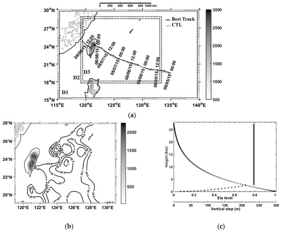
Figure 1.
(a) Best track of Typhoon Soudelor (black) from 5 August 00:00 UTC to 8 August 18:00 UTC in 6 h intervals, and the WRF (Weather Research and Forecasting) TC track (gray) from CTL from 5 August 00:00 UTC to 8 August 00:00 UTC in 1 h intervals. Dotted rectangles visualize parent and nested domains D1, D2 and D3 of the simulation. Shaded contours (every 500 m derived from 2 arc min gridded global relief data Etopo2) and the colorbar (m) display the Central Mountain Range heights. (b) Initial SST field (°C) on 5 August 00:00 UTC and terrain elevation (m) with 30 s resolution used for CTL. (c) Vertical distribution of 130 eta levels (circle) and corresponding vertical step height (plus) up to 27 km in the lower stratosphere (LS).
Then, hodographs of the horizontal wind perturbations were drawn as a function of altitude to identify elliptically polarized structures of low-frequency GWs in the troposphere and LS. The intrinsic frequency ω resulted from the axis ratio of the ellipse using the variance method of analysis, as described in Reference [24]. The one-dimensional fast Fourier transform (FFT) was used to characterize the vertical wavelength λv of the vertical profiles of the wind perturbations. The horizontal wavelength λh was estimated from the simplified dispersion relation of the GW linear theory described by the Equation (8.4.19) in Reference [47]:
where f is the inertial frequency.
The continuous wavelet transform (CWT) with the complex Morlet wavelet was used to analyze the time evolution of GW periods in the LS when TC Soudelor was approaching Taiwan. To focus on dominant GWs, spectral lines were derived from the CWT maxima. The method is detailed in Reference [48].
The combined conventional method (CCM) was based on two techniques commonly used to extract spectral characteristics of GW dominant modes from high-resolution radiosonde data: the SPARC (Stratosphere-troposphere processes and their role in climate) and the Stokes parameter methods [24]. Vertical profiles of temperature and wind were broken into parts to improve the extraction of perturbations and to avoid the detrending problem near the tropopause arising from strong changes in the temperature gradients.
In particular, a fraction of upward energy (Fup) > 50% (<50%) indicated that GWs with upward (downward) energy propagation were dominant. The degree of polarization (d) measured the ratio of completely polarized power to total power [45,49]. Thus, a value of 0% (100%) indicated a random or irregular (monochromatic) wave. A mean value >40% suggested a significant degree of polarization. Reference [50] reported the skill of the CCM to retrieve the spectral characteristics of a mesoscale GW from observation and simulation. Uncertainties in the horizontal wavelength, axis ratio, period and the direction of the horizontal wave propagation were lower than 20%, 10%, 10% and 15%, respectively.
In our study, they were applied on simulated vertical profiles of horizontal wind and temperature perturbations. The temperature was derived from the WRF prognostic variable of the potential temperature using the script built into NCAR Command Language (NCL) software.
3. Overview of TC Soudelor and Model Validation
3.1. Tropical Cyclone Soudelor (2015)
Tropical cyclone Soudelor was the most powerful TC in the 2015 Pacific typhoon season. It was formed near Pohnpei (6.8° N, 158.2° E) in the north–central tropical Pacific on 29 July 2015. Soudelor was classified as a Category 1 TC (Vmax < 33 m/s) on the Saffir-Simpson hurricane wind scale on 31 July 2015. It underwent rapid intensification on 2 August 2015 and made landfall on Saipan (15.2° N, 147.5° E) in the Northern Mariana Islands on 3 August. The intensity increased to Category 5 (Vmax > 70 m/s) at 15:00 UTC on Monday, 3 August. The 10 min (1 min) maximum sustained winds and minimum central pressure peaked at about 60 m/s (80 m/s) and 910 hPa, respectively (Figure 2a). Soudelor underwent an eyewall replacement cycle (ERC) with steady weakening from 4 August until its re-intensification above warmer waters with SST and OHC values > 30 °C and 75 kJ/cm2, respectively (refer to the Regional and Mesoscale Meteorology Branch products), at longitudes between 124° E and 126° E when it was approaching Taiwan late on 6 August. At 03:00 UTC on Friday, 7 August, the intense TC reached 1 min maximum sustained winds of about 50 m/s with wind gusts around 67 m/s when moving west–north–west at a speed of 5.1 m/s toward Taiwan (24° N, 121.6° E). A second ERC was undergone during the re-intensification stage from 6 August before the Category 3 TC (Vmax < 50 m/s) landfall over Xiulin, Hualien in Taiwan at 20:40 UTC (04:40 LST on 8 August). Indeed, the World Wide Lightning Location Network Tropical Cyclone (WWLLN-TC) observations supported the occurrence of an ERC with peaks of lightning strokes within 100 km (1000 km) of the TC center on 3 August (6 August). After crossing the Taiwan Strait from Taixi, Yunlin in Taiwan, the Category 1 TC made a new landfall over Mainland China around 14:10 UTC on 8 August and quickly downgraded inland from 9 August. It totally dissipated near Jeju Island (33.5° N, 126.5° E) on 13 August.

Figure 2.
(a) Time evolution of minimum central pressure (black) and 1 min sustained wind (red) of TC Soudelor from 30 July 2015 00:00 UTC to 9 August 2015 12:00 UTC, derived from best track observations. (b) Estimated total rainfall from 4 August 06:00 UTC to 9 August 18:00 UTC, derived from Global Precipitation Measurement (produced by H. F. Pierce from SSAI/NASA/JAXA).
The Central Mountain Range (CMR), with an average elevation of about 2000 m, modified the TC track [51,52,53] causing a slight northward deflection prior to landfall and a fairly substantial southward deflection from 8 August 00:00 UTC above the CMR. It also caused a north-west deflection after 06:00 UTC (Figure 1a). About 31% of the landfall typhoon pathways over Taiwan from 1981 to 2015 were similar to the one of TC Soudelor [54].
Heavy rains were unleashed from late on 6 August until early on 8 August, when the TC was above the Taiwan Strait (Figure 2b). A rainfall asymmetry was observed on the right side of the TC over warmer waters on 7 August. Radar observation visualized the time evolution of the surface TC structure, such as the breakdown of the inner core (Figure 3), as a response to the landfall over the island and the formation of a mesoscale secondary low center on the lee side of the southern CMR at about 23:10 UTC. The circular central core became elongated near the eastern Taiwanese coast accompanied by extremely heavy rain funneling into the far north of Taiwan. Meteorological stations reported light rain < 2.5 mm/h at Hualien (24° N, 121.6° E) at 12:00 UTC on 7 August and violent rain of 53.5 mm/h at 22:00 UTC on 7 August. When the mesoscale’s low center was formed, precipitation decreased quickly in Northern Taiwan to increase in the southern part (see Figure 4 in reference [55]). Large maximum 24 h rainfall of 1042 mm was observed from 7 July 12:00 UTC to 8 July 12:00 UTC over Northern Taiwan during TC Soudelor.
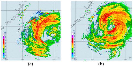
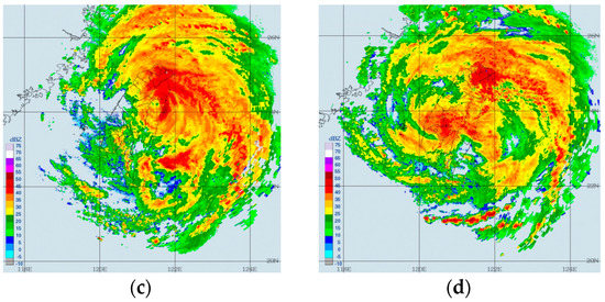
Figure 3.
Radar reflectivity (dBZ) derived from the Central Weather Bureau (CWB) Doppler radar network on 7 August at (a) 12:00 UTC, (b) 18:00 UTC, (c) 20:40 UTC and (d) 23:10 UTC, during landfall.
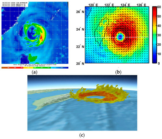
Figure 4.
(a) Brightness temperature on 7 August 13:00 UTC (from the U.S. Naval Research Laboratory database). (b) WRF simulated wind speed (m/s) at height of 4 km with horizontal wind vectors (black) on 7 August 12:00 UTC. The white dotted line crosses the TC center at latitude of 23° N. (c) Isosurfaces of wind speed of 60 m/s (yellow) and 75 m/s (red) on 7 August 12:00 UTC using Weather 3D software (Supplementary Materials).
3.2. Model Validation
The track of simulated TC Soudelor, derived from minimum sea level pressure in the inner core from D1 and D2 outputs respectively before and after 5 August 10:00 UTC, was compared with the observed track (hereafter called best track). The tracks mostly agreed from 5 August 12:00 UTC until 7 August 18:00 UTC with less than a three-hour delay before landfall when the TC was located at a distance <150 km of the eastern coast of Taiwan (Figure 1a). The slight northward deflection was well simulated after 12:00 UTC on 7 August prior to landfall. As a response to the topographic blocking, a southward deflection was then observed in the simulation from 8 August 00:00 UTC, but earlier than the observation and off the eastern coast of Taiwan. The simulation also showed realistic TC displacement speed and intensity until 18:00 UTC in comparison with observations (Figure 2a). On 7 August 12:00 UTC, when the outer spiral rainbands began to interact with the orography (Figure 3a), observations indicated a minimum pressure of 942 mb (±3 mb) and a maximum wind of 51.5 m/s (±4 m/s), in comparison with the respective simulated values of 940 hPa and 53.5 m/s for the domain D1, 943 hPa and 53.7 m/s for the domain D2, and 942 mb and 54 m/s for the domain D3. The interaction increased quickly a few hours later, in the afternoon, causing a decrease in the TC intensity. Indeed, an increase in the simulated maximum wind from 49.7 m/s to 57.9 m/s occurred from 6 August 00:00 UTC to 7 August 06:00 UTC and it was followed by a decrease in maximum wind to 53.3 m/s at 18:00 UTC. A mean value of about 53.2 m/s was estimated from 6 August 00:00 UTC to 7 August 18:00 UTC. In addition, the TC timing was fairly good, with errors <3 h (distance errors <55 km) ahead of time from 7 August 06:00 UTC. Indeed, timing and distance errors remained a challenging task prior to landfall especially beyond the 48-h integration period [56,57,58].
Satellite images clearly captured the TC asymmetry and the ERC from 5 August to 7 August. Figure 4a shows evidence of the asymmetry in brightness and temperature on 7 August 13:00 UTC, mostly located at the right rear side of the TC inner core. It was accompanied by a WN1 asymmetry in the simulated wind speed field of the TC inner core at the height of 4 km at 12:00 UTC on 7 August (Figure 4b). Wind speeds >60 m/s were located on the right side of the vortex above warmer waters (Figure 1b). The isosurfaces of the wind speeds of 60 m/s and 75 m/s provided a full view of both the horizontal and vertical distributions of the wind asymmetry (Figure 4c). High values of wind speed, >75 m/s, at heights <4 km in the TC eyewall, highlighted the asymmetry on 7 August 12:00 UTC. The simulated cumulative rainfall from 6 August 00:00 UTC to 8 August 00:00 UTC revealed high values from late on 6 August during the re-intensification with maximum values early on 7 August over the ocean (Figure 5a). The rainfall asymmetry was more pronounced on the right side of the TC from 7 August 12:00 UTC. Similar patterns and consistent rainfall intensity were derived from the Global Precipitation Measurement (GPM) over the ocean (Figure 2b). However, the GPM observation revealed a larger footprint of total rainfall as well as intense rainfalls close to the eye late on 6 August and midday on 7 August. Indeed, the GPM product reconstructed the precipitation with nearly 62% accuracy, with an overestimation that gradually decreased away from the TC center [59]. Compared with the observed 24 h rainfall (Figure 4 in Reference [55]) from 7 August 12:00 UTC to 8 August 12:00 UTC, the spatial rainfall distribution was well simulated above the CMR (Figure 5b).
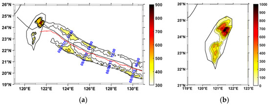
Figure 5.
(a) Cumulative rainfall (mm) from 6 August 00:00 UTC to 8 August 00:00 UTC from WRF outputs. The solid black (red) line displays the best (WRF) track. (b) A close up, from Image a), of Taiwan.
Figure 6 shows the vertical cross sections of tangential and radial wind speed, equivalent potential temperature and temperature anomalies with respect to a TC-unperturbed environment, on 7 August 12:00 UTC passing through the TC center at latitude 23° N (Figure 4b). This provided insight into a realistic structure of a mature TC as previously described in References [28,60]. Figure 6a visualizes the primary TC circulation with increasing radius of maximum winds (RMW) with height in agreement with the eyewall slopes radially outward height. The isocontours of 60 m/s bordered the intense wind core from the ground to about a height of 5 km (3 km) on the eastern (western) side and highlighted the wind asymmetry with height, especially above 3 km. Large wind speeds, >80 m/s, were mostly located on the eastern side at about 1 km above the surface. The freezing levels of the TC-unperturbed environment and those above the TC eye agreed with climatological monthly values over Taiwan during the TC season [61] and those in the TC inner core [60], respectively. The simulation also indicated that both the freezing level and the tropopause height were affected by the topography. Tangential wind speed of 40 m/s can be visualized up to about a 14 km height below the tropopause at about longitude 124.5° E. The cross section of radial wind showed the asymmetric low-level inflows in the PBL and upper-level outflows below the tropopause (Figure 6b). At 12:00 UTC, the topography affected the low-level inflow and upper tropospheric outflow ahead of the TC. Near the eyewall region, equivalent potential temperature θe (Figure 6c) depicted the divergent, slantwise, moist isentrope slope, the strong gradient in the eyewall and at the top of the marine PBL, the high values in the TC eye in the PBL, the descent of dry air into the TC eye and along the outer side of the eyewall, and the warm and dry central core at about a 5 km height [28,60,62]. The vertical cross section of temperature anomalies, beyond the longitude 123.2° east of the TC eye, revealed the presence of a double warm core with maxima of +9 K and +7 K at heights of about 4–5 km and 14 km, respectively (Figure 6d). The second warm core had a similar amplitude, but located about 1.5 km higher at 00:00 UTC. The observation of the two warm anomalies in the troposphere within a radius of 75–100 km was consistent with previous studies on relatively intense TCs [63,64]. Reference [65] described the formation of an upper-level warm core from the subsidence of stratospheric air into the eye, which coincided with the onset of the rapid intensification of TC Wilma (2005). Reference [66] argued that the location of warm cores is dependent on the vertical profiles of static stability and mean descent. The double warm core of intense simulated TCs, is usually accompanied by a thin upper-level inflow layer in the LS above the typical upper outflow layer (Figure 6b), which can advect potentially warm air from the LS (Figure 6d) toward the inner core region [64]. Reference [67] concluded that such interactions of intense TCs with the LS are responsible for the presence of the upper-level warm anomaly and possible episodes of TC intensification. At present, the dynamics of a double warm core and its relationship with TC intensity as well as intensity change still need to be explored [65,66]. Radar reflectivity isocontours of 20 dBZ and 40 dBZ also show the footprint of the TC asymmetry in rainfall, as well as intense rainfall in the inner core at heights below the freezing level and a rapid decrease in reflectivity across the freezing level indicative of intense melting (not shown). The asymmetry increased as the interaction between the orography and the TC outer core became stronger, in the time before landfall.
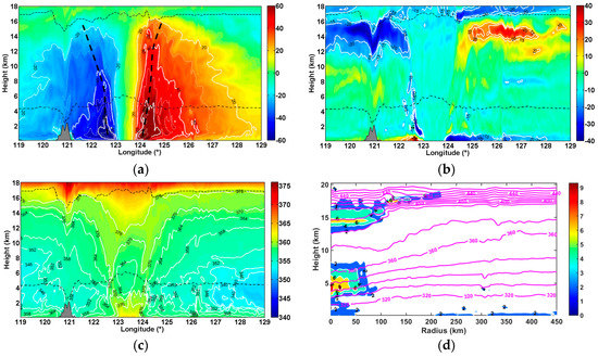
Figure 6.
Longitude-height cross sections of simulated (a) tangential wind speed (m/s) and isocontours (white) every 10 m/s, (b) radial wind speed (m/s) and isocontours (white) of ±15 and 20 m/s, (c) equivalent potential temperature θe (K) and isocontours (white) every 6 K at the latitude 23° N on 7 August 12:00 UTC. (d) Radial-height cross section of temperature anomalies (color shaded, K) and isocontours (white) every 2 K east of the TC center. Isocontours of potential temperature every 10 K are superimposed (magenta). Horizontal dash-dotted and dashed lines denote the distribution of the freezing level (0 °C isotherm) and the thermal tropopause. Thick vertical dashed lines locate the radius of maximum wind. The orography of Taiwan is shaded grey.
FormoSat-3/COSMIC RO data are useful for observations of TC events above the ocean as well as the validation of numerical simulations [20,68,69,70,71]. Vertical profiles of temperature are accurate at <1 K from 5 to 25 km and spatial resolution varyies from 100 m at the surface up to 1.4 km at 40 km heights (1 km at the altitude of tropopause). Figure 7a visualizes the geographic distribution of 13 available FormoSat-3/COSMIC RO profiles during the passage of TC Soudelor at latitudes of 20°–28° N and longitudes of 119°–130° E on 6 and 7 August 2015. The TC eye was located at the lower right corner of the domain at 00:00 UTC on August 6. In particular, four soundings probed the inner and outer TC core when TC Soudelor was at a distance <400 km off the coast of Taiwan at about 08:30 UTC on 7 August 2015. Potential temperatures with 100 m vertical resolution were computed from the «wetPrf» FormoSat-3/COSMIC RO profiles of temperature and pressure, and the vertical background was derived using a fourth-order low-pass Butterworth filter with a 7 km vertical wavelength cutoff. The mean WRF profiles of potential temperature within 1° × 1° area were compared with the collocated FormoSat-3/COSMIC RO profile. Absolute differences in mean potential temperatures were <±4 K in the troposphere at heights <16 km. The amount of water vapor was partly responsible for the large differences in temperature in the lower and middle troposphere. Concerning the LS, large absolute deviations above 22 km height were presumably caused by the top lateral boundary conditions imposed by the NCEP FNL 6-hourly analyses. Indeed, the gradient of NCEP FNL potential temperature was slightly smaller than the WRF one above 19 km height. However, the mean potential temperatures were satisfactorily in agreement at heights <25 km with a small relative bias <3%. In this study, the mean profile of FormoSat-3/COSMIC RO potential temperature (Figure 7b) was used to compute the Brunt-Väisäla frequency N in Equation (1). The mean observational values were 1.23 × 10⁻² s−1, 0.8 × 10⁻² s−1 and 2.43 × 10⁻² s−1 at heights of 3–10 km, 8–15 km and 18–25 km, respectively.
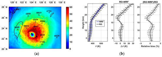
Figure 7.
(a) Distribution of FormoSat-3/COSMIC (Formosa Satellite Mission-3/Constellation Observing System for Meteorology, Ionosphere, and Climate) RO (radio occultation) data on 6 and 7 August 2015 (triangle and plus sign, respectively) superimposed on horizontal cross section of WRF simulated wind speed (m/s) at a 4 km height on 7 August 0830 UTC. Labels (black) indicate the time in UTC of soundings. Black dots visualize TC Soudelor’s best track at 06:00 and 12:00 UTC. (b) Mean profiles of potential temperature and standard deviation (multiplied by 10) at geographical location of COSMIC RO soundings derived from COSMIC RO and WRF data (left), corresponding absolute differences and standard deviation in mean potential temperature (middle), and relative bias (right).
Finally, the model reasonably reproduces the dynamical structure of a realistic mature TC as well as its global environment at heights up to 25 km at latitudes of 20°–28° N and longitudes of 119°–130° E on 6 and 7 August prior to landfall. The effects of the topography on the TC structure were weak on 7 August 12:00 UTC when the TC was at a distance <200 km from the eastern coast of Taiwan. Thus, taking into account the description of the dynamic and thermodynamic structures of TC Soudelor at 12:00 UTC on 7 August, GWs with vertical wavelengths <7 km were examined at three different vertical layers: the middle of the TC (3–10 km), the upper part of the TC (8–15 km) in the troposphere and LS (18–25 km).
4. Results
The analyses of ECMWF (European Centre for Medium-Range Weather Forecasts) revealed a strong TC on 7 August 2015 prior to landfall over Taiwan. Indeed, Figure 7a in Reference [71] shows a compact TC structure with an elliptical shaped eye at a 4 km height on 7 August 12:00 UTC. The WN1 asymmetry was reproduced on the right side of the TC but with intense wind, smaller size and closer to the TC center in comparison with Figure 4b. In contrast, the size of the structure, circular shaped eye and WN1 wind asymmetry were reasonably captured by NCEP GFS (National Centers for Environmental Prediction Global Forecast System) analyses but with less intense wind speeds (not shown). Unlike NCEP GFS analyses, the isosurfaces of vertical velocity derived from the ECMWF analyses showed evidence of quasi-circularly stratospheric GWs with horizontal wavelengths between 100 km and 200 km in the UT and LS propagating upward in the stratosphere (Figure 7 in Reference [71]). Considering the observations mentioned above, NCEP GFS analyses were used to initialize a WRF-ARW model for the simulation of TC Soudelor and the generation of stratospheric TC-induced GWs as observed in the ECMWF operational analyses.
Indeed, the simulation revealed the presence of TC-induced wavelike patterns on horizontal cross sections of simulated vertical velocity in the troposphere and LS on 7 August 12:00 UTC (Figure 8). It showed evidence of a mesoscale wavelike structure with a dominant horizontal wavelength of about 140 km in Region A at the rear of TC Soudelor at 20 km height in the LS (Figure 8a) and fine-scale structures with horizontal wavelength of about 20 km in Regions B and C at a 12 km height in the UT (Figure 8b). The latter ones were located above intense convection in the spiral rainbands. In addition, the filtered field of vertical velocity in the Region D of the domain D1 (Figure 8c) also depicted a mesoscale semi-circular GW structure in the LS with a horizontal wavelength of about 200 km. Indeed, the application of the FFT on the simulated vertical velocity perturbations at the latitude 23° N supported the presence of dominant wavelike structures with horizontal wavelengths of 150–250 km at 20 km height in the LS. Structures with long horizontal wavelengths of 400–600 km are also found as observed in references [20,72].
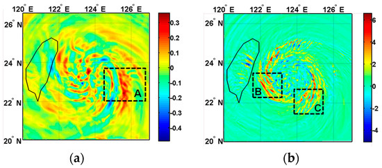
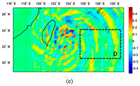
Figure 8.
Horizontal cross sections of simulated vertical velocity (m/s) in the domain D3 with horizontal resolution of 3 km at (a) 20 km height and (b) 12 km height on 7 August 12:00 UTC. Same as Figure 8a, but in the domain D1 with horizontal resolution of 27 km (c) at 25 km height. Regions A, B, C and D highlight wavelike structures of GWs.
Figure 9a,c,e display the horizontal distributions of mean wave energy density at 12:00 UTC on 7 August, for vertical layers of 3–10 km, 8–15 km and 18–25 km, respectively. The value of Ew was small in comparison with those computed with horizontal wind perturbations and, consequently, it was neglected in the calculation of the total kinetic energy density. At heights of 3–10 km, GW energy density was observed to be mainly imbedded within the eyewall and spiral rain bands (Figure 9a). The longitudinal cross-section at latitude 23° N revealed the dominance of Ek in Et and an asymmetry at longitudes between 124° E and 128° E at the rear of the TC with peaks of intensity in the eyewall (Figure 9b). The asymmetry was strengthened by the orography at 12:00 UTC. The asymmetry in Ek and Ep was clearly visualized in the UT (Figure 9c,d) and LS (Figure 9e,f). In addition, the activity of energy density spread outward along the eyewall and Ep became large and dominant in the UT. In particular, a significant activity of Ep was observed above the CMR. A comparison between Figure 9c,e revealed different distributions of wave energy density. The maximum wave energy density was mostly localized at a longitude of about 124.5° E and 23.5° N in the LS above the location of the RMW in the UT (Figure 9e,f, respectively). The values of the mean total energy density Et over the domain D2 were estimated at about 4.4 J kg−1, 13.36 J kg−1 and 10.3 J kg−1 at heights of 3–10 km, 8–15 km and 18–25 km, respectively. When the domain was divided into four sub-regions from the TC eye (23° N, 123.2° E), the values of Et were 6.4 J kg−1, 10.2 J kg−1, 10.6 J kg−1 and 5.3 J kg−1 for the upper left, upper right, lower right and lower left regions (hereafter called Regions 1, 2, 3 and 4, respectively) in the LS. Thus, larger values were observed at the rear of the TC (Regions 2 and 3) in the LS as well as in the UT. Figure 10 shows an example of vertical profiles of horizontal wind and temperature and perturbations in Region C. The sharp inversion of temperature near the tropopause biased somewhat the extraction of temperature perturbations at this altitude. Nevertheless, the superposition of raw and mean profiles showed evidence of wavelike structures with a vertical wavelength of about 1.5–2.5 km (3.5 km) below (above) 10 km height (Figure 10a). In particular, large amplitudes of horizontal wind perturbations (>2 m/s) were observed in the UT and LS. In addition, temperature and zonal wind perturbations are in quadrature in the UT and LS, whereas temperature and meridional wind perturbations were out of phase (Figure 10b). Thus, the phase relationships between perturbations were in agreement with the linear theory of GW polarization, which sketched elliptically polarized structures on the hodograph of horizontal wind perturbations [24]. Indeed, the hodographic analysis confirmed the presence of elliptical structures of GWs at 12:00 UTC on 7 August. Significant amplitudes of horizontal wind perturbation were retrieved from 100 m interpolated vertical profiles of perturbations in Regions A, B, C and D (Figure 11). The variation of the axis ratio, vertical length of the ellipses and direction of the major axis indicated GWs of different natures. The axis ratios and perimeters of the two ellipses on Figure 11c,d indicated the presence of similar GWs with a vertical wavelength of about 2.6 km, but propagating southwestward and southeastward in Regions B and C, respectively, which was consistent with the direction of the wavelike patterns observed in Figure 8b. Figure 11e,d revealed some GWs with a vertical wavelength of about 2 km, which propagated northeastward and eastward at the upper border and within Region D, respectively. Such results supported the presence of the mesoscale semi-circular GWs propagating dominantly eastward at the rear of the TC. For these last cases, cyclonic rotation (anticyclonic) of the ellipse with height at altitudes <15 km (>15 km) indicated downward (upward) propagation of wave energy density in the troposphere (LS) and suggested the presence of a GW source located near the tropopause. Elliptically polarized structures of GWs were also observed ahead of TC Soudelor in the UT and LS above Taiwan when the TC was approaching the island as far as a distance of 1100 km from 6 August at 00:00 UTC (not shown). In comparison, Reference [12] reported TC-induced GWs on high-resolution radiosonde profiles in the UT and LS above Tromelin Island (16.1° S, 54.3° E) when TC Hudah (2000) at a distance less than 2000 km east. Besides, simulated profiles of horizontal wind perturbations revealed the presence of quasi-inertial GWs in the TC eye with large amplitudes of perturbations (Figure 12a,c) where the two warm anomalies were located at about 5 km and 15 km heights (Figure 6d). The inertial period was estimated at about 30.7 h at the latitude of the TC eye. Figure 12a indicates that the hodograph is cyclonic (anticyclonic) below (above) 5 km height. Similar observations were reported below and above 15 km height (Figure 12b,c). The two elliptically polarized GWs had the same intrinsic periods of about 20 h (ω/f ≈ 1.5). The vertical and horizontal wavelengths were estimated at about 1.4 km (2.6 km) and 254 km (328 km), respectively, in the lower troposphere (UT). A destructive interference between upward and downward inertio-GWs might explain the presence of an intermediate GW with an intrinsic period of about 10 h (ω/f ≈ 2.8), and horizontal and vertical wavelengths of about 150 km and 1.9 km respectively, located at heights of 6.5–10.5 km between the two anomalies. Reference [28] previously proposed a conceptual model of the TC inner core including GWs above the warmer core interacting with the weak subsidence in the eye and stronger descent at the inner edge of the eyewall. The FFT was applied on the vertical profiles of zonal and meridional wind perturbations at latitude of 23° N and longitudes between 119° E and 133° E to compute the energy distribution as a function of vertical wavelength for height layers of 3–10 km, 8–15 km and 18–25 km (Figure 13a). The energy density was normalized by the maximum value produced by zonal wind perturbations at heights of 8–15 km. Wave perturbations were dominant in the zonal wind, especially in the UT. The mean vertical wavelength peaked in both zonal and meridional wind perturbations at about 4 km in the UT and LS. It was shorter in the lower troposphere (2–4 km). The vertical profiles of intrinsic frequencies ω derived from the method of variance and were calculated at 3–25 km heights and latitude 23° N. Figure 13b visualizes the mean longitude–height distribution of the normalized intrinsic frequencies ω/f at longitudes between 119° E and 129° E. The analysis captured low-frequency GWs with normalized intrinsic frequencies up to 6 (period of 5 h) with a mean value of 2.5–3.5 (periods of 8–13 h). Large normalized intrinsic frequencies were mostly localized at the rear of the TC. They were mostly present from the bottom up to heights of 10–11 km and also below the tropopause where the TC outflows are located. Finally, the observations identified the tangential wind asymmetry below the tropopause as possible locations of GW sources. Figure 13c indicates that the mean value of normalized intrinsic frequencies decreased from 4.6 (T = 7 h) in the lowest level at 2 km height to 2.8 (T = 12 h) at about 12 km height and ranged between 2.4 and 3 (T = 10–13 h) in the UT and LS. The occurrence distributions of periods, normalized by the maximum value at heights of 3–25 km, highlighted weighted mean values ranging between 12.5 h and 14.5 h for the three height layers with a mean value of 13.4 h for the layer of 3–25 km (Figure 13d). Structures with short periods <5 h were dominant at heights <10 km. In comparison, the observations of TC Ivan (2008) revealed dominant low-frequency GWs with periods of 4 h and 6–8 h in the UT and longer periods of 13 h in the LS and the simulation produced GWs with periods of 4–12 h during TC intensification in the UT and LS. Considering the respective dominant parameters λv and ω/f of 2–5 km and 2.5–3.7 (periods of 9–13 h) at 5–25 km heights. Equation (2) provided dominant horizontal wavelengths of 116–708 km in the troposphere and LS.
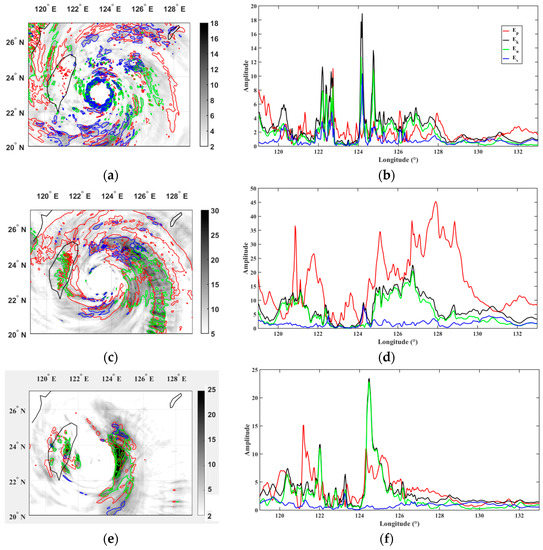
Figure 9.
Mean kinetic energy distribution Ek (J kg−1) from horizontal wind perturbations (grey shading) at heights of (a) 3–10 km, (c) 8–15 km and (e) 18–25 km on 7 August 12:00 UTC. Contours of mean energy density (J kg−1) derived from potential temperature (Ep, red), zonal wind (Eu, green) and meridional (Ev, blue) perturbations are superimposed. Longitudinal cross-sections of mean energy density distributions: (b) 3–10 km, (d) 8–15 km and (f) 18–25 km at latitude 23° N.
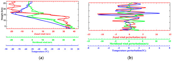
Figure 10.
(a) Vertical profiles of zonal (solid red) and meridional wind (solid green), and temperature (solid blue) at location (22° N, 124.3° E) in region C. Mean vertical profiles (dash-dotted) are retrieved using a fourth-order Butterworth low-pass filter with a 7 km wavelength cutoff. (b) Temperature and horizontal wind perturbations.
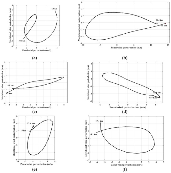
Figure 11.
Hodographs of horizontal wind perturbations on 7 August 12:00 UTC. In the LS (a) at (23° N, 125° E) in the UT and (b) at (22° N, 126.4° E) in Region A; in the middle troposphere (c) at (23° N, 122° E) in Region B, (d) at (22° N, 124.9° E) in Region C; (e) at (25.5° N, 125.3° E) and (f) at (21° N, 128.8° E) in the UT in Region D respectively. Crosses visualize the vertical step of 100 m height. Regions A, B, C and D are drawn on the Figure 8.
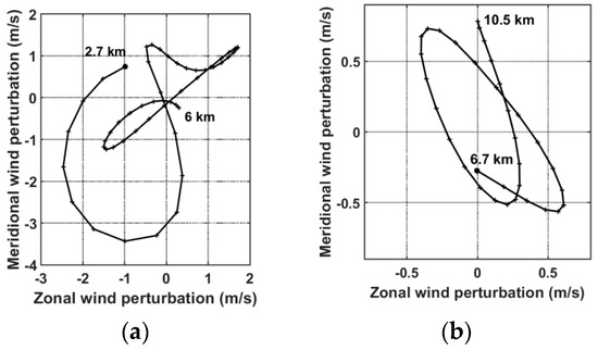
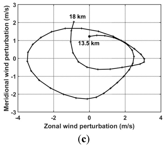
Figure 12.
(a), (b) and (c) similar as Figure 11 but in the TC eye (23° N, 123.2° E).
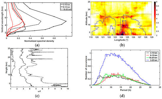
Figure 13.
(a) Normalized-spectral energy distribution of vertical wavelengths at heights of 3–10 km (solid), 8–15 km (plus) and 18–25 km (dash-dot) in zonal (black) and meridional (red) wind perturbations at latitude 23° N. (b) Longitude–altitude distribution of normalized intrinsic frequencies ω/f with contours of tangential wind (blue solid) and tropopause height (dashed) at latitude 23° N. (c) Normalized intrinsic frequencies ω/f (solid) and standard deviation (dashed) as a function of altitude at latitude 23° N. (d) Normalized distributions of occurrence of periods at heights of 3–10 km, 8–15 km, 18–25 km and 3–25 km at latitude 23° N.
The CWT was applied on a 6 min time series of normalized dynamical parameters (zonal, meridional and vertical wind) above two sites located at the same latitude (124° E, 24.3° N) and (131.2° E, 24.3° N), respectively, ahead and at the rear of the TC in the LS (20 km height) during the passage of TC Soudelor in the domain D3 during the 24 h period from 6 August 18:00 UTC to 7 August 18:00 UTC. The vertical wind perturbations were extracted by removing the constant trend from the time series. Then, the spectral lines, with values >20% of the maximum value, were derived from the CWT maxima to highlight the time evolution of dominant periods. In particular, they showed evidence of a dominant wavelike structure with periods of 9–14 h in the perturbations above the two sites (Figure 14). The analyses also depicted wavelike structures with periods of 3–7 h. In particular, transient high-frequency modes with period < 1 h are clearly observed ahead of the TC in vertical wind perturbations on 7 August from 04:00 UTC during the intensification phase (Figure 14b). Reference [73] suggested that momentum flux for GWs with frequencies of 0.3–2 h produced by TC Saomai (2006) might have significantly affected the TC development. Figure 14a,b,d also visualizes a discontinuity at about 10:00 UTC–12:00 UTC in the time evolution of mode of 6 h period when TC Soudelor started to interact with the island and the TC intensity decreased.
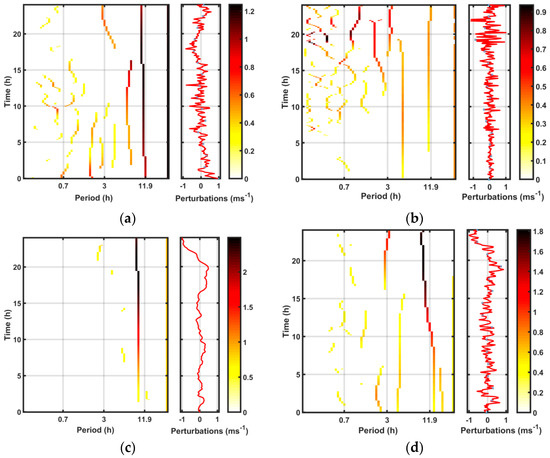
Figure 14.
Time evolution of dominant periods (right) derived from the CWT spectral lines of normalized wind perturbations (left) located ahead of the TC (124° E, 24.3° N) at 20 km height for (a) zonal wind and (b) vertical wind. Part (c) and (d) are the same as Figure 14a,b but at the rear of the TC (131.2° E, 24.3° N). Time starts from 6 August 18:00 UTC and ends on 7 August 18:00 UTC.
The CCM was applied to the simulated vertical profiles of wind and temperature perturbations in different regions of the domain D1 to characterize the elliptical structures of dominant GWs (Table 1). A regular spatial sampling at every 0.5° × 0.5° provided 196 vertical profiles in the domain 0 (20°–26° N; 120°–172° E) centered on the location of the TC eye (23° N, 123.2° E) at 12:00 UTC on 7 August. The fraction of upward energy Fup, the degree of polarization d and the direction of the horizontal wave propagation Phi indicated mixed upward and downward GWs with short vertical and horizontal wavelengths of 1.6 km and 31 km, respectively, and a period of about 2 h propagated westward in the UT. In opposition, GWs were more polarized in the LS with dominant upward wave energy. They had longer vertical and horizontal wavelengths of 3.5 km and 250 km, respectively, and a period of about 6 h with eastward propagation. Then, characteristics of GWs were examined in the four equal sub-regions of the domain 0 from the TC eye (23° N, 123.2° E): 1(upper left), 2 (upper right), 3 (lower right) and 4 (lower left). Structures of GWs with westward propagation were more polarized on the right side of the TC above Regions 1 and 2 in the UT. In contrast, GWs mostly propagated eastward above Region 3 in the UT. Modes with short vertical wavelengths of about 1.5 km were present in front of the TC in the UT and LS in Region 1. Periods of GWs varied between 4.8 h and 7.4 h and the direction of horizontal wave propagation was north-eastward and south-eastward in the right side (Regions 1 and 2) and left side (Regions 3 and 4), respectively, in the LS. The degree of polarization and fraction of upward wave energy were both significant above Regions 2 and 3 at the rear of the TC. Vertical and horizontal wavelengths of 1.4–2 km (3.5 km) and 80–110 km (220–340 km) were globally retrieved in the UT (LS) above the four sub-regions. In Region A at heights of 8–15 km, south-eastward propagating GWs with short vertical wavelengths of 24 km were captured above the spiral rainbands. Modes with horizontal wavelengths of about 100–150 km were dominant in the troposphere and LS. The eastward phase propagation (ch = λh ω /2 π) was estimated at about 12 m/s in the LS. A significant fraction of upward wave energy and the degree of polarization were reported in the LS, especially at the rear of the TC. Quite similar results were produced with increased sampling in Region A. Indeed, Table 1 indicates that results vary little in the LS when 143 vertical profiles are used in comparison with those derived from 30 samples. Periods varied between 1.2 h and 6.7 h in the troposphere and LS. Closer to the TC eye, characteristics of GWs in Region C were in agreement with those in the Region A, except at heights of 3–10 km where GWs with a long horizontal wavelength and period of 310 km and 11 h were detected. The south-eastward propagation of short-scale waves in the UT was consistent with the observation on Figure 11d. In addition, GWs were highly polarized in the UT and LS, and both large values of Fup and d were calculated in the LS. In summary, GWs with vertical and horizontal wavelengths of 1.4–3.5 km and 24–150 km, respectively, periods of 1.2–6.7 h and westward horizontal propagation were globally observed in the troposphere whereas GWs with longer vertical and horizontal wavelengths of 3.5 km and 140–380 km, respectively, periods of 3.1–8.4 h propagated eastward in the LS. In particular, quasi-monochromatic GWs with upward wave energy and eastward direction of horizontal propagation were identified at the rear of the TC in the LS. The 6 h period mode was dominant in the UT and LS. Mesoscale GWs with a vertical wavelength of 3.5 km and longer wavelengths and periods of 420–640 km and 10–14 h, respectively, were also detected in the troposphere and LS. Vertical wavelengths of GWs were derived from observations using five COSMIC RO profiles of temperature early on 7 August from 07:51 UTC to 09:57 UTC. Figure 7a located the soundings and the simulated TC Soudelor at 08:30 UTC. The heights and temperatures of the tropopause were consistent with the location of COSMIC RO soundings near the TC eye, i.e., the lowest temperatures and highest altitudes were obtained by COSMIC RO soundings at 08:14 UTC, 09:57 UTC and 08:06 UTC (Figure 15a). Far from the right side of the TC at 07:51 UTC, colder temperatures at heights of 3-9 km and a lower tropopause were observed. In addition, the temperatures at the tropopause were significantly perturbed at the rear right side of the TC core at 08:06 UTC (Figure 15a). Globally, signatures of quasi-monochromatic wavelike patterns were evident on temperature profiles in the LS. A fourth-order low-pass Butterworth filter with a cutoff of 7 km was applied to the temperature profiles to retrieve the perturbations in the troposphere (2–15 km) and stratosphere (18–30 km). Large amplitudes of temperature perturbations >1° K were mainly observed at heights of 6–11 km and 18–26 km with dominant vertical wavelengths of 1–3 km and 2.5–4 km, respectively (Figure 15b). The FFT was applied to temperature perturbations to highlight vertical wavelengths of dominant GW modes. In the troposphere, GWs with short vertical wavelengths of 1.5–2.5 km were observed near TC inner core, more significant in front of the TC at 08:14 UTC with a vertical wavelength of about 1.5–2 km (Figure 15c). A dominant mode, with a vertical wavelength of about 3.5 km, was observed on profiles at latitudes between 22° N and 25° N. In contrast, the FFT of the perturbation profile at 07:51 UTC revealed two peaks at 2.5 km and about 5 km far north-east of the TC. As the vertical resolution of COSMIC RO temperature profiles varied between 1 km at the tropopause and 1.4 km at 40 km height, only GWs with vertical wavelengths >2.5 km could be properly analyzed at heights of 18–30 km. Figure 15d reveals dominant modes with vertical wavelengths of 3–5 km in the LS with a peak at the vertical wavelength of 3.5 km.

Table 1.
Characteristics of dominant GWs using combined conventional methods (CCM) on simulated vertical profiles of horizontal wind and temperature on 7 August 12:00 UTC. Values are derived from peaks of wave parameter distributions. Region: location of vertical profiles; heights: altitude range; number: number of extracted profiles; λv and λh: vertical and horizontal wavelengths; T: intrinsic period; Phi: direction of horizontal wave propagation (clockwise from north), Fup: fraction of upward energy; d: degree of polarization. Region 0 (20°–26° N; 120°–172° E) is divided into four sub-regions from the TC eye (23° N, 123.2° E): 1 (upper left), 2 (upper right), 3 (lower right) and 4 (lower left).
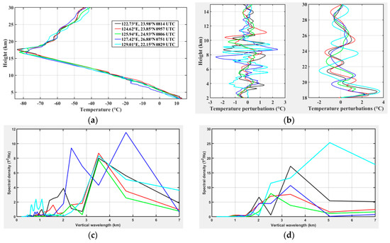
Figure 15.
(a) FormoSat-3/COSMIC RO profiles of temperature at heights of 3–30 km from 07:51 UTC to 09:57 UTC nearby the TC on 7 August 2015. (b) Perturbations in the troposphere (left) at 2–15 km and LS at 18–30 km (right). Part (c) and (d) correspond to spectral density as a function of vertical wavelength respectively. For all figures, refer to colors in the legend of Figure 5a for the date and location of the RO profiles and also Figure 7a for the spatial distribution.
5. Summary and Conclusions
A triple-nested model with horizontal resolutions of 27 km, 9 km and 3 km and vertical resolutions ≤250 m up to 27 km height enabled us to simulate a realistic dynamical structure of the mature TC Soudelor (2015) when it was approaching the Taiwanese eastern coast from early on 5 August to late on 7 August 2015. In particular, the TC track and its environment were simulated fairly, along with the intensity change from 6 August 00:00 UTC to 7 August 12:00 UTC. Prior to landfall over Taiwan, the TC structure was characterized by a WN1 wind asymmetry at the right rear of TC Soudelor and two warm temperature anomalies in the inner core during its passage over northern warmer water. The analysis methods focused on TC-induced GWs with vertical wavelengths <7 km. In the region of wind asymmetry, large values of kinetic GW energy density were located in the eyewall in the lower and middle troposphere at 12:00 UTC on 7 August while potential GW energy density was found significant in the UT and LS. With high-vertical resolution, the simulation provided the coupling between vertical and horizontal scales of GWs. Thus, the spectral characteristics of dominant GWs produced by TC Soudelor were examined in the UT and LS on 7 August 12:00 UTC. Indeed, elliptical structures of GWs of different natures were identified in the troposphere and LS during the evolution of TC Soudelor with dominant vertical wavelengths of about 1.5–2.5 km in the troposphere and 3.5 km in the LS, respectively. The 6 h period mode was dominant in the UT and LS. A mesoscale GW with a dominant horizontal wavelength ranging between 100 km and 300 km was identified at the rear of the TC in the UT and LS. High-frequency GWs were dominantly located in source regions, i.e., inside and above the wind asymmetry of the TC eyewall and below the tropopause above the TC core. Globally, the analysis revealed a large spectrum of GWs with horizontal wavelengths, vertical wavelengths, and periods with ranges of 16–900 km, 1.5–5 km, and 1–20 h, respectively. The mean period of inertia-GWs was about 8–13 h in the troposphere and LS. Dominant GWs propagated westward in the UT and eastward in the westward background stratospheric wind. In the TC eye, two quasi-diurnal GWs with short vertical wavelengths of 1.5–2.5 km and horizontal wavelengths of 250–350 km were produced at the location of the two warm anomalies in the TC inner core on 7 August 12:00 UTC. The two waves generated intermediate GWs with a semi-diurnal period and a horizontal wavelength of about 150 km in the middle troposphere. The analysis of the time series of wind perturbations highlighted dominant modes with periods of about 6–7 h and 9–14 h in the LS during the evolution of TC Soudelor and transient high-frequency modes with periods <1 h ahead of the TC in vertical wind during the intensification phase. This study revealed that the time evolution of the different modes might contain information about changes in the TC dynamics. The analysis of COSMIC RO observations also highlighted a broad GW spectrum of vertical wavelengths between 2 and 5 km in the troposphere and LS as well as dominant vertical wavelengths of about 3.5 km in the UT and LS.
Previous results have reported similar GW characteristics during stages of TCs. Significant mesoscale TC-induced GWs with horizontal wavelengths of 100–600 km propagating eastward were identified in the LS independently of the background stratospheric wind [17,20,74,75,76]. Indeed, several studies have exhibited low-frequency dominant modes with periods of 2–15 h [72,74,75,76] and vertical wavelengths of 2–4 km [75,77,78]. In particular, the MU radar observation of TC 8719 (1987) revealed prominent GWs with vertical wavelengths of 2–4 km and periods of 5 h below the layer of temperature inversion at 9 km height and 15 h above 13 km height [79]. The mean period of inertia-GWs was about 11–13 h in the troposphere and LS. With similar observation [78], two quasi-monochromatic mesoscale GWs with periods of about 6–9 h and varying horizontal and vertical wavelengths of 300 km (600 km) and 3 km (6 km) were captured before (after) the passage of TC Kelly (1987). In addition, earlier overflights of a tropical cyclone during the Stratosphere-Troposphere Exchange Project (STEP) identified two mesoscales GW structures, propagating upward and eastward, with horizontal wavelengths of about 110 km and 250 km and periods of 6 h over the cloud shield in the UT and LS [74]. The mechanism of convective ‘mountains’ was revealed to be in agreement with the generation of such GWs. Reference [76] derived eastward propagating mesoscale GWs with horizontal and vertical wavelengths of 100–700 km and 3–7 km, respectively, from the simulation of TC Ewiniar (2006). The dominant vertical wavelength and period were about 3 km and 6 h, respectively, during the mature stage of the TC. Previously, Reference [72] simulated GWs with horizontal wavelengths of 300–600 km, periods of 6–11 h, and vertical wavelengths of 3–11 km produced by TC Rusa (2002). In addition, the simulated TC Matsa (2005) also supported the generation of eastward propagating GW modes with periods of 12–18 h but with longer horizontal wavelength of about 1000 km in the LS [18] as observed during TC Hudah in 2000 [12]. High-frequency GWs, with periods <2 h, horizontal wavelengths of 15–300 km and vertical wavelengths of 2.5–8 km, were also found in observation and simulation [16,18]. More recently, the WACCM (Whole Atmosphere Community Climate Model) model showed that resolved TC-induced GWs can penetrate into the upper atmosphere [80]. Modes with short (<300 km), medium (300–600 km), and long (>600 km) wavelengths might contribute more than 40%, 30%, and 15% of the total zonal momentum fluxes, respectively. To conclude, our study supports the notion that TCs are complex sources of multi-scale GWs in the troposphere and LS. A realistic description of the TC with high vertical resolution is now needed to properly characterize TC-induced GWs as well as sources and GW effects during the TC evolution. In particular, the WN1 wind asymmetry was found to be strongly associated with the production of mesoscale GWs in the LS [20] as well as the presence of GWs in the TC core [28,75]. Finally, our results supported that TC-induced GWs could be indicative of changes in TC dynamics [26].
Today, high-resolution observational data are needed to explore TC cores at fine scales and to validate recent realistic high-resolution TC modelling. In this framework, FormoSat-3/COSMIC RO data may be an alternative means to cross-check the characteristics of GWs in the future studies as demonstrated in the current investigation. The follow-up mission of FormoSat-3/COSMIC, or FormoSat-7/COSMIC-2, is expected to be launched in 2019. Thus more COSMIC RO observations will be available to improve our knowledge of the TC inner core. In perspective, GW sources and momentum fluxes will be investigated.
Supplementary Materials
A 3D animation of the simulation from 6 August 18:00 UTC to 7 August 18:00 UTC 2015, produced by the Weather 3D software developed by Meteo-France, is available at https://www.youtube.com/watch?v=1aEDfNNqqWc.
Author Contributions
Conceptualization, F.C.M. and Y.-A.L.; methodology and software, F.C.M. and S.J.; validation and analysis, F.C.M.; HPC resources, F.C.M. and F.J.; writing–original draft preparation, F.C.M.; writing–review, F.C.M., S.J. and Y-A.L.; editing, F.C.M. and S.J.; supervision, F.C.M. and Y.-A.L.; funding acquisition, F.C.M., F.J. and Y.-A.L.; 3D visualization software and in-situ data provider: D.M. and J.-S.H.
Acknowledgments
This work was financially supported by grants from the ANRT (CIFRE 2015/0876), French ANR (BOOST3R ANR-17-CE01-0016-01) and Taiwanese MOST (105-2221-E-008-056-MY3, 107-2111-M-008-036). It was performed using HPC resources from GENCI-[TGCC/CINES/IDRIS] (Grant 2017 [A0010107689]) and the University of La Réunion. The WRF-ARW model and NCL software (http://dx.doi.org/10.5065/D6WD3XH5) were provided by the National Center for Atmospheric Research (NCAR). FormoSat-3/COSMIC RO data were obtained from CDAAC (COSMIC Data Analysis and Archive Center): http://cdaac-www.cosmic.ucar.edu. In-situ Taiwanese meteorological data were provided by the Central Weather Bureau.
Conflicts of Interest
The authors declare no conflict of interest. The founding sponsors had no role in the design of the study, the collection, analyses, or interpretation of data, the writing of the manuscript, or in the decision to publish the results.
References
- Smalley, K.M.; Dessler, A.E.; Bekki, S.; Deushi, M.; Marchand, M.; Morgenstern, O.; Plummer, D.A.; Shibata, K.; Yamashita, Y.; Zeng, G. Contribution of different processes to changes in tropical lower-stratospheric water vapor in chemistry-climate models. Atmos. Chem. Phys. 2017, 17, 8031–8044. [Google Scholar] [CrossRef]
- Podglajen, A.; Hertzog, A.; Plougonven, R.; Žagar, N. Assessment of the accuracy of (re)analyses in the equatorial lower stratosphere. J. Geophys. Res. 2014, 119, 166–188. [Google Scholar] [CrossRef]
- Butchart, N.; Cionni, I.; Eyring, V.; Shepherd, T.G.; Waugh, D.W.; Akiyoshi, H.; Tian, W. Chemistry-climate model simulations of twenty-first century stratospheric climate and circulation changes. J. Clim. 2010, 23, 5349–5374. [Google Scholar] [CrossRef]
- Garcia, R.R.; Smith, A.K.; Kinnison, D.E.; de la Cámara, Á.; Murphy, D.J. Modification of the gravity wave parameterization in the Whole Atmosphere Community Climate Model: Motivation and results. J. Atmos. Sci. 2017, 74, 275–291. [Google Scholar] [CrossRef]
- Yiğit, E.; Knížová, P.K.; Georgieva, K.; Ward, W. A review of vertical coupling in the Atmosphere–Ionosphere system: Effects of waves, sudden stratospheric warmings, space weather, and of solar activity. J. Atmos. Sol. Terr. Phys. 2016, 141, 1–12. [Google Scholar] [CrossRef]
- Liu, H.L.; McInerney, J.M.; Santos, S.; Lauritzen, P.H.; Taylor, M.A.; Pedatella, N.M. Gravity waves simulated by high-resolution Whole Atmosphere Community Climate Model. Geophys. Res. Lett. 2014, 41, 9106–9112. [Google Scholar] [CrossRef]
- De la Camara, A.; Lott, F.; Jewtoukoff, V.; Plougonven, R.; Hertzog, A. On the gravity wave forcing during the southern stratospheric final warming in LMDZ. J. Atmos. Sci. 2016, 73, 3213–3226. [Google Scholar] [CrossRef]
- Scinocca, J.F. An accurate spectral nonorographic gravity wave drag parameterization for general circulation models. J. Atmos. Sci. 2003, 60, 667–682. [Google Scholar] [CrossRef]
- McCormac, J.P.; Eckermann, S.D.; Hogan, T.F. Generation of a quasi-biennial oscillation in an NWP model using a stochastic gravity wave drag parameterization. Mon. Wea. Rev. 2015, 143, 2121–2147. [Google Scholar] [CrossRef]
- Fritts, D.C.; Alexander, M.J. Gravity wave dynamics and effects in the middle atmosphere. Rev. Geophys. 2003, 41, 1003. [Google Scholar] [CrossRef]
- Tsuda, T.; Nishida, M.; Rocken, C.; Ware, R.H. A global morphology of gravity wave activity in the stratosphere revealed by the GPS occultation data (GPS/MET). J. Geophys. Res. 2000, 105, 7257–7273. [Google Scholar] [CrossRef]
- Chane Ming, F.; Roff, G.; Robert, L.; Leveau, J. Gravity waves characteristic over Tromelin island during the passage of cyclone Hudah. Geophys. Res. Lett. 2002, 29, 1–4. [Google Scholar] [CrossRef]
- Liou, Y.A.; Pavelyev, A.G.; Wicker, J.; Liu, S.F.; Pavelyev, A.A.; Schmidt, T.; Igarashi, K. Application of GPS radio occultation method for observation of the internal waves in the atmosphere. J. Geophys. Res. 2006, 111, D06104. [Google Scholar] [CrossRef]
- Preusse, P.; Schroeder, S.; Hoffmann, L.; Ern, M.; Friedl-Vallon, F.; Ungermann, J.; Riese, M. New perspectives on gravity wave remote sensing by spaceborne infrared limb imaging. Atmos. Meas. Tech. 2009, 2, 299–311. [Google Scholar] [CrossRef]
- Meyer, C.I.; Ern, M.; Hoffmann, L.; Trinh, Q.T.; Alexander, M.J. Intercomparison of AIRS and HIRDLS stratospheric gravity wave observations. Atmos. Meas. Tech. 2018, 11, 215–232. [Google Scholar] [CrossRef]
- Kuester, M.A.; Alexander, M.J.; Ray, E.A. A model study of gravity waves over Hurricane Humberto (2001). J. Atmos. Sci. 2008, 65, 3231–3246. [Google Scholar] [CrossRef]
- Kim, S.Y.; Chun, H.Y. Stratospheric gravity waves generated by Typhoon Saomai (2006): Numerical modeling in a moving frame following the typhoon. J. Atmos. Sci. 2010, 67, 3617–3636. [Google Scholar] [CrossRef]
- Chen, D.; Chen, Z.Y.; Lü, D.R. Spatiotemporal spectrum and momentum flux of the stratospheric gravity waves generated by a typhoon. Sci. China: Earth Sci. 2012, 56, 54–62. [Google Scholar] [CrossRef]
- Preusse, P.; Ern, M.; Bechtold, P.; Eckermann, S.D.; Kalisch, S.; Trinh, Q.T.; Riese, M. Characteristics of gravity waves resolved by ECMWF. Atmos. Chem. Phys. 2014, 14, 10483–10508. [Google Scholar] [CrossRef]
- Chane Ming, F.; Ibrahim, C.; Barthe, C.; Jolivet, S.; Keckhut, P.; Liou, Y.A.; Kuleshov, Y. Observation and a numerical study of gravity waves during tropical cyclone Ivan (2008). Atmos. Chem. Phys. 2014, 14, 641–658. [Google Scholar] [CrossRef]
- Liou, Y.A.; Pavelyev, A.G.; Liu, S.F.; Pavelyev, A.A.; Yen, N.; Huang, C.Y.; Fong, C.J. FORMOSAT-3/COSMIC GPS radio occultation mission: Preliminary results. IEEE Trans. Geosci. Remote Sens. 2007, 45, 3813–3826. [Google Scholar] [CrossRef]
- Yu, D.; Xu, X.; Luo, J.; Li, J. On the relationship between gravity waves and tropopause height and temperature over the globe revealed by COSMIC radio occultation measurements. Atmosphere 2019, 10, 75. [Google Scholar] [CrossRef]
- Emanuel, K. 100 Years of Progress in Tropical Cyclone Research. Meteorol. Monogr. 2018, 59, 15.11–15.68. [Google Scholar] [CrossRef]
- Chane Ming, F.; Chen, Z.; Roux, F. Analysis of gravity waves produced by intense tropical cyclones. Ann. Geophys. 2010, 28, 531–547. [Google Scholar] [CrossRef]
- Ibrahim, C.; Chane-Ming, F.; Barthe, C.; Kuleshov, Y. Diagnosis of tropical cyclone activity through gravity wave energy density in the South West Indian Ocean. Geophys. Res. Lett. 2010, 37, L09807. [Google Scholar] [CrossRef]
- Hoffmann, L.; Wu, X.; Alexander, M.J. Satellite observations of stratospheric gravity waves associated with the intensification of tropical cyclones. Geophys. Res. Lett. 2018, 45, 1692–1700. [Google Scholar] [CrossRef]
- Nolan, D.S.; Zhang, J.A. Spiral gravity waves radiating from tropical cyclones. Geophys. Res. Lett. 2017, 44, 3924–3931. [Google Scholar] [CrossRef]
- Liu, Y.; Zhang, D.L.; Yau, M.K. A Multiscale numerical study of hurricane Andrew (1992). Part II: kinematics and inner-core Structures. Mon. Wea. Rev. 1999, 127, 2597–2616. [Google Scholar] [CrossRef]
- Chen, S.; Lu, Y.; Li, W.; Wen, Z. Identification and analysis of high-frequency oscillations in the eyewalls of tropical cyclones. Adv. Atmos. Sci. 2015, 32, 624–634. [Google Scholar] [CrossRef]
- Wu, L.; Braun, S.A. Effects of environmentally induced asymmetries on hurricane intensity: A numerical study. J. Atmos. Sci. 2004, 61, 3065–3081. [Google Scholar] [CrossRef]
- Kepert, D.J. Tropical Cyclone Structure and Dynamics. In Global Perspectives on Tropical Cyclones: From Science to Mitigation; Chan, J.C.L., Kepert, D.J., Eds.; World Scientific Publishing Company: Singapore, Singapore, 2010; pp. 3–53. [Google Scholar]
- Skamarock, W.C.; Klemp, J.B.; Dudhia, J.; Gill, D.O.; Barker, D.M.; Duda, M.G.; Powers, J.G. A description of the advanced research WRF version 3. In NCAR Technical Note; NCAR: Boulder, CO, USA, 2008. [Google Scholar]
- Kain, J.S. The Kain Fritsch Convective Parameterization: An Update. J. App. Meteor. 2004, 43, 170–181. [Google Scholar] [CrossRef]
- Hong, S.Y.; Noh, Y.; Dudhia, J. A new vertical diffusion package with an explicit treatment of entrainment processes. Mon. Wea. Rev. 2006, 134, 1318–1341. [Google Scholar] [CrossRef]
- Thompson, G.; Field, P.R.; Rasmussen, R.M.; Hall, W.D. Explicit forecasts of winter precipitation using an improved bulk microphysics scheme. Part II: Implementation of a new snow parameterization. Mon. Wea. Rev. 2008, 136, 5095–5115. [Google Scholar] [CrossRef]
- Mlawer, E.J.; Taubman, S.J.; Brown, P.D.; Iacono, M.J.; Clough, S.A. Radiative transfer for inhomogeneous atmospheres: RRTM, a validated correlated-k model for the longwave. J. Geophys. Res. 1997, 102, 16663–16682. [Google Scholar] [CrossRef]
- Dudhia, J. Numerical study of convection observed during the Winter Monsoon Experiment using a mesoscale two-dimensional model. J. Atmos. Sci. 1989, 46, 3077–3107. [Google Scholar] [CrossRef]
- Ma, L.M.; Bao, X.W. Parametrization of planetary boundary-layer height with helicity and verification with tropical cyclone prediction. Boundary Layer Meteorol. 2016, 160, 569–593. [Google Scholar] [CrossRef]
- Choudhury, D.; Das, S. The sensitivity to the microphysical schemes on the skill of forecasting the track and intensity of tropical cyclones using WRF-ARW model. J. Earth Syst. Sci. 2017, 126, 1–10. [Google Scholar] [CrossRef]
- Tao, W.K.; Shi, J.J.; Chen, S.; Lang, S.; Lin, P.L.; Hong, S.Y.; Hou, A. The impact of microphysical schemes on intensity and track of hurricane. Asia-Pacific J. Atmos. Sci. 2011, 47, 1–16. [Google Scholar] [CrossRef]
- Gopalakrishnan, S.G.; Goldenberg, S.; Quirino, T.; Zhang, X.; Marks, F.; Yeh, K.S.; Tallapragada, V. Toward improving high-resolution numerical hurricane forecasting: Influence of model horizontal grid resolution, initialization, and physics. Wea. Forecast. 2012, 27, 647–666. [Google Scholar] [CrossRef]
- Zhang, D.L.; Wang, X. Dependence of hurricane intensity and structures on vertical resolution and time-step size. Adv. Atmos. Sci. 2003, 20, 711–725. [Google Scholar] [CrossRef]
- Ma, Z.; Fei, J.; Huang, X.; Cheng, X. Sensitivity of tropical cyclone intensity and structure to vertical resolution in WRF. Asia-Pacific J. Atmos. Sci. 2012, 48, 67–81. [Google Scholar] [CrossRef]
- Fierro, A.O.; Rogers, R.F.; Marks, F.D.; Nolan, D.S. The Impact of horizontal grid spacing on the microphysical and kinematic structures of strong tropical cyclones simulated with the WRF-ARW model. Mon. Wea. Rev. 2009, 137, 3717–3743. [Google Scholar] [CrossRef]
- Vincent, R.A.; Allen, S.J.; Eckermann, S.D. Gravity wave parameters in the lower stratosphere. In Gravity Wave Processes: Their Parameterization in Global Climate Models; Hamilton, K., Ed.; Springer: New York, NY, USA, 1997; pp. 7–25. [Google Scholar]
- Sato, K.; Tateno, S.; Watanabe, S.; Kawatani, Y. Gravity wave characteristics in the Southern Hemisphere revealed by a high-resolution middle-atmosphere general circulation model. J. Atmos. Sci. 2012, 69, 1378–1396. [Google Scholar] [CrossRef]
- Gill, A.E. Atmosphere-Ocean Dynamics; Academic Press: London, UK, 1982; p. 259. [Google Scholar]
- Chane Ming, F.; Molinaro, F.; Leveau, J.; Keckhut, P.; Hauchecorne, A.; Godin, S. Vertical short-scale structures in the upper tropospheric-lower stratospheric temperature and ozone at la Réunion island (20.8° S, 55.3° E). J. Geophys. Res. 2000, 105, 26857–26870. [Google Scholar] [CrossRef]
- Lu, C.; Koch, S.E.; Wang, N. Stokes parameter analysis of a packet of turbulence-generating gravity waves. J. Geophys. Res. 2005, 110, D20105. [Google Scholar] [CrossRef]
- Chane Ming, F.; Vignelles, D.; Jegou, F.; Berthet, G.; Renard, J.B.; Gheusi, F.; Kuleshov, Y. Gravity-wave effects on tracer gases and stratospheric aerosol concentrations during the 2013 ChArMEx campaign. Atmos. Chem. Phys. 2016, 16, 8023–8042. [Google Scholar] [CrossRef]
- Lin, Y.L.; Witcraft, N.C.; Kuo, Y.H. Dynamics of track deflection associated with the passage of tropical cyclones over a mesoscale mountain. Mon. Wea. Rev. 2006, 13, 3509–3538. [Google Scholar] [CrossRef]
- Liu, L.; Lin, Y.L.; Chen, S.H. Effects of landfall location and approach angle of an idealized tropical cyclone over a long mountain range. Front. Earth Sci. 2016. [Google Scholar] [CrossRef]
- Wu, J.F.; Xue, X.H.; Hoffmann, L.; Dou, X.K.; Li, H.M.; Chen, T.D. A case study of typhoon-induced gravity waves and the orographic impacts related to Typhoon Mindulle (2004) over Taiwan. J. Geophys. Res. Atmos. 2015, 120, 9193–9207. [Google Scholar] [CrossRef]
- Chang, C.T.; Vadeboncoeur, M.A.; Lin, T.C. Resistance and resilience of social–ecological systems to recurrent typhoon disturbance on a subtropical island: Taiwan. Ecosphere 2018, 9, e02071. [Google Scholar] [CrossRef]
- Wu, M.C.; Hong, J.S.; Hsiao, L.F.; Hsu, L.H.; Wang, C.J. Effective use of ensemble numerical weather predictions in Taiwan by means of a SOM-based cluster analysis technique. Water 2017, 9, 836. [Google Scholar] [CrossRef]
- Mallik, M.A.K.; Ahasan, M.N.; Chowdhury, M.A.M. Simulation of track and landfall of tropical cyclone Viyaru and its associated strom surges using NWP models. Am. J. Mar. Sci. 2015, 3, 11–21. [Google Scholar]
- Mehra, A.; Tallapragada, V.; Zhang, Z.; Liu, B.; Zhu, L.; Wang, W.; Kim, H.S. Advancing the state of the art in operational tropical cyclone forecasting at NCEP. Trop. Cyclone Res. Rev. 2018, 7, 51–56. [Google Scholar]
- Mohapatra, M.; Nayak, D.P.; Sharma, M.; Sharma, R.P.; Bandyopadhyay, B.K. Evaluation of landfall forecast over North Indian Ocean issued by India Meteorological Department. J. Earth Syst. Sci. 2015, 124, 861–874. [Google Scholar] [CrossRef]
- Omranian, E.; Sharif, H.O.; Tavakoly, A.A. How well can global precipitation measurement (GPM) capture hurricanes? Case study: Hurricane Harvey. Remote Sens. 2018, 10, 1150. [Google Scholar] [CrossRef]
- Liu, Y.; Zhang, D.L.; Yau, M.K. A multiscale numerical study of Hurricane Andrew (1992). Part I: Explicit simulation and verification. Mon. Wea. Rev. 1997, 125, 3073–3093. [Google Scholar] [CrossRef]
- Jaiswal, R.S.; Fredrick, S.R.; Rasheed, M.; Neela, V.S.; Zaveri, L. Study of TRMM estimated freezing level height in the 36 N-36 S region. Indian J. Geo-Mar. Sci. 2015, 44, 1071–1095. [Google Scholar]
- Zhang, D.L.; Liu, Y.; Yau, M.K. A multiscale numerical study of Hurricane Andrew (1992). Part V: Inner-core thermodynamics. Mon. Wea. Rev. 2002, 130, 2745–2763. [Google Scholar] [CrossRef]
- Stern, D.P.; Nolan, D.S. On the height of the warm core in tropical cyclones. J. Atmos. Sci. 2012, 69, 1657–1680. [Google Scholar] [CrossRef]
- Kieu, C.Q.; Tallapragada, V.; Zhang, D.L.; Moon, Z. On the development of double warm-core structures in intense tropical cyclones. J. Atmos. Sci. 2016, 73, 4487–4506. [Google Scholar] [CrossRef]
- Zhang, D.L.; Chen, H. Importance of the upper-level warm core in the rapid intensification of a tropical cyclone. Geophys. Res. Lett. 2012, 39, L02806. [Google Scholar] [CrossRef]
- Stern, D.; Zhang, F. How does the eye warm? Part I: A potential temperature budget analysis of an idealized tropical cyclone. J. Atmos. Sci. 2013, 70, 73–89. [Google Scholar] [CrossRef]
- Moon, Z.; Kieu, C. Impacts of the lower stratosphere on the development of intense tropical cyclones. Atmosphere 2017, 8, 128. [Google Scholar] [CrossRef]
- Winterbottom, H.R.; Xiao, Q. An intercomparison of GPS RO retrievals with colocated analysis and in situ observations within tropical cyclones. Adv. Meteorol. 2010, 2010. [Google Scholar] [CrossRef]
- Vergados, P.; Luo, Z.J.; Emanuel, K.; Mannucci, A.J. Observational tests of hurricane intensity estimations using GPS radio occultations. J. Geophys. Res. Atmos. 2014, 119, 1936–1948. [Google Scholar] [CrossRef]
- Rivoire, L.; Birner, T.; Knaff, J. Evolution of the upper-level thermal structure in tropical cyclones. Geophys. Res. Lett. 2016, 43, 10530–10537. [Google Scholar] [CrossRef]
- Liou, Y.A.; Liu, J.C.; Chane Ming, F.; Hong, J.S.; Huang, C.Y.; Chiang, P.K.; Jolivet, S. Remote sensing of typhoons in the western Pacific Ocean. In Remote Sensing of the Asian Seas; Barale, V., Gade, M., Eds.; Springer: New York, NY, USA, 2019; pp. 251–267. [Google Scholar]
- Kim, S.Y.; Chun, H.Y.; Baik, J.J. A numerical study of gravity waves induced by convection associated with Typhoon Rusa. Geophys. Res. Lett. 2005, 32, L24816. [Google Scholar] [CrossRef]
- Kim, S.Y.; Chun, H.Y. Impact of typhoon-generated gravity waves in the typhoon development. Geophys. Res. Lett. 2011, 38, L01806. [Google Scholar] [CrossRef]
- Pfister, L.; Chan, K.R.; Bui, T.P.; Bowen, S.; Legg, M.; Gary, B.; Kelly, K.; Proffitt, M.; Starr, W. Gravity waves generated by a tropical cyclone during the STEP tropical field program: A Case Study. J. Geophys. Res. 1993, 98, 8611–8638. [Google Scholar] [CrossRef]
- Dhaka, S.K.; Takahashi, M.; Shibagaki, Y.; Yamanaka, M.D.; Fukao, S. Gravity wave generation in the lower stratosphere due to passage of the Typhoon 9426 (Orchid) observed by the MU radar at Shigaraki (34.85° N, 136.10° E). J. Geophys. Res. 2003, 108, 4595. [Google Scholar] [CrossRef]
- Kim, S.Y.; Chun, H.Y.; Wu, D.L. A study on stratospheric gravity waves generated by Typhoon Ewiniar: numerical simulations and satellite observations. J. Geophys. Res. 2009, 114, D22104. [Google Scholar] [CrossRef]
- Bindu, H.H.; Ratnam, M.V.; Yesubabu, V.; Rao, T.N.; Kesarkar, A.; Naidu, C.V. Characteristics of cyclone generated gravity waves observed using assimilated WRF model simulations over Bay of Bengal. Atmos. Res. 2016, 180, 178–188. [Google Scholar] [CrossRef]
- Sato, K. Small-scale wind disturbances observed by the MU radar during the passage of Typhoon Kelly. J. Atmos. Sci. 1993, 50, 518–537. [Google Scholar] [CrossRef]
- Sato, T.; Ao, N.; Yamamoto, M.; Fukao, S.; Tsuda, T.; Kato, S. A typhoon observed with the MU radar. Mon. Weath. Rev. 1991, 119, 755–768. [Google Scholar] [CrossRef]
- Wu, J.F.; Xue, X.H.; Liu, H.L.; Dou, X.K.; Chen, T. Assessment of the simulation of gravity waves generation by a tropical cyclone in the high-resolution WACCM and the WRF. J Adv. Model. Earth Syst. 2018, 10. [Google Scholar] [CrossRef]
© 2019 by the authors. Licensee MDPI, Basel, Switzerland. This article is an open access article distributed under the terms and conditions of the Creative Commons Attribution (CC BY) license (http://creativecommons.org/licenses/by/4.0/).