1. Introduction
Shipping is the most significant contributor to international freight, with almost 80% of worldwide merchandise trade by volume having been transported by ships in 2015 [
1]. Ship emissions are a significant contributor to air pollution, both locally and globally, and have a significant environmental effect, not only in terms of changing local air quality but also by their effects on the regional and global atmospheric radiation budgets and tropospheric cloud formation [
2,
3]. In recent years, governments, academic researchers, and the public have increasingly realized the impact of ship emissions on the Earth’s atmosphere and human health. A key remaining research problem in the field of ship emissions is the accurate, efficient, and timely measurement of pollution gases in ship plumes.
Atmospheric emissions from ships are mainly generated by engine fuel combustion. The chemical composition of exhaust gas includes carbon dioxide (CO
2), carbon monoxide (CO), nitrogen oxides (NO
x), sulfur oxides (SO
x), methane (CH
4), black carbon (BC), and organic carbon (OC). NO
x and SO
x emissions can be converted into nitrates, sulfates, and other secondary pollutants in the atmosphere through physical and chemical transformations and are also important pollutants. CO
2 is the main product of combustion in ship emissions. Under normal conditions, when fuel is completely burned, almost all of the carbon is converted to CO
2, and only a small part exists in the forms of CO and hydrocarbon compounds (HC). Therefore, CO
2 emission levels can usually be calculated through fuel consumption and used as a benchmark to calculate the emission levels of other pollutants, while CO can be used as a marker of incomplete combustion. However, SO
x emissions are directly related to the fuel sulfur content (FSC) as SO
2 is understood to be the main component of SO
x, with 1–19% being in other forms (e.g., SO
3 and SO
4) [
4,
5]. NO
x (i.e., the sum of NO and NO
2) is mainly oxidized by N
2 in the air and is easily produced during rapid combustion and high-pressure processes. In addition to fuel types, NO
x emissions are also affected by engine power, type, load, and so on. Most NO
x (90–15%) is emitted as NO, but the reaction with ozone in air results in the rapid conversion to NO
2 [
6]. Beecken et al. [
7] showed that 15–50% of the NO
x emitted from a ship was converted to NO
2, with the amount being dependent on the distance from the ship. Therefore, an FSC of 1% mass by mass (m/m) will typically have a SO
2/NO
2 mass ratio >1, while the ratio corresponding to a ship with an FSC of 0.1% m/m can be 10 times lower [
6].
In 1997, the International Maritime Organization (IMO) adopted the International Convention for the Prevention of Pollution from Ships (MARPOL 73/78) Annex VI to prevent air pollution by shipping emissions. The 2005 IMO regulations include a global cap on FSC and the establishment of emission control areas (ECAs). Current requirements include that the FSC of ships in ECAs should not exceed 0.1% m/m after 2015 and that the FSC of ships elsewhere should not exceed 0.5% m/m by 2020 [
8]. However, due to the large price difference between marine fuels with different sulfur contents [
9], it seems unrealistic that ship owners will voluntarily comply with these regulations, and a residing problem exists of how to efficiently verify that ships in ECAs comply with regulations. As it is not practical or feasible to check fuel during sailing, and the collection of fuel samples from ships at berth in order to check compliance is inefficient, there is an urgent need for a long-range, fast telemetry technology for FSC that does not require boarding a ship.
Much research has been carried out over the last 10 years to understand the characteristics of ship emissions and to monitor FSC in a timely way [
4,
6,
7,
10,
11,
12,
13,
14]. In terms of monitoring methods for FSC, the SO
2/CO
2 ratio in a ship’s plume is widely used as an indicator of FSC [
6,
7,
14]. However, the concentration of CO
2 is often excluded from atmospheric environmental monitoring (e.g., China’s national standard GB 3095-2012) [
15]. Meanwhile, the SO
2/NO
2 ratio has been used in optical remote sensing to distinguishing the FSC of a ship [
4,
6]. There are two main ways to measure ship emissions: Land-based measurement [
11,
12,
13,
14,
15,
16,
17] and airborne-based measurement [
6,
7,
10,
12,
13]. For instance, Beecken et al. [
13] carried out measurements of SO
2, NO
x, and particulate matter in the Gulf of Finland and Neva Bay area during two campaigns in August/September 2011 and June/July 2012. A total of 466 plumes from 311 different vessels were observed, of which 434 plumes were observed during ground-based measurements and 32 plumes were observed from a helicopter. Balzani Lööv et al. [
12] compared available literature on ship emission measurements taken from stations on land, from boats, and from helicopters. They found that mobile measurement platforms have important advantages compared to land-based measurements because they allow for an optimization of sampling conditions in open sea conditions. Although land-based measurements can provide continuous observations of pollution gases, ship emissions are greatly affected by wind speed and direction. The position and orientation of a ship relative to a measurement station are important factors; hence, airborne-based measurements are a more suitable but often costly approach for measuring ship plumes. Safety risks must also be taken into consideration for operators, who often need to obtain a close position to the ship plumes. Therefore, both of these methods have some limitations.
Unmanned aerial systems (UAS) provide a feasible way for detecting ship emissions and FSC in a timely and efficient manner. Their ease of use and comparatively low cost has led to a considerable increase in their use in the atmospheric science community, particularly for emission quantification [
18], air quality [
19], and micrometeorology applications [
20,
21]. To date, only a few studies [
18,
22] have been undertaken to measure ship emissions using UAS, but these have not investigated measuring the SO
2/NO
2 ratio. In addition, how to build an UAS for measuring a ship’s plume in an efficient, accurate, and timely manner has not been fully discussed in detail. Therefore, the present study aimed to design and implement an UAS that can monitor ship emissions in an effective way and to develop and undertake a field-testing approach for studying ship emissions using SO
2 and NO
2 measurements.
2. Materials and Methods
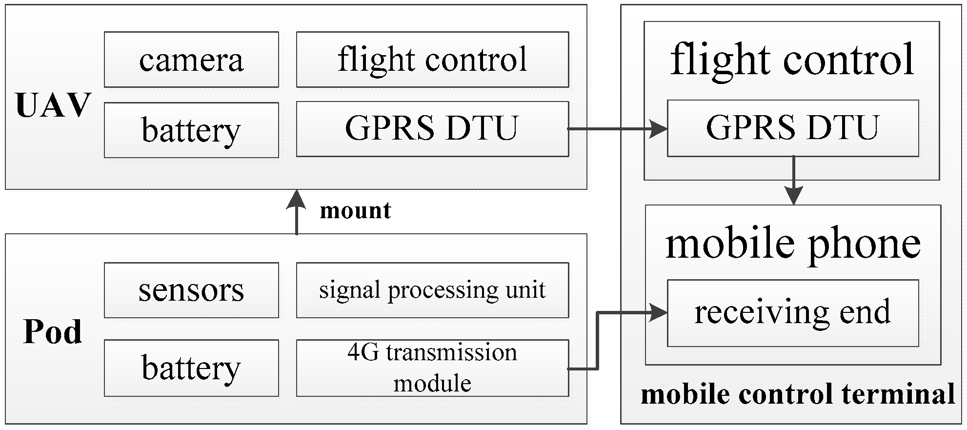
We designed a UAS to collect exhaust gas in our field tests. The UAS includes three main parts: A rotary unmanned aerial vehicle (UAV), a lightweight pod for exhaust monitoring, and a mobile control terminal. A schematic of the system architecture is shown in
Figure 1, and a photograph of our UAS is shown in
Figure 2.
A UAV needs to fly near ship emissions to measure them, and flight safety can be affected by wind speed, wind direction, and other obstacles. Furthermore, operators usually control UAVs at a certain distance from the ship emissions. They need to check video images and exhaust measurement values transmitted by the sensors in real time to better control the collection of exhaust gases by the UAV. The UAV used in the present study was a MATRICE 600 (SZ DJI Technology Co., Ltd., Shenzhen, China) with dimensions of 1668 mm × 1518 mm × 727 mm, a weight of 9.5 kg, and a nonloaded hover time of 32 min. The UAV carries a camera, battery, flight control, and general packet radio service (GPRS) data transfer unit (DTU). When the UAV flies close to a plume, the GPRS DTU transmits the video from the camera back to the mobile control terminal in real time (
Figure 1).
The pod used for exhaust monitoring includes sensors for measuring SO
2 and NO
2, a signal processing unit, and a 4G transmission module, amongst other components (
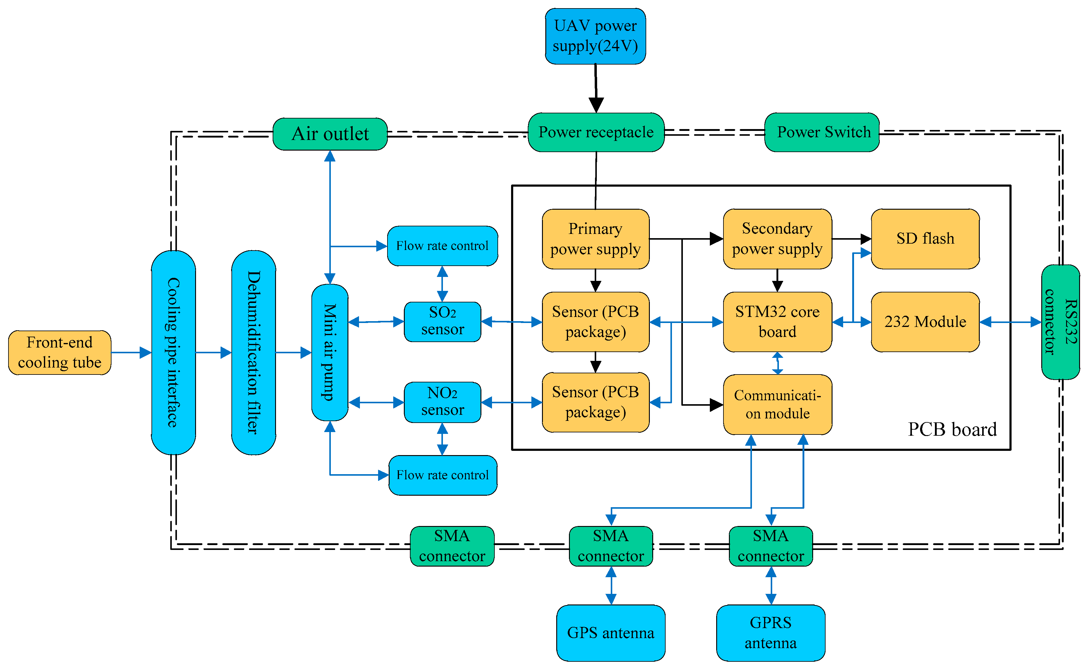
Figure 3). Once gas is detected by the sensors, the measurement is converted into a digital signal by the signal processing unit and then transmitted to the mobile control terminal via the 4G transmission module. The pod is attached to the underside of the UAV with a stand and obtains power from the UAV’s power supply.
When the UAV approaches a plume, the mini air-pump in the UAV extracts gas in the front-end cooling pipe (
Figure 3) of the pod for cooling. Water vapor and particulate matter generated by cooling are then filtered through the dehumidification filter module to improve the accuracy of subsequent gas monitoring and the working life of the equipment. The flow rate control module of the air pump improves the cooling efficiency and reliability of the equipment. According to the actual temperature of tail gas sampling after cooling, the air extraction speed of the micro air pump can be controlled to stabilize the temperature of tail gas after cooling. The sensors detect the processed gas through the sampling module and send gas concentration data to the main control processing module through the communication port.
In the present study, we mainly measured SO2 and NO2 in the plume. The sensors of SO2 and NO2 are based on electrochemical principles and have a measurement range of 0–10 ppm for ships using low-sulfur fuel and 0–100 ppm for high-sulfur fuel. The accuracy is ± 5% (full range), the response time (t90) is <1 s, nonlinearity is no more than ± 1%, and the power dissipation is <1.0 w; t90 is defined as the time taken to reach 90% of the stable response after a step change in the sample concentration. These sensor characteristics were provided by the instrument manufacturer (HH Feuerungstechnik GmbH, Germany). The sensors must be calibrated to ensure that the sensor characteristics are within the instrument’s tolerances. In the calibration process, the zero and full scales are usually calibrated by a standard mixed gas. The time interval for sensor calibration is three months or when the accumulated working time exceeds 180 h. If either of these conditions is met, calibration will be carried out. Sensor measurements are sent to the communication module and a secure digital (SD) memory flash drive. Finally, measurement data is sent out by a GPRS antenna. In addition, a STM32 chip is used as the main control chip, and two levels of power supply conversion provide power for the pod.
Figure 4 shows an example of the interface displayed on the mobile control terminal, which mainly includes the real-time video image taken by the camera on the UAV, an electronic map (including flight path), flight status information, and the real-time gas measurements monitored by the pod. This allows UAV operators to measure ship plumes more safely and conveniently in real time.
3. Experiments, Results, and Discussion
We undertook a field test of our UAS to determine its feasibility, efficiency, and timeliness for obtaining gas measurements from berthing ship plumes. We measured three plumes at Waigaoqiao port in Shanghai, an ECA in China, on March 1 (plumes 1 and 2) and June 1 (plume 3), 2018, and three plumes at Lianyungang port in Jiangsu Province, China, on June 21 (plume 4) and June 22 (plumes 5 and 6), 2018.
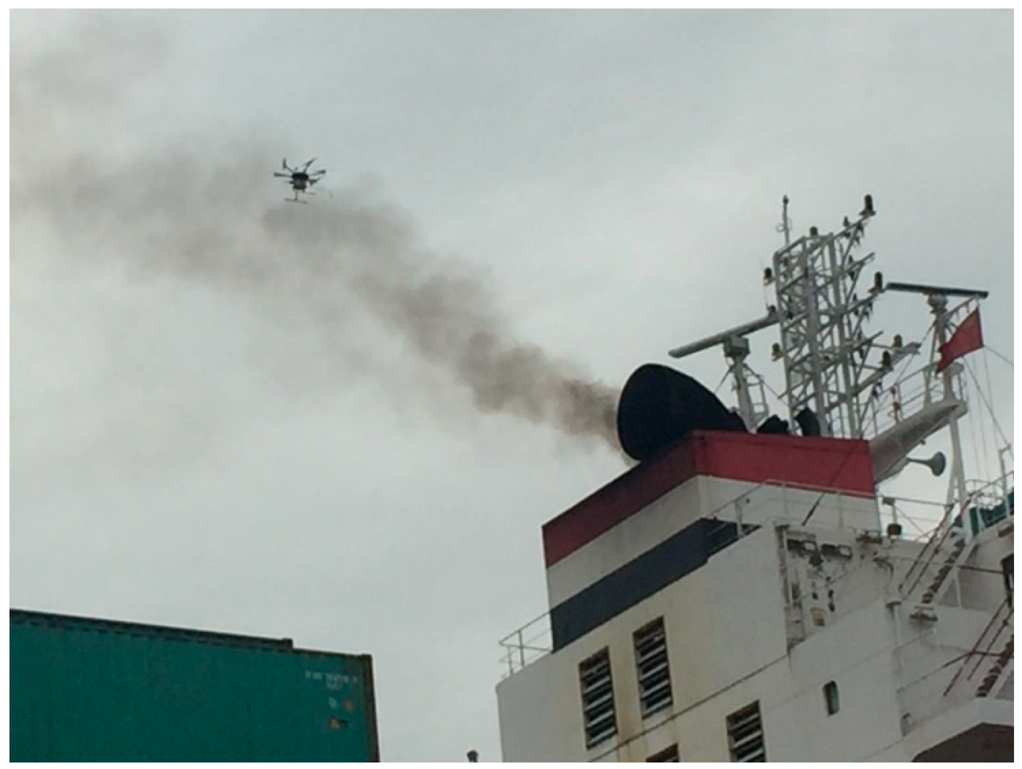
Figure 5 shows a photograph of our UAS during field testing. Our UAV was able to hover around the emission plume in order to collect sufficient plume gas for measurement of SO
2 and NO
2 and thus facilitated the characterization of the sampled plumes. Compared with land-based measurements, a UAV can measure a ship’s plume at close range, meaning that the effects of wind speed and direction are lesser, and better flexibility and stability is ensured. Furthermore, this approach incurs lesser costs and is safer than airborne-based measurements.
In the experiment, one person operated the UAV to monitor the plume, and two maritime law enforcement officers boarded the berthing ship to collect fuel samples for chemical analysis. The measured SO
2 and NO
2 concentrations in the six plumes are shown in
Figure 6. The sampling interval was 10 s in the six experiments, but the effective collection time (i.e., when the concentrations of SO
2 and NO
2 were actually measured) of each plume was different. The effective collection times were affected by wind speed, wind direction, position of the UAV, and smoke, amongst other conditions.
Plumes 1–3 came from ships that used low-sulfur fuel (FSC ≤0.5% (m/m)), whereas plumes 4–6 came from ships that used high-sulfur fuel (FSC >0.5% (m/m)).
Figure 6 shows the fluctuations in the measured concentrations of SO
2 and NO
2 in the plumes, which mainly relate to wind speed, wind direction, and different positions of the UAV in the plume. However, the trends for SO
2 and NO
2 measured in the six sets of measurements were similar. In addition, it can be seen from
Figure 6d, e that the observation time was relatively long, and the SO
2/NO
2 trend was clearer. Our findings therefore suggest that the SO
2/NO
2 ratio can be used to distinguish the FSC of ships.
To verify the accuracy of our measurements, we determined the average and root-mean-square error (RMSE) of the SO
2/NO
2 ratio in each of the six plumes and in the FSC obtained from fuel samples, as shown in
Table 1. We compared the two sets of results as a means of analyzing the relationship between FSC and the SO
2/NO
2 ratio.
Table 1 shows that the average SO
2/NO
2 ratio was <1 when the FSC did not exceed 0.10% (m/m) (plumes 1 and 2). In plume 3, the average SO
2/NO
2 ratio was 1.87, and the FSC was 0.41% (m/m). The SO
2/NO
2 ratios in high-sulfur fuel (i.e., plumes 4–6) were significantly higher than those in low-sulfur fuel (i.e., plumes 1–3). Furthermore, the highest RMSEs were associated with the highest FSC (i.e., plumes 5 and 6). However, we note that the relationship between the SO
2/NO
2 ratios and the FSC was not strictly proportional. The main reasons for this result are as follows: (1) ships typically emit 40–90 g NOx per kg of fuel [
7], and the emission depends on several factors, including ship age, type, size, and load as well as possible emission abatement systems. (2) The NO/NO
2 ratio in the exhaust gas is also associated with uncertainties. (3) 1–19% of the sulfur in the fuel is emitted in other forms, possibly SO
3 or SO
4 [
4,
5]. (4) Unstable concentrations of SO
2 and/or NO
2 may exist in the plume.
Nevertheless, it can be seen that the UAS presented in this study can provide an active, close-range, low-cost, and accurate measurement approach for monitoring ship emissions in real time. Our measurement results are consistent with those reported in previous studies [
4,
6,
15], which also found that SO
2/NO
2 ratios can be used, to a certain degree, to ascertain the sulfur content of ship fuel.
4. Conclusions
Since the IMO regulations concerning the sulfur content of ship emissions came into force in 2005, an increasing amount of research has been undertaken regarding this topic. Hence, policies relevant to ECAs have effectively powered this research, especially studies addressing the effect of implemented policies on air quality through monitoring and characterizing ship emissions. However, how to perform efficient, accurate, and timely measurements of pollutant gases in a ship’s plume remains a key problem in the field of ship emissions.
In the present study, we designed a UAS suitable for collecting ship exhaust gas that includes three main parts: A UAV, a lightweight pod for exhaust monitoring, and a mobile control terminal. We conducted field tests with sensors for SO2 and NO2, with results evidencing the success of our UAS for monitoring ship emissions in real time. In comparison to land-based and airborne-based measurements, our UAS provides an effective, accurate, timely, relatively low-cost method that takes into consideration safety issues for operators. Measurements of SO2 and NO2 concentrations allowed us to calculate the SO2/NO2 ratios in six plumes, which were useful for ascertaining the sulfur content of ship fuel.
In the future, we plan to modify the pod to carry more sensors and infrared cameras and use better battery technology, if available. Furthermore, we hope to extend our preliminary experiments for ships at sea as opposed to berthing ships, which requires that we resolve issues relating to accurately finding the plume. These aspects all represent possibilities for further investigation.


